

MINiBOX 20
2-Output Multifunction Actuator
ZIO-MN20
USER MANUAL
Application programme version: [1.3]
User manual edition: [1.3]_a
www.zennio.com

MINiBOX 20
http://www.zennio.com Technical Support: http://support.zennio.com
2
CONTENTS
Contents ........................................................................................................................................ 2
Document Updates ....................................................................................................................... 3
1. Introduction .......................................................................................................................... 4
1.1 MINiBOX 20 ...................................................................................................................... 4
1.2 Installation ........................................................................................................................ 5
1.3 Start-Up and Power Loss .................................................................................................. 6
2. Configuration......................................................................................................................... 7
2.1 General ............................................................................................................................. 7
2.2 Outputs............................................................................................................................. 9
2.2.1 Manual Control ........................................................................................................ 9
2.3 Logic Functions ............................................................................................................... 13
2.4 Scene Temporisation ...................................................................................................... 14
ANNEX I. Communication Objects............................................................................................... 16

MINiBOX 20
http://www.zennio.com Technical Support: http://support.zennio.com
3
DOCUMENT UPDATES
Version
Changes
Page(s)
[1.3]_a
Changes in the application program:
Optimisation of the individual outputs, logic functions,
shutter channel y heartbeat modules.
-
Minor text changes.
-

MINiBOX 20
http://www.zennio.com Technical Support: http://support.zennio.com
4
1. INTRODUCTION
1.1 MINiBOX 20
MINiBOX 20 from Zennio is a versatile and small-size KNX actuator featuring a wide
variety of functions and four relay outputs for a variety of applications, such as
controlling shutter drives.
The most outstanding features are:
2 relay outputs, configurable as:
1 shutter channels (with or without slats), or
Up to 2 individual ON/OFF outputs,
10 customisable, multi-operation logic functions.
Scene-triggered action control, with an optional delay in the execution.
Manual operation / supervision of the 2 relay outputs through the on-board
pushbuttons and LEDs.
Heartbeat or periodical “still-alive” notification.
MINiBOX 20
http://www.zennio.com Technical Support: http://support.zennio.com
5
1.2 INSTALLATION
MINiBOX 20 connects to the KNX bus through the on-board KNX connector.
Once the device is provided with power from the KNX bus, both the individual address
and the associated application programme may be downloaded.
This device does not need any additional external power since it is entirely powered
through the KNX bus.
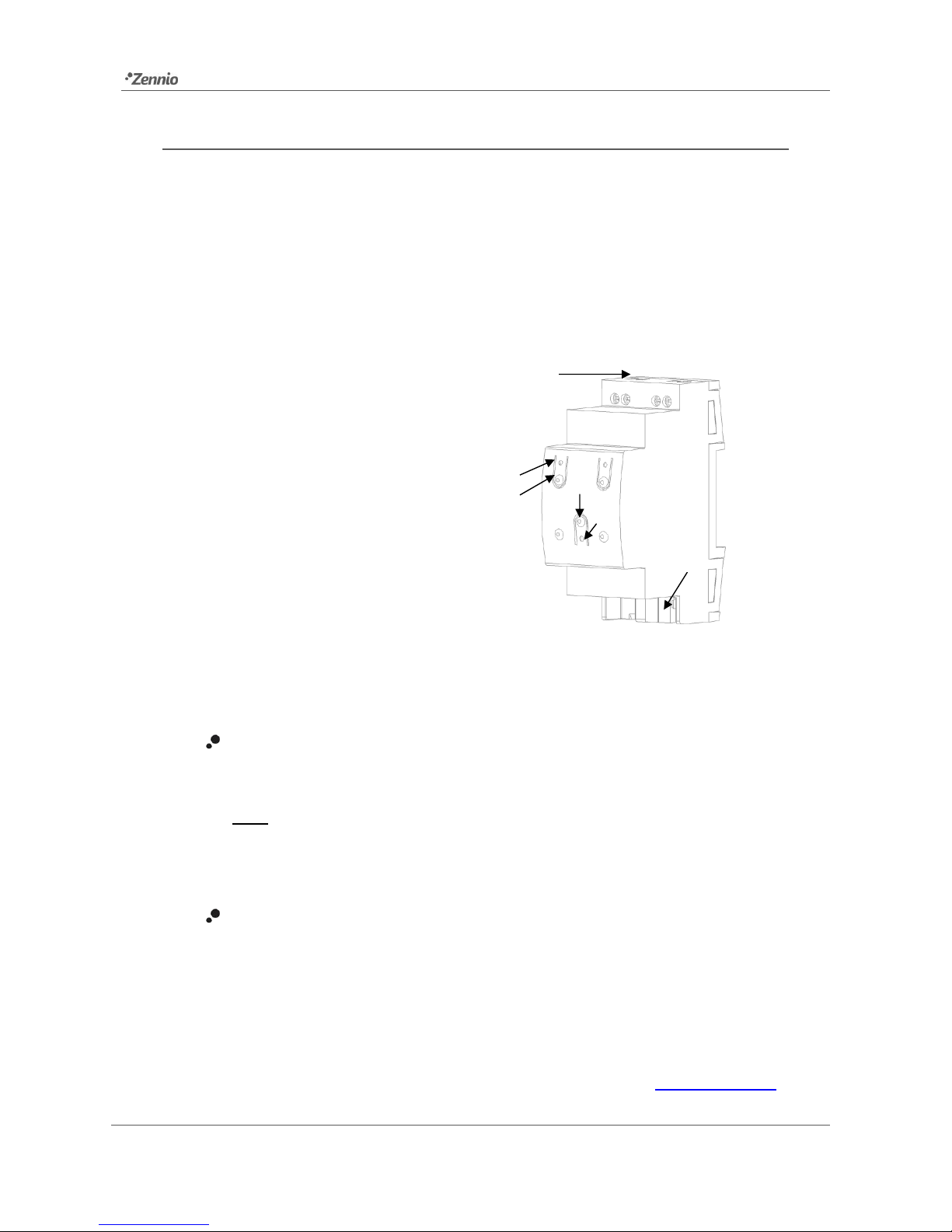
Figure 1. MINiBOX 20. Elements.
The main elements of the device are described next.
Prog./Test Pushbutton (5): a short press on this button sets the device into
the programming mode, making the associated LED (5) light in red.
Note: if this button is held while plugging the device into the KNX bus, the
device will enter into safe mode. In such case, the LED will blink in red every
0.5 seconds.
Outputs (6): output ports for the insertion of the stripped cables of the
systems being controlled by the actuator (see section 2.2). Please secure the
connection by means of the on-board screws.
To get detailed information about the technical features of this device, as well as on the
installation and security procedures, please refer to the corresponding Datasheet,
bundled with the original package of the device and also available at www.zennio.com.
1. Output Status LED Indicator.
2. Manual Control Pushbutton.
3. KNX Connector.
4. Prog./Test LED.
5. Prog./Test Pushbutton.
6. Relay Outputs.
1
2
3
4
5
6

MINiBOX 20
http://www.zennio.com Technical Support: http://support.zennio.com
6
1.3 START-UP AND POWER LOSS
During the start-up of the device, the Prog./Test LED will blink in blue colour for a few
seconds before the device is ready. External orders will not be executed during this
time, but afterwards.
Depending on the configuration, some specific actions will also be performed during
the start-up. For example, the integrator can set whether the output channels should
switch to a particular state and whether the device should send certain objects to the
bus after the power recovery. Please refer to the next sections of this document for
further details.
On the other hand, when a bus power failure takes place, the device will interrupt any
pending actions, and will save its state so it can be recovered once the power supply is
restored. For safety reasons, all shutter channels will be stopped (i.e., the relays will
open) if a power loss takes place, while the individual outputs will switch to the specific
state configured in ETS (if any).
 Loading...