

KES Plus
KNX Energy Meter
ZIO-KESP
USER MANUAL
Application Program Version: [1.2]
User Manual Version: [1.2]_a
www.zennio.com

KES Plus
http://www.zennio.com Technical Support: http://support.zennio.com
2
CONTENTS
Contents ........................................................................................................................................ 2
Document Updates ....................................................................................................................... 3
1 Introduction ............................................................................................................................. 4
1.1 KES Plus ............................................................................................................................ 4
1.2 Installation ........................................................................................................................ 5
1.2.1 Current Transformer ................................................................................................. 6
1.2.2 KES Plus use cases in different types of installations ............................................... 7
1.3 Measured Quantities ...................................................................................................... 10
1.4 Consumption data Initialization after a download ......................................................... 13
1.5 Setting the time of day ................................................................................................... 15
1.6 Visual Notification .......................................................................................................... 16
2 Configuration ......................................................................................................................... 17
2.1 General ........................................................................................................................... 17
2.2 Phases ............................................................................................................................. 21
2.2.1 General configuration ............................................................................................. 21
2.2.2 Single phase system ................................................................................................ 22
2.2.3 Three-Phase System ............................................................................................... 30
2.3 Tariffs .............................................................................................................................. 33
2.4 Notifications ................................................................................................................... 35
2.4.1 Notification n .......................................................................................................... 36
2.5 Alarms ............................................................................................................................. 37
2.5.1 Alarm n ................................................................................................................... 38
2.6 Logic Functions ............................................................................................................... 40
ANNEX I: Comunication Objects .................................................................................................. 41

KES Plus
http://www.zennio.com Technical Support: http://support.zennio.com
3
DOCUMENT UPDATES
Version
Changes
Page(s)
[1.2]_a
Changes in the application program:
• Global consumed and generated power objects are
included.
• V and A are added to the voltage and current unit
selector.
• Sending of voltage and current magnitudes.
• Alarms for generated power.
-
V and A are added to the voltage and current unit selector.
21
Sending voltage and current magnitudes.
27, 31
Alarms for generated power.
38

KES Plus
http://www.zennio.com Technical Support: http://support.zennio.com
4
1 INTRODUCTION
1.1 KES PLUS
The KES Plus (KNX Energy saver) from Zennio is an energy saver of electrical energy
for single-phase or three-phase systems.
It can measure and notify in KNX system, not only the consumed or produced energy,
but also the associated cost according to 6 different tariffs, CO2 emissions, instant
active and reactive power, power factor and other information related with the use of
electric energy in the installation.
Alarms and notifications can be configured as warnings when power exceeds the limits
established, for example, to disconnect low priority systems to reduce consumption.
The most outstanding features of KES Plus are:
Support for frequencies of 50 and 60 Hz.
Support for single-phase and three-phase systems.
3 independent input channels to monitor up to three independent single-
phase lines or one three-phase line. Power and energy, cost and CO2
emissions measurement in up to 3 registers (one total and two partial).
Up to 6 tariff counters for the estimation of the cost of energy consumption.
4 Alarms for power excess and low power.
Up to 15 notifications of different situations: overvoltage, low voltage, excess
of consumption, energy generation, economic cost, CO2 emissions.
Synchronisation with an external KNX clock.
10 customisable, multi-operation logic functions.
Heartbeat or periodic “still-alive” notification.

KES Plus
http://www.zennio.com Technical Support: http://support.zennio.com
5
1.2 INSTALLATION
KES Plus connects to the KNX bus via the connecting terminals.
The current transformers Zennio (ZN1AC-CST60 and ZN1AC-CST120) are connected
to KES Plus input channels.
KES Plus can be used in single-phase and three-phase installations with and without
accessible neutral wire. Please refer to section 1.2.2 to get detailed information about
the different use cases and connection schemes for each type of installation.
Once KES Plus is provided with power from the KNX bus, both the individual address
and the associated application program can be downloaded.
Figure 1 shows the element scheme of KES Plus.
Figure 1. KES Plus. Element scheme.
The functionality of the main elements is described below:
Phase/line (voltage) (1): inputs for the Phase/line connection.
Neutral (voltage) (2): inputs for the Neutral connection.
Programming Button (3): a short press on this button sets the device into the
programming mode, making the associated LED (4) light in red.
Note: If this button is held while plugging the device into the KNX bus, KES
will enter the Safe Mode. The LED will then blink in red every 0.5 seconds.
3 8 5
7
1
2
6
9
4
1. Phase/line (voltage)
2. Neutral (voltage)
3. Programming button
4. Programming LED
5. Phase/line status LED
6. Current transformer connection
7. KNX connector
8. Three-phase status LED
9. Current Transformer
KES Plus
http://www.zennio.com Technical Support: http://support.zennio.com
6
Current Transformer connection (6): inputs for the current transformers
connection. A different transformer will be required per electrical line being
monitored. The two wires of each transformer will be inserted into the two
connection points of the particular input channel to be used. For instance, if
three electrical lines are going to be monitored, one transformer will need to
be connected to the slots CT1 +/- (referred to as “Phase 1” in the SinglePhase application program), another one to the slots CT12 +/- (“Phase 2”),
and a third one to the slots CT3 +/- (“Phase 3”). In the case of the ThreePhase version, each transformer will be destined to monitor one of the three
phase lines in the electrical system.
To get detailed information about the technical features of the device, as well as on the
installation and security procedures, please refer to the corresponding Datasheet,
bundled with the original package of the device and also available at www.zennio.com.
1.2.1 CURRENT TRANSFORMER
The set-up process of the ZN1AC-CST60 and ZN1AC-CST120 transformers is
described below.
Open the top clamp of the transformer.
Put the wire of the phase to be measured inside it respecting the orientation.
Important: only one phase line should be inserted into the transformer, not
the entire power cable with the neutral and other phases.
Close back the top clamp of the transformer.
Connect the two wires of the transformer into the two connection slots of the
KES Plus terminal block (6).
Please remember that KES Plus only performs measurements of the power consumed
by alternating current (AC) lines.
Note: it is very important to keep in mind that neither ordinary power supplies (230 V)
nor other external supplies should be connected to the KNX bus, nor directly to the
input terminal probes of KES Plus.

KES Plus
http://www.zennio.com Technical Support: http://support.zennio.com
7
1.2.2 KES PLUS USE CASES IN DIFFERENT TYPES OF INSTALLATIONS
The following figures show the connection diagram of KES Plus in different types of
installations:
Case 1: Three-phase installation with accessible neutral wire and three-phase load
Figure 2 Three-phase with accessible neutral wire and three-phase load.
Case 2: Three-phase installation with accessible neutral wire and single-phase loads
Figure 3 Three-phase with accessible neutral wire and single-phase loads.
Load T
-N
Load S
-N
Load R
-N
To obtain measurements per
phase: parameter setting as
single-phase system (see section
2.2.2).
Three-
phase load
Parameter setting as three-phase system
(see section 0).

KES Plus
http://www.zennio.com Technical Support: http://support.zennio.com
8
Case 3: Single-phase installation with accessible neutral wire or two-phase with
U
Línea
≤230V
Figure 4 Single-phase system with accessible neutral wire or two-phase system.
Case 4: Three-phase installation without accessible neutral wire and three-phase
load
Figure 5 Three-phase system without accessible neutral wire and three-phase load.
Three-
phase
load
Parameter setting as three-phase
system (see section 0).
Circuit 3 Circuit 2 Circuit 1
Parameter setting as single-phase
system (see section 2.2.2).
For two-phase systems:
Phase voltage ≤ 230V
KES Plus
http://www.zennio.com Technical Support: http://support.zennio.com
9
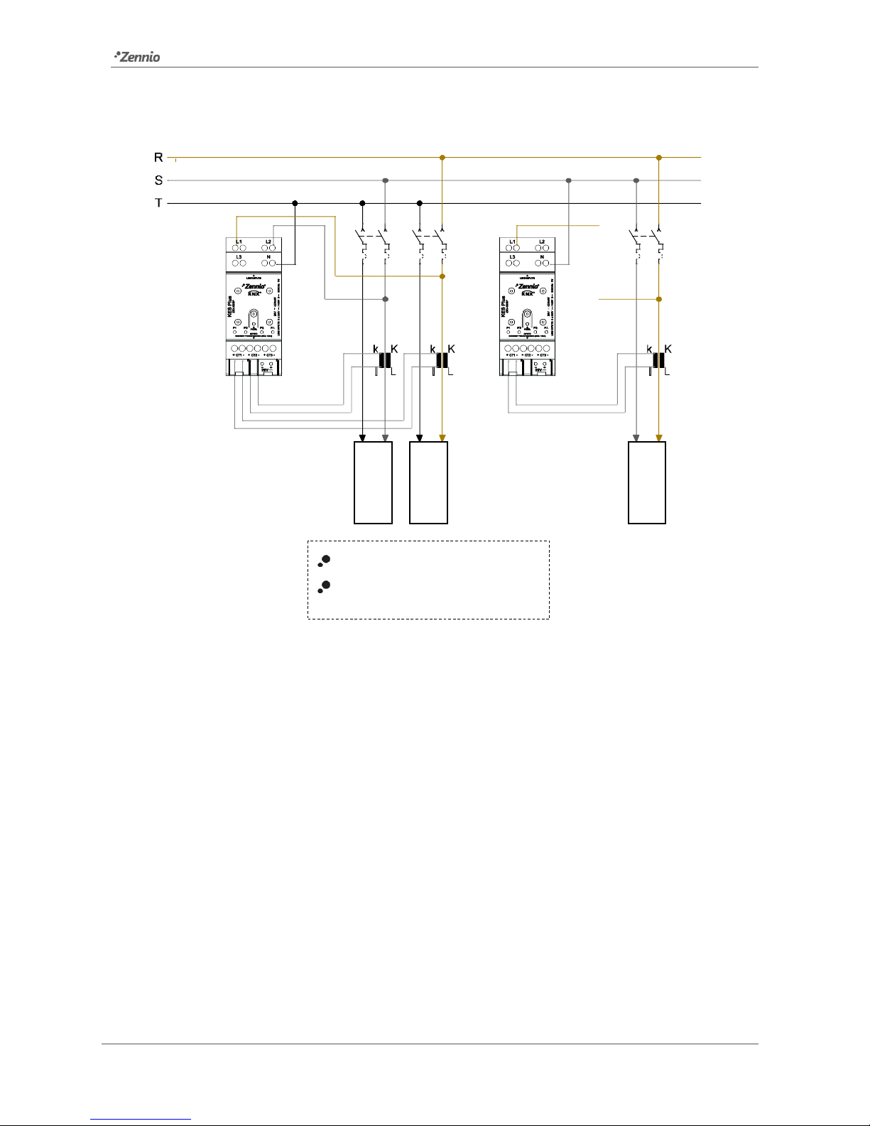
Case 5: Three-phase installation without accessible neutral wire and three singlephase loads
Figure 6 Three-phase system without accessible neutral wire and single-phase loads.
In this case, since two KES Plus are used, the power measurements per phase can be
added together using a logic function (section 2.6) to obtain total (three-phase) power
measurements, provided they are set in kW.
Load S
-T
Load R
-T
Load R
-S
Phase voltage ≤ 230V
Parameter setting as single-phase
system (see section 2.2.2).

KES Plus
http://www.zennio.com Technical Support: http://support.zennio.com
10
1.3 MEASURED QUANTITIES
Next, the quantities measured by the KES Plus that can be sent to the bus for
monitoring and energy management are described.
T magnitude available for three-phase systems.
S magnitude available for single-phase systems.
Magnitudes of each conductor or phase:
Phase Voltage (T/S): rms value expressed in millivolts [mV] or volts [V].
Phase Current (T/S): rms value expressed in milliamps [mA] or amps [A].
Active Power (S): effective power capable of transforming electrical energy
into work. Measured in watts [W] or kilowatts [kW], as selected by parameter,
with 2W-resolution. The sign of this magnitude indicates whether the power is
being consumed or generated:
➢ Active Power > 0 Active power consumed (the receptor is a load,
absorbing power from the electricity grid).
➢ Active Power < 0 Active power generated (the receptor is a generator,
injecting power to the electricity grid).
Power Factor (S): relation between active and apparent power
(dimensionless).
Active Energy (S): time integration of the active power. It is disaggregated in
two objects, active energy consumed and active energy generated (always
positive values). Measured in watts per hour [W·h] or kilowatts per hour
[kW·h], as selected by parameter.
Global magnitudes:
Frequency (T/S): weighted average of the frequencies of each phase
connected. Measured in hertz [Hz].
Consumed Active Power (S): Sum of the consumed active power of each
phase. Resolution: 8W

KES Plus
http://www.zennio.com Technical Support: http://support.zennio.com
11
Generated Active Power (S): Sum of generated active power of each phase.
Resolution: 8W
Active Power (T/S): arithmetic sum of the active power of each phase.
Resolution: 8W.
Reactive Power (T/S): power developed in capacitive and inductive circuits.
Measured in volt-ampere reactive [VAr] or kilovolt-ampere reactive [kVAr], as
selected by parameter. The reactive power would have two possible meanings
depending on its sign:
➢ Inductive Reactive Power would have a positive sign in consumption and
a negative sign in generation, with load mainly of inductive type.
➢ Capacitive Reactive Power would have a negative sign in consumption
and a positive sign in generation, with load mainly of inductive type.
Power Factor (T/S): relation between active and apparent power.
Active Energy (T/S): time integration of the global active power. It is broken-
down in two objects, active energy consumed and active energy generated
(always positive values). Measured in watts·hour [W·h] or kilowatts·hour
[kW·h], as selected by parameter.
Reactive Energy (T/S): time integration of the global reactive power. It is
broken-down in two objects, inductive reactive energy and capacitive active
energy (always positive values). Measured in volt-ampere reactive hour
[VAr·h] or kilovolt-ampere reactive hour [kVAr·h], as selected by parameter.
Voltage and Current Unbalance (T): measures, as a percentage, the
difference between voltages and currents of each one of the phases. The
calculation is done in accordance with IEC 61000-2-1, IEC 61000-4-27, ANSI
C84.1 standards for phase voltages.
𝐷𝑖=
𝐼
𝑚𝑎𝑥
− 𝐼
𝑚𝑒𝑑
𝐼
𝑚𝑒𝑑
100%; 𝐷𝑣=
𝑉
𝑚𝑎𝑥
− 𝑉
𝑚𝑒𝑑
𝑉
𝑚𝑒𝑑
100%
The following table resumes the mentioned magnitudes.

KES Plus
http://www.zennio.com Technical Support: http://support.zennio.com
12
Phase /
Global
Magnitude
Units
Single
Phase
ThreePhase
Per Phase
Voltage
mV / V
Current
mA / A
Active Power
W / kW
Active Consumed Energy
W·h / kW·h
Active Generated Energy
W·h / kW·h
Power Factor
-
Global
Frequency
Hz
Consumed Active Power
W / kW
Generated Active Power
W / kW
Active Power
W / kW
Reactive Power
VAr / kVAr
Active Energy Consumed
W·h / kW·h
Active Energy Generated
W·h / kW·h
Inductive Reactive Energy
VAr·h / kVAr·h
Capacitive Reactive Energy
VAr·h / kVAr·h
Power Factor
-
Voltage Unbalance
%
Current Unbalance
%
Table 1. Quantities measured in Single and Three-Phase systems

KES Plus
http://www.zennio.com Technical Support: http://support.zennio.com
13
1.4 CONSUMPTION DATA INITIALIZATION AFTER A
DOWNLOAD
It is important to keep in mind that, when reprogramming the device from ETS (either
partial or complete downloads), the consumption variables and therefore any data
accumulated so far are cleared on both partial and total registers.
If it is required to maintain the present consumption values, before carrying out the
download, the option to maintain the current values must be activated in ETS in the
desired registers, or an initial value must be parameterised (see sections 2.2.2.2 and
2.2.3.1).
There are also certain objects with the flag W enabled, so they can be initialized
directly writing the desired value in the communication object.
Notes:
In single-phase configuration, only the energy registers broken down by each
phase can be initialized by parameter, not the global registers.
Reactive energy registers can only be initialized by writing in the
communication object. It is recommended to initialize them after the first startup as they may have invalid values.
Table 2 shows the available options to set the initial value in each energy register. The
options are:
By parameter.
By object: writing the desired value in the corresponding communication
object.
Reset register: partial registers can be reset (set to zero) through the reset
communication object.

KES Plus
http://www.zennio.com Technical Support: http://support.zennio.com
14
Phase / Global
Magnitude
Initialization
Single Phase
Three-Phase
Per
Phase
Total
Register
Active Energy
Consumed
- By parameter
- By object
Active Energy
Generated
- By parameter
- By object
Partial
Register
Active Energy
Consumed
- By parameter
- Reset register
Active Energy
Generated
- By parameter
- Reset register
Global
Total
Register
Active Energy
Consumed
-
- By parameter
- By object
Active Energy
Generated
-
- By parameter
- By object
Capacitive
Reactive Energy
- By object
- By object
Inductive
Reactive Energy
- By object
- By object
Partial
Register
Active Energy
Consumed
- Reset register
- By parameter
- Reset register
Active Energy
Generated
- Reset register
- By parameter
- Reset register
Capacitive
Reactive Energy
- Reset register
- Reset register
Inductive
Reactive Energy
- Reset register
- Reset register
Table 2 Consumption data initialization.

KES Plus
http://www.zennio.com Technical Support: http://support.zennio.com
15
1.5 SETTING THE TIME OF DAY
For certain functionalities, such as periodic registers or the starting date of each
register, it is necessary to set the time of day of KES Plus through a master clock in the
installation.
During the start-up, KES Plus will request the time of day to the KNX bus through the
objects “Date” and “Time of day”. Up to four read requests will be sent (after a
customisable initial delay).
Notes:
The time count is performed internally by KES Plus. However, it must be
notified (through external events) of any time adjustments in order to ensure
the synchronisation of the periodic timing of the registers.
It is advisable to resynchronise the internal clock of KES Plus periodically to
prevent precision loss after prolonged operation. Therefore, KES Plus sends a
time request to the KNX bus every 15 minutes.
 Loading...