

IRSC Zone
Zone Climate Controller
ZN1CL-IRSC
USER MANUAL
Application program version: [1.7]
User manual edition: [1.7]_a
www.zennio.com

IRSC Zone
http://www.zennio.com Technical Support: http://zennioenglish.zendesk.com
2
Contents
Document updates ................................................................................................................... 3
1 Introduction ...................................................................................................................... 4
1.1 The IRSC Controller .................................................................................................... 4
1.2 Installation ................................................................................................................ 4
1.3 The IRSC Zone application program ........................................................................... 6
2 Configuration .................................................................................................................... 8
2.1 General concepts ....................................................................................................... 8
3 ETS Parametrization .......................................................................................................... 9
3.1 Default configuration ................................................................................................. 9
3.2 General.................................................................................................................... 11
3.3 Mode ....................................................................................................................... 14
3.4 Fan .......................................................................................................................... 16
3.5 Temperature ........................................................................................................... 17
3.6 Thermostat .............................................................................................................. 20
3.7 Reset ....................................................................................................................... 21
Annex I. Installation Scheme ................................................................................................... 23
Annex II. Grille control ............................................................................................................ 24
Switching zones on / off ...................................................................................................... 24
Thermostatic control for cooling ......................................................................................... 25
Thermostatic control for heating ......................................................................................... 26
Annex III. Practical example .................................................................................................... 27
Annex IV. Communication objects ........................................................................................... 29

IRSC Zone
http://www.zennio.com Technical Support: http://zennioenglish.zendesk.com
3
DOCUMENT UPDATES
Version Modifications Page(s)
[1.7]_a
Changes in the application program:
- New param eter added (“Zone updat e after reset”) to
all ow sending read r equests for the states, modes and
zone setpoints after bus failures.
- Revisi on of texts and parameter names.
- Function added to let the device store the current mode
on bus failures even if the m achine was off.
- Inversion of the ord er of certain read requests sent after
reset, in ord er to avoid unexpected behavi ours of the
device (such as when both the normal
mode and the
extended mode read r equests receive a r esponse).
- Implementation of the temperature restriction even when
the machine is off, not only when it gets switched on.
- Reset of the vari ables of the PI control algorithm when
power failures occur.
-
Revisi on of the d escription about the “Open byp ass if…”
parameter.
12
New param eter added: “Zone update after reset”. 13
Ext ended description about the tem perature r estriction
function.
18-19
Revisi on of the practical exam ple in Annex III. 27
Revision of texts and styles. -
[1.6]_a
Changes in the application program:
Option added
to send read requests to the bus of certain
objects in order to recover the st ate of the device
after a
download or a device res et from ETS.
-
IRSC Zone
http://www.zennio.com Technical Support: http://zennioenglish.zendesk.com
4
1 INTRODUCTION
1.1 THE IRSC CONTROLLER
The IRSC controller from Zennio is aim ed at controlling air conditioning systems
featuring infrared receivers (such as splits, ducted units with an integrated infrared
interface, etc) through the emulation of their IR r em ote c ontrol syst ems. In fact, IRSC
com bines the following functions into the same device:
Control of the main functionalities of A/C units (On/Off, temperature, mode,
fan speed, etc).
Compatibility with most air conditioning manufacturers (pl ease refer to the
correspondence table, avail able at: http://www.zennio.com.
Device management through infrared codes:
Split units (application program IRSC PLUS)
A/V systems (application program IRSC OPEN)
Ducted cooling/heating machines, with multiple zones to be acc limated
(application program IRSC Zone)
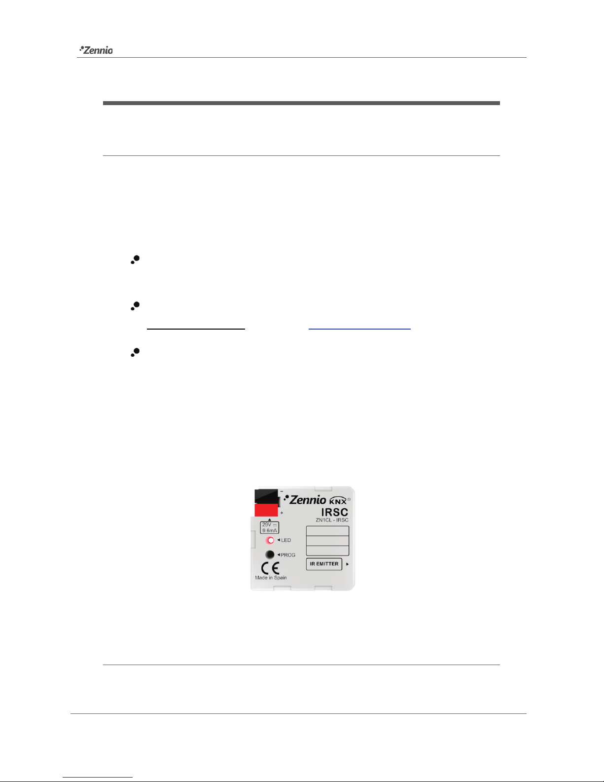
Figure 1. IRSC Controller
1.2 INSTALLATION
The IRSC controller is connected to the KNX bus via the bus connecting terminals.
IRSC Zone
http://www.zennio.com Technical Support: http://zennioenglish.zendesk.com
5
Once the controll er is provided w ith power from the KNX bus, both the physic al
address and the associated application program may be downloaded.
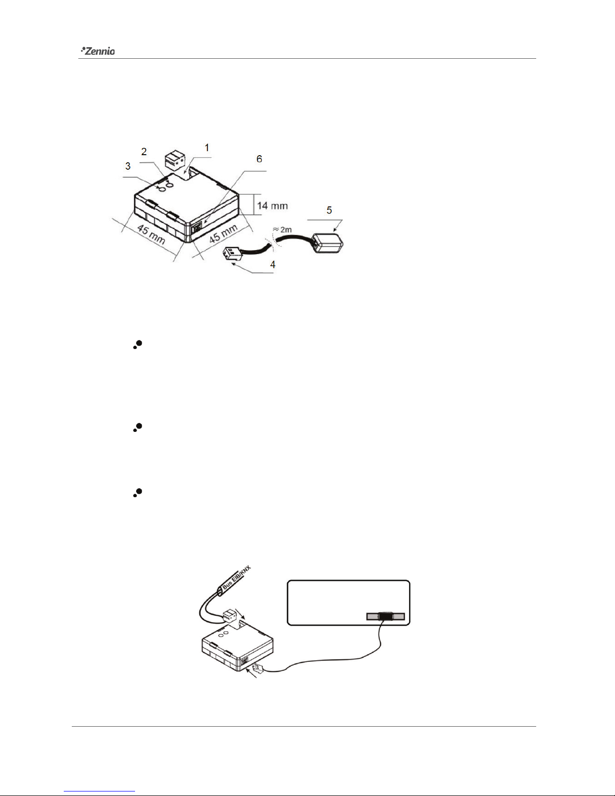
In Figure 2, the connection scheme of IRSC is shown.
Figure 2. IRSC Element diagram
The functionality of the m ain elem ents is described next.
Programming button (3): a short press on this button sets the device into
the programming mode, making the associated LED (2) light in red. If this
button is held while plugging the device into the KNX bus, IRSC goes into
secure mode.
IR emitter (5): infrared fl ashing diode to send commands to the air
conditioning system. It must be placed in front of th e air conditioning IR
receiver (see Figure 3).
Socket for the aerial connector (6): slot for the insertion of the aerial
connector, through which the IR commands are outputted from IRSC.
Figure 3 shows how to locate the IR emitter (5) in front of the clim ate system.
Figure 3. IRSC - A/C unit interface
1.- KNX Connector.
2.- Programming LED.
3.- Programming button.
4.- Aerial connector.
5.- IR emitter.
6.- Socket for the aerial connector.
IR receiver

IRSC Zone
http://www.zennio.com Technical Support: http://zennioenglish.zendesk.com
6
Once IRSC is connected and properl y parameteris ed, it will be possible t o contr ol the
A/C unit from within the installation (for in stance, from the InZennio Z38i or InZennio
Z41 touch panels), thus achieving an easier and more intuitive control.
Note: only one air conditioning unit may be controlled by each IRSC.
To obtain detail ed information about the t echnical features of IRSC, as well as on
security and inst allation proc edures, pl ease refer to the device Datash eet, provided
with the original p ackaging of the device and also available at http://www.zennio.com.
1.3 THE IRSC ZONE APPLICATION PROGRAM
The IRSC Zone application program has been developed for controlling air
cooling/heating ducted machines, thus allowing acclimatizing, within the sam e KNX
installation, up to 8 room s (or zones) where the air output is regulat ed by gates or
motorised grilles. Grilles are th e fin al el ements of the air ducts in charge of
distributing the air from the central unit to every zone, and permit outputting the
conditioned air to the different zones.
IRSC Zone is ther efore in charge of two complementary functions:
Sending the necessary orders (ON/OFF, tem peratur e, fan, etc) to the central
a/c machine through infrared commands.
Sending the necessary orders to the external KNX actuator that controls the
air grilles.
The independent control of th ese grilles m akes it pos sible, in short, that a sole machine
with a unique setpoint temperature serves each of the zones as convenient, no matter
if the setpoint temperatures of the zones are different.
The central machine is controlled by taking into account the number of the zones to be
acclimatised, as w ell as their own setpoints:
The IRSC Zone application program calculates the setpoint tem peratur e that
the central machine needs to be sent depending on what the desired
tem peratures for the differ ent zon es are.

IRSC Zone
http://www.zennio.com Technical Support: http://zennioenglish.zendesk.com
7
It is optionally possible to make this calculation also depend on an additional
feedback tem peratur e, provid ed by a KNX sensor locat ed next to the air flow
returning to the machine, thus making it possible to correct undesired switch-
offs or adjustments made by the machine itself when it detects that the
ambient temperature of its actual location (which may be subject to punctual
heat or cold sources) is similar to the setpoint, although the ambient
tem peratures of the zones ar e not.
Moreover, this calculation will also consid er any “addition t emperature” other
than zero that m ay have been par am eterised (see Section 3.5).
Apart from sending temperature setpoints and other orders to th e air machine, IRSC is,
as already stated, responsible for controlling the air grilles of the zones, which implies
selecting and applying an algorithm, which, depending on the setpoint and reference
tem peratures of every zone, will continuously determine whether the grille of each zone
must stay open or not.
All the concepts mentioned so far ar e explain ed in detail in section 3. For further details
and for a complete example, please refer to the Annexes of this manual.

IRSC Zone
http://www.zennio.com Technical Support: http://zennioenglish.zendesk.com
8
2 CONFIGURATION
2.1 GENERAL CONCEPTS
The IRSC Zone application program permits controlling air conditioning systems from
different manufacturers as if they were being controll ed through the infrared rem ote
control of the machine.
A correspondence tabl e is avail able at the Zennio homepage (http://www.zennio.com)
with the codes (from 0 to 255) corresponding to the different remote controls that can
be emulated. This num ber is the first parameter to be set in ETS, so that the orders
sent by IRSC become particularised for the actual A/C unit to be controlled.
The IRSC Zone application also allows selecting the number of the zon es of the KNX
installation that will be controlled by the same central A/C machine, which can be 1 – 8.
Moreover, the following functionalities of the A/C system can be controlled by IRSC:
Switching ON/OFF each of the enabl ed zones.
Setpoint temperature of each enabled zone.
Working mode: the desired working mode (Automatic, Heat, Cool, Fan, Dry)
may be chosen through independent binary objects (one per mode) or
through a sole object (only one obj ect for the mode sel ection). Moreover,
apart from these conventional controls, it is possible to enable a simplified
control, w hich only permits commuting from Heat to Cold and vice versa.
Fan speed: step-controlled or through a precise control.
Thermostat: it is possible to enable and configure this functionality for Heat
mode, Cool mode or both.
For further details and examples please refer to the Annexes of this manual.

IRSC Zone
http://www.zennio.com Technical Support: http://zennioenglish.zendesk.com
9
3 ETS PARAMETRIZATION
To begin with the param eterization process of the IRSC controller it is n ecessary, once
the dat a base of the product (IRSC Zone application program) has been imported to
ETS, to add the device to the project where desir ed. After that, one right-click on the
device will permit selecting "Edit param eters", in order to start the configuration.
In the following sections a detail ed explanati on can be found ab out the different
functionalities of IRSC Zone available in ETS.
3.1 DEFAULT CONFIGURATION
This section shows the d efault configuration the device parameterization st arts from for
the first time.
Figure 4. IRSC Zone Default topology
The following communication obj ects appear: "A/C Unit - ON/OFF status", "A/C Unit -
Setpoint status" and "A/C Unit - fan status", all of which will report basic information
about the states of the A/C unit (ON/OFF, setpoint and fan speed).
Seven more objects, of different lengths, are sh own, referred to different functionalities
that may be controlled for Z on e 1 (Z on e 1 is the only zone enabled by default). These
are (“X” means 1 here):
Zone X – ON/OFF: permits turning ON or OFF each of the enabled zones
independently. Being ON implies a norm al function of the zon e, i.e., the
automatic control of its airing grille and the inclusion of its setpoint
tem perature into the calculation process of the general setpoint tem perature
sent to the air conditioning machine. On the other hand, when a zone is

IRSC Zone
http://www.zennio.com Technical Support: http://zennioenglish.zendesk.com
10
turned OFF, an order to close the grille is sent to the bus, after which the
setpoint of the zone is not considered anym or e (until the zone is turned on
again) for the calculation of the central setpoint.
Zone X – ON/OFF Status: indicates the current state (ON/OFF) of t he
corresponding zone.
Zone X – Setpoint: permits receiving orders from the bus to change the
desired setpoint tem perature (in ºC) for the corresponding zone.
Zone X – Setpoint Status: indicates the current value (in ºC) of the setpoint
tem perature of the corresponding zone.
Zone X – Grille control: sends orders (“0”=Close, “1”=Open) to the bus to
control the airing grille of the corr esponding zone.
Zone X – Grille Status Reception: permits the arrival from the bus of
open/close orders for the airing grille of the corresponding zone, which –when
appropri at e– m akes the device respond sending an updated order to the bus
through the “Zon e X – Grille control” object.
Zone X – Reference temperature: permits the reception from the bus of a
reference tem perature, for example measured by a sensor install ed inside t he
corresponding zone.
If more zones are enabled (see section 3.2), the same sev en objects will be available
for the remaining zones, with a different value for “X” in each case.
When entering the p aram eter edition of IRSC Zone for the first time, the following
window will be shown:
Figure 5. Configuration screen by default
 Loading...