

Page 1

Flat 55 Display
55x55mm Capacitive Glass
Touch Panel with Round Display55x55mm with round
display
ZVI-F55D
USER MA N UAL
Application Programme Version: [2.0]
User Manual Version: [2.0]_a
www.zennio.com
Page 2

Flat 55 Display
http://www.zennio.com Technical Support: http://support.zennio.com
2
CONTENTS
Contents ................................................................................................................................... 2
Document Updates ................................................................................................................... 3
1 Introduction ...................................................................................................................... 4
Flat 55 Display ............................................................................................................ 4
Installation ................................................................................................................. 6
Start-Up and Power Loss ............................................................................................ 7
2 Configuration .................................................................................................................... 8
General ...................................................................................................................... 8
2.1.1 Configuration ......................................................................................................... 8
2.1.2 Advanced Configuration ....................................................................................... 16
Buttons .................................................................................................................... 24
2.2.1 Configuration ....................................................................................................... 24
2.2.2 Disable ................................................................................................................. 27
2.2.3 Individual ............................................................................................................. 27
2.2.4 Pair ....................................................................................................................... 47
Display ..................................................................................................................... 62
2.3.1 Configuration ....................................................................................................... 62
2.3.2 Disabled ............................................................................................................... 66
2.3.3 Individual ............................................................................................................. 66
2.3.4 Double ................................................................................................................. 76
2.3.5 Setpoint ............................................................................................................... 77
2.3.6 Fan ....................................................................................................................... 78
Inputs....................................................................................................................... 80
2.4.1 Binary Input .......................................................................................................... 80
2.4.2 Temperature Probe .............................................................................................. 80
2.4.3 Motion Detector ................................................................................................... 81
Thermostat .............................................................................................................. 81
ANNEX I. LED Illumination Modes............................................................................................ 82
ANNEX II. Character Selection ................................................................................................. 85
ANNEX III. Communication Objects ......................................................................................... 86
Page 3

Flat 55 Display
http://www.zennio.com Technical Support: http://support.zennio.com
3
DOCUMENT UPDATES
Version
Changes
Page(s)
[2.0]_a
Changes in the application program:
New page style: Thermostat.
63-66, 77-79
Parameter to include plus sign before positive
setpoints.
72
Temperature Probe: new option to select the
temperature probe included with the device (ref.
9900015).
80-81
New font style.
Page 4

Flat 55 Display
http://www.zennio.com Technical Support: http://support.zennio.com
4
1 INTRODUCTION
FLAT 55 DISPLAY
Flat 55 Display is a KNX multifunction capacitive touch switch with an analogue
display from Zennio with proximity sensor, luminosity sensor and backlighted buttons
and display.
It is offered at a reduced size and weight, with four capacitive touch buttons on the
corners and a display in the middle, as well as LED backlight to confirm the press of
the buttons or showing states.
Flat 55 Display is a fully customisable solution for the room control where the user
needs to control climate systems, lighting, blinds, scenes, etc.
The versatility offered by the functionality of buttons is complemented by the built-in
analogue/digital inputs and the thermostat function, as well as an elegant and fully
customisable design of the front glass – customers can choose their button icons,
texts and colours and even personalise the background with their pictures, logos, etc.
Moreover, the display offers the possibility of showing useful information to the user
about the control states and object values.
The most outstanding features of Flat 55 Display are:
Dimensions 55 x 55 mm (standard size) for installation in standard mounting
box with 55 x 55 frames.
1.18 inch (1.18’’) round OLED display with a resolution of 128 pixels
diameter.
Fully customisable design of the front glass.
4 touch buttons which can operate as individual or pair controls.
Light indicator (LED) for every button.
Buzzer for an audible acknowledgement of user actions (with the possibility
of disabling it either by parameter or by object).
Page 5

Flat 55 Display
http://www.zennio.com Technical Support: http://support.zennio.com
5
Possibility of locking / unlocking the touch panel through binary orders or
scenes, and of setting a timed/automatic locking of the device (cleaning
function).
Welcome greeting on the display and Welcome Back object (binary or
scene).
Screensaver function.
Two analogue/digital inputs (for motion detectors, temperature probes,
additional switches, etc.).
Thermostat function.
Celsius and Fahrenheit temperature scales for the on-screen indicators,
being possible to select them in parameters or through communication object.
Ambient luminosity sensor for brightness automatic adjustment.
Proximity sensor for quick start.
Heartbeat or periodical “still-alive” notification.
Clock functionality (subject to updating through devices with RTC or NTP
client).
Page 6

Flat 55 Display
http://www.zennio.com Technical Support: http://support.zennio.com
6
INSTALLATION
Figure 1 shows the connection outilne of the device:
Figure 1. Schematic diagram.
Flat 55 Display is connected to the KNX bus through the built-in terminal (4). An
external DC power supply is not needed.
A short press on the Prog./Test button (7) will make the device enter the programming
mode. The Prog./Test LED (6) will light in red. On the contrary, if this button is held
while plugging the device into the KNX bus, the device will enter the Safe Mode. In
such case, the programming LED will then blink in red.
For detailed information about the technical features of Flat 55 Display, as well as on
security and installation procedures, please refer to the Datasheet, bundled within the
device packaging of also available at www.zennio.com.
1. Display.
2. Touch Area.
3. Inputs Connector
4. KNX connector
5. Frame.
6. Prog./Test LED.
7. Prog./Test Button.
8. Attachment Clips.
9. Luminosity and Proximity Sensor.
3 2 8
6
4
7
1
5
9
Page 7

Flat 55 Display
http://www.zennio.com Technical Support: http://support.zennio.com
7
START-UP AND POWER LOSS
After download or device reset it is necessary to wait for 2 minute without
performing any action in order to make it possible a proper calibration of:
Proximity sensor.
Luminosity sensor.
Button presses.
For a correct calibration of the proximity and brightness sensors it is recommended not
to approach less than 50 cm from the device during this time and to avoid that the light
strikes directly.
Page 8

Flat 55 Display
http://www.zennio.com Technical Support: http://support.zennio.com
8
2 CONFIGURATION
After importing the corresponding database in ETS and adding the device into the
topology of the project, the configuration process begins by entering the Parameters
tab of the device.
GENERAL
In order to allow the device to perform the desired functions, a number of options must
be parameterized, either related to its general behavior (screensaver, sounds, lock
procedure of the touch panel…) or to advanced features (cleaning function, welcome
back object, welcome greeting…).
2.1.1 CONFIGURATION
In the “Configuration" tab, the general settings are displayed.
ETS PARAMETERISATION
Figure 2. Configuration
Page 9

Flat 55 Display
http://www.zennio.com Technical Support: http://support.zennio.com
9
This tab shows the following parameters:
Buttons [enabled]1: read-only parameter to make it evident that the “Buttons”
tab is always enabled in the tab tree on the left. See section 2.2 for details.
Display [enabled]: read-only parameter to make it evident that the “Display”
tab is always enabled in the tab tree on the left. See section 2.3 for details.
Inputs [disabled/enabled]: enables or disables the “Inputs” tab in the tree on
the left, depending on whether the device will or will not be connected any
external accessories. See section 2.4for details
Thermostat [disabled/enabled]: enables or disables the “Thermostat” tab in
the tree on the left. See section 2.5 for details.
Heartbeat (Periodic Alive Notification) [disabled/enabled]: incorporates a
one-bit object to the project (“[Heartbeat] Object to Send ‘1’”) that will be
sent periodically with value “1” to notify that the device is still working (still
alive).
Figure 3. Heartbeat
Note: the first sending after download or bus failure takes place with a delay
of up to 255 seconds, to prevent bus overload. The following sendings march
the period set.
Time Request Delay [disabled/enabled]: sets a sending delay [1…65535]
[s/min/h] for the time request when the device starts up.
Update Objects: enables the sending of read requests to update status
objects and indicators. There are four options available, some of them with a
configurable delay:
1
The default values of each parameter will be highlighted in blue in this document, as follows:
[default/rest of options].
Page 10

Flat 55 Display
http://www.zennio.com Technical Support: http://support.zennio.com
10
[Disabled]: no read request, therefore objects are not updated.
[After Reset]: read request are sent when a reset occurs (bus failure, the
Reset Device ETS option), after the parameterised delay [1…10…65535]
[s/min/h].
[After Programming]: read requests are sent after a complete or partial
download after the parameterised delay [1…10…65535] [s/min/h].
[After Programming and Reset]: combination of the two above options.
Screensaver [disabled/enabled]: enables or disables the “Screensaver” tab
in the tree on the left. See section 2.1.1.2 for details.
Time to Consider Inactivity [30…255][s] [1…255] [min/h]: time that must
elapse since the last press and/or proximity detection to consider inactivity
state. Then the display and the button LEDs backlight will dim.
Touch Locking [disabled/enabled]: enables or disables the possibility of
locking the touch by object. When enabled, a new tab is added in the tree on
the left (see section 2.1.1.3).
Proximity Sensor [disabled/enabled]: enables the proximity sensor. This
functionality permits “waking up” the device display when detecting presence.
Note: Please refer to the specific manual “Luminosity and Proximity
Sensor” (available in the Flat 55 Display product section at the Zennio
homepage, www.zennio.com) for detailed information about the functionality
and the configuration of the related parameters.
Ambient Luminosity Sensor [disabled/enabled]: enables or disables the
ambient luminosity sensor. When enabled, a new tab is added in the tree on
the left. See section 2.1.1.4 for details.
Sounds [Default / Custom]: sets whether the sound functions (button beeps
and doorbell) should work according to the pre-defined configuration or to a
user-defined configuration (see section 2.1.1.5).
Advanced Configuration [disabled/enabled]: enables or disables the
“Advanced” tab in the tree on the left. See section 2.1.2 for details.
Page 11

Flat 55 Display
http://www.zennio.com Technical Support: http://support.zennio.com
11
The project topology shows the following objects by default:
[General] Scene: Receive and [General] Scene: Send: objects for
respectively receiving and sending scene values from/to the KNX bus
whenever it is necessary (e.g., when the user touches a button that has been
configured to send scene commands)
[General] Activity: 1-bit object that allows to force activity or inactivity state
in the device. See "Proximity and luminosity Sensor" and "Brightness"
user manuals for more information.
[General] Proximity Sensor, [General] External Proximity Detection and
[General] Proximity Detection: 1-bit object whose functionality is tied to the
proximity sensor. For further information, please refer to the user manual
“Proximity and Luminosity Sensor”
[General] Time of Day: 3-byte object for setting the internal time of the
device, for example, by linking it to a KNX clock. This object also allows read
requests, so the current time of the device can be checked. It is also
automatically sent after time changes made by the user from the screen itself.
Important: the time of day must be set through the bus by means of an
external reference. In the absence of power, the clock will become outdated.
[General] External Temperature: 2-byte object through which the device
can receive the temperature values from the bus.
[General] Display - Brightness: 1-byte percentage object for changing the
display brightness level.
2.1.1.1 BACKLIGHT
Flat 55 Display allows managing the brightness of the display and the LEDs according
to two operating modes: normal mode and night mode.
Note: Contrast is not a configurable feature in this device.
Please refer to the specific “Brightness” user manual (available in the Flat 55 Display
product section at the Zennio website, www.zennio.com) for detailed information about
the functionality and the configuration of the related parameters.
Page 12
Flat 55 Display
http://www.zennio.com Technical Support: http://support.zennio.com
12
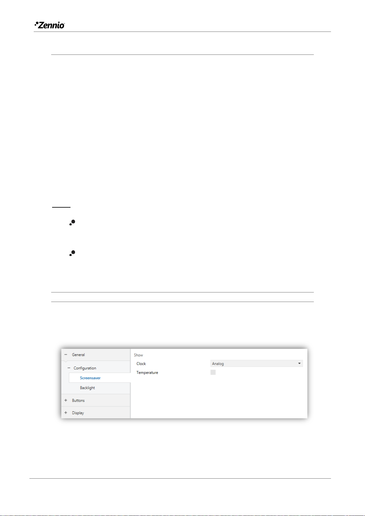
2.1.1.2 SCREENSAVER
The screensaver is a special page that will only be shown after a period of inactivity,
configurable by parameter.
It is possible to choose whether the time is to be displayed, by means of an analogue
clock or by means of a digital clock, the current temperature or, only if a digital clock is
chosen, both (which will be displayed alternately every 5 seconds).
To exit the screen saver, press on the screen or move closer to the screen if the
proximity sensor is activated. It can be set by parameter if, while the screen saver is
active, pressing the touch panel will only cause the screen saver to be interrupted, or if
the action corresponding to the button pressed must also be executed (see section
2.1.1).
Notes:
When showing the welcome greeting (see section 2.1.2.2), screensaver will
not become active.
When screensaver will be active and a pop-up will be active (see touch
locking 2.1.1.3, cleaning function 2.1.2.1 or welcome greeting 2.1.2.2) this
pop-up will become show up over screensaver.
PARAMETRIZACIÓN ETS
After enabling "Screensavers" from the "Configuration" tab (Section 2.1.1) a new tab is
added to the left tree:
Figure 4. Configuration – Screensaver
Page 13
Flat 55 Display
http://www.zennio.com Technical Support: http://support.zennio.com
13
Clock [Disabled / Digital / Analog]: determines whether an analog or digital
clock is displayed or not. If “Analog” is selected, the parameter
“Temperature” cannot be enabled.
Temperature [enabled/disabled]: determines whether to display the current
temperature or not.
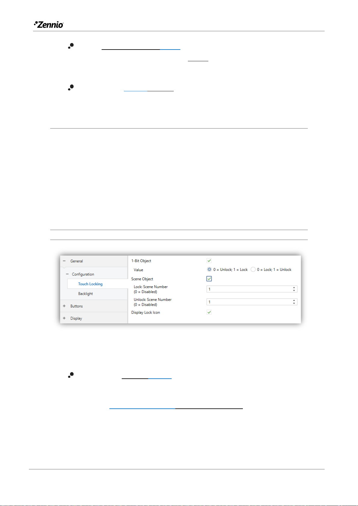
2.1.1.3 TOUCH LOCKING
The touch panel of Flat 55 Display can be optionally locked and unlocked anytime by
writing a configurable one-bit value to a specific object provided for this purpose. It can
also be done through scene values.
While locked, user presses on the touch buttons will be ignored: no actions will be
performed when the user presses on any of the controls. However, if configured, an
icon will be shown on the display for three seconds if the user touches a button during
the lock state.
ETS PARAMETERISATION
Figure 5. Configuration - Touch Locking
In this tab you can configure the blocking of the presses on the display.
1-Bit Object [disabled/enabled]: enables the 1-bit object “[General] Touch
Locking” to trigger the touch lock.
Value [0 = Unlock, 1 = Lock / 0 = Lock, 1 = Unlock]: parameter to select
which value should trigger which action when received through the
indicated object.
Page 14

Flat 55 Display
http://www.zennio.com Technical Support: http://support.zennio.com
14
Scene Object [disabled/enabled]: enables the touch locking and unlocking
when receiving the configured scene value through the object (“[General]
Scene: receive”).
Lock: Scene Number (0 = Disabled) [0/1…64]: scene number that locks
the touch.
Unlock: Scene Number (0 = Disabled) [0/1…64]: scene number that
unlocks the touch.
Display Lock Icon [disabled/enabled]: sets whether to display a padlock icon
in the centre of the screen when the device is locked and the user attempts to
touch a button.
2.1.1.4 AMBIENT LUMINOSITY SENSOR
Flat 55 Display incorporates a luminosity sensor to receive and monitor ambient
brightness measurement.
Please refer to the specific manual “Luminosity and Proximity Sensor” (available in
the Flat 55 Display product section at the Zennio homepage, www.zennio.com) for
detailed information about the functionality and the configuration of the related
parameters.
2.1.1.5 SOUNS
Flat 55 Display emits 3 types of sounds, depending on the action performed:
Press Confirmation: short beep indicating that the user has pressed a
button. This only applies to step controls, i.e., controls that walk through a
certain range of values and that do not send a value after every touch, but
only the final value after the last press. For this action, the user can choose
between two different sounds.
Sending Confirmation: a slightly longer and sharper beep than the previous
one. It indicates the sending of an object to the bus as a result of a press.
Alert notification: high-pitched sound with high volume, which is reproduced
intermittently in exceptional cases. Each case is specified in its corresponding
section.
Page 15

Flat 55 Display
http://www.zennio.com Technical Support: http://support.zennio.com
15
Note: the range of sounds emitted when these actions are performing will be
different depending on the sound selected type.
Enabling and disabling the button sounds can be done in parameters or through an
object, being also possible to define in parameters whether the button sounds should
be initially enabled or not.
Note: Under no circumstances the alarm or the ring tone will be muted.
ETS PARAMETERISATION
After enabling the “Custom” configuration of “Sounds” from “Configuration” screen (see
section 2.1.1), a new tab will be incorporated into the tree on the left.
The initial configuration of this screen is equivalent to the default setting. However, the
following parameters can be customized:
Figure 6. Configuration - Sounds.
Sound Type [Sound 1 / Sound 2]: parameter to select which sounds range
incorporates the device.
Enable Button Sound [enabled/disabled]: enables or disables the acoustic
signals when the actions derived from the button clicks are executed. If
enabled, makes it possible to disable / resume the button beeping function in
runtime by writing to a specific object (“[General] Sounds – Disabling
Button Sound”) and the following parameters will appear:
Page 16

Flat 55 Display
http://www.zennio.com Technical Support: http://support.zennio.com
16
Button Sound After ETS Download [enabled/disabled]: sets whether the
button beeping function should start up enabled (default option) or
disabled after an ETS download.
Object Polarity [0 = Disabled, 1 = Enabled / 0 = Enabled, 1 = Disabled]:
parameter to select which value should trigger which action when received
through the indicated object
Object for Doorbell [disabled/enabled]: enables or disables the doorbell
function. If enabled, a specific object (“[General] Sounds - Doorbell”) will be
included into the project topology.
Value [0 = No Action, 1 = Doorbell / 0 = Doorbell, 1 = No Action]:
parameter to select which value should trigger which action when received
through the indicated object.
2.1.2 ADVANCED CONFIGURATION
Tab for the parameterisation of some advanced functions is shown in ETS if enabled
from the “Configuration” tab. These functions are explained next.
ETS PARAMETERISATION
Figure 7. Advanced.
Cleaning Function [disabled/enabled]: enables or disables the “Cleaning
Function” tab. See section 2.1.2.1 for details.
Welcome Greeting [disabled/enabled]: enables or disables the “Welcome
Greeting” tab. See section 2.1.2.2 for details.
Page 17

Flat 55 Display
http://www.zennio.com Technical Support: http://support.zennio.com
17
Welcome Back Object [disabled/enabled]: enables or disables the
“Welcome Back Object” tab. See section 2.1.2.3 for details.
Warning [disabled/enabled]: enables or disables the “Warning” tab. See
section 2.1.2.4 for details.
Object to Change the Temperature Scale [disabled/enabled]: enables the
1-bit object “[General] Temperature Scale”), which permits changing in
runtime the scale of the temperatures that may show on the screen. By
receiving one ‘0’ through this object, the scale will switch to Celsius, while
after receiving one ‘1’ it will switch to Fahrenheit.
The selected scale applies to any temperatures shown on the screen, such
as:
The screensaver temperature.
Indicators of temperature controls linked to a box in the display ([Climate]
Temperature setpoint)
Temperature indicators ([Climate] Temperature).
After enabling this functionality, the following parameter will also appear:
Scale After Programming [Celsius (ºC) / Fahrenheit (ºF)]: sets the scale
in use after download.
Figure 8. Temperature Scale After Programming.
2.1.2.1 CLEANING FUNCTION
This feature is very similar to the touch locking, that is, it locks the touch area, thus
discarding further button touches. The difference is that this function remains active
only during a parameterizable time, and then stops.
This function is intended to let the user clean the touch area with the certainty of not
triggering unwanted actions.
Page 18

Flat 55 Display
http://www.zennio.com Technical Support: http://support.zennio.com
18
A cleaning icon can be shown during the cleaning state. When the timeout is about to
end, it is also possible to make this cleaning icon blink or to make the device beep (or
both).
ETS PARAMETERISATION
After enabling “Cleaning Function” from “Advanced” screen (see section 2.1.2), a new
tab will be incorporated into the tree on the left.
Figure 9. Avanced - Cleaning Function.
Time to Exit Cleaning Status [5...15…65535][s] [1…65535][min/h]: timeout
to deactivate the cleaning function once triggered.
Displayed Cleaning Icon [disabled / enabled]: sets whether to show a
cleaning icon during the cleaning state. When “Display Cleaning Icon” is
selected, the following parameter appears:
Notify Expiration [No / Blink Message / Play Sound / Both]: sets whether
to notify the timeout expiration or not. When any of the three later options
is selected, a new parameter shows up:
Length of the Warning [1...5…65535][s] [1…65535][min/h]: sets the
ahead-time to start the notification prior to the end of the cleaning
function.
The “[General] Cleaning Function” one-bit object triggers the cleaning function when
it receives a “1” from the KNX bus.
Page 19

Flat 55 Display
http://www.zennio.com Technical Support: http://support.zennio.com
19
2.1.2.2 WELCOME GREETING
This function permits showing the user a welcome message of up to four lines of text
on the display, each of which can be object-dependant or set in parameters.
When a “1” is received through the welcome greeting one-bit object, the display will
become blank and show the welcome text. The same will happen if any of the 14-byte
objects that define the text lines receives a new value from the bus.
It is also possible to make the button LEDs flash during the welcome state.
The message disappears when touching the screen or ending the welcome greeting
with the object.
Note: Welcome greeting takes precedence over screensaver. When the welcome
greeting is displayed, the screensaver will be disabled until the first one disappears.
ETS PARAMETERISATION
After enabling “Welcome greeting” (section 2.1.2), a new tab will be incorporated into
the tab tree. A one-bit object named “[General] Welcome Greeting” will also be shown
in the project topology, to trigger the welcome message by sending the value “1” or to
end it by sending the value “0”.
Figure 10. Avanced– Welcome Greeting.
This screen contains the following parameters:
Line X [Fixed / Received from text Object]: sets whether the corresponding
text line will be pre-defined or object-dependent.
If “Fixed” is selected, the following parameter will appear:
Page 20

Flat 55 Display
http://www.zennio.com Technical Support: http://support.zennio.com
20
Text: textbox to enter the desired text for the corresponding line.
If “Received from text Object” is selected, the following parameter will appear:
Run Welcome Greeting with Text Object Update [enabled/disabled]:
allows choosing whether run the welcome greeting when writing on the 14
bytes object “[General] Welcome Greeting – Line X”. Up to four objects
will appear, depending on how many lines have been assigned the
“Received from text Object” option.
LEDs Flashing During Welcome Status [enabled/disabled]: sets whether
the LEDs of the buttons should blink or not during the welcome greeting.
2.1.2.3 WELCOME BACK OBJECT
Flat 55 Display can send a specific object (a one-bit value, a scene value or both,
depending on the parameterisation) to the KNX bus when the user presses a touch
button or when the proximity sensor detects presence (if enabled) after a significant
amount of time since the last touch or detection. Sending it or not can also depend on
an additional, configurable condition consisting in the evaluation of up to five binary
objects.
Any actions that in normal operation may be executed will not be if the welcome back
object is sent to the bus. Thus, if the user presses a button and this causes that the
welcome back object is sent, the normal action of that button will not be triggered.
ETS PARAMETERISATION
After enabling “Welcome Back Object” from “Advanced” screen (see section 2.1.2), a
new tab will be incorporated into the tree on the left.
Figure 11. Avanced - Welcome Back Object.
Page 21

Flat 55 Display
http://www.zennio.com Technical Support: http://support.zennio.com
21
Time to Activate the Welcome Object [1...65535][s] [1…65535][min/h]: sets
the minimum time that should elapse after the last button touch (or presence
detection, when the proximity sensor is enabled) before the next one triggers
the execution of the welcome back function.
Send Object Trigger [Press Button / Detect Presence]: sets whether the
welcome back object is sending after a touch in the screen or when the
proximity sensor detects presence.
Additional Condition: sets if sending the welcome back object should also
depend on an external condition. The option by default is [No Additional
Condition]. The following are available too:
[Do not send unless all additional conditions are 0]: the welcome back
object will only be sent if all the condition objects are found to have the
value “0”.
[Do not send unless all additional conditions are 1]: the welcome back
object will only be sent if all the condition objects are found to have the
value “1”.
[Do not send unless at least one of the additional conditions is 0]: the
welcome back object will only be sent if at least one of the condition
objects is found to have the value “0”.
[Do not send unless at least one of the additional conditions is 1]: the
welcome back object will only be sent if at least one of the condition
objects is found to have the value “1”.
Number of Condition Objects [1…5]: up to 5 objects can be selected for
the additional condition (“[General] Welcome Back Object – Additional
Condition”).
Welcome Back Object (1-Bit) [disabled/enabled]: checkbox to enable the
sending of a 1-bit value (through “[General] Welcome Back Object”) when
the welcome back function is triggered and the condition (if any) evaluates to
true. The desired value should to be set in Value [Send 0 / Send 1]
Welcome Back Object (Scene) [disabled/enabled]: checkbox to enable the
sending of a scene run request (through “[General] Scene: send”) when the
Page 22

Flat 55 Display
http://www.zennio.com Technical Support: http://support.zennio.com
22
welcome back function is triggered and the condition (if any) evaluates to
true. The desired value should to be set in Scene Number [1…64].
2.1.2.4 WARNING
This function is intended for visual and/or audible notification of an important event.
The warning is activated when the configured value is received through a 1-bit object.
The display will show a flashing icon, which may be accompanied by flashing LEDs
and/or a sound, if configured. In addition, the brightness level can be attenuated during
night mode.
The warning can be stopped (muted) by pressing a button. However, as long as the
warning remains active, when the device goes into inactivity, the icon is displayed
again.
The warning is deactivated when the determined value is received through the 1-bit
object, and any notification is no longer displayed.
Note: Warning sound takes precedence over all other sounds.
ETS PARAMETERISATION
After enabling “Warning” from the “Advanced” (section 2.1.2), a new tab will be
incorporated into the tab tree. A one-bit object named “[General] Warning” will also be
shown in the project topology, to start or stop the warning message.
Figure 12. Advanced– Warning.
This screen contains the following parameters:
Page 23

Flat 55 Display
http://www.zennio.com Technical Support: http://support.zennio.com
23
Display Icon [Window Open / Drop-down with icons to be selected]: sets the
icon that will be shown on the display once the warning is activated.
Enable LED Flashing [enabled/disabled]: sets whether the LEDs of the
buttons should blink or not during the warning.
Enable Acoustic Notification [enabled/disabled]: sets whether there will be
an intermittent sound or not during the warning.
Enable Attenuation During Night Mode [enabled/disabled]: sets whether
the brightness will be attenuated or not if the night mode is active during the
warning.
Object Polarity [0 = Stop Warning, 1 = Start Warning / 1 = Stop Warning, 0 =
Start Warning]: parameter to select which value should trigger which action
when received through the indicated object.
Page 24

Flat 55 Display
http://www.zennio.com Technical Support: http://support.zennio.com
24
BUTTONS
2.2.1 CONFIGURATION
Flat 55 Display features four capacitive buttons at the user’s disposal for the
execution of actions. Each will perform a specific function any time, as their functions
do not depend on alternating menus, pages, etc.
Although the four buttons are laid out in the corners of the device, they can act as
single-button controls or in up to two pairs, being possible to combine any two of
them within one pair. The opposite corner buttons cannot be configured as a pair.
All the buttons are identical; this brings a high level of versatility for a wide variety of
applications. The following is a list of the functions that can be assigned to each button.
Disabled (the button will not react to user presses).
Pair Left and Right, or Pair Up and Down, being the function of such pair
one of the following:
Switch.
Two objects (short press / long press).
Dimmer.
Shutter.
Scaling.
Counter.
Enumeration.
Float.
Multimedia.
[Climate] Temperature setpoint.
[Climate] Mode.
[Climate] Fan.
[Climate] Mode Special.
Individual:
LED indicator.
Switch.
Hold & release.
Page 25

Flat 55 Display
http://www.zennio.com Technical Support: http://support.zennio.com
25
Two objects (short press / long press).
Scene.
Scaling constant.
Counter constant.
Float constant.
Dimmer.
Shutter.
Enumeration.
[Climate] Fan.
[Climate] Mode.
[Climate] Mode Special.
Room State.
Apart from the button function itself, the integrator can select the desired behaviour of
the button LEDs. The different illumination modes have been detailed in ANNEX I. LED
Illumination Modes.
The next sections explain the configuration involved for each of the above functions.
Page 26

Flat 55 Display
http://www.zennio.com Technical Support: http://support.zennio.com
26
ETS PARAMETERISATION
An independent tab for the parameterization of the buttons is shown in ETS by default,
initially containing only a sub-tab named “Configuration”.
Figure 13. Buttons – Configuration
One drop-down list with the following options is shown per button.
[Disabled]. See section 2.2.2 for details.
[Individual]. Selecting this option brings a new tab (“Button X”), which will
make it possible to configure the functionality of that particular touch
button. See section 2.2.3 for details.
[Pair X]. Sets that this touch button will belong to a two-button control.
Once one pair has been assigned to two buttons (and not before), a new
tab (Pair Up / Down / Left / Right) will show up in the tab tree, in order to
configure the desired functionality. See section 2.2.4 for details.
LED Illumination Control (All buttons): jointly sets the LEDs illumination
behaviour. The options are (please refer to ANNEX I. LED Illumination Modes
for details):
Page 27

Flat 55 Display
http://www.zennio.com Technical Support: http://support.zennio.com
27
[Disabled]
[Regular]
[State-Dependent (where available)]
[State-Dependent (where available) (both LEDs)]
[Dedicated Object]
[Configure every button (pair) separately]: in case of selecting the last
option, there will be a specific parameter for each control to specifically
select the desired behaviour of the LED (or LEDs):
If at least one two-button control is being configured (either Pair Left, Right or Pair Up,
Down), an additional parameter will be available. The options are:
Action of the pair buttons (All pairs): to determine an operation criterion:
[Left = Off/Down/Decrement; Right = On/Up Increment]
[Right = Off/Down/Decrement; Left = On/Up Increment]
[Every button pair is configured separately]: there will be a specific
parameter in every two-button control for specifically selecting the desired
behaviour.
2.2.2 DISABLE
While a button stays disabled, it will not be functional: touching on it will not cause the
execution of actions, nor will make the associated LED light.
ETS PARAMETERISATION
While a button stays disabled, it will not be functional: touching on it will not cause the
execution of actions, nor will make the associated LED light.
2.2.3 INDIVIDUAL
Buttons configured to work as individual (separate) controls can be assigned any of the
following control functions:
LED Indicator: user presses will not trigger any function although the LED
will turn on or off depending on the values received from the bus.
Page 28

Flat 55 Display
http://www.zennio.com Technical Support: http://support.zennio.com
28
Switch: whenever the user touches the button, a binary value will be sent to
the KNX bus. This value is configurable and may be 0 or 1, or alternate with
every touch according to the sequence 1 0 1 …
Under a “State-dependent” LED illumination, the LED will remain on/off
according to the current state (on/off) of the object.
Hold & Release: as soon as the user touches the button, a binary value will
be sent to the KNX bus. And as long as the user releases the button, another
value will be sent through the same object.
The “State-dependent” LED mode is not available for this function.
Two Objects (short press/long press): specific binary values will be sent
both after a short or a long press (a different object will be used in each
case).
Under a “State-dependent” LED illumination, the LED will remain on/off
according to the current state (on/off) of either one object or the other, which
can be configured in parameters. However, if LED Illumination Control (All
Buttons) has been set to “State-dependent (where available)”, only the short
press object will apply.
Scene: after the user touches the button, an order to run a specific scene
(configurable) will be sent to the bus. If enabled in parameters, orders to save
the scene can also be sent to the bus after a three-second press on the
button.
The “State-dependent” LED mode is not available for this function.
Scaling constant: sends a percentage value (configurable) to the bus when
the user touches the button.
Under a “State-dependent” LED illumination, the LED will remain on/off
depending on whether the current value of the object matches the one
parameterised. This object can also be written from the bus, which will update
the LED according to the new value.
Page 29

Flat 55 Display
http://www.zennio.com Technical Support: http://support.zennio.com
29
Counter constant: sends an integer value (configurable) to the bus when the
user touches the button. This value can be one-byte or two-byte sized, as
well as signed or unsigned. The available ranges are shown next:
1-byte
2-byte
Unsigned
0 – 255
0 – 65535
Signed
-128 – 127
-32768 – 32768
Table 1 Value range – Counter type constant
The “State-dependent” LED illumination mode is analogous as for the Scaling
Constant function.
Float constant: sends a two-byte floating point value (configurable) to the
bus when the user touches the button. The available range is -671088.625 to
670760.9375.
The “State-dependent” LED illumination mode is analogous as for the
Scaling Constant and Counter Constant functions.
Dimmer: implements a one-button light control that sends orders to the KNX
bus, which can then be executed by light dimmers. These orders consist in:
Switch-on/Switch-off orders (on short presses).
Step dimming orders (on long presses) and the subsequent stop order
after the button is released.
Being a one-button control, the switch orders will alternate (on/off) for every
short press, and so will do the step dimming orders (increase/decrease) for
every long press. However, there are some exceptions:
On a long press: an increase dimming order will be sent if the light is found
to be off (according to the status object). On the other hand, a decrease
order will be sent if it is found to be 100%.
On a short press: a switch-on order will be sent if the light is found to be off
(according to the status object). On the other hand, a switch-off order will
be sent if it is found to be on (value greater than 0%).
Note that the device considers that the current light level is the value of a
specific one-byte object provided to be written from the KNX bus (i.e., to
Page 30

Flat 55 Display
http://www.zennio.com Technical Support: http://support.zennio.com
30
receive feedback from the dimmer). This object is internally updated after a
short or long press but linking it to the real dimmer status is highly advisable.
Under a “state-dependent” LED illumination, the LED will remain on/off
according to the value of the aforementioned status object (i.e., off when the
value is 0% and on in any other case).
Shutter: implements a one-button shutter control that sends orders to the
KNX bus, which can then be executed by an actuator. Two control types can
be configured:
Standard: the device will react to both long and short presses, being
possible to send the bus the following commands:
Move (raise/lower) orders (on long presses).
Stop/Step orders (on short presses).
Being a one-button control, the direction of the motion will alternate
(upwards/downwards) for both the move and the step orders after every
long press. However, there are some exceptions to this alternation:
On a short press: a step-up order will be sent if the last long press
made the shutter move up, or if the current position is found to be
100%. On the other hand, a step-down order will be sent if the last long
press made the shutter move down or if the current position is found to
be 0%.
On a long press: a move-up order will be sent if the last short press
caused a step-down order or if the current position is found to be 100%.
On the other hand, a move-down order will be sent if the last short
press caused a step-up order or if the current position is found to be
0%.
As usual in the KNX standard, stop/step orders are interpreted by the
actuators as a request to move the slats one step up or down (in case the
shutter is still) or as a request to interrupt the motion of the shutter (in case
it is already moving up or down).
Hold & Release: the device will send an order to move the shutter when
the button is touched, and the order to stop it as soon as it is released.
Page 31

Flat 55 Display
http://www.zennio.com Technical Support: http://support.zennio.com
31
Therefore, short or long touches have the same effect: the shutter will
remain in motion as long as the user keeps holding the button.
The direction of this motion (upwards or downwards) will alternate with
every touch, according to the following sequence: downwards upwards
downwards … However, there are some exceptions to this
alternation:
If the position of the shutter is found to be 0%, the next order will lower
the shutter.
If the position of the shutter is found to be 100%, the next order will
raise the shutter.
Flat is aware of the current position of the shutter through a specific object
which should be linked to the analogous object of the shutter actuator, in
order to receive feedback. This object is initialised with value “50%” after a
download or a bus failure; therefore, the actuator is required to update it with
the real value after the bus recovery.
The “state-dependent” LED illumination mode is not available for this
function.
Enumeration: sends one-byte (unsigned) numeric value to the KNX bus from
a list of up 6 different values. Each press advances the list to the next item.
This control provides a parameter to link the control to a box on the screen
so that the current numeric value is displayed at all times on the screen.
The “State-dependent” LED mode is not available for this function.
[Climate] Fan: pressing one of the two buttons will make Flat 55 Display
send a binary value to the bus that allows changing the fan speed (up to five
levels available). This value can be either binary (increase / decrease
orders), scaling (0% - 100%) or enumerated.
Furthermore, it is possible to configure the speed 0 as an additional fan level,
and/or another level to activate the Auto mode.
Page 32

Flat 55 Display
http://www.zennio.com Technical Support: http://support.zennio.com
32
The order to activate the auto mode can be sent over a one-bit object
independent from the fan control object, or alternatively consist in the speed
level 0. In the latter case, one ‘0’ will trigger the Auto mode.
The table below shows the relation between the scaling values and the
enumeration values, depending on the number of speed levels configured
(note that if the Auto mode or the speed level 0 are allowed one more level is
added, corresponding to value 0).
% Values based on fan levels
Speed levels
1 2 3 4 5
Enumeration value
1
100
50,2
33,3
25,1
20 2 -
100
66,7
50,2
40 3 - - 100
75,3
60 4 - - -
100
80 5 - - - - 100
Table 2 Fan levels.
For the scaling and enumeration controls, the object is sent to the bus
slightly delayed once the desired value has been set by the user. For these
two cases it is possible to link the control with a box in the display in
order to show the current value on the display.
Under a “state-dependent” LED illumination, the LED will remain on/off
according to the current state of the fan.
[Climate] Mode: pressing the button will make Flat 55 Display send climate
mode values to the bus. Two mode control types are possible: Heat / Cool
and Extended (HVAC).
As above, linking the control to a box in the display in order to show the
current mode on it is possible (only for Extended mode).
The “State-dependent” LED mode is not available for this function.
[Climate] Special Mode: lets the user sequentially commute between the
different special climate mode: Auto, Comfort, Standby, Economy and
Building Protection. This function is analogous to the modes control in its
Extended version.
Page 33

Flat 55 Display
http://www.zennio.com Technical Support: http://support.zennio.com
33
Room State: allows controlling the room states (normal, make-up request, do
not disturb). User can switch the state between normal and do not disturb or
make-up request. Configuring by parameter if will activate do not disturb or
make-up request state will be necessary.
Depending on the parameterisation and the current value of object, after a
short press, the following values will be transmitted:
State
Current Object Value
Transmitted Value
Make-Up Request
Do Not Disturb / Normal
Make-Up Request
Make-Up Request
Normal
Do Not Disturb
Normal / Make-Up Request
Do Not Disturb
Do Not Disturb
Normal
Table 3 Room States
If the LED illumination is “State-dependent”, LED will light up when the
current object value coincides with the parameterized value.
ETS PARAMETERISATION
When an individual button has been enabled, a specific tab (“Button In”) becomes
available under “Buttons” in the tree on the left.
The main parameter to be configured is:
Function [LED indicator / Switch / Hold & Release / Two Objects (short press
/ long press) / Scene / Scaling constant / Counter constant / Float constant /
Dimmer / Shutter / Enumeration / [Climate] Fan / [Climate] Mode / [Climate]
Special Mode / Room State]: sets the desired function for the button.
Depending on the function, some more parameters are involved (as
described next). Please note that in the next pages “[In]” is used as a general
notation for the communication objects, where “n” depends on the particular
button pair.
LED Illumination Control: sets the behaviour of the LEDs on the buttons.
Depending on the type of control selected for each button, the options may
be: [Regular / State-Dependent / Dedicated object]. (See ANNEX I. LED
Illumination Modes for details)
Page 34

Flat 55 Display
http://www.zennio.com Technical Support: http://support.zennio.com
34
In case of selecting “Dedicated Object”, the object “[Btn] [In] LED On/Off”
will be included in the project topology and a new parameter:
Value [0 = Off; 1 = On / 0 = On; 1 = Off] to select the value to switch off
and on the LED shows up.
Figure 14 LED illumination control - Dedicated object.
Note: this parameter will remain hidden unless having selected “Configure
every button (pair) separately” in “LED Illumination Control (All Buttons)”
(see 2.2.1).
Moreover, the textbox INFO allows changing the default name of the tab in the left
menu, as shows the following figure.
Figure 15. Individual Button.
LED indicator
Figure 16. Individual Button – LED indicator.
Page 35

Flat 55 Display
http://www.zennio.com Technical Support: http://support.zennio.com
35
Value [0 = Off; 1 = On / 0 = On; 1 = Off]: sets the behaviour of the LED of
the button. The options are similar to those of the dedicated-object LED
illumination available for other control types.
Note: this parameter does not depend on the option selected for LED
Illumination Control (All Buttons) (see section 2.2.1).
After assigning this function to the button, object “[Btn] [In] LED On/Off” is included in
the project topology, so that the values that determine the state of the LED at a given
time can be received from the bus.
Switch
Figure 17. Individual Button - Switch.
Action [Send 0 / Send 1 / Toggle 0/1]: sets the value to be sent to the bus
(through object “[Btn] [In] Switch”) when the user touches the button.
LED Illumination Control [Regular / State-Dependent / Dedicated object].
Hold & Release
Figure 18. Individual Button - Hold & Release.
Action on Hold [Send 0 / Send 1]: sets the value to be sent to the bus
(through “[Btn] [In] Hold & Release”) when the user touches the button.
Action on Release [Send 0 / Send 1]: sets the value to be sent to the bus
(again, through “[Btn] [In] Hold & Release”) when the user stops touching
the button.
Page 36

Flat 55 Display
http://www.zennio.com Technical Support: http://support.zennio.com
36
LED Illumination Control [Regular / Dedicated object].
Two Objects (Short Press/Long Press)
Figure 19. Individual Button - Two Objects (Short Press / Long Press).
Action on Short press [Send 0 / Send 1 / Toggle 0/1 / Send 1-byte
Unsigned Int Value]: sets the value to be sent to the bus (through “[Btn]
[In] Two Objects - Short Press”) when the user short-presses the button.
In case of selecting the latter, an additional parameter (“Value”) will be
displayed to enter the desired one-byte value [0…255].
Action on Long press [Send 0 / Send 1 / Toggle 0/1 / Send 1-byte
Unsigned Int Value]: sets the value to be sent to the bus (through “[Btn]
[In] Two Objects - Long Press”) when the user long-presses the button.
In case of selecting the latter, an additional parameter (“Value”) will be
displayed to enter the desired one-byte value [0…255].
Long Press Threshold Time [4…6…50] [ds]: sets the minimum time the
user should hold the button in order to consider it a long press.
LED Illumination Control [State dependent / Regular / Dedicated object]:
Selecting “State dependent” brings an additional parameter:
State Object [Short Press Object / Long Press Object] to make the state
of the LED correspond either to object “[Btn] [In] Two Objects - Short
press” or to object “[Btn] [In] Two Objects - Long press” respectively.
Page 37

Flat 55 Display
http://www.zennio.com Technical Support: http://support.zennio.com
37
Scene
Figure 20. Individual Button - Scene.
Action [Run / Run and Save]: sets whether the value to be sent to the
KNX bus when the user touches the button will always be a scene run
request or –depending on the length of button press– a scene run or save
request (3s press).
Scene number [1…64]: number of the scene to be sent to the bus, both in
the case of the run requests and the save requests.
Object to Use [General Scene Object / Individual Control Scene Object]:
commands are sent via the general scene object (“[General] Scene:
Send”) or through a control object (“[Btn][In] Scene: Send”).
LED Illumination Control [Regular / Dedicated object].
Scaling Constant / Counter Constant / Float Constant
Figure 21. Individual Button - Scaling Constant
Object Value: sets the value to be sent to the KNX bus when the user
touches the button. The available range and the object through which the
value is sent depend for each case, as the table below shows.
Page 38

Flat 55 Display
http://www.zennio.com Technical Support: http://support.zennio.com
38
In case of selecting Counter Constant, two specific parameters (“Size” and
“Signed”) will be displayed to respectively define the size of the constant and
whether it is a signed value or an unsigned value. Depending on that, the
range and the name of the object will vary.
Function
Size
Sign
Object Value
Object Name
Scaling
1-Byte [0…100]
[Btn][In] 1-Byte Scaling Value
Counter
1-Byte
Signed
[-128…0…127]
[Btn][In] 1-Byte Signed Int Value
Unsigned
[0…255]
[Btn][In] 1-Byte Unsigned Int Value
2-Bytes
Signed
[-32768…32767]
[Btn][In] 2-Byte Signed Int Value
Unsigned
[0…65535]
[Btn][In] 2-Byte Unsigned Int Value
Float
2-Bytes
[-671088.64…0…670760.96]
[Btn][In] 2-Byte Float Value
Table 4 Constant type numerical control.
LED Illumination Control [Regular / State dependent / Dedicated object].
Dimmer
Figure 22. Individual Button - Dimmer
The (alternating) switch orders will be sent through the “[Btn] [In] Light - On/Off” onebit object, while the (alternating) increase/decrease/stop orders will be through the
“[Btn] [In] Light - Dimming” four-bit object.
On the other hand, the “[Btn] [In] Light - Dimming (Status)” one-byte object may be
linked to the light level status object of the dimmer.
The parameters for this function are:
Dimming Step [100% / 50% / 25% / 12.5% / 6.25% / 3.1% / 1.5%]: defines
the dimming step to be sent (through “[Btn] [In] Light - Dimming”) to the
light dimmer with every long press.
Page 39

Flat 55 Display
http://www.zennio.com Technical Support: http://support.zennio.com
39
Note: since dimmers typically do not apply the new light level immediately
(i.e., the step is performed progressively) and since Flat 55 Display sends
an order to interrupt the step dimming once the user releases the button, it
is advisable to configure a step of 100%. This way, the user can perform
any dimming step by simply leaving the button pressed and then releasing
it, without needing to make successive button presses.
LED Illumination Control [Regular / State-Dependent / Dedicated object].
Shutter
Figure 23. Individual Button - Shutter
The (alternating) move up/down orders will be sent through the “[Btn] [In] Shutter Move” one-bit object, while the (alternating) step up/down orders will be through the
“[Btn] [In] Shutter - Stop / Step” one-bit object.
Additionally, a one-byte object (“[Btn] [In] Shutter Position”) is provided to link it to
the position status object of the shutter actuator (in fact, this object is only intended to
receive values from the bus, not to send them).
The parameters for this function are:
Type [Standard/Hold & Release]: sets the desired control type:
[Standard]: a long press will make the device send to the KNX bus an
order to start moving the shutter (upwards or downwards, depending on
the button), while a short press will make it send a stop order.
[Hold & Release]: as soon as the button is held, the device will send the
KNX bus an order to start moving the shutter (upwards or downwards,
depending on the button). After the button is released, it will send an
order to stop the shutter.
LED Illumination Control [Regular / Dedicated object].
Page 40

Flat 55 Display
http://www.zennio.com Technical Support: http://support.zennio.com
40
Enumeration
This control is analogous to the Switch control, with the particularity that the
communication object will be one byte (“[Btn][In] Enumeration”) and that up to 6
states can be distinguished depending on the object value.
Figure 24. Individual Buttons – Enumeration.
# Enums [1…6]: number of states that will be distinguished. For every
distinguished state, the following parameter will become available:
Value j [0…255]: numerical value that will be sent through the control
object when the user, after pressing the buttons, sets the control to
state j. The actual sending will not be performed until 1.5 seconds after
the last press.
Link the control with a box in the display: sets the area of the display
where to show the indicator of this control, i.e., the current numeric value.
See section 2.3 for details.
LED Illumination Control [Regular / Dedicated object].
[Climate] Fan
When this function is assigned to the button, one object (“[Btn][In] Fan Control”) for
each type of control and 1-byte status object (“[Btn][In] Fan Indicator”) are enabled.
The status object (which must be linked to the status object of the fan actuator) will
indicate, in percent, the value of the current speed level.
Page 41

Flat 55 Display
http://www.zennio.com Technical Support: http://support.zennio.com
41
Figure 25 Individual Buttons – [Climate] Fan
Speed Levels [1…5]: allows selecting the speed levels available for
control.
Control Type: sets the type of the communications objects to control the
fan level.
[1 bit (decrease/increase)]: orders of speed increase/decrease are sent
through the one-bit object “[Btn] [In] Fan Control (Type: 1-Bit)”.
[Scaling]: scaling values are sent through the one-byte object “[Btn] [In]
Fan Control (Type: Scaling)”.
[Enumeration]: integer values are sent through the one-byte object
“[Btn] [In] Fan Control (Type: Enumeration)”.
Cyclical [enabled/disabled]: sets whether scrolling through the speed
levels is circular or not. If checked, a press switches to the minimum level.
On the other hand, if cyclical is disabled, the level increases to the last one
and then decrease. At levels other than the first and last, the last action
(increase or decrease) is maintained until reaching the first or last.
Auto Mode [enabled/disabled]: sets whether the fan Auto mode will be
available or not. If checked, the following parameters are also shown.
Dedicated Object for Auto Mode [enabled/disabled]: sets how the
Auto mode should be activated. In the absence of a dedicated object,
the Auto fan mode will be activated by switching to fan level 0.
Page 42

Flat 55 Display
http://www.zennio.com Technical Support: http://support.zennio.com
42
Figure 26. Individual Buttons – [Climate] Fan – Auto Mode.
In this case (supposing that “Speed Levels” has been set, for instance, to
“3”), the fan levels that can be navigated through short presses are:
Auto Mode ( 0 )
Minimum
Medium
Maximum
On the other hand, marking the checkbox enables the one-bit object “[Btn]
[In] Fan Control – Auto Mode”, which will trigger the Auto mode when it
receives the value “1” (or “0”, depending on the subsequent parameter,
“Value to Set the Auto Mode” [Send 0 / Send 1]).
Figure 27. Individual Buttons – [Climate] Fan – Dedicated Object for Auto Mode.
However, two alternative (and mutually exclusive) methods are possible to
activate this mode:
By short press: Auto mode can be reached as a further level above the
maximum one. In this case the fan levels activated by short presses are
(note that speed 0 is optional):
( 0 )
Minimum
Medium
Maximum
Auto Mode
By long press on any of the buttons of the control (requires checking
“Long Press to Activate Auto Mode” [enabled/disabled]).
A further long press deactivates back the Auto mode and resumes the
previous fan level. Instead, a short press deactivates the Auto mode
Page 43

Flat 55 Display
http://www.zennio.com Technical Support: http://support.zennio.com
43
and switches to the next level (or previous, depending on the button). In
this case the fan levels reachable through short presses are (speed 0
is optional):
(The Auto mode here is only activated by long press).
Allow speed 0 [enabled/disabled]: sets whether the speed level 0 will be
present or not. When the “Auto Mode without a dedicated object” has
been configured, this option will be necessarily activated.
Link the control with a box in the display: sets the area of the display
where to show the indicator of this control, i.e., the current fan speed. The
selected box must be configured with the same data type (see section 2.3 for
details).
Note: this parameter is only available for Scaling or Enumeration control
types.
LED Illumination Control [Regular / State-dependent / Dedicated Object].
[Climate] Mode
Figure 28. Individual Buttons – [Climate] Mode (Heat/Cool)
Mode Type: sets mode control type:
[Heat/Cool]: Selecting this type of mode control turns the box into a control
which will activate the Heat or Cool mode.
One communication object is also enabled: the “[Btn][In] (Climate) Mode”
control and status object. Depending on the mode selected by the user,
the control object will be sent to the bus a certain value.
( 0 )
Minimum
Medium
Maximum
Page 44

Flat 55 Display
http://www.zennio.com Technical Support: http://support.zennio.com
44
Mode
Sent Value
Cool
0
Heat
1
Table 5. Heat/Cool Mode vs. Object Value.
[Extended]: pressing on the button will make Flat 55 Display walk through
the different HVAC modes and send a one-byte value to the bus according
to the selected mode.
Up to five modes [Heat / Cool / Auto / Fan / Dry] are available, each of
which can be in ETS by means of the proper checkbox, which permits
setting which of all the five extended modes will be included into the
sequential scrolling implemented by the buttons.
Figure 29. Individual Buttons – [Climate] Mode (Extended).
When this type of mode control is assigned to the box, one 1-byte
communication object is enabled: the “[Btn][In] (Climate) Mode –
Extended” control and status object. Depending on the mode selected by
the user, the control object will be sent to the bus a certain value.
Mode
Sent Value
Auto
0 (0x00)
Heat
1 (0x01)
Cool
3 (0x03)
Fan
9 (0x09)
Dry
14 (0x0E)
Table 6. HVAC Mode vs. Object Value.
Page 45

Flat 55 Display
http://www.zennio.com Technical Support: http://support.zennio.com
45
Link the control with a box in the display: sets the area of the display
where to show the indicator of this control, i.e., the current numeric value.
The selected box must be configured with the same data type (see section
2.3 for details).
Note: this option is only available for Extended mode type.
LED Illumination Control [Regular / Dedicated Object].
[Climate] Special Mode
This control is exactly the same as [Climate] Mode in its Extended version, but with
the modes: Auto, Comfort, Standby, Economy, Building Protection.
The climate mode will be controlled through the object “[Btn][In] (Climate) Special
Mode Control”.
Figure 30. Individual Buttons - [Climate] Special Mode Control.
Room State
When this function is assigned to the button, the object for the control ““[Btn][In] Room
State” is enabled. This object will also be a status indicator.
Figure 31. Individual Buttons – Room State.
Page 46

Flat 55 Display
http://www.zennio.com Technical Support: http://support.zennio.com
46
State [Make-up Request / Do not Disturb]: sets the desire function.
LED Illumination Control [Regular / State-Dependant / Dedicated Object].
Page 47

Flat 55 Display
http://www.zennio.com Technical Support: http://support.zennio.com
47
2.2.4 PAIR
Buttons configured to work as a joint control can be assigned the following functions:
Switch: Pressing one of the two buttons will make Flat 55 Display send a
binary value to the bus, while pressing on the other will make it send the
inverse binary value. It is possible to configure which one does what.
Under a “state-dependent” LED illumination (see ANNEX I. LED Illumination
Modes), the LED of the corresponding button will remain on/off according to
the current state (on/off) of the switch.
On the other hand, under a “state-dependent (both LEDs)” LED illumination,
both of them will remain on while the switch is in the “on” state, and off while
in the “off” state.
Two objects (short press/long press): control for sending specific binary
values both after a short or a long press on any of the two. Different objects
will be used for the short and long presses.
Moreover, it is possible (in parameters) to make the “state-dependent” and
“state-dependent (both LEDs)” LED illumination modes (see ANNEX I. LED
Illumination Modes) depend on either one object or the other. However, if
“LED Illumination Control (All Buttons)” (section 2.2.1) has been set to
“state-dependent (where available)” only the short press object will be
considered.
Dimmer: sends a switch-on order to the bus, while doing so on the other
button will make it send a switch-off order. Long presses will make it send a
step dimming order (the value of which is configurable) to make a dimmer
increase or decrease the light level (and a stop order as soon as the user
releases the push button). Setting which button does what is possible.
Under a “state-dependent” LED illumination (see ANNEX I. LED Illumination
Modes), the LED of the corresponding button will remain on/off according to
whether the current value of the light level status object (which should be
updated by the actual dimmer) is greater than 0% or not.
On the other hand, under a “state-dependent (both LEDs)” LED illumination,
both together will remain on or off depending on such value.
Page 48

Flat 55 Display
http://www.zennio.com Technical Support: http://support.zennio.com
48
Shutter: This option permits making use of the two buttons to control a
shutter actuator connected to the bus. Two alternative control methods are
possible:
Standard: a long press will make the device send to the KNX bus an order
to start moving the shutter (upwards or downwards, depending on the
button), while a short press will make it send a stop order (which will be
interpreted as an order to step up or to step down –depending on the
button– if the shutter was not in motion and such function is available).
Hold & Release: as soon as the button is held, the device will send the
KNX bus an order to start moving the shutter (upwards or downwards,
depending on the button). Once the button is released, it will send an order
to stop the shutter.
The “state-dependent” and “state-dependent (both LEDs)” LED illumination
modes are not available for this function. See ANNEX I. LED Illumination
Modes for details.
Scaling, Counter, Float: the touches over the buttons will trigger the sending
of a certain numerical value to the bus (this value will be progressively
increased or decreased every time the user touches one button or the other)
through the control object.
These controls provide a parameter to link them to a box in the display so the
current numerical value is shown on the display. The screen will reflect the
new values as the user touches the buttons, however values are actually sent
to the bus 1.5 seconds after the last press.
The “state-dependent” and “state-dependent (both LEDs)” LED illumination
modes are not available for this function. See ANNEX I. LED Illumination
Modes for details.
Enumeration: pressing the buttons will make Flat 55 Display send a one-
byte (unsigned) value to the bus. There were up to 6 different values.
Successively pressing on the buttons will make Flat 55 Display walk through
the different values.
Page 49

Flat 55 Display
http://www.zennio.com Technical Support: http://support.zennio.com
49
As the above functions, this type of control provides parameter to link the
control with a box in the display in order to show the current value on the
display. Again, values are sent to the bus 1.5 seconds after the last press.
The “state-dependent” and “state-dependent (both LEDs)” LED illumination
modes are not available for this function. See ANNEX I. LED Illumination
Modes for details.
[Climate] Temperature setpoint: allows controlling the temperature setpoint
of an external thermostat by means of a button pair and the display.
This function can also be linked to a box in the display in order to show the
current setpoint value. The box will reflect the value (in ºC or ºF, depending
on the selected scale; see section 2.1.2) of the status object, which gets
automatically updated after sending control orders (that is, after pressing the
buttons), being even possible to receive values from the bus, for example,
from the corresponding setpoint status object from the external thermostat.
The “state-dependent” and “state-dependent (both LEDs)” LED illumination
modes are not available for this function. See ANNEX I. LED Illumination
Modes for details.
[Climate] Mode: pressing one of the two buttons will make Flat 5 Display
send climate mode values to the KNX bus. This function is analogous to the
mode control on individual button described in section 2.2.3.
[Climate] Fan: implements a two-button fan control which sends the KNX
bus values in order to change the fan speed level. This function is analogous
to the ventilation control on individual button described in section 2.2.3.
[Climate] Special Mode: lets the user sequentially commute between the
different special climate mode: Auto, Comfort, Standby, Economy and
Building Protection. This function is analogous to the special mode control on
individual button described in section 2.2.3.
Page 50

Flat 55 Display
http://www.zennio.com Technical Support: http://support.zennio.com
50
ETS PARAMETERISATION
After two buttons have been assigned to a particular pair, a specific tab (“Pair X”)
becomes available under “Buttons” in the tab tree.
The main parameter that needs to be configured is:
Function [Switch / Two Objects (Short Press/Long Press) / Dimmer / Shutter
/ Scaling / Counter / Enumeration / Float / [Climate] Temperature Setpoint /
[Climate] Mode / [Climate] Fan / [Climate] Mode Special]: sets the desired
function for the button.
Depending on the function, some more parameters are shown, as described
next. Please note that in the next pages the general notation “[X]” is used for
the name of the communication objects, as “X” depends on the button pair.
LED Illumination Control: sets the behaviour of the LEDs on the buttons.
Depending on the type of control selected for each buttons pair, the options
may be: [Regular / State-Dependent / State-dependent (Both LEDs) /
Dedicated object]. (See ANNEX I. LED Illumination Modes for details).
In case of selecting “Dedicated Object”, the object “[Btn] [PX] LED On/Off”
will be included in the project topology and a new parameter:
Value [0 = Off; 1 = On / 0 = On; 1 = Off] to select the value to switch off
and on the LED shows up.
Figure 32 LED illumination control - Dedicated object.
Note: this parameter will remain hidden unless having selected “Configure
every button (pair) separately” in “LED Illumination Control (All Buttons)”
(see 2.2.1).
Moreover, the textbox INFO allows changing the default name of the tab in the left
menu, as shows the following figure.
Page 51

Flat 55 Display
http://www.zennio.com Technical Support: http://support.zennio.com
51
Figure 33. Pair A.
Buttons configured to work as a joint control can be assigned the following functions:
Switch
Figure 34. Pair Buttons – Switch
Action [Left = 0; Right = 1 / Right = 0; Left = 1]: assigns each of the two
buttons the value to be sent through “[Btn] [PX] Switch”.
Note: this parameter will remain hidden unless having selected “Every button
pair is configured separately” in Action of the pair buttons (see section
2.2.1).
LED Illumination Control [Regular / State-dependent / State-dependent
(both LEDs) / Dedicated Object].
Page 52

Flat 55 Display
http://www.zennio.com Technical Support: http://support.zennio.com
52
Two objects (short press / long press)
Figure 35 Pair Buttons - Two objects (short press/long press).
Action on Short press [Left = 0; Right = 1 / Right = 0; Left = 1]: sets the
value to be sent through the object “[Btn][PX] Two Objects – Short
press” when short pressing each of the two buttons.
Action on Long press [Left = 0; Right = 1 / Right = 0; Left = 1]: sets the
value to be sent through the object “[Btn][PX] Two Objects – Long
press” when long pressing each of the two buttons.
Long Press Threshold Time [4…6…50] [ds]: sets the minimum time the
user should hold the button in order to consider it a long press.
LED Illumination Control [Regular / State-dependent / State-dependent
(both LEDs) / Dedicated Object]. Selecting “State-dependent” or “State-
dependent (both LEDs)” brings an additional parameter:
State Object [Short Press Object / Long Press Object], to make the state
of the LEDs correspond either to object “[Btn] [PX] Two Objects: Short
press” or to object “[Btn] [PX] Two Objects: Long press” respectively.
Page 53

Flat 55 Display
http://www.zennio.com Technical Support: http://support.zennio.com
53
Dimmer
Figure 36 Pair Buttons - Dimmer
The switch orders will be sent through the “[Btn] [PX] Light - On/Off” one-bit object,
while the increase/decrease orders will be through the “[Btn] [PX] Light - Dimming”
four-bit object.
On the other hand, the “[Btn] [PX] Light Dimming (Status)” one-byte object may be
linked to the light level status object of the dimmer (in fact, this object is only intended
to receive values from the bus, not to send them).
The parameters available are:
Action [Left = Off/Decrease; Right = On/Increase / Left = On/Increase; Right
= Off/Decrease]: sets which of the two buttons will send the “turn on” orders
and which the “turn off” orders.
Note: this parameter will remain hidden unless having selected “Every button
pair is configured separately” in Action of the pair buttons (see section
2.2.1).
Dimming Step [100% / 50% / 25% / 12.5% / 6.25% / 3.1% / 1.5%]: sets
the increase or decrease in the light level (in terms of percentage) the
dimmer must perform with every step order. How step dimming works is
detailed below.
Note: since dimmers typically do not apply the new light level immediately
(i.e., the step regulation is performed progressively) and since Flat 55
Display sends an order to interrupt the step dimming once the user
releases the button, it is advisable to configure a step of 100%. This way,
the user can perform any dimming step by simply leaving the button
Page 54

Flat 55 Display
http://www.zennio.com Technical Support: http://support.zennio.com
54
pressed and then releasing it without needing to make successive button
presses.
LED Illumination Control [Regular / State-dependent / State-dependent
(both LEDs) / Dedicated Object].
Shutter
Figure 37. Pair Buttons - Shutter.
Type:
[Standard]: a long press will make the device send to the KNX bus an
order to start moving the shutter (upwards or downwards, depending on
the button), while a short press will make it send a stop order.
[Hold & Release]: as soon as the button is held, the device will send the
KNX bus an order to start moving the shutter (upwards or downwards,
depending on the button). Once the button is released, it will send an
order to stop the shutter.
Action [Left = Downwards; Right = Upwards / Right = Upwards; Left =
Downwards]: sets which of the two buttons will send the move up orders and
which the move down orders.
Note: this parameter will remain hidden unless having selected “Every button
pair is configured separately” in Action of the pair buttons (see section
2.2.1).
LED Illumination Control [Regular / Dedicated Object].
The move orders will be sent through “[Btn] [PX] Shutter - Move”, while the stop
orders will be sent through “[Btn] [PX] Shutter - Stop/Step” (for Standard type) or
“[Btn] [PX] Shutter - Stop” (for Hold & Release type).
Page 55

Flat 55 Display
http://www.zennio.com Technical Support: http://support.zennio.com
55
Scaling / Counter / Float
Figure 38. Pair Buttons - Counter.
Action [Left = Decrease; Right = Increase / Left = Increase; Right =
Decrease]: sets which of the two buttons will increase the current numerical
value and which will decrease it on user presses.
Note: this parameter will remain hidden unless having selected “Every button
pair is configured separately” in Action of the pair buttons (see section
2.2.1).
Minimum Value: sets which value from the available range will be the
minimum value permitted by the control after a number of presses on the
decrease button.
Maximum Value: sets which value from the available range will be the
maximum value permitted by the control after a number of presses on the
increase button.
Increment on Short Press: sets the increase or decrease to be applied to
the current value on every short press over the increase or decrease
buttons, respectively.
Increment on Long Press: sets the increase or decrease to be applied to
the current value on every long press over the increase or decrease
buttons, respectively.
Page 56

Flat 55 Display
http://www.zennio.com Technical Support: http://support.zennio.com
56
Link the control with a box in the display: sets the area of the display
where to show the indicator of this control, i.e., the current numeric value.
See section 2.3 for details
LED Illumination Control [Regular / Dedicated Object].
Whether the selected function is counter type, two additional options will be enabled:
Size [1 Byte / 2 Bytes]: size of the indicator object.
Sign [Signed / Unsigned]: sets whether the range includes negative values
or only positive values
The different types of configurable 2-buttons controls are listed in the following table:
Function
Size
Sign
Minimum Value
Maximum Value
Increment
short press
Increment
long press
Related Object
Counter
1-Byte
Signed
[-128…127]
[-128…127]
[-128…1…127]
[-128…10…127]
[Btn][PX] Counter - 1Byte Signed
Unsigned
[0…255]
[0…255]
[0…255]
[0…255]
[Btn][PX] Counter - 1Byte Unsigned
2-Byte
Signed
[-32768…32767]
[-32768…32767]
[-32768…32767]
[-32768…32767]
[Btn][PXi] Counter - 2Byte Signed
Unsigned
[0…65535]
[0…65535]
[0…65535]
[0…65535]
[Btn][PX] Counter - 2Byte Unsigned
Scaling
1-Byte
[0... 100]
[0... 100]
[0...1…100]
[0...10…100]
[Btn][PX] Scaling
Float
2-Byte
[-671088,64…
…670760,96]
[-671088,64…
…670760,96]
[-671088,64…
...0,5…670760,96]
[-671088,64…
…1…670760,96]
[Btn][PX] Float
Table 7 2-buttons Numeric Control
Enumeration
Figure 39. Pair Buttons - Enumeration.
# Enums [1…6]: number of states that will be distinguished. For every
distinguished state, the parameter Value will become available together with
the corresponding indicator.
Page 57

Flat 55 Display
http://www.zennio.com Technical Support: http://support.zennio.com
57
Value j [0…255]: numerical value that will be sent through the control
object “[Btn][PX] Enumeration” when the user, after pressing the buttons,
sets the control to state j.
Link the control with a box in the display: sets the area of the display
where to show the indicator of this control, i.e., the current numeric value.
See section 2.3.
LED illumination control [Regular / Dedicated Object].
[Climate] Temperature Setpoint
Figure 40. Pair Buttons - [Climate] Temperature setpoint.
Action [Left = Decrease; Right = Increase / Right = Increase; Left =
Decrease]: sets which of the two buttons will permit increasing the setpoint
value and which one will permit decreasing it. The values are sent to the bus
through “[Btn] [PX] (Climate) Temperature Setpoint”.
Note: this parameter will remain hidden unless having selected “Every button
pair is configured separately” in Action of the pair buttons (see section
2.2.1).
Minimum Value [-99…10…199]: minimum value than can be reached by
the control after a number of presses on the decrease button
Page 58

Flat 55 Display
http://www.zennio.com Technical Support: http://support.zennio.com
58
Maximum Value [-99…30…199]: maximum value than can be reached by
the control after a number of presses on the increase button.
Increment on Short Press [0.1…0.5…10]: sets the increase or decrease
step to be applied to the current value on every short press over the
increase or decrease buttons, respectively.
Increment on Long Press [0.1…1…10]: sets the increase or decrease
step to be applied to the current value on every long press over the
increase or decrease buttons, respectively.
Note: Long and short increments are applied in ºC regardless of the scale
used.
Link the control with a box in the display: sets the area of the display
where to show the indicator of this control, i.e., the current numeric value.
The selected box must be configured with the same data type (see section
2.3 for details).
LED illumination control [Regular / Dedicated Object].
[Climate] Fan
Figure 41. Pair Buttons - [Climate] Fan.
This control is analogous to the Fan control in individual buttons (see section 2.2.3).
The objects that depending on the configuration will send the orders to the bus are in
this case the following:
Page 59

Flat 55 Display
http://www.zennio.com Technical Support: http://support.zennio.com
59
“[Btn] [PX] Fan Control (Type: 1-Bit)”.
“[Btn] [PX] Fan Control (Type: Scaling)”.
“[Bnt] [PX] Fan Control (Type: Enumeration)”.
“[Bnt] [PX] Fan Control – Auto Mode”.
The status object (“[Btn] [PX] Fan Indicator”) will be percentage-type.
When two buttons are available, the "direction" of increasing or decreasing the
ventilation level or switch the automatic mode is determined by the current ventilation
level reflected in the status object, by the "Cyclic" parameter, by whether or not there is
a dedicated object and the action associated to each buttons of the pair:
Action [Left = Decrease; Right = Increase / Left = Increase; Right =
Decrease]: sets which of the buttons to use to send an order to decrease and
which to increase.
Note: this parameter will remain hidden unless having selected “Every button
pair is configured separately” in Action of the pair buttons (see section
2.2.1).
Note that depending on how many speed levels have been configured and on whether
the Auto mode has been left disabled or has been enabled with a dedicated object or
not, the minimum and maximum levels of the range may not always be the same.
Link the control with a box in the display: sets the area of the display
where to show the indicator of this control, i.e., the current fan speed. The
selected box must be configured with the same data type (see section 2.3 for
details).
Note: this parameter is only available for Scaling or Enumeration control
types.
LED illumination control [Regular / State-dependent / State-dependent
(both LEDs) / Dedicated Object].
Page 60

Flat 55 Display
http://www.zennio.com Technical Support: http://support.zennio.com
60
[Climate] Mode
This control is analogous to the mode control in individual buttons (see section 2.2.3).
When Heat/Cool mode control is assigned to the box, a binary communication object is
enabled: the “[Btn][PX] (Climate) Mode”, assigning the extended mode enables one
1-byte communication object is enabled “[Btn][PX] (Climate) Mode – Extended”
Figure 42. Pair Buttons - [Climate] Mode (Heat/Cool)
Figure 43. Pair Buttons - [Climate] Mode (Extended)
Link the control with a box in the display: sets the area of the display
where to show the indicator of this control, i.e., the current numeric value.
The selected box must be configured with the same data type (see section
2.3 for details).
Note: this option is only available for Extended mode type.
LED Illumination Control [Regular / State-dependent / State-dependent
(both LEDs) / Dedicated Object].
Note: for Extended mode type is only available the options [Regular /
Dedicated Object].
Page 61

Flat 55 Display
http://www.zennio.com Technical Support: http://support.zennio.com
61
[Climate] Mode Special
This control is exactly the same as special mode control in individual buttons (see
sections 2.2.3).
The climate mode will be controlled through the object “[Btn][Px] (Climate) Special
Mode Control”.
Figure 44. Pair Buttons - [Climate] Special Mode Control
Page 62

Flat 55 Display
http://www.zennio.com Technical Support: http://support.zennio.com
62
DISPLAY
2.3.1 CONFIGURATION
Flat 55 Display features a 1.18’’ 128 pixels diameter back-lit monochrome screen
with black background and white icons and fonts.
This screen can show useful information to the user, related to the current state of
other devices or of its own controls.
The information provided by the display can consist in icons (with a resolution up to 28
pixels diameter) or alphanumeric characters (texts). Please refer to the specific
document “Icons in Flat 55 Display” (available at the Zennio homepage,
www.zennio.com) to see the list of available icons.
Two different font sizes for the alphanumeric characters are available: Small and Big
(only available for the numeric characters in the horizontal double boxes and
screensaver). On the other hand, the built-in character set is:
Basic Latin2.
Extended Latin.
Cyrillic.
Greek.
Symbols: € ₤ Ω
Note: See ANNEX II. Character Selection for details.
As Flat 55 Display offers the user a sole control page (instead of alternating, browsable
pages), all the content of the display is shown permanently. It only gets hidden when
the screensaver or some other special messages (welcome, locking or cleaning) are
superimposed.
The display is divided into different zones according to the chosen page style:
Normal page: two, three or four zones, depending on whether the boxes are
set as individual or double (left-right or up-down).
2
According to the Unicode classification.
Page 63

Flat 55 Display
http://www.zennio.com Technical Support: http://support.zennio.com
63
Figure 45. Display – Normal Page
Thermostat: the display is divided into three zones, each one with an explicit
functionality.
Zone 1: occupies the upper part and it is designed to contain a fan
indicator, although it can be also configured as an individual box.
Zone 2: setpoint box displayed centered on the display.
Zone 3: equivalent to Zone 1.
Figure 46. Display – Thermostat Page
There are up to four representation modes, configurable in parameters for each
indicator: Permanent (always shown), Temporary (shown for a moment when the
value changes or after a bus recovery), Intermittent (intermittent indicator), and
Progressive (the icon is progressively drawn from top to bottom). The latter
representation is only available for icon type indicators.
Page 64

Flat 55 Display
http://www.zennio.com Technical Support: http://support.zennio.com
64
The boxes in the screen can be assigned different functions, as described next.
ETS PARAMETERISATION
An independent tab for the parameterisation of the Display is shown in ETS by default.
While all the zones remain disabled, it will only contain a sub-tab named Configuration.
This display contains the following parameters:
Page Style [Normal Page / Thermostat]: sets the layout and functionality of
the display.
Figure 47. Display – Configuration (Normal Page).
Page 65

Flat 55 Display
http://www.zennio.com Technical Support: http://support.zennio.com
65
Figure 48. Display – Configuration (Thermostat Page)
One drop-down list is shown per zone. The options under it are:
[Disabled]. See section 2.3.2.
[Individual]. Selecting this option brings a new tab to the tree on the left
(named “Box X”, where X depends on the display zone). See section
2.2.3.
Note: this option will be available in all boxes except box 2 in Thermostat
Page.
[Pair]. Selecting this option brings a new tab to the tree on the left named
“Pair X”. See section 2.3.4.
[Pair Left]. Only available for box 1 and 3.
[Pair Right]. Only available for box 2 and 4.
[Pair Up]. Only available for box 1 and 2.
[Pair Down]. Only available for box 3 and 4.
Page 66

Flat 55 Display
http://www.zennio.com Technical Support: http://support.zennio.com
66
Note: this option is only available in Normal Page boxes.
[Setpoint]: Selecting Thermostat Page, this option will always be activated
in Box 2. See section 2.3.5.
[Fan]. Selecting this option brings a new tab to the tree on the left named
“Box C”. See section 2.3.6
Note: this option will be available in boxes 1 and 3 in Thermostat Page.
Indicator representation [All indicators are type “permanent” / Every
indicator is configured separately]: defines the representation of the indicators
on the display.
In case of selecting “Every indicator is configured separately”, there will be a
specific parameter for every box to select the desired indicator
representation.
2.3.2 DISABLED
While a display zone remains disabled, it does not represent anything and cannot be
linked to any button – it will remain empty.
ETS PARAMETERISATION
This function has no related parameters.
2.3.3 INDIVIDUAL
The display can be divided into up to four single boxes.
Individual boxes can be assigned the following types of indicators:
Icon: the indicator will represent an icon according to the value of an object.
Depending on the type of object there are two types of icons:
1-Bit: an icon represents the On state and another one represents the Off
state.
Enumeration: up to six different states can be represented through one
icon each.
Page 67

Flat 55 Display
http://www.zennio.com Technical Support: http://support.zennio.com
67
Number: the indicator will represent a number (received through the
associated object) and a three-character text representing the units. Different
number types are available for the different object types: Scaling, Counter (1
byte unsigned), Counter (1 byte signed), Counter (2 bytes unsigned), Counter
(2 bytes signed), Counter (4 bytes unsigned), Float (2 bytes).
Text: The indicator will represent a text according to the value of an object.
This indicator is totally analogous to the Icon indicator, but each value is
associated to a text instead of an icon. The types are the same:
1-Bit: a text represents the On state and another one represents the Off
state.
Enumeration: up to six different states can be represented through one
text each.
Text from object: Represents a string (up to 14 characters) received through
the corresponding communication object.
[Climate] Temperature: represents temperature values as received through
the related communication object. Values in the range [-99, 199] ºC and in the
range [-142, 390] ºF are available (depending on the selected temperature
scale; see section 2.1.2). Values out of range will be replaced by the
corresponding limit.
When the value contains decimals, only the first one will be shown, and it will
be represented in a smaller size. Also, if the decimal part does not fit, the
number will be rounded to the nearest integer.
[Climate] Mode: represents climate modes as received through the
associated communication object. There are two Mode Types:
Heat/Cool: only the Heat and Cool modes will be represented, according to
the value of a one-bit object.
Extended: up to five HVAC climate mode will be represented, according to
the value received through a specific one-byte object. The icons are
represented with a progressive shift in the box, i.e., the first mode is shown
at the left and the last at the right, with the exception of the Auto mode,
which is represented in the centre of the box.
Page 68

Flat 55 Display
http://www.zennio.com Technical Support: http://support.zennio.com
68
If the object value does not correspond to a valid mode, no icon will be
displayed.
[Climate] Fan: represents fan speeds, according to the value of the
corresponding object. There are up to 4 fan speed levels: Off/Auto, Min, Med,
Max. The number of levels can be customized, as explained later.
As with climate modes, the icons of the successive levels are represented
with a progressive shift, but without hiding the preceding ones.
[Climate] On/Off + Mode + Status: Climate status indicator with three one-
bit objects associated: On/Off, Mode and Status. The icon represented
depends on the value of these three objects.
[Climate] Mode Special: works in the same way as [Climate] Mode in its
extended version with the values mentioned in section 2.2.4.
ETS PARAMETERISATION
When a display zone has been configured as Individual, a specific tab (“Box x”)
becomes available under “Display” in the tree on the left.
Moreover, the textbox INFO allows changing the default name of the tab in the left
menu, as shows the following figure, as happen with buttons (see section 2.2.3).
Figure 49. Display – Box a.
The main parameters that need to be configured are:
Page 69

Flat 55 Display
http://www.zennio.com Technical Support: http://support.zennio.com
69
Indicator [Icon / Number / Text / Text from object / [Climate] Temperature /
[Climate] Mode / [Climate] Fan / [Climate] On/Off + Mode + Status / [Climate]
Mode Special]: sets the desired indicator to display in the box.
Representation [Permanent / Temporary / Intermittent / Progressive]: sets
the icon representation.
Note:
This parameter will remain hidden unless having selected “Every
indicator is configured separately” in “Indicator representation” (see
2.3.1).
The “Progressive” option is only available for the following icon type
indicators: Icon, [Climate] Mode, [Climate] Fan, [Climate] Special Mode.
Object to show/hide indicator [enabled/disabled]: enables or disables a
one-bit object (“[Disp] [BX] Show/Hide indicator”) to show or hide the
indicator in runtime.
Depending on the indicator, some more parameters are shown, as described next.
Please note that in the next pages the general notation “[Disp][BX]” is used for the
name of the communication objects, as “x” depends on the display zone (left, right…).
Icon
Figure 50. Display indicator – Icon – 1 bit.
Type:
[1-bit]: the icon represented depends on the value of the one-bit object
“[Disp] [BX] Icon – 1-Bit”.
When selecting this type, the following parameters need to be configured:
Page 70

Flat 55 Display
http://www.zennio.com Technical Support: http://support.zennio.com
70
Icon for 0/1: sets the icon to display for each value.
[Enumeration]: the icon represented depends on the value of the one-byte
object “[Disp] [BX] Icon – Enumeration”.
When selecting this type, the following parameters need to be configured:
Figure 51. Display indicator – Icon – Enumeration.
# Enums [1…6]: sets the number of states of the enumerated list.
Value [0…255]: sets the numerical value assigned to the state.
Icon: sets the icon to be displayed when the above value is received.
Number
Figure 52. Display indicator – Number – Scaling.
Type [Scaling / Counter (1-Byte unsigned) / Counter (1-Byte signed) /
Counter (2-Bytes unsigned) / Counter (2-Bytes signed) / Counter (4-Bytes
unsigned) / Counter (4-Bytes signed) /Float (2 bytes)]: sets the type of the
number indicator.
The objects depending on configuration in this case are the following:
Page 71

Flat 55 Display
http://www.zennio.com Technical Support: http://support.zennio.com
71
Function
Size
Sign
Related Object
Counter
1-Byte
Signed
[Btn][BX] Number Counter (1-Byte Signed)
Unsigned
[Btn][BX] Number Counter (1-Byte Unsigned)
2-Byte
Signed
[Btn][BX] Number Counter (2-Byte Signed)
Unsigned
[Btn][BX] Number Counter (2-Byte Unsigned)
4-Byte
Signed
[Btn][BX] Number Counter (4-Byte Signed)
Unsigned
[Btn][BX] Number Counter (4-Byte Unsigned)
Scaling
1-Byte
[Btn][BX] Number - Scaling
Float
2-Byte
[Btn][BX]Number - Float (2-Byte)
Table 8 Number – Indicator. Communiation objects.
Text
Figure 53. Display indicator – Text – 1 bit.
Type:
[1-Bit] the text represented depends on the value of the one-bit object
“[Disp] [BX] Text – 1-Bit”.
When selecting this type, the following parameters need to be configured.
Text for 0/1: sets the text to be displayed for each value.
[Enumeration]: the icon represented depends on the value of the one-byte
object “[Disp] [BX] Text – Enumeration”.
When selecting this type, the following parameters need to be configured.
Page 72

Flat 55 Display
http://www.zennio.com Technical Support: http://support.zennio.com
72
Figure 54. Display indicator – Text – Enumeration.
How many elements? [1…6]: sets the number of states of the enumerated
list. For each state, the following parameters need to be configured.
Value [0…255]: sets the numerical value assigned to the state.
Text: sets the text to be displayed when the above value is received.
Text from object
Figure 55. Display indicator – Text from object.
The text to be shown is to be received through the “[Disp] [BX] Text from Object” 14byte communication object.
[Climate] Temperature
Figure 56 Display indicator – [Climate] Temperature.
Include Plus Sign before Positives Numbers [enabled/disabled]: sets
whether a plus sing is displayed before de positive numbers or not.
Page 73

Flat 55 Display
http://www.zennio.com Technical Support: http://support.zennio.com
73
The temperature needs to be updated through the “[Disp] [BX] (Climate)
Temperature” two-byte communication object.
[Climate] Mode
Mode Type:
[Heat/Cool]: the icon (Heat or Cool) will depend on the value of the “[Disp]
[BX] (Climate) Mode” one-bit object.
Figure 57. Display indicator – [Climate] Mode – Heat/Cool.
[Extended]: the icon represented will depend on the value of the “[Disp]
[BX] (Climate) Mode - Extended” one-byte object. When selecting this
type, five checkboxes appear to select which HVAC modes should be
available [Auto / Heat / Cool / Fan / Dry], as shown in Figure 58).
Figure 58. Display indicator – [Climate] Mode – Mode Type: Extended.
Page 74

Flat 55 Display
http://www.zennio.com Technical Support: http://support.zennio.com
74
Representation [Text / Icon]: sets whether the mode is displayed by means a
preset text or icon. the representation. This representation depends on the
value the 1-Bit object (“[Disp] [BX] (Climate) Temperature” or “[Disp] [BX]
(Climate) Mode - Extended”). If “Text” is selected, the following parameters
will appear:
Text for each value: sets the text to be displayed for each value.
[Climate] Fan
Figure 59. Display indicator – [Climate] Fan.
The value should be updated through the “[Disp] [BX] Fan” one-byte communication
object.
Off/Auto [0%] [enabled/disabled]: defines whether the Off/Auto level is
required to be represented or not. If enabled, the following parameter shows
up:
How to show Off/Auto status? [Auto-Style (Fan Automatic Symbol) / Off-
Style I (Fan Stop Symbol) / Off-Style II (Clear the Box)]: sets how to
represent the Auto/Off state.
Number of levels: sets the number of fan speed levels. The available
options depend on whether the Off/Auto level is enabled or not:
If Off/Auto is enabled:
[1: Max. (1% - 100%)]
[2: Min. (1% - 50%); Max. (51% - 100%)]
[3: Min. (1% - 33%); Med. (34% - 66%); Max. (67% - 100%)]
The value 0% does not correspond to any level, but to the Off/Auto state.
Page 75

Flat 55 Display
http://www.zennio.com Technical Support: http://support.zennio.com
75
If Off/Auto is disabled:
[2: Min. (0% - 50%); Max. (51% - 100%)]
[3: Min. (0% - 33%); Med. (34% - 67%); Max. (68% - 100%)]
[Climate] On/Off + Mode + Status
Figure 60. Display indicator – [Climate] On/Off + Mode + Status.
The icon to be represented depends on the value of three one-bit objects:
“[Disp] [BX] (Climate) On/Off” = 0: no icon is represented.
“[Disp] [BX] (Climate) On/Off” = 1 and “[Disp] [BX] (Climate) On/Off -
Status” = 0, it means that the climate system is on but stopped. The icon
represented will depend on the mode selected through “[Disp] [BX]
(Climate) On/Off - Mode” (1 = Heat or 0 = Cool). The representation type will
be Permanent.
If “[Disp] [BX] (Climate) On/Off” = 1 and “[Disp] [BX] (Climate) On/Off -
Status” = 1, it means that the climate is on and running. The icon
represented will depend on the mode selected through “[Disp] [BX]
(Climate) On/Off - Mode” (1 = Heat –with waves–, or 0 = Cool –with waves–
). The representation type is Progressive.
Note: for this indicator, the representation type cannot be configured. It is always
permanent or progressive, depending on the value of the objects, as explained
above.
Page 76

Flat 55 Display
http://www.zennio.com Technical Support: http://support.zennio.com
76
[Climate] Special Mode
Figure 61. [Climate] Mode Special
Representation [Text / Icon]: Sets whether the mode is displayed on screen
by means of text or a preset icon. This representation depends on the value
of the object in one byte “[Disp] [BX] (Climate) Mode Special”. If “Text” is
selected, the following parameters will appear:
Text for each value: sets the text to be displayed for each value.
2.3.4 DOUBLE
The display can be divided into up to 2 double boxes.
Double boxes can be assigned exactly the same types of indicators as Individual boxes
(see section 2.3.3 for details).
The only differences between the two types of boxes are:
The maximum number of characters allowed (up to 6 characters for double
boxes; for single boxes the limit is 12 characters).
The font size can be configured with 2 different sizes for number type
indicators in horizontal type pairs.
Page 77

Flat 55 Display
http://www.zennio.com Technical Support: http://support.zennio.com
77
ETS PARAMETERISATION
When a display zone has been set to Double, a specific tab (“Box X”) becomes
available under “Display” in the tree on the left.
The textbox INFO also allows changing the default name of the tab in the left menu.
Figure 62. Display – Box a1.
The ETS parameterisation of each indicator is exactly the same as for Individual boxes.
See section 2.3.3 for details.
2.3.5 SETPOINT
Thermostat type display will have central box (always enabled) for showing the setpoint
temperature of an external thermostat.
ETS PARAMETERISATION
When the display is configurated as thermostat, a specific tab (“Box 2”) becomes
available under “Display” in the tree on the left.
The parameterisation of this box is the same as for [Climate] Temperature box of
normal page. For more information, see section 2.3.3.
Figure 63. Display – Thermostat Page – Setpoint (Box 2)
Page 78

Flat 55 Display
http://www.zennio.com Technical Support: http://support.zennio.com
78
2.3.6 FAN
Fan boxes displays ventilation speed indicators and mode indicators.
On the left side there is fan icon with an animation that will be activated whenever the
fan speed is higher than 0% or the automatic mode is active.
On the right side, the fan speed is represented by a wave icon depending on the value
of the 1-byte object “[Disp][Bx] Fan”. The icons differ from each other in the number of
waves, to reflect the current speed level: minimum, average or maximum.
If AUTO mode is allowed, there will be a binary object to indicate its mode. The polarity
of this object will be set by parameter. When object “[Disp][Bx] Fan Auto On/Off” is in
“auto mode”, the fan speed is controlled automatically and icons speed will incorporate
an "A" in front of the waves.
Speed = 0%
(Fan stopped in
normal mode)
Minimum Speed
Medium Speed
Maximum Speed
(Fan with animation)
Auto
Mode
Normal
Mode
Table 9. Display – Thermostat Page – Fan Indicator according to mode and speed level.
PARAMETRIZACIÓN ETS
Figure 64. Display – Thermostat Page – Fan (Box Bx)
This tab contains the following parameters:
Page 79

Flat 55 Display
http://www.zennio.com Technical Support: http://support.zennio.com
79
Automatic Mode [disabled/enabled]: sets whether the fan Auto mode will be
available. If this option is enabled, the object “[Disp][Bx] Fan Auto On/Off”,
which will trigger the auto mode when it receives the corresponding value set
in:
Value to activate Auto Mode [Receive 1 to Set Auto Mode / Receive 0 to
Set Auto Mode].
Number of levels [2 / 3]: sets how many speed levels will be available in the
indicator.
Object to show/hide indicator [disabled / enabled].
Page 80

Flat 55 Display
http://www.zennio.com Technical Support: http://support.zennio.com
80
INPUTS
Flat 55 Display incorporates two analogue/digital inputs, each configurable as a:
Binary Input, for the connection of a pushbutton or a switch/sensor.
Temperature Probe, for the connection of a temperature sensor from
Zennio.
Motion Detector, to connect a motion detector (suitable for the new motion
detector model from Zennio).
Important: older models of the Zennio motion detector (e.g., ZN1IO-DETEC
and ZN1IO-DETEC-N) will not work properly with Flat 55 Display.
2.4.1 BINARY INPUT
Please refer to the specific user manual “Binary Inputs”, available in the Flat 55
Display product section, at the Zennio website (www.zennio.com).
2.4.2 TEMPERATURE PROBE
Three types of temperature probe can be configured, depending on the probe
connected to the input:
Figure 65. Inputs – Temperature Probe – Probe Type.
Zennio Probe.
Custom NTC Probe: to configure an NTC probe from other manufacturers.
Page 81

Flat 55 Display
http://www.zennio.com Technical Support: http://support.zennio.com
81
Temperature Probe Ref. 9900015: corresponds to the temperature probe
included with the device.
Please refer to the specific user manual “Temperature Probe”, available in the Flat 55
Display product section, at the Zennio website (www.zennio.com).
2.4.3 MOTION DETECTOR
To connect motion detectors (models ZN1IO-DETEC-P and ZN1IO-DETEC-X from
Zennio) to the input ports of Flat 55 Display is possible. This brings the device with the
possibility of monitoring motion and presence in the room. Depending on the detection,
different response actions can be parameterised.
Please refer to the specific “Motion Detector” user manual (available in the Flat 55
Display product section at the Zennio website, www.zennio.com) for detailed
information about the functionality and the configuration of the related parameters.
Notes:
This device does not include luminosity measurement capabilities.
Therefore, both motion detector models (ZN1IO-DETEC-P and ZN1IODETEC-X) offer equivalent functionality when connected to this device.
Motion detectors with references ZN1IO-DETEC and ZN1IO-DETEC-N are
not compatible with Flat 55 Display (they may report inaccurate
measurements if connected to this device).
When connected to Flat 55 Display, the rear micro-switch of model ZN1IO-
DETEC-P should be set to position “Type B”.
THERMOSTAT
Flat 55 Display implements one Zennio thermostat which can be enabled and fully
customised.
Please refer to the specific manual “Zennio Thermostat” (available in the Flat 55
Display product section at the Zennio website, www.zennio.com) for detailed
information about the functionality and the configuration of the related parameters.
Page 82

Flat 55 Display
http://www.zennio.com Technical Support: http://support.zennio.com
82
ANNEX I. LED ILLUMINATION MODES
The LED backlight of every button, by default (in most functions), will turn on for a brief
instant whenever the button is touched. This behaviour is referred to as the “Regular
Illumination”.
However, in most cases it is possible to assign different behaviours to the LEDs. Which
options are available will depend on the function parameterised for the button, but will
always include some of the following:
Regular Illumination: the LED will light for an instant once the button is
touched.
State-Dependent Illumination: the LED will or will not light, depending on
the value of the communication object that corresponds to the function
implemented by the button. The exact correspondence between the different
values of the object and the different states of the LED may be slightly
different from one type of control to another, and is detailed for each function.
State-Dependent Illumination (both LEDs): only applies to buttons
configured as pair controls. The two LEDs of the control will light or not,
depending on the value of the related object and on the particular control type
parameterised for that pair of buttons. The only difference compared to the
previous case is that, under “both LEDs”, the two LEDs will always turn off or
on simultaneously, as if it were a unique indicator consisting of two LEDs.
Dedicated Object: the LED will light or not depending on the value (“0” or “1”,
configurable) of a binary, independent object. In the case of the pair controls,
the value “0” will make one of the LEDs light (leaving the other one off), while
the value “1” will make them switch their states.
Page 83

Flat 55 Display
http://www.zennio.com Technical Support: http://support.zennio.com
83
Table 10 illustrates which of the above are configurable for each function.
Disabled
Regular
State-dep.
State-dep.
(both LEDs)
Dedicated
object
INDIVIDUAL
LED Indicator
Switch
Hold & Release
Two Objects
Scene
Constants
Dimmer
Shutter
Enumeration
Fan
Mode
Special Mode
Room State
PAIR
Switch
Two Objects
Dimmer
Shutter
Scaling, Counter, Float
Enumeration
Temperature Set-Point
Mode
Mode Special
Fan
DISABLED
Table 10 Functions vs. LED Illumination Options.
Page 84

Flat 55 Display
http://www.zennio.com Technical Support: http://support.zennio.com
84
Note:
Regarding the LEDs, it is interesting to distinguish the following cases:
Disabled button: the LED will remain off, and the button will have no function.
Button configured as “Individual” with “LED Indicator” function: the button will
still have no function. The LED may be turned on/off through a binary object.
Button configured as any other control type: the behaviour of the LED will be
configurable according to the following table (being also possible to leave it
turned off).
Although the behaviour of the LEDs can be configured independently for each control,
it is also possible to define a general behaviour for all of them thus not being then
necessary to configure the same option multiple times.
In case of opting for a general configuration, the options are:
Regular.
State-Dependent (where available). Functions where “state-dependent” is
not available will use the regular illumination.
State-Dependent (where available) (both LEDs). Functions where “state-
dependent” is not available will use the regular illumination.
Dedicated Object. One binary communication object per control will be
included in the project topology so that the LED of every control turns on/off
depending on its own object.
ETS PARAMETERISATION
For details on the parameterisation of the LED illumination modes please refer to the
pages that cover the specific function being assigned to the button (see section 2.2).
In case of desiring a similar behaviour for all of the LEDs, please find the parameter
LED Illumination Control (All buttons) in the options of the “GENERAL”
configuration.
Page 85

Flat 55 Display
http://www.zennio.com Technical Support: http://support.zennio.com
85
ANNEX II. CHARACTER SELECTION
All characters supported by the device according to the alphabet type are shown
below:
Latin
! " # $ % & ' ( ) * + , - . / 0 1 2 3 4 5 6 7 8 9 : ; < = > ? @ A B C D E F G
H I J K L M N O P Q R S T U V W X Y Z [ \ ] ^ _ ` a b c d e f g h i j k l m
n o p q r s t u v w x y z { | } ~
Latin
(extended)
¡ ¢ £ ¥ ¦§ ¨© ª « ¬ - ® ¯ ° ± ² ³ ´µ ¶ · ¸¹ º » ¼ ½ ¾ ¿ À Á Â Ã Ä Å Æ Ç È
É Ê Ë Ì Í Î Ï Ð Ñ Ò Ó Ô Õ Ö × Ø Ù Ú Û Ü Ý Þ ß à á â ã ä å æ ç è é ê ë
ì í î ï ð ñ ò ó ô õ ö ÷ ø ù ú û ü ý þ ÿ
Greek
ʹ ͵ ͺ ͻ ͼ ͽ ; ΄ ΅ Ά · Έ Ή Ί Ό Ύ Ώ ΐ Α Β Γ Δ Ε Ζ Η Θ Ι Κ Λ Μ Ν Ξ Ο Π Ρ Σ
Τ Υ Φ Χ Ψ Ω Ϊ Ϋ ά έ ή ί ΰ α β γ δ ε ζ η θ ι κ λ μ ν ξ ο π ρ ς σ τ υ φ χ ψ ω
ϊ ϋ ό ύ ώ ϑ ϒ ϓ ϔ ϕ ϖ ϗ ϰ ϱ ϲ ϳ ϴ ϵ ϶ Ϲ Ͻ Ͼ Ͽ
Cyrillic
А Б В Г Д Е Ж З И Й К Л М Н О П Р С Т У Ф Х Ц Ч Ш Щ Ъ Ы Ь Э Ю
Я а б в г д е ж з и й к л м н о п р с т у ф х ц ч ш щ ъ ы ь э ю я
Extra
€ ₤ Ω
Table 11. Characters supported
Page 86

Flat 55 Display
http://www.zennio.com Technical Support: http://support.zennio.com
86
ANNEX III. COMMUNICATION OBJECTS
“Functional range” shows the values that, with independence of any other values permitted by the bus according to the object size, may be of any
use or have a particular meaning because of the specifications or restrictions from both the KNX standard or the application program itself.
Number
Size
I/O
Flags
Data type (DPT)
Functional Range
Name
Function
1
1 Bit
C T - - -
DPT_Trigger
0/1
[Heartbeat] Object to Send '1'
Sending of '1' Periodically
2
1 Byte
I
C T - W U
DPT_SceneNumber
0 - 63
[General] Scene: Receive
0-63 (Run Scene 1-64)
3
1 Byte
C T - - -
DPT_SceneControl
0-63; 128-191
[General] Scene: Send
0-63/128-191 (Run/Save Scene 1-64)
4
1 Bit
I
C T - W U
DPT_Switch
0/1
[General] Temperature Scale
0 = ºC; 1 = ºF
5
1 Bit
I
C - - W -
DPT_State
0/1
[General] Activity
0 = Inactivity; 1 = Activity
6
1 Bit
I
C - - W -
DPT_Enable
0/1
[General] Proximity Sensor
0 = Disable; 1 = Enable
7
1 Bit
I
C - - W -
DPT_Ack
0/1
[General] External Proximity Detection
1 = Detection
8
1 Bit
C T - - -
DPT_Ack
0/1
[General] Proximity Detection
Send 1 when Proximity is Detected
9
1 Bit
C T - - -
DPT_Bool
0/1
[General] Luminosity (1-Bit)
0 = Over Threshold; 1 = Under Threshold
1 Bit
C T - - -
DPT_Bool
0/1
[General] Luminosity (1-Bit)
0 = Under Threshold; 1 = Over Threshold
10
1 Byte
O
C - R - -
DPT_Scaling
0% - 100%
[General] Luminosity (Percentage)
0% ... 100%
11
2 Bytes
O
C - R - -
DPT_Value_Lux
-671088.64 -
670760.96
[General] Luminosity (Lux)
0 Lux ... 670760 Lux
12
3 Bytes
I
C T - W U
DPT_TimeOfDay
00:00:00 -
23:59:59
[General] Time of Day
Time of Day External Reference
13
2 Bytes
I
C T - W U
DPT_Value_Temp
-273.00° -
670760.00°
[General] External Temperature
Temperature to Be Shown
14
1 Bit
I
C T - W -
DPT_Switch
0/1
[General] Welcome Greeting
0 = Finish Welcome; 1 = Run Welcome
15
14 Bytes
I
C - - W -
DPT_String_UTF-8
[General] Welcome Greeting - Line x
Text to Show on the Display at Line 1
16
14 Bytes
I
C - - W -
DPT_String_UTF-8
[General] Welcome Greeting - Line x
Text to Show on the Display at Line 2
17
14 Bytes
I
C - - W -
DPT_String_UTF-8
[General] Welcome Greeting - Line x
Text to Show on the Display at Line 3
18
14 Bytes
I
C - - W -
DPT_String_UTF-8
[General] Welcome Greeting - Line x
Text to Show on the Display at Line 4
19
1 Bit
C T - - -
DPT_Switch
0/1
[General] Welcome Back Object
Switch Object Sent on Wake Up
20, 21, 22,
23, 24
1 Bit
I
C - - W -
DPT_Switch
0/1
[General] Welcome Back Object -
Additional Condition
Additional Condition Object x
25
1 Bit
I
C T - W U
DPT_Enable
0/1
[General] Touch Locking
0 = Unlock; 1 = Lock
1 Bit
I
C T - W U
DPT_Enable
0/1
[General] Touch Locking
0 = Lock; 1 = Unlock
26
1 Bit
I
C - - W -
DPT_Ack
0/1
[General] Cleaning Function
0 = Nothing; 1 = Clean Now
27
1 Bit
I
C - - W -
DPT_Alarm
0/1
[General] Warning
0 = Stop Warning; 1 = Start Warning
Page 87

Flat 55 Display
http://www.zennio.com Technical Support: http://support.zennio.com
87
1 Bit
I
C - - W -
DPT_Alarm
0/1
[General] Warning
1 = Stop Warning, 0 = Start Warning
28, 35, 42,
49
1 Bit
I
C T - W -
DPT_Switch
0/1
[Btn][Ix] LED On/Off
0 = Off; 1 = On
1 Bit
I
C T - W -
DPT_Switch
0/1
[Btn][Ix] LED On/Off
0 = On; 1 = Off
1 Bit
I
C T - W -
DPT_Switch
0/1
[Btn][Py] LED On/Off
0 = On; 1 = Off
1 Bit
I
C T - W -
DPT_Switch
0/1
[Btn][Py] LED On/Off
0 = Off; 1 = On
1 Bit
I
C T - W -
DPT_Switch
0/1
[Btn][Pz] LED On/Off
0 = On; 1 = Off
1 Bit
I
C T - W -
DPT_Switch
0/1
[Btn][Pz] LED On/Off
0 = Off; 1 = On
29, 36, 43,
50
1 Bit
C T - - -
DPT_Switch
0/1
[Btn][Ix] Light - On/Off
(Short press) Switch between On and Off
1 Bit
C T - - -
DPT_Step
0/1
[Btn][Ix] Shutter - Stop/Step
(Short press) 0 = Stop shutter/Step up; 1
= Stop shutter/Step down
1 Bit
C T - - -
DPT_Trigger
0/1
[Btn][Ix] Shutter - Stop
(End pressing) Stop shutter
1 Bit
I
C T - W -
DPT_Switch
0/1
[Btn][Ix] Switch: "0"
1-Bit Generic Control
1 Bit
I
C T - W -
DPT_Switch
0/1
[Btn][Ix] Switch: "1"
1-Bit Generic Control
1 Bit
I
C T - W U
DPT_Switch
0/1
[Btn][Ix] Switch: "0/1"
1-Bit Generic Control
1 Bit
I
C T - W -
DPT_Switch
0/1
[Btn][Ix] Hold & Release
1-Bit Generic Control
1 Bit
I
C T - W -
DPT_Switch
0/1
[Btn][Ix] Two Objects - Short Press: "1"
1-Bit Generic Control
1 Bit
I
C T - W -
DPT_Switch
0/1
[Btn][Ix] Two Objects - Short Press: "0"
1-Bit Generic Control
1 Bit
I
C T - W U
DPT_Switch
0/1
[Btn][Ix] Two Objects - Short Press: "0/1"
1-Bit Generic Control
1 Bit
I
C T - W -
DPT_Step
0/1
[Btn][Ix] Fan Control (Type: 1-Bit)
0 = Decrease; 1 = Increase
1 Bit
I
C T - W -
DPT_Heat_Cool
0/1
[Btn][Ix] (Climate) Mode
Rotating change of selected modes on short
press
1 Bit
I
C T - W -
DPT_Switch
0/1
[Btn][Py] Switch
Left = 0; Right = 1
1 Bit
I
C T - W -
DPT_Switch
0/1
[Btn][Py] Two Objects - Short press
Left = 1; Right = 0
1 Bit
I
C T - W -
DPT_Switch
0/1
[Btn][Py] Two Objects - Short press
Left = 0; Right = 1
1 Bit
C T - - -
DPT_Switch
0/1
[Btn][Py] Light - On/Off
(Short press) Left = Off; Right = On
1 Bit
C T - - -
DPT_Step
0/1
[Btn][Py] Shutter - Stop/Step
(Short press) Left = Stop/Step down; Right
= Stop/Step up
1 Bit
C T - - -
DPT_Trigger
0/1
[Btn][Py] Shutter - Stop
(End pressing) Left = Stop-down; Right =
Stop-up
1 Bit
I
C T - W -
DPT_Heat_Cool
0/1
[Btn][Py] (Climate) Mode
Left = Cool; Right = Heat
1 Bit
I
C T - W -
DPT_Switch
0/1
[Btn][Py] Switch
Left = 1; Right = 0
1 Bit
C T - - -
DPT_Switch
0/1
[Btn][Py] Light - On/Off
(Short press) Left = On; Right = Off
1 Bit
C T - - -
DPT_Step
0/1
[Btn][Py] Shutter - Stop/Step
(Short press) Left = Stop/Step up; Right =
Stop/Step down
1 Bit
C T - - -
DPT_Trigger
0/1
[Btn][Py] Shutter - Stop
(End pressing) Left = Stop-up; Right =
Stop-down
1 Bit
I
C T - W -
DPT_Step
0/1
[Btn][Py] Fan Control (Type: 1-Bit)
0 = Decrease; 1 = Increase
1 Bit
I
C T - W -
DPT_Switch
0/1
[Btn][Pz] Switch
Down = 0; Up = 1
1 Bit
I
C T - W -
DPT_Switch
0/1
[Btn][Pz] Switch
Down = 1; Up = 0
1 Bit
I
C T - W -
DPT_Switch
0/1
[Btn][Pz] Two Objects - Short press
Down = 0; Up = 1
Page 88

Flat 55 Display
http://www.zennio.com Technical Support: http://support.zennio.com
88
1 Bit
I
C T - W -
DPT_Switch
0/1
[Btn][Pz] Two Objects - Short press
Down = 1; Up = 0
1 Bit
C T - - -
DPT_Switch
0/1
[Btn][Pz] Light - On/Off
(Short press) Down = Off; Up = On
1 Bit
C T - - -
DPT_Switch
0/1
[Btn][Pz] Light - On/Off
(Short press) Down = On; Up = Off
1 Bit
C T - - -
DPT_Step
0/1
[Btn][Pz] Shutter - Stop/Step
(Short press) Down = Stop/Step down; Up
= Stop/Step up
1 Bit
C T - - -
DPT_Step
0/1
[Btn][Pz] Shutter - Stop/Step
(Short press) Down = Stop/Step up; Up =
Stop/Step down
1 Bit
C T - - -
DPT_Trigger
0/1
[Btn][Pz] Shutter - Stop
(End pressing) Down = Stop-down; Up =
Stop-up
1 Bit
C T - - -
DPT_Trigger
0/1
[Btn][Pz] Shutter - Stop
(End pressing) Down = Stop-u p; Up =
Stop-down
1 Bit
I
C T - W -
DPT_Step
0/1
[Btn][Pz] Fan Control (Type: 1-Bit)
0 = Decrease; 1 = Increase
1 Bit
I
C T - W -
DPT_Heat_Cool
0/1
[Btn][Pz] (Climate) Mode
Down = Cool; Up = Heat
30, 37, 44,
51
1 Bit
C T - - -
DPT_UpDown
0/1
[Btn][Ix] Shutter - Move
(Long press) 0 = Up; 1 = Down
1 Bit
C T - - -
DPT_UpDown
0/1
[Btn][Ix] Shutter - Move
(Start pressing) Switch between up and
down
1 Bit
I
C T - W -
DPT_Switch
0/1
[Btn][Ix] Two Objects - Long Press: "1"
1-Bit Generic Control
1 Bit
I
C T - W -
DPT_Switch
0/1
[Btn][Ix] Two Objects - Long Press: "0"
1-Bit Generic Control
1 Bit
I
C T - W -
DPT_Switch
0/1
[Btn][Ix] Two Objects - Long Press: "0/1"
1-Bit Generic Control
1 Bit
I
C T - W U
DPT_Switch
0/1
[Btn][Ix] Fan Control - Auto Mode
Switch Auto Mode on Short Press
1 Bit
I
C T - W U
DPT_Switch
0/1
[Btn][Ix] Fan Control - Auto Mode
Switch Auto Mode on Long Press
1 Bit
I
C T - W -
DPT_Switch
0/1
[Btn][Py] Two Objects - Long press
Left = 0; Right = 1
1 Bit
I
C T - W -
DPT_Switch
0/1
[Btn][Py] Two Objects - Long press
Left = 1; Right = 0
1 Bit
C T - - -
DPT_UpDown
0/1
[Btn][Py] Shutter - Move
(Long press) Left = Down; Right = Up
1 Bit
C T - - -
DPT_UpDown
0/1
[Btn][Py] Shutter - Move
(Start pressing) Left = Down; Right = Up
1 Bit
C T - - -
DPT_UpDown
0/1
[Btn][Py] Shutter - Move
(Long press) Left = Up; Right = Down
1 Bit
C T - - -
DPT_UpDown
0/1
[Btn][Py] Shutter - Move
(Start pressing) Left = Up; Right = Down
1 Bit
I
C T - W U
DPT_Switch
0/1
[Btn][Py] Fan Control - Auto Mode
Switch Auto Mode on Long Press
1 Bit
I
C T - W U
DPT_Switch
0/1
[Btn][Py] Fan Control - Auto Mode
Switch Auto Mode on Short Press
1 Bit
I
C T - W -
DPT_Switch
0/1
[Btn][Pz] Two Objects - Long press
Down = 0; Up = 1
1 Bit
I
C T - W -
DPT_Switch
0/1
[Btn][Pz] Two Objects - Long press
Down = 1; Up = 0
1 Bit
C T - - -
DPT_UpDown
0/1
[Btn][Pz] Shutter - Move
(Long press) Down = Down; Up = Up
1 Bit
C T - - -
DPT_UpDown
0/1
[Btn][Pz] Shutter - Move
(Long press) Down = Up; Up = Down
1 Bit
C T - - -
DPT_UpDown
0/1
[Btn][Pz] Shutter - Move
(Start pressing) Down = Down; Up = Up
1 Bit
C T - - -
DPT_UpDown
0/1
[Btn][Pz] Shutter - Move
(Start pressing) Down = Up; Up = Down
1 Bit
I
C T - W U
DPT_Switch
0/1
[Btn][Pz] Fan Control - Auto Mode
Switch Auto Mode on Short Press
1 Bit
I
C T - W U
DPT_Switch
0/1
[Btn][Pz] Fan Control - Auto Mode
Switch Auto Mode on Long Press
31, 38, 45,
52
4 Bit
I
C T - W -
DPT_Control_Dimming
0x0 (Stop)
0x1 (Dec. by
100%)
[Btn][Ix] Light - Dimming
(Long press) Switch between dimming up
and down
Page 89

Flat 55 Display
http://www.zennio.com Technical Support: http://support.zennio.com
89
...
0x7 (Dec. by 1%)
0x8 (Stop)
0xD (Inc. by
100%)
...
0xF (Inc. by 1%)
4 Bit
I
C T - W -
DPT_Control_Dimming
0x0 (Stop)
0x1 (Dec. by
100%)
...
0x7 (Dec. by 1%)
0x8 (Stop)
0xD (Inc. by
100%)
...
0xF (Inc. by 1%)
[Btn][Py] Light - Dimming
(Long press) Left = Darker; Right =
Brighter
4 Bit
I
C T - W -
DPT_Control_Dimming
0x0 (Stop)
0x1 (Dec. by
100%)
...
0x7 (Dec. by 1%)
0x8 (Stop)
0xD (Inc. by
100%)
...
0xF (Inc. by 1%)
[Btn][Py] Light - Dimming
(Long press) Left = Brighter; Right =
Darker
4 Bit
I
C T - W -
DPT_Control_Dimming
0x0 (Stop)
0x1 (Dec. by
100%)
...
0x7 (Dec. by 1%)
0x8 (Stop)
0xD (Inc. by
100%)
...
0xF (Inc. by 1%)
[Btn][Pz] Light - Dimming
(Long press) Down = Darker; Up = Brighter
4 Bit
I
C T - W -
DPT_Control_Dimming
0x0 (Stop)
0x1 (Dec. by
100%)
...
0x7 (Dec. by 1%)
0x8 (Stop)
0xD (Inc. by
100%)
...
0xF (Inc. by 1%)
[Btn][Pz] Light - Dimming
(Long press) Down = Brighter; Up = Darker
Page 90

Flat 55 Display
http://www.zennio.com Technical Support: http://support.zennio.com
90
32, 39, 46,
53
1 Byte
I
C T - W -
DPT_Value_1_Ucount
0 - 255
[Btn][Ix] Enumeration
Rotating value change
1 Byte
I
C T - W -
DPT_Scaling
0% - 100%
[Btn][Ix] Shutter Position
0 - 100 %
1 Byte
I
C T - W -
DPT_Scaling
0% - 100%
[Btn][Ix] Light Dimming (Status)
0 - 100 %
1 Byte
I
C T - W -
DPT_Value_1_Ucount
0 - 255
[Btn][Ix] 1-Byte Unsigned Int Value
0 ... 255
1 Byte
I
C T - W -
DPT_Value_1_Count
-128 - 127
[Btn][Ix] 1-Byte Signed Int Value
-128 ... 127
1 Byte
I
C T - W -
DPT_Value_1_Ucount
0 - 255
[Btn][Ix] Two Objects - Short Press: (1-
Byte)
Send Selected 1-Byte Value on Short Press
1 Byte
I
C T - W -
DPT_Scaling
0% - 100%
[Btn][Ix] 1-Byte Scaling Value
0% ... 100%
1 Byte
I
C T - W -
DPT_Scaling
0% - 100%
[Btn][Ix] Fan Control (Type: Scaling)
100%
1 Byte
I
C T - W -
DPT_Scaling
0% - 100%
[Btn][Ix] Fan Control (Type: Scaling)
50%, 100%
1 Byte
I
C T - W -
DPT_Scaling
0% - 100%
[Btn][Ix] Fan Control (Type: Scaling)
33%, 67%, 100%
1 Byte
I
C T - W -
DPT_Scaling
0% - 100%
[Btn][Ix] Fan Control (Type: Scaling)
25%, 50%, 75%, 100%
1 Byte
I
C T - W -
DPT_Scaling
0% - 100%
[Btn][Ix] Fan Control (Type: Scaling)
20%, 40%, 60%, 80%, 100%
1 Byte
I
C T - W -
DPT_Value_1_Ucount
0 - 255
[Btn][Ix] Fan Control (Type:
Enumeration)
1
1 Byte
I
C T - W -
DPT_Value_1_Ucount
0 - 255
[Btn][Ix] Fan Control (Type:
Enumeration)
1, 2
1 Byte
I
C T - W -
DPT_Value_1_Ucount
0 - 255
[Btn][Ix] Fan Control (Type:
Enumeration)
1, 2, 3
1 Byte
I
C T - W -
DPT_Value_1_Ucount
0 - 255
[Btn][Ix] Fan Control (Type:
Enumeration)
1, 2, 3, 4
1 Byte
I
C T - W -
DPT_Value_1_Ucount
0 - 255
[Btn][Ix] Fan Control (Type:
Enumeration)
1, 2, 3, 4, 5
1 Byte
I
C T - W -
DPT_Value_1_Ucount
0 - 255
[Btn][Ix] Fan Control (Type:
Enumeration)
0, 1
1 Byte
I
C T - W -
DPT_Value_1_Ucount
0 - 255
[Btn][Ix] Fan Control (Type:
Enumeration)
0, 1, 2, 3, 4, 5
1 Byte
I
C T - W -
DPT_Value_1_Ucount
0 - 255
[Btn][Ix] Fan Control (Type:
Enumeration)
0, 1, 2, 3, 4
1 Byte
I
C T - W -
DPT_Value_1_Ucount
0 - 255
[Btn][Ix] Fan Control (Type:
Enumeration)
0, 1, 2, 3
1 Byte
I
C T - W -
DPT_Value_1_Ucount
0 - 255
[Btn][Ix] Fan Control (Type:
Enumeration)
0, 1, 2
1 Byte
I
C T - W -
DPT_Scaling
0% - 100%
[Btn][Ix] Fan Control (Type: Scaling)
0%, 20%, 40%, 60%, 80%, 100%
1 Byte
I
C T - W -
DPT_Scaling
0% - 100%
[Btn][Ix] Fan Control (Type: Scaling)
0%, 33%, 67%, 100%
1 Byte
I
C T - W -
DPT_Scaling
0% - 100%
[Btn][Ix] Fan Control (Type: Scaling)
0%, 50%, 100%
1 Byte
I
C T - W -
DPT_Scaling
0% - 100%
[Btn][Ix] Fan Control (Type: Scaling)
0%, 100%
1 Byte
I
C T - W -
DPT_Scaling
0% - 100%
[Btn][Ix] Fan Control (Type: Scaling)
0%, 25%, 50%, 75%, 100%
1 Byte
I
C T - W -
DPT_Scaling
0% - 100%
[Btn][Ix] Fan Control (Type: Scaling)
Auto, 100%
1 Byte
I
C T - W -
DPT_Scaling
0% - 100%
[Btn][Ix] Fan Control (Type: Scaling)
Auto, 20%, 40%, 60%, 80%, 100%
1 Byte
I
C T - W -
DPT_Scaling
0% - 100%
[Btn][Ix] Fan Control (Type: Scaling)
Auto, 25%, 50%, 75%, 100%
Page 91

Flat 55 Display
http://www.zennio.com Technical Support: http://support.zennio.com
91
1 Byte
I
C T - W -
DPT_Scaling
0% - 100%
[Btn][Ix] Fan Control (Type: Scaling)
Auto, 33%, 67%, 100%
1 Byte
I
C T - W -
DPT_Scaling
0% - 100%
[Btn][Ix] Fan Control (Type: Scaling)
Auto, 50%, 100%
1 Byte
I
C T - W -
DPT_Value_1_Ucount
0 - 255
[Btn][Ix] Fan Control (Type:
Enumeration)
Auto, 1
1 Byte
I
C T - W -
DPT_Value_1_Ucount
0 - 255
[Btn][Ix] Fan Control (Type:
Enumeration)
Auto, 1, 2
1 Byte
I
C T - W -
DPT_Value_1_Ucount
0 - 255
[Btn][Ix] Fan Control (Type:
Enumeration)
Auto, 1, 2, 3
1 Byte
I
C T - W -
DPT_Value_1_Ucount
0 - 255
[Btn][Ix] Fan Control (Type:
Enumeration)
Auto, 1, 2, 3, 4
1 Byte
I
C T - W -
DPT_Value_1_Ucount
0 - 255
[Btn][Ix] Fan Control (Type:
Enumeration)
Auto, 1, 2, 3, 4, 5
1 Byte
I
C T - W -
DPT_SceneControl
0-63; 128-191
[Btn][Ix] Scene: Send
0-63 (Run Scene 1-64)
1 Byte
I
C T - W -
DPT_SceneControl
0-63; 128-191
[Btn][Ix] Scene: Send
0-63/128-191 (Run/Save Scene 1-64)
1 Byte
I
C T - W -
DPT_Room_State
[Btn][Ix] Room State
0 = Normal; 1 = Make-up room; 2 = Do
not disturb
1 Byte
I/O
C T R W U
DPT_HVACMode
1=Comfort
2=Standby
3=Economy
4=Building
Protection
[Btn][Ix] (Climate) Special Mode Control
Auto, Comfort, Standby, Economy, Building
Protection
1 Byte
I/O
C T R W -
DPT_HVACContrMode
0 = Auto
1 = Heat
3 = Cool
9 = Fan
14 = Dry
[Btn][Ix] (Climate) Mode - Extended
Rotating change of selected modes on short
press
1 Byte
I
C T - W -
DPT_Scaling
0% - 100%
[Btn][Py] Scaling
Left = Decrease percentage; Right =
Increase percent.
1 Byte
I
C T - W -
DPT_Scaling
0% - 100%
[Btn][Py] Scaling
Left = Increase percentage; Right =
Decrease percent.
1 Byte
I
C T - W -
DPT_Value_1_Ucount
0 - 255
[Btn][Py] Counter - 1-Byte Unsigned
Left = Decrease; Right = Increase
1 Byte
I
C T - W -
DPT_Value_1_Ucount
0 - 255
[Btn][Py] Counter - 1-Byte Unsigned
Left = Increase; Right = Decrease
1 Byte
I
C T - W -
DPT_Value_1_Ucount
0 - 255
[Btn][Py] Enumeration
Rotating value change on short press
1 Byte
I
C T - W -
DPT_HVACContrMode
0 = Auto
1 = Heat
3 = Cool
9 = Fan
14 = Dry
[Btn][Py] (Climate) Mode - Extended
Rotating change of selected modes on short
press
1 Byte
I
C T - W -
DPT_Value_1_Count
-128 - 127
[Btn][Py] Counter - 1-Byte Signed
Left = Decrease; Right = Increase
1 Byte
I
C T - W -
DPT_Value_1_Count
-128 - 127
[Btn][Py] Counter - 1-Byte Signed
Left = Increase; Right = Decrease
1 Byte
I
C T - W -
DPT_Scaling
0% - 100%
[Btn][Py] Light Dimming (Status)
0 - 100 %
1 Byte
I
C T - W -
DPT_Scaling
0% - 100%
[Btn][Py] Fan Control (Type: Scaling)
100%
1 Byte
I
C T - W -
DPT_Scaling
0% - 100%
[Btn][Py] Fan Control (Type: Scaling)
50%, 100%
Page 92

Flat 55 Display
http://www.zennio.com Technical Support: http://support.zennio.com
92
1 Byte
I
C T - W -
DPT_Scaling
0% - 100%
[Btn][Py] Fan Control (Type: Scaling)
33%, 67%, 100%
1 Byte
I
C T - W -
DPT_Scaling
0% - 100%
[Btn][Py] Fan Control (Type: Scaling)
25%, 50%, 75%, 100%
1 Byte
I
C T - W -
DPT_Scaling
0% - 100%
[Btn][Py] Fan Control (Type: Scaling)
20%, 40%, 60%, 80%, 100%
1 Byte
I
C T - W -
DPT_Value_1_Ucount
0 - 255
[Btn][Py] Fan Control (Type:
Enumeration)
1
1 Byte
I
C T - W -
DPT_Value_1_Ucount
0 - 255
[Btn][Py] Fan Control (Type:
Enumeration)
1, 2
1 Byte
I
C T - W -
DPT_Value_1_Ucount
0 - 255
[Btn][Py] Fan Control (Type:
Enumeration)
1, 2, 3
1 Byte
I
C T - W -
DPT_Value_1_Ucount
0 - 255
[Btn][Py] Fan Control (Type:
Enumeration)
1, 2, 3, 4
1 Byte
I
C T - W -
DPT_Value_1_Ucount
0 - 255
[Btn][Py] Fan Control (Type:
Enumeration)
1, 2, 3, 4, 5
1 Byte
I
C T - W U
DPT_HVACMode
1=Comfort
2=Standby
3=Economy
4=Building
Protection
[Btn][Py] (Climate) Special Mode Control
Auto, Comfort, Standby, Economy, Building
Protection
1 Byte
I
C T - W -
DPT_Value_1_Ucount
0 - 255
[Btn][Py] Fan Control (Type:
Enumeration)
0, 1
1 Byte
I
C T - W -
DPT_Value_1_Ucount
0 - 255
[Btn][Py] Fan Control (Type:
Enumeration)
0, 1, 2, 3, 4, 5
1 Byte
I
C T - W -
DPT_Value_1_Ucount
0 - 255
[Btn][Py] Fan Control (Type:
Enumeration)
0, 1, 2, 3, 4
1 Byte
I
C T - W -
DPT_Value_1_Ucount
0 - 255
[Btn][Py] Fan Control (Type:
Enumeration)
0, 1, 2, 3
1 Byte
I
C T - W -
DPT_Value_1_Ucount
0 - 255
[Btn][Py] Fan Control (Type:
Enumeration)
0, 1, 2
1 Byte
I
C T - W -
DPT_Scaling
0% - 100%
[Btn][Py] Fan Control (Type: Scaling)
0%, 20%, 40%, 60%, 80%, 100%
1 Byte
I
C T - W -
DPT_Scaling
0% - 100%
[Btn][Py] Fan Control (Type: Scaling)
0%, 33%, 67%, 100%
1 Byte
I
C T - W -
DPT_Scaling
0% - 100%
[Btn][Py] Fan Control (Type: Scaling)
0%, 50%, 100%
1 Byte
I
C T - W -
DPT_Scaling
0% - 100%
[Btn][Py] Fan Control (Type: Scaling)
0%, 100%
1 Byte
I
C T - W -
DPT_Scaling
0% - 100%
[Btn][Py] Fan Control (Type: Scaling)
0%, 25%, 50%, 75%, 100%
1 Byte
I
C T - W -
DPT_Scaling
0% - 100%
[Btn][Py] Fan Control (Type: Scaling)
Auto, 100%
1 Byte
I
C T - W -
DPT_Scaling
0% - 100%
[Btn][Py] Fan Control (Type: Scaling)
Auto, 20%, 40%, 60%, 80%, 100%
1 Byte
I
C T - W -
DPT_Scaling
0% - 100%
[Btn][Py] Fan Control (Type: Scaling)
Auto, 25%, 50%, 75%, 100%
1 Byte
I
C T - W -
DPT_Scaling
0% - 100%
[Btn][Py] Fan Control (Type: Scaling)
Auto, 33%, 67%, 100%
1 Byte
I
C T - W -
DPT_Scaling
0% - 100%
[Btn][Py] Fan Control (Type: Scaling)
Auto, 50%, 100%
1 Byte
I
C T - W -
DPT_Value_1_Ucount
0 - 255
[Btn][Py] Fan Control (Type:
Enumeration)
Auto, 1
1 Byte
I
C T - W -
DPT_Value_1_Ucount
0 - 255
[Btn][Py] Fan Control (Type:
Enumeration)
Auto, 1, 2
Page 93

Flat 55 Display
http://www.zennio.com Technical Support: http://support.zennio.com
93
1 Byte
I
C T - W -
DPT_Value_1_Ucount
0 - 255
[Btn][Py] Fan Control (Type:
Enumeration)
Auto, 1, 2, 3
1 Byte
I
C T - W -
DPT_Value_1_Ucount
0 - 255
[Btn][Py] Fan Control (Type:
Enumeration)
Auto, 1, 2, 3, 4
1 Byte
I
C T - W -
DPT_Value_1_Ucount
0 - 255
[Btn][Py] Fan Control (Type:
Enumeration)
Auto, 1, 2, 3, 4, 5
1 Byte
I
C T - W -
DPT_Scaling
0% - 100%
[Btn][Pz] Scaling
Down = Decrease percentage; Up =
Increase percent.
1 Byte
I
C T - W -
DPT_Scaling
0% - 100%
[Btn][Pz] Scaling
Down = Increase percentage; Up =
Decrease percent.
1 Byte
I
C T - W -
DPT_Value_1_Count
-128 - 127
[Btn][Pz] Counter - 1-Byte Signed
Down = Decrease; Up = Increase
1 Byte
I
C T - W -
DPT_Value_1_Count
-128 - 127
[Btn][Pz] Counter - 1-Byte Signed
Down = Increase; Up = Decrease
1 Byte
I
C T - W -
DPT_Value_1_Ucount
0 - 255
[Btn][Pz] Counter - 1-Byte Unsigned
Down = Decrease; Up = Increase
1 Byte
I
C T - W -
DPT_Value_1_Ucount
0 - 255
[Btn][Pz] Counter - 1-Byte Unsigned
Down = Increase; Up = Decrease
1 Byte
I
C T - W -
DPT_Value_1_Ucount
0 - 255
[Btn][Pz] Enumeration
Rotating value change on short press
1 Byte
I
C T - W -
DPT_Scaling
0% - 100%
[Btn][Pz] Light Dimming (Status)
0 - 100 %
1 Byte
I
C T - W -
DPT_Scaling
0% - 100%
[Btn][Pz] Fan Control (Type: Scaling)
Auto, 100%
1 Byte
I
C T - W -
DPT_Scaling
0% - 100%
[Btn][Pz] Fan Control (Type: Scaling)
0%, 100%
1 Byte
I
C T - W -
DPT_Scaling
0% - 100%
[Btn][Pz] Fan Control (Type: Scaling)
100%
1 Byte
I
C T - W -
DPT_Scaling
0% - 100%
[Btn][Pz] Fan Control (Type: Scaling)
Auto, 50%, 100%
1 Byte
I
C T - W -
DPT_Scaling
0% - 100%
[Btn][Pz] Fan Control (Type: Scaling)
0%, 50%, 100%
1 Byte
I
C T - W -
DPT_Scaling
0% - 100%
[Btn][Pz] Fan Control (Type: Scaling)
50%, 100%
1 Byte
I
C T - W -
DPT_Scaling
0% - 100%
[Btn][Pz] Fan Control (Type: Scaling)
Auto, 33%, 67%, 100%
1 Byte
I
C T - W -
DPT_Scaling
0% - 100%
[Btn][Pz] Fan Control (Type: Scaling)
0%, 33%, 67%, 100%
1 Byte
I
C T - W -
DPT_Scaling
0% - 100%
[Btn][Pz] Fan Control (Type: Scaling)
33%, 67%, 100%
1 Byte
I
C T - W -
DPT_Scaling
0% - 100%
[Btn][Pz] Fan Control (Type: Scaling)
Auto, 25%, 50%, 75%, 100%
1 Byte
I
C T - W -
DPT_Scaling
0% - 100%
[Btn][Pz] Fan Control (Type: Scaling)
0%, 25%, 50%, 75%, 100%
1 Byte
I
C T - W -
DPT_Scaling
0% - 100%
[Btn][Pz] Fan Control (Type: Scaling)
25%, 50%, 75%, 100%
1 Byte
I
C T - W -
DPT_Scaling
0% - 100%
[Btn][Pz] Fan Control (Type: Scaling)
Auto, 20%, 40%, 60%, 80%, 100%
1 Byte
I
C T - W -
DPT_Scaling
0% - 100%
[Btn][Pz] Fan Control (Type: Scaling)
0%, 20%, 40%, 60%, 80%, 100%
1 Byte
I
C T - W -
DPT_Scaling
0% - 100%
[Btn][Pz] Fan Control (Type: Scaling)
20%, 40%, 60%, 80%, 100%
1 Byte
I
C T - W -
DPT_Value_1_Ucount
0 - 255
[Btn][Pz] Fan Control (Type:
Enumeration)
Auto, 1
1 Byte
I
C T - W -
DPT_Value_1_Ucount
0 - 255
[Btn][Pz] Fan Control (Type:
Enumeration)
0, 1
1 Byte
I
C T - W -
DPT_Value_1_Ucount
0 - 255
[Btn][Pz] Fan Control (Type:
Enumeration)
1
1 Byte
I
C T - W -
DPT_Value_1_Ucount
0 - 255
[Btn][Pz] Fan Control (Type:
Enumeration)
Auto, 1, 2
1 Byte
I
C T - W -
DPT_Value_1_Ucount
0 - 255
[Btn][Pz] Fan Control (Type:
Enumeration)
0, 1, 2
Page 94

Flat 55 Display
http://www.zennio.com Technical Support: http://support.zennio.com
94
1 Byte
I
C T - W -
DPT_Value_1_Ucount
0 - 255
[Btn][Pz] Fan Control (Type:
Enumeration)
1, 2
1 Byte
I
C T - W -
DPT_Value_1_Ucount
0 - 255
[Btn][Pz] Fan Control (Type:
Enumeration)
Auto, 1, 2, 3
1 Byte
I
C T - W -
DPT_Value_1_Ucount
0 - 255
[Btn][Pz] Fan Control (Type:
Enumeration)
0, 1, 2, 3
1 Byte
I
C T - W -
DPT_Value_1_Ucount
0 - 255
[Btn][Pz] Fan Control (Type:
Enumeration)
1, 2, 3
1 Byte
I
C T - W -
DPT_Value_1_Ucount
0 - 255
[Btn][Pz] Fan Control (Type:
Enumeration)
Auto, 1, 2, 3, 4
1 Byte
I
C T - W -
DPT_Value_1_Ucount
0 - 255
[Btn][Pz] Fan Control (Type:
Enumeration)
0, 1, 2, 3, 4
1 Byte
I
C T - W -
DPT_Value_1_Ucount
0 - 255
[Btn][Pz] Fan Control (Type:
Enumeration)
1, 2, 3, 4
1 Byte
I
C T - W -
DPT_Value_1_Ucount
0 - 255
[Btn][Pz] Fan Control (Type:
Enumeration)
Auto, 1, 2, 3, 4, 5
1 Byte
I
C T - W -
DPT_Value_1_Ucount
0 - 255
[Btn][Pz] Fan Control (Type:
Enumeration)
0, 1, 2, 3, 4, 5
1 Byte
I
C T - W -
DPT_Value_1_Ucount
0 - 255
[Btn][Pz] Fan Control (Type:
Enumeration)
1, 2, 3, 4, 5
1 Byte
I
C T - W -
DPT_HVACContrMode
0 = Auto
1 = Heat
3 = Cool
9 = Fan
14 = Dry
[Btn][Pz] (Climate) Mode - Extended
Rotating change of selected modes on short
press
1 Byte
I
C T - W U
DPT_HVACMode
1=Comfort
2=Standby
3=Economy
4=Building
Protection
[Btn][Pz] (Climate) Special Mode Control
Auto, Comfort, Standby, Economy, Building
Protection
33, 40, 47,
54
1 Byte
I
C T - W -
DPT_Value_1_Ucount
0 - 255
[Btn][Ix] Two Objects - Long Press: (1-
Byte)
Send Selected 1-Byte Value on Long Press
1 Byte
I
C T - W U
DPT_Scaling
0% - 100%
[Btn][Ix] Fan Indicator
0% ... 100%
1 Byte
I
C T - W U
DPT_Value_1_Ucount
0 - 255
[Btn][Ix] Fan Indicator
Enumerated Value
1 Byte
I
C T - W U
DPT_Scaling
0% - 100%
[Btn][Py] Fan Indicator
0% ... 100%
1 Byte
I
C T - W U
DPT_Value_1_Ucount
0 - 255
[Btn][Py] Fan Indicator
Enumerated Value
1 Byte
I
C T - W U
DPT_Scaling
0% - 100%
[Btn][Pz] Fan Indicator
0% ... 100%
1 Byte
I
C T - W U
DPT_Value_1_Ucount
0 - 255
[Btn][Pz] Fan Indicator
Enumerated Value
34, 41, 48,
55
2 Bytes
I
C T - W -
DPT_Value_2_Ucount
0 - 65535
[Btn][Ix] 2-Byte Unsigned Int Value
0 ... 65535
2 Bytes
I
C T - W -
DPT_Value_2_Count
-32768 - 32767
[Btn][Ix] 2-Byte Signed Int Value
-32768 ... 32767
2 Bytes
I
C T - W -
9.xxx
-671088.64 -
670760.96
[Btn][Ix] 2-Byte Float Value
-671088.64 ... 670760.96
2 Bytes
I
C T - W -
DPT_Value_2_Count
-32768 - 32767
[Btn][Py] Counter - 2-Bytes Signed
Left = Decrease; Right = Increase
Page 95

Flat 55 Display
http://www.zennio.com Technical Support: http://support.zennio.com
95
2 Bytes
I
C T - W -
DPT_Value_2_Count
-32768 - 32767
[Btn][Py] Counter - 2-Bytes Signed
Left = Increase; Right = Decrease
2 Bytes
I
C T - W -
9.xxx
-671088.64 -
670760.96
[Btn][Py] Float
Left = Decrease; Right = Increase
2 Bytes
I
C T - W -
9.xxx
-671088.64 -
670760.96
[Btn][Py] Float
Left = Increase; Right = Decrease
2 Bytes
I
C T - W -
DPT_Value_Temp
-273.00° -
670760.00°
[Btn][Py] (Climate) Temperature Setpoint
Left = Decrease; Right = Increase
2 Bytes
I
C T - W -
DPT_Value_Temp
-273.00° -
670760.00°
[Btn][Py] (Climate) Temperature Setpoint
Left = Increase; Right = Decrease
2 Bytes
I
C T - W -
DPT_Value_2_Ucount
0 - 65535
[Btn][Py] Counter - 2-Bytes Unsigned
Left = Decrease; Right = Increase
2 Bytes
I
C T - W -
DPT_Value_2_Ucount
0 - 65535
[Btn][Py] Counter - 2-Bytes Unsigned
Left = Increase; Right = Decrease
2 Bytes
I
C T - W -
DPT_Value_2_Count
-32768 - 32767
[Btn][Pz] Counter - 2-Bytes Signed
Down = Decrease; Up = Increase
2 Bytes
I
C T - W -
DPT_Value_2_Count
-32768 - 32767
[Btn][Pz] Counter - 2-Bytes Signed
Down = Increase; Up = Decrease
2 Bytes
I
C T - W -
DPT_Value_2_Ucount
0 - 65535
[Btn][Pz] Counter - 2-Bytes Unsigned
Down = Decrease; Up = Increase
2 Bytes
I
C T - W -
DPT_Value_2_Ucount
0 - 65535
[Btn][Pz] Counter - 2-Bytes Unsigned
Down = Increase; Up = Decrease
2 Bytes
I
C T - W -
9.xxx
-671088.64 -
670760.96
[Btn][Pz] Float
Down = Decrease; Up = Increase
2 Bytes
I
C T - W -
9.xxx
-671088.64 -
670760.96
[Btn][Pz] Float
Down = Increase; Up = Decrease
2 Bytes
I
C T - W -
DPT_Value_Temp
-273.00° -
670760.00°
[Btn][Pz] (Climate) Temperature Setpoint
Down = Decrease; Up = Increase
2 Bytes
I
C T - W -
DPT_Value_Temp
-273.00° -
670760.00°
[Btn][Pz] (Climate) Temperature Setpoint
Down = Increase; Up = Decrease
56
1 Bit
I
C - - W -
DPT_Ack
0/1
[General] Translations - Main Language
0 = Nothing; 1 = Choose this Language
57, 58, 59,
60
1 Bit
I
C - - W -
DPT_Ack
0/1
[General] Translations - Language x
0 = Nothing; 1 = Choose this Language
61
1 Byte
I
C - - W -
Language Enumeration
[General] Translations - Select Language
0 = Main; 1 = Lang. 2; ...; 4 = Lang. 5
62
2 Bytes
I
C - - W -
DPT_LanguageCodeAlpha2_ASCII
[General] Translations - Select Language
Language Selection Through ISO 639-1 Two
Letters Code
63, 71, 79,
87
1 Bit
I
C T - W U
DPT_Switch
0/1
[Disp][Bx] Show/Hide Fan
0 = Hide Fan; 1 = Show Fan
1 Bit
I
C T - W U
DPT_Switch
0/1
[Disp][Py] Show/Hide Indicator
0 = Hide Indicator; 1 = Show Indicator
1 Bit
I
C T - W U
DPT_Switch
0/1
[Disp][Pz] Show/Hide Indicator
0 = Hide Indicator; 1 = Show Indicator
1 Bit
I
C T - W U
DPT_Switch
0/1
[Disp][Bx] Show/Hide Indicator
0 = Hide Indicator; 1 = Show Indicator
64, 72, 80,
88
1 Bit
I
C T - W U
DPT_Heat_Cool
0/1
[Disp][Bx] (Climate) Mode
Mode Icon is Shown (0 = Cool; 1 = Heat)
1 Bit
I
C T - W U
DPT_Heat_Cool
0/1
[Disp][Bx] (Climate) On/Off - Mode
0 = Cool; 1 = Heat. (Mode Icon is Shown
when On/Off = 1, and Status = 0)
1 Bit
I
C T - W U
DPT_Switch
0/1
[Disp][Bx] Text - 1-Bit
Parameterized Text Shown on New Value
Reception
1 Bit
I
C T - W U
DPT_Switch
0/1
[Disp][Bx] Icon - 1-Bit
Selected Icon Shown on New Value
Reception
1 Bit
I
C T - W U
DPT_Switch
0/1
[Disp][Py] Icon - 1-Bit
Selected Icon Shown on New Value
Page 96

Flat 55 Display
http://www.zennio.com Technical Support: http://support.zennio.com
96
Reception
1 Bit
I
C T - W U
DPT_Heat_Cool
0/1
[Disp][Py] (Climate) Mode
Mode Icon is Shown (0 = Cool; 1 = Heat)
1 Bit
I
C T - W U
DPT_Switch
0/1
[Disp][Py] Text - 1-Bit
Parameterized Text Shown on New Value
Reception
1 Bit
I
C T - W U
DPT_Heat_Cool
0/1
[Disp][Py] (Climate) On/Off - Mode
0 = Cool; 1 = Heat. (Mode Icon is Shown
when On/Off = 1, and Status = 0)
1 Bit
I
C T - W U
DPT_Switch
0/1
[Disp][Pz] Icon - 1-Bit
Selected Icon Shown on New Value
Reception
1 Bit
I
C T - W U
DPT_Switch
0/1
[Disp][Pz] Text - 1-Bit
Parameterized Text Shown on New Value
Reception
1 Bit
I
C T - W U
DPT_Heat_Cool
0/1
[Disp][Pz] (Climate) Mode
Mode Icon is Shown (0 = Cool; 1 = Heat)
1 Bit
I
C T - W U
DPT_Heat_Cool
0/1
[Disp][Pz] (Climate) On/Off - Mode
0 = Cool; 1 = Heat. (Mode Icon is Shown
when On/Off = 1, and Status = 0)
65, 73, 81,
89
1 Bit
I
C T - W U
DPT_Switch
0/1
[Disp][Bx] (Climate) On/Off
0 = Off (hide indicator); 1 = On (show
mode or status)
1 Bit
I
C T - W U
DPT_Switch
0/1
[Disp][Py] (Climate) On/Off
0 = Off (hide indicator); 1 = On (show
mode or status)
1 Bit
I
C T - W U
DPT_Switch
0/1
[Disp][Pz] (Climate) On/Off
0 = Off (hide indicator); 1 = On (show
mode or status)
66, 74, 82,
90
1 Bit
I
C T - W U
DPT_Switch
0/1
[Disp][Bx] (Climate) On/Off - Status
0 = Halted; 1 = Running. (Status icon is
shown when On/Off = 1, and Status = 1)
1 Bit
I
C T - W U
DPT_Switch
0/1
[Disp][Py] (Climate) On/Off - Status
0 = Halted; 1 = Running. (Status icon is
shown when On/Off = 1, and Status = 1)
1 Bit
I
C T - W U
DPT_Switch
0/1
[Disp][Pz] (Climate) On/Off - Status
0 = Halted; 1 = Running. (Status icon is
shown when On/Off = 1, and Status = 1)
67, 75, 83,
91
1 Byte
I
C T - W U
DPT_Scaling
0% - 100%
[Disp][Bx] Number - Scaling
Object Numeric Value is Shown
1 Byte
I
C T - W U
DPT_Value_1_Ucount
0 - 255
[Disp][Bx] Number - Counter (1-Byte
Unsigned)
Object Numeric Value is Shown
1 Byte
I
C T - W U
DPT_Value_1_Count
-128 - 127
[Disp][Bx] Number - Counter (1-Byte
Signed)
Object Numeric Value is Shown
1 Byte
I
C T - W U
DPT_Value_1_Ucount
0 - 255
[Disp][Bx] Text - Enumeration
Parameterized Text Shown on New Value
Reception
1 Byte
I
C T - W U
DPT_HVACContrMode
0 = Auto
1 = Heat
3 = Cool
9 = Fan
14 = Dry
[Disp][Bx] (Climate) Mode - Extended
Mode Icon is Shown
1 Byte
I
C T - W U
DPT_Scaling
0% - 100%
[Disp][Bx] Fan
2 levels: Min. (0% - 50%); Max. (51% -
100%)
1 Byte
I
C T - W U
DPT_Scaling
0% - 100%
[Disp][Bx] Fan
3 levels: Min. (0% - 33%); Med. (34% -
66%); Max. (67% - 100%)
1 Byte
I
C T - W U
DPT_Scaling
0% - 100%
[Disp][Bx] Fan
Off/Auto + 2 levels: Off/Auto = 0%; Min.
(1% - 50%); Max. (51% - 100%)
Page 97

Flat 55 Display
http://www.zennio.com Technical Support: http://support.zennio.com
97
1 Byte
I
C T - W U
DPT_Scaling
0% - 100%
[Disp][Bx] Fan
Off/Auto + 3 levels: Off/Auto = 0%; Min.
(1% - 33%); Med. (34% - 66%); Max.
(67% - 100%)
1 Byte
I
C T - W U
DPT_Value_1_Ucount
0 - 255
[Disp][Bx] Icon - Enumeration
Selected Icon Shown on New Value
Reception
1 Byte
I
C T - W U
DPT_HVACMode
1=Comfort
2=Standby
3=Economy
4=Building
Protection
[Disp][Bx] (Climate) Mode Special
Mode Icon is Shown
1 Byte
I
C T - W U
DPT_HVACContrMode
0 = Auto
1 = Heat
3 = Cool
9 = Fan
14 = Dry
[Disp][Py] (Climate) Mode - Extended
Mode Icon is Shown
1 Byte
I
C T - W U
DPT_Scaling
0% - 100%
[Disp][Py] Fan
3 levels: Min. (0% - 33%); Med. (34% -
66%); Max. (67% - 100%)
1 Byte
I
C T - W U
DPT_Scaling
0% - 100%
[Disp][Py] Fan
2 levels: Min. (0% - 50%); Max. (51% -
100%)
1 Byte
I
C T - W U
DPT_Value_1_Count
-128 - 127
[Disp][Py] Number - Counter (1-Byte
Signed)
Object Numeric Value is Shown
1 Byte
I
C T - W U
DPT_Value_1_Ucount
0 - 255
[Disp][Py] Number - Counter (1-Byte
Unsigned)
Object Numeric Value is Shown
1 Byte
I
C T - W U
DPT_Scaling
0% - 100%
[Disp][Py] Number - Scaling
Object Numeric Value is Shown
1 Byte
I
C T - W U
DPT_HVACMode
1=Comfort
2=Standby
3=Economy
4=Building
Protection
[Disp][Py] (Climate) Mode Special
Mode Icon is Shown
1 Byte
I
C T - W U
DPT_Value_1_Ucount
0 - 255
[Disp][Py] Text - Enumeration
Parameterized Text Shown on New Value
Reception
1 Byte
I
C T - W U
DPT_Scaling
0% - 100%
[Disp][Py] Fan
Off/Auto + 2 levels: Off/Auto = 0%; Min.
(1% - 50%); Max. (51% - 100%)
1 Byte
I
C T - W U
DPT_Scaling
0% - 100%
[Disp][Py] Fan
Off/Auto + 3 levels: Off/Auto = 0%; Min.
(1% - 33%); Med. (34% - 66%); Max.
(67% - 100%)
1 Byte
I
C T - W U
DPT_Value_1_Ucount
0 - 255
[Disp][Py] Icon - Enumeration
Selected Icon Shown on New Value
Reception
1 Byte
I
C T - W U
DPT_Value_1_Ucount
0 - 255
[Disp][Pz] Icon - Enumeration
Selected Icon Shown on New Value
Reception
1 Byte
I
C T - W U
DPT_Scaling
0% - 100%
[Disp][Pz] Number - Scaling
Object Numeric Value is Shown
1 Byte
I
C T - W U
DPT_Value_1_Ucount
0 - 255
[Disp][Pz] Number - Counter (1-Byte
Unsigned)
Object Numeric Value is Shown
1 Byte
I
C T - W U
DPT_Value_1_Count
-128 - 127
[Disp][Pz] Number - Counter (1-Byte
Object Numeric Value is Shown
Page 98

Flat 55 Display
http://www.zennio.com Technical Support: http://support.zennio.com
98
Signed)
1 Byte
I
C T - W U
DPT_Value_1_Ucount
0 - 255
[Disp][Pz] Text - Enumeration
Parameterized Text Shown on New Value
Reception
1 Byte
I
C T - W U
DPT_Scaling
0% - 100%
[Disp][Pz] Fan
2 levels: Min. (0% - 50%); Max. (51% -
100%)
1 Byte
I
C T - W U
DPT_Scaling
0% - 100%
[Disp][Pz] Fan
3 levels: Min. (0% - 33%); Med. (34% -
66%); Max. (67% - 100%)
1 Byte
I
C T - W U
DPT_Scaling
0% - 100%
[Disp][Pz] Fan
Off/Auto + 2 levels: Off/Auto = 0%; Min.
(1% - 50%); Max. (51% - 100%)
1 Byte
I
C T - W U
DPT_Scaling
0% - 100%
[Disp][Pz] Fan
Off/Auto + 3 levels: Off/Auto = 0%; Min.
(1% - 33%); Med. (34% - 66%); Max.
(67% - 100%)
1 Byte
I
C T - W U
DPT_HVACContrMode
0 = Auto
1 = Heat
3 = Cool
9 = Fan
14 = Dry
[Disp][Pz] (Climate) Mode - Extended
Mode Icon is Shown
1 Byte
I
C T - W U
DPT_HVACMode
1=Comfort
2=Standby
3=Economy
4=Building
Protection
[Disp][Pz] (Climate) Mode Special
Mode Icon is Shown
68, 76, 84,
92
2 Bytes
I
C T - W U
DPT_Value_2_Ucount
0 - 65535
[Disp][Bx] Number - Counter (2-Bytes
Unsigned)
Object Numeric Value is Shown
2 Bytes
I
C T - W U
DPT_Value_2_Count
-32768 - 32767
[Disp][Bx] Number - Counter (2-Bytes
Signed)
Object Numeric Value is Shown
2 Bytes
I
C T - W U
9.xxx
-671088.64 -
670760.96
[Disp][Bx] Number - Float (2-Bytes)
Object Numeric Value is Shown
2 Bytes
I
C T - W U
DPT_Value_Temp
-273.00° -
670760.00°
[Disp][Bx] (Climate) Temperature
Object Value is Shown (-99ºC to 199ºC)
2 Bytes
I
C T - W U
DPT_Value_2_Ucount
0 - 65535
[Disp][Py] Number - Counter (2-Bytes
Unsigned)
Object Numeric Value is Shown
2 Bytes
I
C T - W U
DPT_Value_2_Count
-32768 - 32767
[Disp][Py] Number - Counter (2-Bytes
Signed)
Object Numeric Value is Shown
2 Bytes
I
C T - W U
DPT_Value_Temp
-273.00° -
670760.00°
[Disp][Py] (Climate) Temperature
Object Value is Shown (-99ºC to 199ºC)
2 Bytes
I
C T - W U
9.xxx
-671088.64 -
670760.96
[Disp][Py] Number - Float (2-Bytes)
Object Numeric Value is Shown
2 Bytes
I
C T - W U
DPT_Value_2_Count
-32768 - 32767
[Disp][Pz] Number - Counter (2-Bytes
Signed)
Object Numeric Value is Shown
2 Bytes
I
C T - W U
DPT_Value_2_Ucount
0 - 65535
[Disp][Pz] Number - Counter (2-Bytes
Unsigned)
Object Numeric Value is Shown
2 Bytes
I
C T - W U
9.xxx
-671088.64 -
670760.96
[Disp][Pz] Number - Float (2-Bytes)
Object Numeric Value is Shown
Page 99

Flat 55 Display
http://www.zennio.com Technical Support: http://support.zennio.com
99
2 Bytes
I
C T - W U
DPT_Value_Temp
-273.00° -
670760.00°
[Disp][Pz] (Climate) Temperature
Object Value is Shown (-99ºC to 199ºC)
69, 77, 85,
93
4 Bytes
I
C T - W U
DPT_Value_4_Ucount
0 - 4294967295
[Disp][Bx] Number - Counter (4-Bytes
Unsigned)
Object Numeric Value is Shown
4 Bytes
I
C T - W U
DPT_Value_4_Count
-2147483648 -
2147483647
[Disp][Bx] Number - Counter (4-Bytes
Signed)
Object Numeric Value is Shown
4 Bytes
I
C T - W U
DPT_Value_4_Count
-2147483648 -
2147483647
[Disp][Py] Number - Counter (4-Bytes
Signed)
Object Numeric Value is Shown
4 Bytes
I
C T - W U
DPT_Value_4_Ucount
0 - 4294967295
[Disp][Py] Number - Counter (4-Bytes
Unsigned)
Object Numeric Value is Shown
4 Bytes
I
C T - W U
DPT_Value_4_Count
-2147483648 -
2147483647
[Disp][Pz] Number - Counter (4-Bytes
Signed)
Object Numeric Value is Shown
4 Bytes
I
C T - W U
DPT_Value_4_Ucount
0 - 4294967295
[Disp][Pz] Number - Counter (4-Bytes
Unsigned)
Object Numeric Value is Shown
70, 78, 86,
94
14 Bytes
I
C T - W U
DPT_String_UTF-8
[Disp][Bx] Text from Object
Received Text is Shown
14 Bytes
I
C T - W U
DPT_String_UTF-8
[Disp][Py] Text from Object
Received Text is Shown
14 Bytes
I
C T - W U
DPT_String_UTF-8
[Disp][Pz] Text from Object
Received Text is Shown
71
1 Bit
I
C T - W U
DPT_Switch
0/1
[Disp][Bx] Fan Auto On/Off
Auto Mode With 0
1 Bit
I
C T - W U
DPT_Switch
0/1
[Disp][Bx] Fan Auto On/Off
Auto Mode With 1
75
1 Byte
I
C T - W U
DPT_Scaling
0% - 100%
[Disp][Bx] Fan
2 levels: Off = 0%; Min. (1% - 50%); Max.
(51% - 100%)
1 Byte
I
C T - W U
DPT_Scaling
0% - 100%
[Disp][Bx] Fan
3 levels: Off = 0%; Min. (1% - 33%); Med.
(34% - 66%); Max. (67% - 100%)
1 Byte
I
C T - W U
DPT_Scaling
0% - 100%
[Disp][Bx] Fan
3 levels: Min. Off = 0%; (1% - 33%); Med.
(34% - 66%); Max. (67% - 100%)
95
1 Bit
I
C T - W U
DPT_Enable
0/1
[General] Sounds - Disabling Button
Sound
0 = Disable Sound; 1 = Enable Sound
1 Bit
I
C T - W U
DPT_Enable
0/1
[General] Sounds - Disabling Button
Sound
0 = Enable Sound; 1 = Disable Sound
96
1 Bit
I
C - - W -
DPT_Ack
0/1
[General] Sounds - Doorbell
0 = Play Doorbell Sound; 1 = Nothing
1 Bit
I
C - - W -
DPT_Ack
0/1
[General] Sounds - Doorbell
0 = Nothing; 1 = Play Doorbell Sound
97
1 Bit
I
C - - W -
DPT_DayNight
0/1
[General] Backlight Mode
0 = Night Mode; 1 = Normal Mode
1 Bit
I
C - - W -
DPT_DayNight
0/1
[General] Backlight Mode
0 = Normal Mode; 1 = Night Mode
98
1 Byte
I
C - - W -
DPT_Scaling
0% - 100%
[General] Display - Brightness
0% ... 100%
99
1 Byte
I
C T - W U
DPT_Scaling
0% - 100%
[General] Display - Contrast
0% ... 100%
100, 106
1 Bit
I
C - - W -
DPT_Enable
0/1
[Ix] Input Lock
0 = Unlock; 1 = Lock
101, 107
1 Bit
C T - - -
DPT_Switch
0/1
[Ix] [Short Press] 0
Sending of 0
1 Bit
C T - - -
DPT_Switch
0/1
[Ix] [Short Press] 1
Sending of 1
1 Bit
I
C T - W -
DPT_Switch
0/1
[Ix] [Short Press] 0/1 Switching
Switching 0/1
1 Bit
C T - - -
DPT_UpDown
0/1
[Ix] [Short Press] Move Up Shutter
Sending of 0 (Up)
1 Bit
C T - - -
DPT_UpDown
0/1
[Ix] [Short Press] Move Down Shutter
Sending of 1 (Down)
Page 100

Flat 55 Display
http://www.zennio.com Technical Support: http://support.zennio.com
100
1 Bit
C T - - -
DPT_UpDown
0/1
[Ix] [Short Press] Move Up/Down Shutter
Switching 0/1 (Up/Down)
1 Bit
C T - - -
DPT_Step
0/1
[Ix] [Short Press] Stop/Step Up Shutter
Sending of 0 (Stop/Step Up)
1 Bit
C T - - -
DPT_Step
0/1
[Ix] [Short Press] Stop/Step Down
Shutter
Sending of 1 (Stop/Step Down)
1 Bit
C T - - -
DPT_Step
0/1
[Ix] [Short Press] Stop/Step Shutter
(Switched)
Switching of 0/1 (Stop/Step Up/Down)
4 Bit
C T - - -
DPT_Control_Dimming
0x0 (Stop)
0x1 (Dec. by
100%)
...
0x7 (Dec. by 1%)
0x8 (Stop)
0xD (Inc. by
100%)
...
0xF (Inc. by 1%)
[Ix] [Short Press] Brighter
Increase Brightness
4 Bit
C T - - -
DPT_Control_Dimming
0x0 (Stop)
0x1 (Dec. by
100%)
...
0x7 (Dec. by 1%)
0x8 (Stop)
0xD (Inc. by
100%)
...
0xF (Inc. by 1%)
[Ix] [Short Press] Darker
Decrease Brightness
4 Bit
C T - - -
DPT_Control_Dimming
0x0 (Stop)
0x1 (Dec. by
100%)
...
0x7 (Dec. by 1%)
0x8 (Stop)
0xD (Inc. by
100%)
...
0xF (Inc. by 1%)
[Ix] [Short Press] Brighter/Darker
Switch Bright/Dark
1 Bit
C T - - -
DPT_Switch
0/1
[Ix] [Short Press] Light On
Sending of 1 (On)
1 Bit
C T - - -
DPT_Switch
0/1
[Ix] [Short Press] Light Off
Sending of 0 (Off)
1 Bit
I
C T - W -
DPT_Switch
0/1
[Ix] [Short Press] Light On/Off
Switching 0/1
1 Byte
C T - - -
DPT_SceneControl
0-63; 128-191
[Ix] [Short Press] Run Scene
Sending of 0 - 63
1 Byte
C T - - -
DPT_SceneControl
0-63; 128-191
[Ix] [Short Press] Save Scene
Sending of 128 - 191
1 Bit
I/O
C T R W -
DPT_Switch
0/1
[Ix] [Switch/Sensor] Edge
Sending of 0 or 1
1 Byte
C T - - -
DPT_Value_1_Ucount
0 - 255
[Ix] [Short Press] Constant Value
(Integer)
0 - 255
1 Byte
C T - - -
DPT_Scaling
0% - 100%
[Ix] [Short Press] Constant Value
0% - 100%
 Loading...