

Zenith Air SCI Series, CSIIMHI Series, IMMI Series, ICMI Series, IKMI Series User Manual
...
110413-NUT-SPLIT-MULTI-R410A-EN
User’s Manual
AIR SOURCE HEAT PUMP – Air Conditioner
ON-OFF / INVERTER DC SPLIT SYSTEM
MULTISPLIT INVERTER DC
2
PRELIMINARY INSTRUCTIONS
Please read all these instructions before switching the product on.
Contact an approved repair technician to install, repair and maintain this product.
If the power cable is damaged, replacement must be carried out by an authorised technician.
Installation should be carried out in accordance with national electricity regulations in force and only
by an authorised technician.
This apparatus should not be considered as a toy by your children.
We advise you not to leave children or handicapped persons near this apparatus without
supervision.
Please make a note of the product model, the product series number and the name of the retailer
and date of purchase and installation. This information will be needed in the event of any exchange
with the technical support team.
This product must be disposed of in accordance with the procedure imposed by European standards
EN50419: 2005 (directive 2002/96/EC) concerning electronic waste.
CONCERNED RANGE
Residential – Easy to Install
R410A INVERTER
SCI – SPI – SQI – CSI
IMHI – IMMI – ICMI - IKMI
R410A
SCR – SCF - SQR
Light Commercial
R410A INVERTER
ASI – GSI – KSI
R410A
ASR – GSR - KSRxxB
ASF – GSF – KSFxxB

3
TABLE OF CONTENTS
1. GENERAL POINTS...............................................................................................................................4
2. PRECAUTIONS.....................................................................................................................................4
3. COMMAND............................................................................................................................................6
3.1 Infrared remote control .............................................................................................................6
3.2 Display PCB ...............................................................................................................................6
3.2.1 Location of the display PCB ....................................................................................................6
3.2.2 Model of display PCB by product ...........................................................................................7
3.3 Description of buttons on the remote control........................................................................9
3.4 LCD display on the remote control........................................................................................11
3.5 Instructions for remote control..............................................................................................12
3.5.1 Insertion and replacement of batteries ...............................................................................12
3.5.2 Preliminary operation ..........................................................................................................12
3.5.3 Selecting the operating mode ..............................................................................................12
3.5.4 Selecting fan speed...............................................................................................................13
3.5.5 Programming ‘TIMER’ (R51M/E) ..........................................................................................13
3.5.6 Programming ‘TIMER’ (R06-R05)..........................................................................................14
3.5.7 Override (MANUAL / AUTO COOL).......................................................................................15
4. DISPLAY..............................................................................................................................................16
4.1 Display of PCB.........................................................................................................................16
4.1.1 On model cassette18K, duct ................................................................................................16
4.1.2 On model Cassette KSI – KSF/R, Wall split SCI – SCF/R – SQR – SQI ....................................16
4.1.3 On model console double flux ICMI-CSI...............................................................................16
4.1.4 Sur modèles mural SHR – SHI - IMHI ...................................................................................16
4.1.5 On models ASR – ASI – ASF...................................................................................................17
5. INSTRUCTION FOR USE ...................................................................................................................17
5.1 General instructions................................................................................................................17
5.2 Wall-mounted model ...............................................................................................................18
5.3 Cassette model ........................................................................................................................18
5.4 Duct model ...............................................................................................................................18
5.5 Ceiling floor model..................................................................................................................19
5.6 Console model.........................................................................................................................19
6. MAINTENANCE ..................................................................................................................................20
6.1 Dismounting and cleaning the filter : ....................................................................................20
6.1.1 Wall mounted model............................................................................................................20
6.1.2 Cassette model.....................................................................................................................20
6.1.3 Duct model ...........................................................................................................................20
6.1.4 Ceiling floor models..............................................................................................................21
6.1.5 Console models ....................................................................................................................21
6.2 Cleaning the filters ..................................................................................................................21
7. DIAGNOSIS.........................................................................................................................................22
4
1. GENERAL POINTS
This air conditioning unit is composed of an outdoor unit, an indoor
wall/ceiling/cassette/ducted/console unit for split models, or several indoor units for multisplit
models.
The outdoor unit (which includes the compressor) are designed to be installed outside the
building.
The indoor units are designed to be installed inside the building.
The outdoor unit and the indoor unit(s) are linked by flare connections and electric cables.
The air conditioning unit automatically regulates the temperature of one or more rooms,
bringing you comfort and temperature control according to your requirements.
It also has a dehumidifying function for each room (cooling mode)
It uses advanced technology.
It works safely and reliably.
This air conditioning unit is a highly effective piece of equipment that can make you
considerable savings in energy consumption.
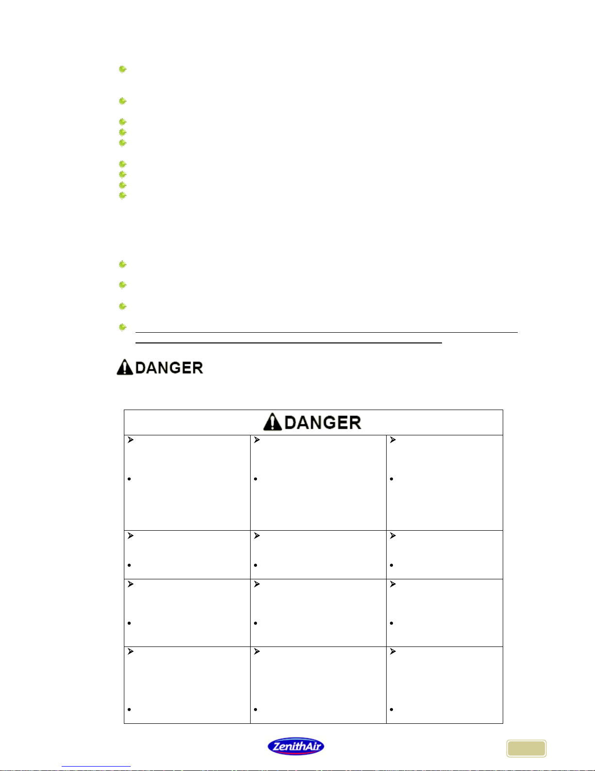
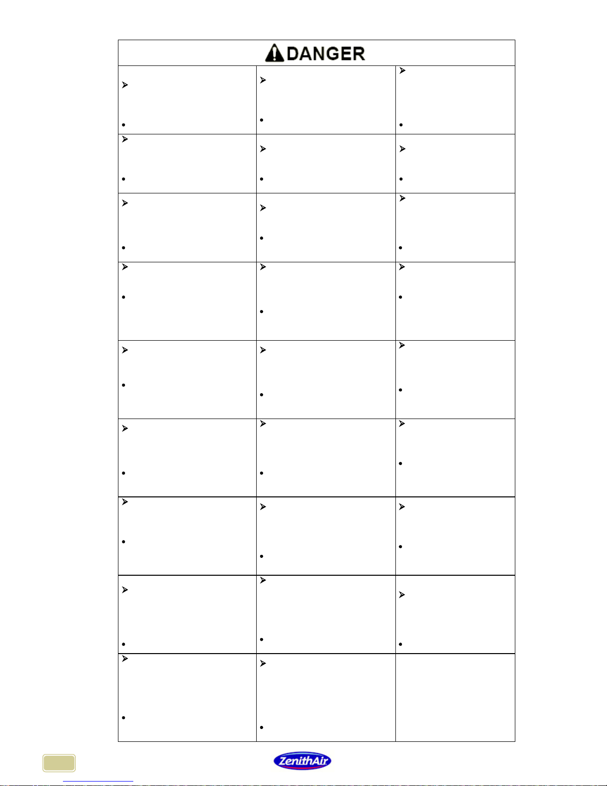
2. PRECAUTIONS
To avoid actual bodily harm or injury to users or other persons, you must adhere to the
following instructions.
To prevent injuries caused to users or to others as well as material damages, the following
instructions must be followed.
Any incorrect operation carried out following failure to read these instructions may lead to
serious physical injury and material damage.
If you do not follow these instructions, you risk using the appliance incorrectly which may lead
to actual bodily harm or damages, the severity of which are indicated below.
This symbol indicates danger of death, the risk of bodily harm and material damages.
The following tables summarise the main precautions to be taken in terms of use to avoid the
most serious risks to persons, the product and its environment
Connect to an electrical
power supply and ensure that
the appliance is plugged into
the socket correctly.
Do not switch the unit on or off
by plugging in or unplugging the
socket.
Do not use damaged or
non-
recommended cable or
sockets.
Failure to do so can cause
electric shocks or fire due to
excessive temperature.
This can cause electric shocks or
fire due to excessive temperature
elevation and short-circuiting.
This can cause electric
shocks or fire.
If the cord or the plug are
damaged in any way, have
them replaced by an
approved technician.
Do
not alter the length of the
power cable or connect it to
other electrical appliances.
Do not touch the apparatus
with wet hands or use in a damp
environment.
Do not direct the airflow
directly onto occupants.
This can cause electric shocks
or fire due to overheating.
This can cause electric shocks.
This can damage their
health.
Always ensure that the
appliance has been earthed
correctly.
Do not allow water to infiltrate
the electrical components.
Always install a suitable
electrical protection
and a
separate power circuit.
The absence of earthing can
cause electric shocks.
This can cause damage to the
machine and may cause electric
shocks.
If this is missing, there may
be a risk of fire and electric
shocks.
Disconnect the power
supply if
unusual sounds are
heard or if smoke or strong
odours begin to emanate from
the product.
Do not use the electric plug if
damaged or wrongly connected.
Do not open the unit
whilst operating.
Always ensure that the unit
is switched off and arm the
electrical protection.
Failure to do so can cause
electric shocks or fire.
This can cause electric shocks or
fire.
Risk of bodily harm.
5
Keep firearms well away from
the appliance.
Do not place the power cable
near to any apparatus that
produces heat.
Do not use the power
cable near to inflammable
gas or combustibles, such
as diesel, benzene,
solvents, etc.
Risk of fire.
This can cause electric shocks or
fire.
Risk of explosion and fire.
Ventilate the premises
thoroughly before using the air
conditioner in the event of any
gas leaks from other appliances.
Do not dismantle or modify the
unit.
Do block the flow of air
around the product.
Failure to do so may cause an
explosion, fire or burns.
This may cause damage and
electric shocks.
This may lead to
breakdowns
When the dust filter needs to
be removed, do not touch the
metal parts of the unit.
Do not clean the unit with
water.
Ensure that the room is
well ventilated if a gas
cooker is being used at the
same time.
Risk of injury.
Water may infiltrate the unit and
cause damage to the insulation.
Risk of electric shocks.
A lack of oxygen may result.
When the unit needs cleaning,
switch it off and switch on the
circuit breaker.
Do not place animals or plants
directly in front of / under
airflow.
Do not use the product for
any other purpose than
comfort air conditioning.
Do not clean the unit when it is
switched on as this may cause a
fire, electric shocks or personal
injury.
This may cause injury to animals
and may damage plants
Do not use the air
conditioner for example to
cool precision machines,
food, animals, plants, or art as
this may damage them.
Do not leave windows open
while the product is switched
on.
Hold the power cable by the
plug when you are unplugging
the appliance
Switch off and unplug the
air conditioning unit when it
is not used for a long
period.
Using the appliance with the
windows open may lead to the
appearance of condensation and
damage surrounding furnishings.
A faulty plug may lead to electric
shocks and bodily harm.
Failure to do so may cause
the unit to break down or may
cause a fire.
Do not place any obstacles
around the air inlet or in front of
the air outlet.
Ensure that the outdoor unit
support does not become
deteriorated due to severe
weather.
The dust filters must
always be installed
correctly and cleaned at
least once every two weeks.
This can cause damage to the
appliance or may cause accidents.
If the support is damaged or
deteriorated, the unit may fall.
Using the appliance without
filters or inadequate
maintenance of the filters can
lead to breakdowns.
Do not use strong detergents
or solvents to clean the
appliance.
Use a soft cloth.
Do not place heavy objects on
the electric cable, ensure that it
is not compressed in any way.
Do not drink the
condensation water given
off by the unit.
Failure to do so may result in
changes or deterioration in the
appearance, colour or surface of
the product.
Risk of overheating and fire.
It can contain bacteria that
may make you ill.
When cleaning the product,
pay careful attention to certain
sharp edges that may cause
injury.
If water should enter the indoor
unit, stop the unit immediately
and switch off the circuit
breaker.
Contact a qualified technician.
Do not leave the product
switched on during a storm,
a gale or a hurricane.
Risk of bodily harm.
Risk of short circuit or
electrocution
Risk of deterioration and fire.
If you remove any element
from the appliance, ensure that
it cannot be swallowed by
accident by a child. Place the
element out of the reach of
children.
When cleaning PLASMA
(electrostatic) type filters, open
the front panel and wait 10
minutes before touching the
filter.
If a child should swallow an
element, consult a doctor
immediately.
Risk of electric shock.
6
3. COMMAND
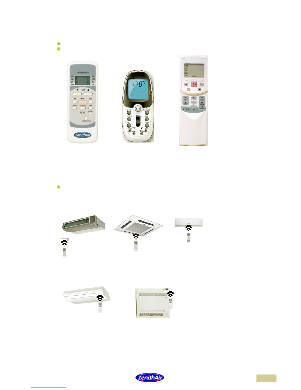
3.1 Infrared remote control
Each indoor unit is delivered with an infrared remote control.
The different types of remote control that can be supplied with the products are shown below
Type: R51 Type: R06 Type: R05
3.2 Display PCB
3.2.1 Location of the display PCB
A receiver located on a display panel on the front of the indoor unit (products of the wall,
floor/ceiling, cassette and console type) or on the front of a separate control box (DUCT type
product) receives the remote control infrared signal.
Duct Cassette Wall split
product product product
Ceiling floor Console
Product product
7
3.2.2 Model of display PCB by product
Cassette KSI18 & duct models
The infrared receptor is located on the display panel on the front of the indoor unit
(cassette model) or on the front of the display control box (DUCT model).
I = Infrared receptor
Wall split models SHI - SHR - SHF – SHI - IMHI
The infrared receptor is located on the display panel on the front of the indoor unit
Wall split models SPI – SCI – SCR – SCF –SQI – SQR– KSI – KSR
The infrared receptor is located on the display panel on the front of the indoor unit
Console model ICMI – CSI
The infrared receptor is located on the display panel on the right front of the indoor unit
8
Floor / ceiling model ASR – ASF
The infrared receptor is located on the display panel on the front of the indoor unit
A = Infrared receptor
PRECAUTIONS
Ensure that no obstacles can obstruct the infrared transmission between the remote control
and the receiver.
Do not use liquid detergent to clean the remote control.
Keep the remote control away from excessive temperatures or radiation zones.
Ensure that no remote control for any other appliance can interfere with the product.
REMOTE CONTROL SPECIFICATIONS
Voltage 3.0V
Range 8m
Temperature for use: -5°C to +60°C
FUNCTIONS
Operating modes: Cooling, heating, dehumidifying, fan, automatic.
24 hour programming.
Recommended temperature for use: +17°C to +30°C.
LCD display for all functions

9
3.3 Description of buttons on the remote control
Type : R51M/E Type : R06 Type: R05/BGE
1 TEMP
This reduces the set temperature.
2 TEMP
This increases the set temperature.
3 MODE
This enables the operating mode to be selected.
Each time the button is pressed, the operational mode changes, in the following order:
AUTO (automatic) -> COOL (cooling) -> DRY (dehumidifying) -> HEAT (heating) -> FAN (fan only)
-> return to AUTO (automatic) -> etc.
Note: the HEAT mode (heating) is only available on reversible products.
4 SWING (Wall product - cassette product – floor/ceiling product)
This enables the user to select an automatic sweeping motion or to fix the position of the air outlet
around the initial position by using the AIR DIRECTION button (see below).
5 CLEAN AIR
This function allows the ION/PLASMA filters operating and purifying the atmosphere against
pollen and impurities.
7 FOLLOW ME (IMMI model only)
This function allows selecting of the sensor which will regulate the premises. Press the button to
choose between the air return sensor inside the indoor unit (preset configuration) or the
temperature sensor built-in the IR remote controller for the temperature regulation control.
8 RESET
Resets the remote control settings (returns to the settings displayed when initially switched on).
9 ON/OFF
This starts or stops the product.
3
9
8
14
22
4
17
4’
12
21
13
11
20
1
2
1
0
6
6
1/2
3
10
4
11
17
7
14
8
12
9
20
16
19
18

10
10 FAN SPEED
This allows the user to select the fan speed of the indoor unit in the following order: automatic
speed -> LOW (low speed) -> MED (medium speed) -> HIGH (high speed) -> back to automatic
speed-> Etc.
In automatic speed mode, the product adjusts its own speed depending on the difference
between the set temperature and the temperature in the room.
11 TIMER ON
This allows the user to programme a duration after which time the product starts.
12 SLEEP OU ECONOMIC RUNNING (ECO)
Enables the user to select the energy saving mode.
In this operational mode, the length of the operating time for the compressor is limited by an
automatic and gradual increase (in cooling mode) or decrease (in heating mode) of the set
temperature: 1°C after one hour of operation, 2°C after 2 hours of operation and maintained at 2°C
thereafter.
After 7 hours of operation in energy economy mode, the product stops.
13 TIMER OFF
This allows the user to programme a duration after which time the product stops.
14 LOCK
This locks the remote control settings. Pressing this button a second time deletes this function.
15 TURBO (Wall-mounted product) / POWERFUL (Console product)
This allows the room temperature to be reached more quickly in cooling mode (high-speed fan
mode).
16 LED DISPLAY (Wall-mounted product)
This allows the set temperature display to be hidden or displayed on the display panel.
17 AIR DIRECTION (Wall product - cassette product – floor/ceiling product)
This fixes the initial position of the vents for the automatic sweeping motion.
Wall-mounted product: this allows the air blow outlet position to be reversed: upwards or
downwards.
18 SILENT (Remote controller R06)
This allows the indoor fan speed to cross in Very low speed and decrease the indoor noise level.
19 CANCEL
For cancelling the timer setting.
20 CLOCK
For setting the time displayed
21 OK (Floor/Ceiling product)
For validation of timer setting.
Note: All illustrations of this manual are with explicative character. The unit design as well as accessories and quantity can
differ according the models

11
3.4 LCD display on the remote control
Type : R51
Type : R06
1 Infrared transmission indicator
This indicator appears when the remote control transmits a signal to the receiver.
The receiver then emits a BEEP to acknowledge the signal.
2 Operating mode indicator
An index allows the user to view the operating mode selected:
AUTO = Automatic
COOL = Cooling
DRY = Dehumidifying
HEAT = Heating
FAN = Ventilation (Remote controls R05 and R11)
3 Locked indicator
The locked indicator appears when the buttons are disabled.
4 Programming indicator
The programming indicator appears in this zone:
"TIMER ON" is indicated if the product is programmed to start at a certain time.
"TIMER OFF" is indicated if the product is programmed to stop at a certain time.
"TIMER ON OFF" is indicated if the start and stop times are both programmed.
If there is no indication, then no start or stop time has been programmed.
5 Fan speed indicator
An index allows the user to view the fan speed selected:
LOW = Low speed MED = Medium speed HIGH = High speed
AUTO = Automatic speed (Remote controls R05 and R11)
If there is no indication, then the fan speed is set to automatic (Remote control R11).
6 Digital display
Deux chiffres indiquent dans cette zone la température de consigne sélectionnée.
7 Operational indicator
This icon appears when the appliance is operating.
8 Economic mode indicator
This pictogram is displayed when the unit is in running in economic mode.
9 Time indicator
4-digit display of current time.
10 Sensor indicator
This pictogram is displayed when the unit regulate by the remote controller sensor.
Type R05

12
3.5 Instructions for remote control
3.5.1 Insertion and replacement of batteries
The Infrared remote control requires two R03 type batteries.
When using for the first time, insert the two R03 batteries (provided with the product) into the
compartment in the back of the remote control by opening the sliding cover.
Respect the + and – polarity indicated on the batteries and in the battery compartment.
Close the cover after inserting the batteries.
Next, if the remote control shows that the battery power is low, repeat this process with new
batteries.
Note :
When replacing the batteries, do not use flat batteries or a different model of battery: this could cause the remote
control to malfunction.
The batteries must be removed if the remote control is not in use for several weeks: the remote control could be
damaged by any leakage of the battery chemicals.
The lifespan of a battery in normal use is approximately 6 months.
Replace the batteries if no BEEP from the indoor unit is heard or if the transmission signals on the remote control
display does not appear.
3.5.2 Preliminary operation
When the product is ready to be used, switch the main power supply switch to ON: the
"OPERATION" indicator on the indoor unit display panel will start to flash.
3.5.3 Selecting the operating mode
Automatic "AUTO" mode
Select the automatic mode (AUTO) using the MODE button.
Select the required temperature by pressing the TEMP or TEMP button.
Press the ON/OFF button, the operating indicator will appear on the remote control and the
"OPERATION" indicator on the indoor unit display panel will stop flashing:
The product automatically selects the most suitable operating mode among the operating
modes available COOL (cooling), HEAT heating, FAN (fan) and DRY (dehumidification, for
cold models only) depending on the difference between the set temperature selected and
the temperature of the air inlet measured by the indoor unit.
The fan speed is set by the product (automatic).
To stop the product, press the ON/OFF button again.
Note:
If the automatic mode is not judged to be comfortable, manually select the most appropriate operating mode (see
below).
Cooling (COOL) / heating (HEAT) / fan only (FAN) modes
These three operating modes are used for cooling (COOL), heating (HEAT) or air
circulation and filtration only (FAN).
Press the MODE button to select one of the operating modes.
Select the required temperature by pressing the TEMP button or TEMP .
Press the FAN button to select the most appropriate fan speed: automatic speed, LOW
(slow speed), MED (medium speed), HIGH (high speed).
Press the ON/OFF button, the operating indicator will appear on the remote control and the
"OPERATION" indicator on the indoor unit display panel will stop flashing: the product is
now operating in the selected mode.
To stop the product, press the ON/OFF button again.
Note
The fan only operating mode does not allow temperature regulation in the room but is used solely to circulate and
filter the air; to operate in this mode follow steps 1, 3, 4 and 5.
In other operating modes, the product regulates the room temperature using a temperature gauge located in the
indoor unit air inlet; depending on the appliance settings, the temperature in the comfort zone can in some cases
be noticeably different to the temperature displayed on the remote control.

13
Dehumidification mode (DRY)
This mode dehumidifies the air in the room.
Press the MODE button to select the dehumidification (DRY) mode.
Select the set temperature by pressing the TEMP or TEMP button.
Press the FAN button to select the most appropriate fan speed: automatic speed, LOW
(slow speed), MED (medium speed), HIGH (high speed).
Press the ON/OFF button, the operating indicator will appear on the remote control and the
"OPERATION" indicator on the indoor unit display panel will stop flashing:
The product is now operating in dehumidification mode.
The fan speed is pre-set by the product to low (LOW FAN).
To stop the product, press the ON/OFF button again.
Note
To limit the effect of the dehumidification mode on the room temperature, the product alternates the cooling
(COOL) mode with the fan only (FAN) mode.
3.5.4 Selecting fan speed
By pressing the FAN SPEED button on the remote control, the fan speed of the indoor unit
can be selected in the following order: automatic speeds -> LOW (low speed) -> MED
(medium speed) -> HIGH (high speed) -> back to automatic speed-> Etc.
For models SPI, press the “SILENCE” button to select the very low fan speed.
3.5.5 Programming ‘TIMER’ (R51M/E)
Automatic start programming function
When the product is stopped, this function enables the user to programme the time at which
the product will start up
Press the TIMER ON button once
TIMER ON appears on the remote control; the letter "h" appears next to the value 0.0
which indicates the countdown in hours and minutes before the product will start operating.
Then press the TIMER ON button several times, the length of time before starting will
increase in increments of 30 mins until 10h, then in increments of 1hour until 24h.
A half-second after depressing the TIMER ON button (once the desired length of time
before starting has been set) the remote control sends the start programme command to
the product (for remote controls R11HG/E and R05/BGE, press OK to validate the timer
setting)..
The TIMER ON message and the operating indicator remain displayed on the remote
control indicating that a start programme is active, the set temperature is once again
displayed after a few seconds and the "TIMER" programming indicator of the indoor unit
display panel is shown.
Automatic stop programming function
When the product is operating, this function enables the user to programme the time at which
the product will stop operating.
Press the TIMER OFF button once.
TIMER OFF appears on the remote control; the letter "h" appears next to the value 0.0
which indicates the countdown in hours and minutes before the product will stop operating.
Then press the TIMER OFF button several times, the length of time before stopping will
increase in increments of 30 mins until 10h, then in increments of 1hour until 24h.
A half-second after depressing the TIMER OFF button (once the desired length of time
before starting has been set) the remote control sends the start programme command to
the product (for remote controls R11HG/E and R05/BGE, press OK to validate the timer
setting).
The TIMER OFF message and the operating indicator remain displayed on the remote
control indicating that a stop programme is active, the set temperature is once again
displayed after a few seconds and the "TIMER" programming indicator of the indoor unit
display panel is shown.

14
3.5.6 Programming ‘TIMER’ (R06-R05)
Clock setting
Before programming the TIMER ON and TIMER OFF, you need to set the remote controller
clock.
Press the CLOCK button for 4 seconds.
The Hour displays under CLOCK blinking on the remote controller.
Press the button to increase, or button to decrease, the clock from minutes till minutes
(1 pressing = 1 minute).
An extend pressing on the button or allows to increase or decrease the value by step
of 10 minutes.
5 seconds after depressing the button (once the desired clock has been set) the remote
controller registers the CLOCK and displays it.
Automatic start programming function
When the product is stopped, this function enables the user to programme the time at which
the product will start up
With the appliance operating, and outside the receiver range, press the ON/OFF button
twice to delete all previous programmes.
Press the TIMER button once
appears on the remote controller; the hour "6:00" blinks near the pictogram.
Then press the button several times to increase, or to decrease the hour before
starting (1 pressing = 10 minutes)
2 seconds after depressing a button (once the desired hour before starting has been set)
the remote controller sends the start programme command to the products.
The message and the hour remain displayed on the remote control indicating that a start
programme is active, "TIMER" programming indicator of the indoor unit display panel is
shown.
Note
The TIMER function is only active once: once the programming function has been carried out, the product returns
to the previously programmed operating mode and the "TIMER" indicator on the indoor unit display panel
disappears.
Automatic stop programming function
When the product is operating, this function enables the user to programme the time at which
product will stop operating.
With the appliance operating, and outside the receiver range, press the ON/OFF button
twice to delete all previous programmes.
Press the TIMER button twice.
appears on the remote controller; the hour "0:00" blinks near the pictogram.
Then press the button several times to increase, or to decrease the hour before
starting (1 pressing = 10 minutes)
2 seconds after depressing a button (once the desired hour before stopping has been set)
the remote controller sends the start programme command to the products.
The message and the hour remain displayed on the remote control indicating that a stop
programme is active, "TIMER" programming indicator of the indoor unit display panel is
shown.
Note
The TIMER function is only active once: once the programming function has been carried out, the product returns
to the previously programmed operating mode and the "TIMER" indicator on the indoor unit display panel
disappears.

15
3.5.7 Override (MANUAL / AUTO COOL)
If the remote control is out of order or lost, the user can operate the product manually by using
the override button:
On ducted, cassette, floor/ceiling or console products, this button is located on the indoor
unit display panel (m-F-3); it is labelled "MANUAL” :
On wall-mounted products, it is located on the electrical connection box, it is accessed by
lifting up the front panel, and it is labelled "AUTO COOL” :
Using the override button:
Press once: the product will start in automatic (AUTO) mode, the operational indicator
"OPERATION" will be displayed; the remote control can now be used.
Press a second time: the product starts in cooling (COOL) mode and high speed fan
mode, the operational indicator "OPERATION" flashes, the remote control cannot be
used. After 30 minutes of operating in cooling mode, the product switches to automatic
"AUTO" mode.
Press a third time: the product stops, the operational indicator "OPERATION" is
switched off, the remote control can now be used.

16
4. DISPLAY
4.1 Display of PCB
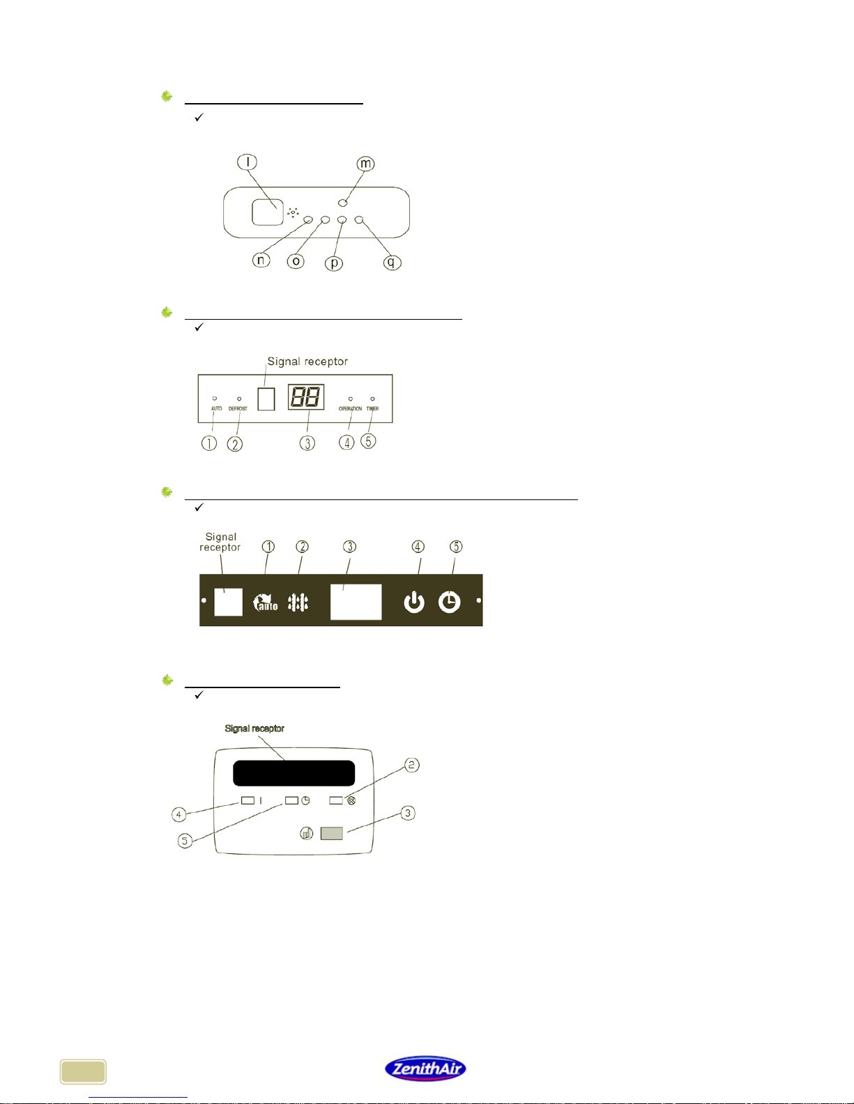
4.1.1 On model cassette18K, duct
4.1.2 On model Cassette KSI – KSF/R, Wall split SCI – SCF/R – SQR – SQI
1 = Automatic operating mode indicator "AUTO"
2 = Hot start or "DEFROST" indicator (heating mode)
3 = Set temperature display (and default temperature on some models)
4 = Operational indicator "OPERATION"
5 = Programming indicator "TIMER"
6 = ECON indicator (economic mode)
4.1.3 On model console double flux ICMI-CSI
1 = Automatic operating mode indicator "AUTO"
2 = Hot start or "DEFROST" indicator (heating mode)
3 = Set temperature display (and default temperature on some models)
4 = Operational indicator "OPERATION"
5 = Programming indicator "TIMER"
4.1.4 Sur modèles mural SHR – SHI - IMHI
1 = Automatic operating mode indicator "AUTO"
2 = Hot start or "DEFROST" indicator (heating mode)
3 = Set temperature display (and default temperature on some models)
4 = Operational indicator "OPERATION"
5 = Programming indicator "TIMER"
6 = ECON indicator (economic mode)
I = Receiver
M = Manual operation button (override)
N = Operational indicator "OPERATION"
O = Programming indicator "TIMER"
p = Hot start or "PRE-DEF" indicator (heating mode)
q = Operating fault indicator "ALARM"

17
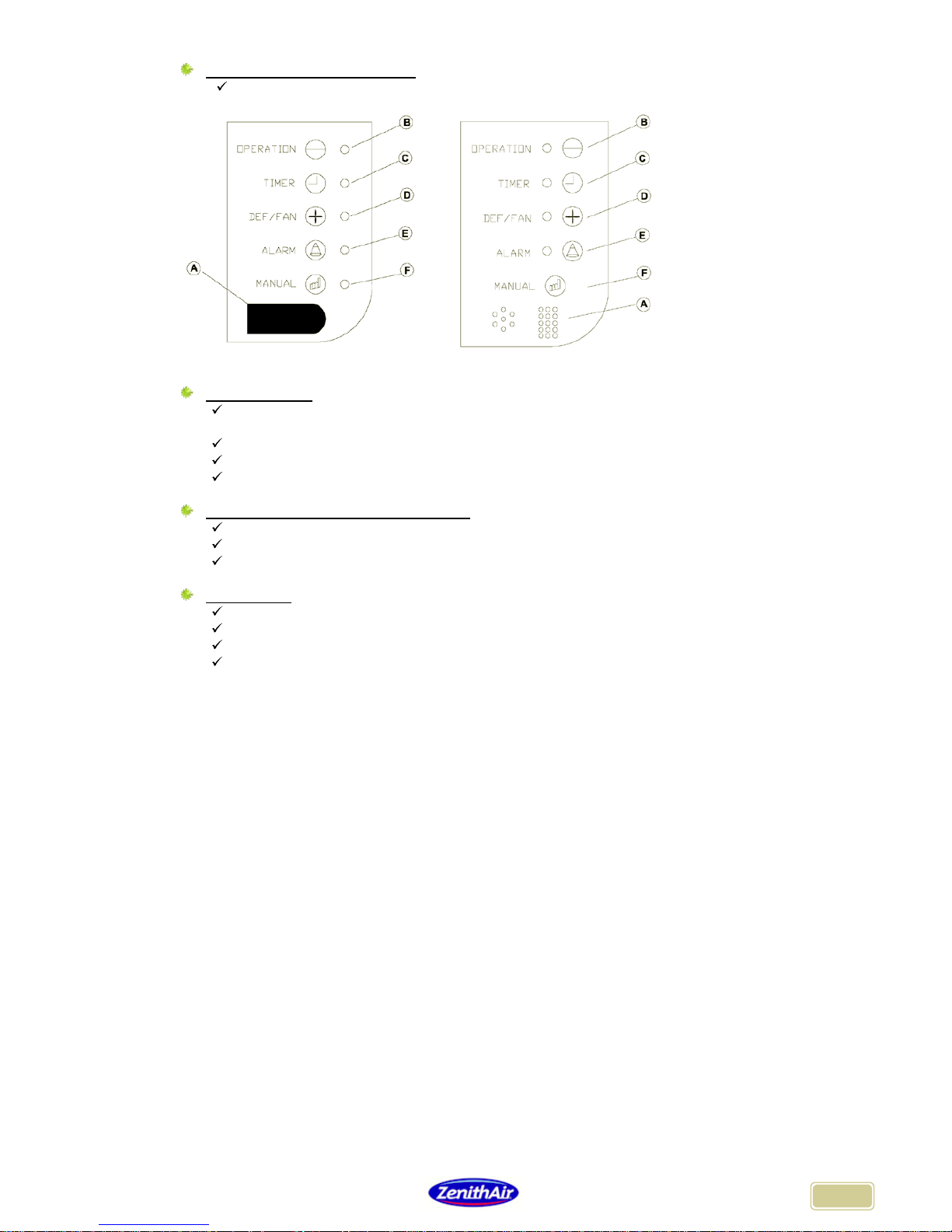
4.1.5 On models ASR – ASI – ASF
ASR18A / 24A ASR36A / 48A / 60A
ASI18A / 24A ASI36A / 48A / 60A
A - k = Infrared receiver
B - l = “OPERATION“ Operating status indicator
C - m = “TIMER” Timer setting indicator
D - j = Indicator for warm start-up or defrosting “DEFROST” (heating mode)
E - n = Indicator for unit safety mode (see self-diagnosis)
F - o = Indicator + Manual start up button (override)
5. INSTRUCTION FOR USE
5.1 General instructions
To obtain the best performances in terms of comfort and regulation, the following points should be
taken into account:
Orient the air flows correctly so that they do not blow directly onto people.
Adjust the set temperature so that it is not too excessive and so that the difference
between the inside and the outside temperature is not too large (it is recommenced that
this difference does not exceed 8°C).
Close all doors and windows in order to maintain energy efficiency and avoid severe
condensation (in cooling (COOL) mode or dehumidify (DRY) mode).
During the summer months, if possible close shutters on windows to avoid direct sunlight in
the room.
Do not install objects that may obstruct the air inlet or outlets of the indoor and outdoor
units, performance could decrease considerably and the appliance could become a safety
hazard.
Clean the filters periodically otherwise efficiency may be affected.
Before long periods during which the product will not be in use, operate the product in fan
only mode for half a day to dry the internal parts then disconnect the power supply and
remove the batteries from the remote control.
When re-starting the product after a long interval, re-connect the main power supply and
wait for half a day before operating the product.
For information :
The compressor will only re-start 3 minutes after a power cut or a regulation stop (antishort protection cycle).
Following a power cut, the product will re-start in the operating mode it was set to before
the power cut occurred.
In heating mode, the indoor unit fan will only begin operating when the temperature of the
heat exchanger is high enough to avoid any problems of discomfort.

18
5.2 Wall-mounted model
The automatic air outlet vents and sweeping vents must be carefully positioned :
A mechanical vent enables the airflow to be directed downwards.
This vent is controlled by the remote control (see above).
Note :
Do not attempt to move the indoor unit mechanical vent manually.
Do not operate the indoor unit with the mechanical vent in the closed or almost closed
position (loss of efficiency or risk of safety hazard).
It is not possible to command the mechanical vent when the product is stopped (OFF).
Manual deflectors enable the airflow to be directed to the left or the right.
Use the lever to position the manual vents, taking care not to touch the fan blades or the
horizontal mechanical vent, and also not to damage the manual vents.
5.3 Cassette model
The automatic air outlet vents and sweeping vents must be carefully positioned:
A mechanical vent enables the airflow to be directed downwards.
This vent is controlled by the remote control (see above).
Note :
Do not attempt to move the indoor unit mechanical vent manually.
Do not operate the indoor unit with the mechanical vent in the closed or almost closed
position (loss of efficiency or risk of safety hazard).
It is not possible to command the mechanical vent when the product is stopped (OFF.
5.4 Duct model
In the event that protective grilles (not provided) are installed over the indoor air outlets, they must
be equipped with deflection vents that should ideally be positioned downwards in heating mode
and upwards in cooling mode.
Cooling Mode Heating Mode

19
5.5 Ceiling floor model
The angle of air blower vents and automatic sweep must be selected carefully:
A motorised vent makes it possible to direct the air flow from top to bottom.
This vent is controlled with the remote control (see above).
Automatic sweep Cooling mode heating mode
On the ASR models, the automatic sweep function is also available for horizontal sweep (see
remote control R05)
For the other models, manual vents can be used to direct the air flow left or right.
Note
Do not move motorised vents manually on the indoor unit.
Do not operate the indoor unit with the motorised vent in closed position or only slightly open
(loss of performance or risk of switching to safety mode).
When the product is switched off (OFF), the motorised vent cannot be moved.
Use the lever to direct the manual vents, being careful not to touch the turbine or the
horizontal motorised vent and not to damage the manual vents.
5.6 Console model
It is possible, according to the shape of this switch, to make blow the product by the top only or by
the bottom and the top.
Switch of
selection

20
6. MAINTENANCE
IMPORTANT: before cleaning the indoor unit, ensure that the product is switched off.
Use a dry, clean cloth to clean the plastic parts of the indoor unit and the infrared remote control.
A lightly dampened cloth can be used to clean the indoor unit if it is very dirty.
Do not use a damp cloth to clean the remote control.
Do not use anti-dust products as these may affect the plastic parts.
Do not use solvents, petrol or any other petrol derivative or corrosive chemical products or any
products containing polishing powders
6.1 Dismounting and cleaning the filter :
6.1.1 Wall mounted model
Lift up the Unclip the filters Remove
front panel from their fixings the filters
6.1.2 Cassette model
Dismantling the front panel and the filter following diagrams A and B :
Open the front grille by pushing in the 2 tabs as shown in diagram A.
Disconnect the electric cable from the holding panel
Dismantle the front grille as shown in diagram B.
6.1.3 Duct model
In the case of assembly with air inlet grille (option) :
Open the front grille by pushing in the 2 clips as shown.
Disconnect the electric cable from the holding panel
Dismantle the front grille as shown.

21
6.1.4 Ceiling floor models
Dismantle the front panel and the filter following diagram A
Open the return grid by pulling it towards you on each side
Pull filters upwards to remove.
On some models, filters can be removed without dismantling the front panel
6.1.5 Console models
6.2 Cleaning the filters
Clean the filters with a vacuum cleaner (fig. 1) or with tepid soapy water (fig. 2).
Rinse filters with clear water and dry them in a temperate ambience (do not dry in the sun or
near a fire).
Replace filters by following the dismantling instructions in reverse.
Ensure that the filters are repositioned as prior to dismantling; for the PLASMA filter, make sure
that each end is fully engaged in its housing to prevent deficient electrical contact.

22
7. DIAGNOSIS
WARNING
If one of the following phenomena occurs, stop the product immediately (OFF), unplug the electric
cable immediately (circuit-breaker) and contact the nearest approved technician.
The operating indicator
"OPERATION" or other indicator on the display panel is flashing rapidly (5 times per second)
and this flashing persists even when the power is switched off and on again and the product has been left to operate
for more than 3 minutes after carrying out this action.
The fuses or the circuit breaker frequently trip.
Foreign matter or water has entered the product.
The remote control does not work or is functioning incorrectly.
Smoke, flames or a burning odour is emanating from the product.
If you encounter any of the following operational problems, you will save time and money if you check
the points indicated in the table before contacting a repair technician.
PROBLEM
CAUSES
EXPLANATION / ACTION
The fan speed can no longer be
adjusted with the remote control.
Check that the appliance is not in
AUTO or DRY mode.
In these 2 modes, the product
selects its own fan speed.
The infrared transmission
indicator is no longer appearing on
the remote control.
Check whether the remote control
batteries
are inserted and that they are
not flat.
Insert batteries in the remote control
or change them.
The set temperature is no longer
appearing on the remote control.
Check whether the remote control
batteries are inserted and that they are
not flat.
Check whether the remote control is
programmed to be in fan only mode.
Insert batteries in the remote control
or change them.
In fan only mode, the set
temperature is not displayed.
The TIMER ON, TIMER OFF or
TIMER ON OFF indicator
disappears from t
he remote control
display after a certain time has
elapsed.
Check whether the programmed
duration has elapsed.
Once the programmed duration has
elapsed, the indication disappears
from the remote control.
There is no BEEP sound from the
receiver to i
ndicate that a signal is
received when the ON/OFF button
is pressed.
Ensure that the remote control
batteries are not flat.
Ensure that the remote control emitter
is correctly positioned towards the
receiver and that there are no
obstructions between them.
Change the remote control batteries
if necessary.
Position the remote control correctly
towards the receiver and press
ON/OFF again.
None of the remote control
buttons are working.
The remote control processor is
blocked.
Press the reset button on the remote
control.
The product is not starting.
There is no electric current in the
building.
The product has been disconnected.
The fuses have blown.
The remote control batteries are flat.
The TIMER ON programming function
is selecte
d and is preventing the product
from working.
Wait for the electricity supply to be
reconnected in the building.
Reconnect the product to the
electricity supply.
Replace the fuses.
Replace the remote control batteries.
Wait for the TIMER ON programme
to end or cancel the TIMER
programme.
The product is not supplying
enough heat or cold even though
the indoor unit fan is working.
The set temperature is not suitable.
The mechanical air outlet vents are
almost closed.
The dust filters are clogged.
Doors or windows are open.
The air inlets of the indoor or outdoor
units are obstructed.
The compressor time delay
mechanism (3 minutes) is in process.
Select a more suitable set
temperature.
Re-
position the mechanical vent
using the remote control.
Clean the dust filters.
Close doors or windows.
Clear the unit's air inlets before
restarting the product.
Wait until the compressor time delay
has finished.
The indoor unit is not working in
cooling or dehumidifying mode (but
is working in heating mode).
If the product is a multisplit type
product and if one of the indoor units is
set to heating mode, none of the other
indoor units can function in cooling or
dehumidification modes.
Set all the multisplit indoor units to
either c
ooling, dehumidification, or to
stop.

23
Information provided in this documentation can be modified without prior notice.
Information that was not available when
this documentation went to press may be integrated later.
The most recent updates can be consulted on www.zhendre.com

24
122, avenue des Pyrénées – BP82 – 33883 Villenave d’Ornon Cedex – France
WEB : www.zhendre.com
 Loading...