

Page 1
Installation Instructions
for the
~Nnw
data
systems
DOUBLE-DENSITY DISK CONTROLLER
Model Z-89-37
Copyright © 1981
ZENITH DATA SYSTEMS
All Rights Reserved
Printed in the United Stales of America
ZENITH DATA SYSTEMS
SAINT JOSEPH, MICHIGAN 49085
595-2707-01
Page 2

Page 2
INTRODUCTION
The
Z-89-37 Double-Density Disk Controller inter-
the
Z-89
faces
troller
soft-sectored disks.
Double-Sided (H-17-4 drives):
Single-Sided (H-17-1 drives):
will
96 tracks
80 tracks
Single
48 tracks
40 tracks
Single
Computer
read
and
per
per
or
double
per
or
double
with
floppy
write
as follows to
inch
side
(160 tracks total)
density
inch
density
disks.*
drives
The
Con-
using
Required software is:
HDOS
CP/M
NOTE:
shown
Backplate Modification Kit before
product.
version
or
version
If
your
below,
2.0
(updated
2.2.03 (or higher)
Computer
then
you
has
must
or higher)
a backplate
also install
you
like
the
the
install
one
H-88-6
this
0 0
0
*cassette operation is not supported.
0\
0\
]0
0
]
IBACKPLATE I
,----'.----r--
I I
I
I
L
____
I
I
J
0
HOLE
MAY
MAY
NOT
PRESENT
OR
BE
Page 3
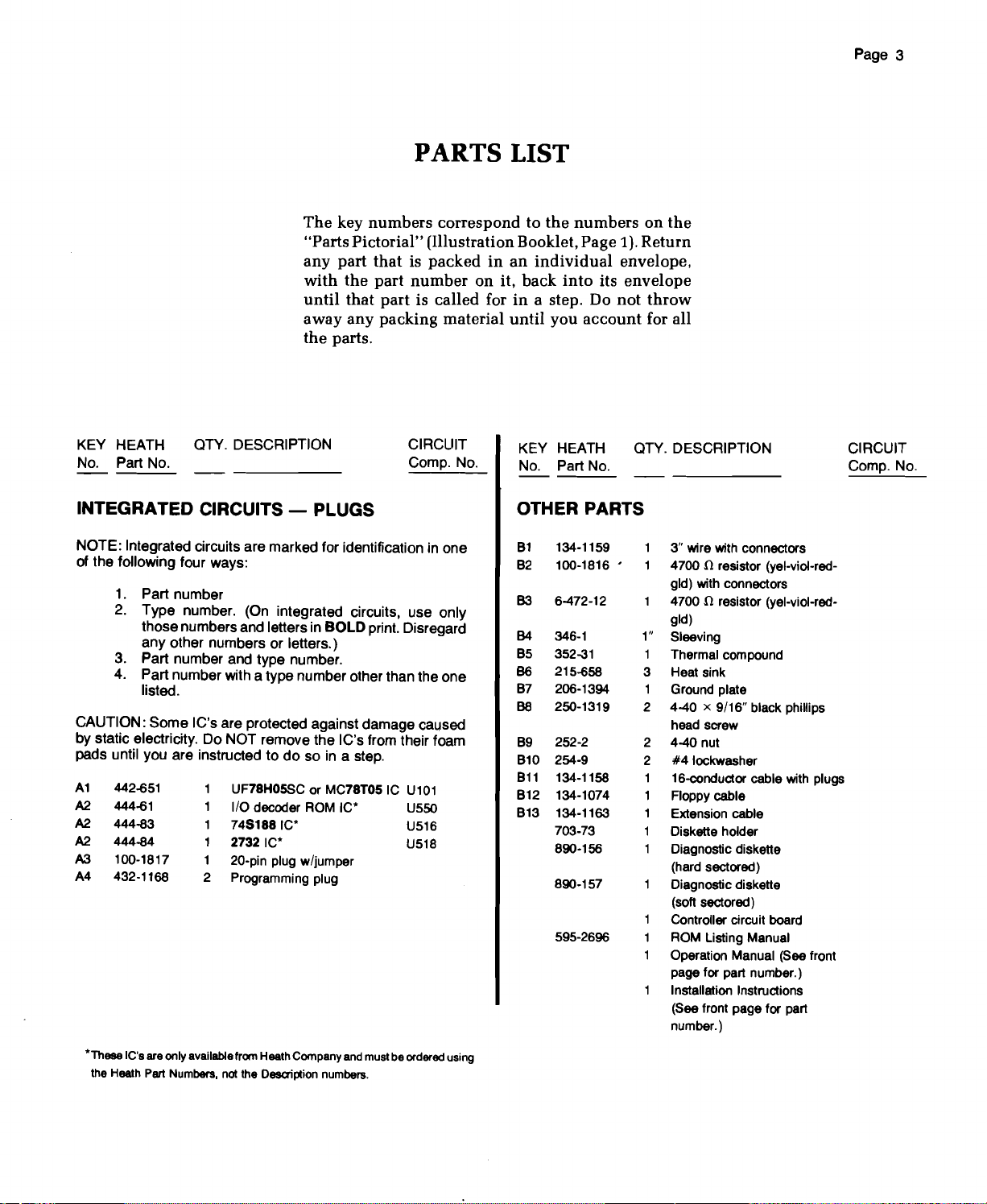
PARTS LIST
The
key
numbers
"Parts Pictorial" (Illustration Booklet, Page 1). Return
any
part
that
with
the
part
until
that
part
away
any
packing material
the
parts.
correspond to
is
packed
number
in an
on it,
the
numbers
individual
back
into
is called for in a step. Do
until
you
account
envelope,
its
envelope
not
on
the
throw
for all
Page 3
KEY HEATH OTY. DESCRIPTION
No. Part No.
CIRCUIT
Compo
No.
INTEGRATED CIRCUITS - PLUGS
NOTE: Integrated circuits are marked for identification in one
of the following four ways:
1. Part number
2. Type number. (On integrated circuits, use only
those numbersand lettersin
any other numbers or letters.)
3. Part number and type number.
4. Part number with a type number other than the one
listed.
CAUTION: Some IC's are protected against damage caused
by static electricity. Do NOT remove the IC's from their foam
pads until you are instructed to do so in a step.
A1
A2
A2
A2
A3
A4
442-651
444-61
444-83
444-84
100-1817
432-1168
1
UF78HOSSC or MC78TOSIC U101
1
1/0 decoder ROM
1
74S1881C'
1
27321C'
1
20-pin plug w/jumper
2
Programming plug
BOLD print. Disregard
IC'
U550
U516
U518
KEY HEATH OTY. DESCRIPTION
No. Part No.
OTHER PARTS
81 134-1159
100-1816 '
82
B3 6-472-12
B4
346-1
85
352-31
B6 215-658
87 206-1394
250-1319
B8
252-2
89
810 254-9
811 134-1158
812
134-1074
813
134-1163
703-73
890-156
890·157
595-2696
3" wire with connectors
n resistor (yel-viol-red-
4700
gld) with connectors
n resistor (yel-viol-red-
4700
gld)
1"
Sleeving
1
Thermal compound
3
Heat sink
1
Ground plate
2
2 4-40 nut
2
1
1
1
1
1
9/16"
4-40 x
head screw
#4
lockwasher
16-conductor cable with plugs
Floppy cable
Extension cable
Diskette holder
Diagnostic diskette
(hard sectored)
Diagnostic diskette
(soft sectored)
Controller circuit board
ROM Listing Manual
Operation Manual (See front
page for part number.)
Installation Instructions
(See front page for part
number.)
black phillips
CIRCUIT
Compo
No.
'TheseIC's are only available fromHeath Company and must be ordered using
the Heath Part Numbers, not the Description numbers.
Page 4
Page 4
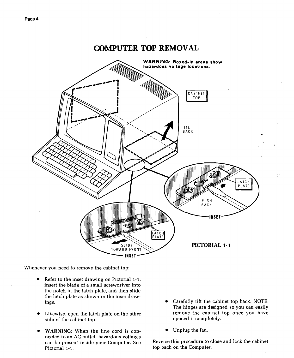
COMPUTER TOP REMOVAL
~
WARNING:
hazardous
---~~
.->:
I I •
._ I
'--~
i
I
I
~
Boxed-In
voltage
BACK
areas
locations.
TILT
show
PUSH
BACK
Whenever
• Refer to
• Likewise,
•
you
need
the
insert
the
blade
the
notch
in
the
latch
plate
ings.
open
side
of
the
WARNING:
nected
can
Pictorial
to an AC outlet,
be
present
1-1.
~
to
remove
inset
drawing
of a
small
the
latch
as
shown
the
latch
cabinet top.
When
the
inside
the
cabinet top:
on Pictorial
screwdriver
plate,
and
in
the
plate
line
hazardous
your
Computer. See
Sli
TOWARD
then
inset
on
the
cord
voltages
DE
FRONT
INSET
1-1,
into
slide
draw-
other
is con-
• Carefully tilt
The
remove
opened
Unplug
•
Reverse
top back on
this
PICTORIAL 1-1
the
hinges
procedure
the
are
the
cabinet
it completely.
the
fan.
Computer.
cabinet
designed
to close
top
back. NOTE:
so you can easily
top
once
you
and
lock
the
have
cabinet
Page 5
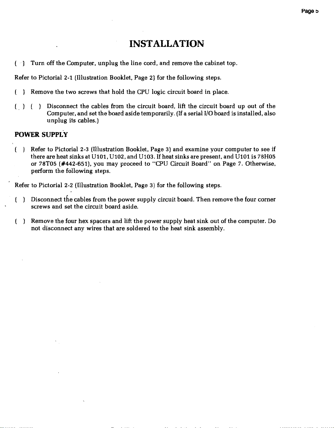
INSTALLATION
()
Turn
off
the
Computer,
Refer to Pictorial 2-1 (Illustration Booklet, Page 2) for
the
( ) Remove
(~)
( ) Disconnect
Computer,
unplug
two screws
and
its cables.)
the
cables from
set
unplug
that
hold
the
board
the
line
cord,
and
the
CPU logic circuit board
the
circuit board, lift
aside
temporarily.
remove
the
the
cabinet top.
following steps.
in
place.
the
circuit board up out of
(If
a serial I/O board is installed, also
the
Page
e
POWER
( ) Refer to Pictorial 2-3 (Illustration Booklet, Page 3)
Refer to Pictorial 2-2 (Illustration Booklet, Page
( ) Disconnect
( ) Remove
SUPPLY
there are heat sinks at
or 78T05 (#442-651),
the
perform
screws
not
disconnect any wires
following steps.
the
cables from
and
set
the
the
four
hex
circuit board aside.
Ul0l,
Ul02,
and
Ul03. Ifheat sinks are present,
you
may proceed to "CPU Circuit Board" on Page 7. Otherwise,
3) for
the
the
spacers
that
power
and
are soldered to
lift
supply
the
power
circuit board.
supply
the
and
examine
following steps.
heat
heat sink assembly.
Then
sink
your
remove
out
of
computer
and
Ul0l
the
four corner
the
computer. Do
to see if
is 78H05
Page 6

Page 6
•
REGULATOR
HEATSINK
Refer to Pictorial 2-3 (Illustration Booklet,
De'tail 2-3A for
( ) Remove
UI01.
the
WARNING: You
thermal
this
discomfort if it gets
rinse
gets on
cleaning,
compound
traces of CO
( ) Locate
( )
compound
compound
your
your
small
Spread a small
onto
circuit
the
the
following steps.
the
two
screws
Then
remove
screws
so
compound.
aside.
will
in
is
not
eyes
with
clothing,
handle
contains
,
2
the
thermal
slit
in
one
the
UA78H05SC or MC78T05
(#442-651).
and
be
using
the
following steps.
caustic, it
into
your
warm
the
zinc
amount
water.
it
may
compound
oxides,
compound
side.
Squeeze
that
discard
Dow
may
cause
eyes.
If
require
Si02 and
of
thermal
the
hold
the
Corning
If
this
the
carefully.
pod
pod
Detail 2-3A
Page
3)
and
IC socket
IC,
and
set
340
Although
temporary
happens,
compound
professional
This
slight
and
make
a
compound
integrated
to
remove
( )
Spread a small
on
UI0l:
( )
space
the
socket is
in
the
you
NOTE:
UI02
tion."
these
( )
( )
If
and
If
locations,
Remount
ulator
fore.
Remount
ulator
fore.
amount
the
back of
Refer to Detail 2-3A
of
regulator
heat
removed
your
UI03,
your
heat
heat
the
the
Ie.
Install
heat
properly
sink,
and
earlier.
Computer
proceed
Computer
proceed
the
IC
regulator
sink
and
the
IC
regulator
sink
and
of
regulator
the
sink
at
seated
then
already
to
"Power
does
with
thermal
thermal
in
install
not
the
thermal
heat
and
IC
in
UI01.
its
has
have
following steps.
at
UI02.
compound
at
UI03.
compound
compound
sink.
note
the
the
socket
Be
sure
mounting
the
two
heat
sinks
Supply
Installa-
heat
Use a reg-
Use
sinks
wide
and
the
holes
screws
at
at
as be-
a regas be-
Page 7

POWER SUPPLY INSTALLATION
Again
( )
( )
If
Otherwise,
( )
refer to Pictorial 2-2 for
Remount
four
Remount
the
6-32
four
6-32 x 1/4"
the
hex
the
power
spacers
power
earlier. NOTE:
installed
at A,
shown.
you
have
a voltmeter,
proceed
Connect
sink
as
shown.
the
common
to
If
your
you
"CPU
the
supply
you
removed
supply
screws
unit
must
reinstall
make
the
Circuit
voltmeter
following steps.
heat
circuit
that
had a lockwasher
following tests.
Board."
lead
sink
with
earlier.
board
you
removed
it at A as
to
the
the
with
heat
(/J
U518: Remove
2732 IC (#444-84) at U518.
has
the
16K
adapter
temporarily
programmed
a
not
(/)
U550: Remove
the
removed
(-r
Remove
be
I/O
remove
needed
decoder
part
and
will
set
U557.
If
you
(NOTE:
IC's
must
ever
be reinstalled.)
the
IC at U518.
circuit
it if necessary.)
PROM.
The
Then
(If
your
board
This
removed
install
Computer
installed,
part
further.
and
discard
the
Ie.
Then
ROM IC (#444-61) at U550.
not
be
aside
remove
needed
the
the
2-89-37,
further.
IC's at U558
then
Page 7
the
part
is
will
install
The
and
these
NOTE:
following
and
( )
( )
( )
If
you
correct
Plug
Measure
+5.5
Measure
+5.5
Measure
+13.2
Turn
cord.
do
steps,
the
in
the
TPl.
volts
TP2.
volts
TP3.
volts
off
Then
not
obtain
immediately
problem
line
cord
The
De.
The
DC.
The
De.
the
Computer
disconnect
aside.
CPU CIRCUIT BOARD
Refer to
( )
Pictorials
Reconnect
supply
circuit
2-2
and
the
four cable
board.
the
unplug
before
and
turn
voltage
voltage
voltage
and
the
2-3 for
(Also
proper
results
the
you
proceed.
on
the
should
should
should
unplug
voltmeter
the
following step.
plugs
to
see
Pictorial 2-3.)
in
the
line
cord
Computer.
be
+4.5
be
+4.5
be
+10.8
the
line
and
set it
the
power
to
to
to
IIIll
1~~~~r·1r
PI. I Pl. I POI I
".
I PI•
rc LEADS
.\
Again
/U516:
( )
refer to Pictorial 2-1 for
Refer to
and
remove
and
2-1A
U516.
This
removed
the
install
part
part
inset
drawing
IC at U516.
the
is a
programmed
will
not
the
#1
Then
745188
be
needed
following steps.
on Pictorial 2-1
refer to Detail
IC (#444-83) at
PROM,
the
further.
Detail
INDEX
MARK
2·1A
Page 8

Page 8
I BOARD I
PICTORIAL 2-5
H-88-1
fLOPPY
I/O
CIRCUIT
1
DISK
Page 9

Page 9
Refer to Pictorial 2-4 (Illustration Booklet,
the
following steps.
On
the
left
side
ofthe
CPU
( )
of four
Pictorial. Remove
will
not
two
plugs
be
changed.
( )
Plug
onto
nector
Plug
Be
sure
nected
bered
off.
The
This
NOTE:
cut
( L) U558:
U558. Be
end
properly.
( )
Plug
cable
to
position
dot
or arrow)
programming
be used).
from 0 to 1.
one
end
the
top
plug
plugs
onto
the
other
the
center
to
pin
14 of
from
top
20-pin
plug
indicates
Install
the
with
the
sure
to
indicated
connectors
the
oftheplug
plugs
and
set
Then
The
of
the
3"
near
U518. (Be
all
three
end
of
the
hole
of
the
plug.
to bottom.)
with
jumper
pin
1 of
20-pin
position
end
into
pin 1 end
into
circuit
aside
reposition
bottom
wire
wire
the
the
plug
the
of
socket
(marked
board
as
shown
the
plug
with
sure
pins
of
onto
connector
(The
plug
has
plug.
with
plug
with
the
16-conductor
U557. Be
the
pin 1 end
socket.
Page
4) for
is a
in
top
plug
the
middle
will
connectors
the
con-
the
plug.)
plug
P508.
is con-
is
num-
one
corner
jumper
the
pin
sure
with
a color
of
row
the
(it
not
at
the
Install
plug
nector
the
other
proceed
the
4700 n
P512. Be
plugs
connector
Otherwise,
( )
Proceed to "CPU Installation."
Z-89-47
For a
system
Z-89-47 I/O
and
P512. However, before
properly
resistor
Return
Company
this
modification.
tion
yourself,
1
(yellow-violet-red),
the
resistor (see
resistor
side (not
board
when
must
the
Z-89-47
or a
between
the
as
shown
to operate
board
plugged
be
added
Zenith
use
component
in
Page 5).
( ) Refer to Detail 2-6A
graming
plug
as follows:
resistor
sure
onto
pin 1 and
properly
should
into
to
circuit
Data
If
you
the
slide
the
inset
pins 1 and
the
center
plugs
be
installed
the
plugs
the
Z-89-47
board
System
want
to
4700
the
length
drawing),
12 of
side) of
with
connectors
hole
of
the
center
onto
pin
12.
with
the
Z-89-37,
at
plugs
Z-89-47
P506
will
and
circuit
(#85-2442) to
Service
make
the
n,
1/4-watt
of sleeving over
and
plug
P2 on
the
Z-89-47
one
hole
P506
operate
P512, a
board.
Heath
Center
modifica-
resistor
solder
the
circuit
Pictorial 2-6 (Illustration Booklet,
and
set
the
170/174 pro-
tv 174.
onto
con-
of
the
for
the
foil
If
you
do
NOT
circuit
board
programs
disks to
with
H-88-1
on Page 10.
double-density,
the
following
floppy
,
and
intend
in
data
disk
your
from
steps.
I/O,
to
use
system
single-density,
soft-sectored disks),
proceed
( ) Refer to Pictorial 2-5
If
you
mounting
are
going
bracket
to
use
and
the:
• Z-89-47 interface
"Z-89-47,"
• Z-89-67 interface
"Z-89-67."
the
(needed
If
you
and
the
circuit
circuit
H-88-1
do
intend
to "CPU
remove
H-88-1
board,
board,
floppy
for
disk
transferring
hard-sectored
proceed
to
use
Installation"
the
accessory
circuit
board.
proceed
proceed
I/O
the
to
to
( ) Install
P512.
Page
If
NOTE:
plugs, be
you
sure
Z-89-47
See
Pictorial 2-7 (Illustration Booklet,
6).
ever
move
to
remove
board
this
the
at
board
4700 n
plugs
to
another
resistor
P506
that
and
set
you
of
the
just installed.
Proceed to "CPU
Z-89-67
Installation."
( ) Refer to Pictorial 2-8 (Illustration Booklet, Page
and
6)
to
reposition
the
indicated
programming
positions
on
plugs
the
Z-89-67 I/O
Jl
and
J2
board.
( ) Install
Z-89-67
board
at
plugs
P506
and
the
P512. See Pictorial 2-7 (Illustration Booklet,
Page 6).
Page 10

Page 10
CPU INSTALLATION
( )
Again
reinstall
in
cables as
the
place
bottom
refer
the
CPU logic
with
shown.
right-hand
to
Pictorials
its
two
(Be
CPULOGIC
CIRCUIT
circuit
screws
sure
to
corner
BOARD
2-1
and
board.
and
reconnect
reconnect
of
the
2-9,
Secure
P513 in
board.)
and
it
the
CONTROLLER
Refer to Pictorial 2-10 for
Locate
necessary,
tion
J6.
nected
mined
cut. See Pictorials 2-13
PROGRAMMING
the
plug
positions
move
the
programming
This
plug
selects
to
plug
P3. (Drive
by
how
the
drive
following
J4
through
which
numbers
programming
and
2-14,
Booklet, Page 8). J4 = DS1, J5 = DS2, J6= DS3,
and
(-.-j
r Be
Position
are 48TPI
~
I
I
J7 = DS4
sure
, I
, '
'I
I:
~
I
"
~
I
: :
I'
. I
i!
i'
t
: i
i
~
<
!!
plugs
plug
Wanco
SERIAL
INTERFACE
CIRCUIT
BOARD
(presently
J1
and
J2 are at 170.
J3 at 1
unless
Model
not
supported).
any
of
82 drives.".
: !
I
lEI
steps.
J7
and,
plug
to posi-
drive
is con-
are
deter-
plugs
Illustration
your
drives
if
are
DCE
1340-347
PICTORIAL 2-9
*All drives connected to a single Z-89-37 should be of the same type.
If they are not, the precompensation will be wrong for at least one of
the drives. This will result in reduced data integrity and poor reliability.
Page 11

Page 11
PICTORIAL 2-10
Page 12

Page 12
CONTROLLER INSTALLATION
Refer to Pictorial 2-11 (Illustration Booklet, Page 7) for
the
following steps.
( 1 Remove
moving
this
(... ) Install
and
Plug
nectors
shown.
&('Refer to
mount
cable to
ground
head
nuts.
cable as
move
the
accessory
the
two
has
not
already
the
wired controller
P510.
the
free
end
into
IC socket P5
Then
the
inset
the
larger
the
rear
plate,
screws,
Be
sure
two
to
shown.
the
rear panel.)
mounting
screws
that
been
done).
circuit
of
the
16-wire cable
with
neatly
dra
route
wing
on Pictorial 2-11
connector
panel
at FR-1 as
two
4-40 x 9/16" black
#410ckwashers,
position
the
hold it in
the
the
cable as
of
the
marked
bracket by re-
board at P504
with
pin 1 end
extension
shown.
and
edge
(If necessary, temporarily re-
place
con-
shown.
and
Use a
phillips
two
4-40
ofthe
(if
as
( ) Route
( \) If you are using a
the
extension cable as
into
the
bottom
circuit board.
cable as
the
into
shown.
smaller
the
indicated
connector
circuit board
plug
the
free
connector
Position
drive
connector
(with
the
end
of
of
the
of
the
marked
in
your
the
marked
cable
shown
the
new
computer,
new
floppy cable
of
the
edge up)
into
and
plug
controller
edge
of
controller
your
floppy
it
the
plug
and
drive as before.
( )
Remount
its
two
the
accessory
screws.
mounting
bracket
with
DRIVE PROGRAMMING
Refer to
select
figuration Eis
the
following
the
configuration
normally
chart
and
that
fits
used
for transferring
Pictorial 2-12,
your
situation. Con-
data
and
and
programs from hard-sectored disks to soft-sectored
disks.
FLOPPY DISK
CONTROLLER BOARD(S)
A
H~8·1
H~8-1
B
C
Z~9-37
Z~9-37
D
H~8-1 & Z~9-37
E
TYPES OF DRIVES:
• 48 TPI (H-17-1)
.96
TPI (H-17-4)
48 TPI (H-17-1) only.
Internal drive present
48 TPI (H-17-1) only
Internal drive absent
Either*
Internal drive present
Either*
Intemal drive absent
Either*
Internal drive present
Drive 0
DS3 DS2
No drive installed
DS1
(Z~9-37
jumper installed at J4)
No drive installed
(Z~9-37
at J7)
DS3 [Drive 0 is
48 TPI (H-17-1)
drive connected to
H-88·1.
jumper installed at J6. ]
jumper installed
Z~9-37
Drive 1 Drive 2
DS3
DS2
DS1 DS2
DS1 (Drive 0 connected
to
Z~9-37)
DS1
DS2
DS3
DS2 (Drive connected
Z~9-37)
Page 13

DRIVE
~
DRIVE
1 2
Page 13
DRIVE
------------
PICfORIAL
After you select
Pictorial 2-13 (Illustration Booklet, Page 8) to program
any
48TPI (H-17-1) drives, or Pictorial 2-14 (Il-
lustration
(H-17-4)drives.
drives
single-density
ming
drives,
ting
replacing
dip
supplied
( )
programmed
by
physically
interchanging
the
programming
switch.
for
Again
cabinet
the
configuration
Booklet, Page 8) to
[Pictorial
controller.]
the
programming
Two
use
if you
refer to
top
and
uncut
2-15
to
be
You
interchanging
the
programming
plugs
(if
programming
need
Pictorial
reconnect
you
program
shows
used
with
can
do
preprogrammed
presently
plug
with a properly
them.
1-1
and
the
fan.
want,
refer to
any
96 TPI
48 TPI (H-17-1)
the
H-88-1,
this
program-
plugs,
uncut); or by
replace
plugs
cut-
set
are
the
~
u
2·12
Proceed to
the
• You
from
disks.
• You
tem. (See
• You
(See
• You
tem.
• Your Computer
the
Diagnostic routines.)
Operation Manual. Use
want
to transfer
hard
sectored disks to soft sectored
want
to
thoroughly
the
Diagnostic routines.)
want
to
"reconfigure"
the
"Reconfiguration"
want
to
learn
"In
Case of Difficulty" section
programs
more
about
develops
test
that
Manual
your
your
section.)
your
a problem. (See
and
disk
system.
disk
and
if:
data
sys-
sys-
the
Page 14

Page 15

Page 16

 Loading...