

Zenith Z-200 Owner's Manual

Z-200
Computers
PC
Series
Owner's
Manual
Welcome
Congratulations on your purchase
The Z-200
both personal and business needs.
With
Zenith, the future
a stand-alone tool
business automation package. Combined with Zenith Data Systems software, your personal computer can easily provide practical and affordable
solutions to many
business applications, including data processing, telecommunications, networking, and financial analysis.
This manual has been prepared
user. Welcome to personal computing at
pledge and commitment that the quality goes in before the name goes
on.
PC
represents a state-of-the-art design capable
is
here today. Your new computer can act as
or
function as the center
of
your business problems. It can satisfy a variety
of
a new Z-200
of
a powerful and expandable
for
you, the new computer owner and
its
very best, and accept Zenith's
PC
Series Computer.
of
satisfying
of

Preface
This Owner's Manual
is
intended
to
be used as a reference guide whenever
you wish to set up, add
to,
or understand more about your Z-200
PC
Series Computer System.
Chapter 1 - Unpacking and connecting your new computer system are
the first things covered in this chapter
of
the Owner's Manual. After a
description
of
how to power up the system,
all
the keys on the keyboard
are explained individually. The program for setting up the computer with
the various options installed
is
also included in this chapter.
Chapter 2 - This chapter tells how to get software running
in
your
computer from either the floppy disk drive or an optional Winchester
drive. Instructions for making backup copies
of
disks and configuring the
system for printers are also covered.
Chapter 3 -
In
the extreme case where your computer does not seem
to
work correctly, this chapter covers error messages, cover removal and
diagnostic
LEOs,
as well as information on calling for assistance.
lllapter 4 - Summaries
of
the commands used in both the MFM-200
program
and
MS-DOS Version 3 are included
in
this chapter.
Chapter 5 - Details
of
the devices associated with the computer are
presented in this chapter.
Appendices - The appendices provide general instructions on the addi-
tion of options into the computer. These options include cards, integrated
circuits, floppy disk drives, and Winchester drives.
A glossary
of
commonly-used terms and an index are also included at
the back of the manual.
Contents
Welcome
Preface
Chapter 1 Initial Setup
The
Back
Panel
1.2
Connections
1.3
Powerup and Self-Tests
1.6
Normal
Powerup
1.6
Self-Tests
1.7
Keyboard
1.8
Alphabetic
Keys
1.8
Nonalphabetic
Keys
1.9
Common Control
Keys
1.10
Special
Function
Keys
1.11
Control
Keys
1.12
Calculator
Keyboard
Operation . . . . . .. . . . .. . . .. . . . . .. . . .. . . .. . . .. . .
..
1.14
Keyboard
Adjustment
1.15
The
SETUP
Program
1.16
TIME
1.16
DATE
1.17
DST
1.18
Base
Memory
1.18
Expansion
Memory
1.18
Floppy
Drive
0.....................................................
1.18
Floppy
Drive
1
1.18
&ot
Drive
. .. . . . . . . .. . . . . . .. . . . . .. . . . .. . . . .. . . . .. . . .. . . .. . . .. . .
..
1.19
Video
Display
. .. . . . . .. . . . . .. . . . .. . . . . .. . . . . .. . . . .. . . .. . .. . . .. . . ..
..
1.19
Video
Refresh
Rate
1.19
Winchester
Drives
1.20
Chapter 2 Operation
Floppy
Disks
2.1
Floppy
Disk
Care
2.3
Disk
Drives
2.4
The
Monitor
Program
2.6
The
Disk
Operating
System
2.8
Loading
MS-DOS
2.8
Page
viii
Contents
Backups
Winchester
Winchester
Installing
Establishing the Default
Booting
Booting
Other Operating
Backing
Manual
System
Disks
Operation
Operating
from
the Winchester
from
the Winchester -
Up
the Winchester
Backups
Disks
Systems
Systems
Boot
Disk
Partition
No
Default
Boot
Partition
FORMAT
COpy
Nonsystem
Disks
FORMAT
COpy
CONFIGUR
Chapter 3 General Service
Initial
Manual
LED
Cover
Locating
Cover
In
Diagnostics
Diagnostics
Disk
Read
Keyboard
Base
Expansion
Power-Up
Test
Memory
Memory
Test
Stopping the
Diagnostic
Removal
the
Diagnostic
Replacement
Case
of
Difficulty
Test
Test
Diagnostic
Indicators
Test
Tests
LEOs
Troubleshooting
Service
When
Cleaning
Information
You
Call
the
System
for
Help
2.10
2.12
2.13
2.13
2.14
2.15
2.16
2.16
2.17
2.18
2.18
2.19
2.20
2.21
2.21
2.22
2.23
3.1
3.6
3.7
3.7
3.7
3.8
3.8
3.8
3.8
3.9
3.10
3.13
3.14
3.14
3.17
3.17
3.18
Chapter 4 Software Summaries
MFM-200
Special
MS-DOS
MS-DOS
Error
Command Summary
Function
Commands
Prompts
Messages
Keys
4.1
4.8
4.10
4.10
4.11
Page
ix
Contents
Files,
Programs, and
File
Names
4.11
Internal Commands
4.13
COpy
4.13
DATE
4.14
DEL
(ERASE)
4.15
DIR
4.15
RENAME
(REN)
4.18
TIME
4.19
lYPE
4.19
Other Internal Commands . . . . . . . . . . . . . . . . . . . . . . . . . . . . . . . .
..
4.20
External
Commands . . . . . . . . . . . . . . . . . . . . . . . . . . . . . . . . . . . . . . . . . . . . .
..
4.20
CHKDSK
4.21
DISKCOMP
4.22
DISKCOPY
. . . . . . . . . . . . . . . . . . . . . . . . . . . . . . . . . . . . . . . . . . . . . . . . . . .
..
4.23
FORMAT
". . . . . . . . . . . . . . . . . . . . . . . . . . . . . . . . . . . . .
..
4.25
SYS
4.27
Other
External
Commands......................................
4.27
Winchester
Utilities
4.27
The
PREP
Utility...............................................
4.28
The
PART
Utility
.. . . . . .. . . ... . .. . . . .. . .. . .. .... ... . ... . .. . . ..
..
4.29
The
SHIP
Utility
4.29
The
DETECT
Utility
... . . . .. . . .. . . .. . . . .. . .. . ... . ... ... ... . ...
..
4.30
Chapter 5 Hardware
System
Overview
5.1
Power
Supply
5.3
Backplane
5.3
Disk
Controller
Card
5.3
CPUlMemory
Card
5.4
Input/Output
Card
5.4
Specifications
5.5
Hardware
5.6
Disk
Controller
Card
5.6
Mass
Storage
5.6
CPUlMemory
Card
5.7
80286 Microprocessor
5.7
80287
Numeric Processor
Extension
5.7
Read-Only
Memory
5.8
Random
Access
Memory
5.8
Input/Output Card
5.9
Keyboard
5.9
Speaker
5.9
Parallel Printer Output Port
5.9
Serial
Printer Input/Output Port
5.12
Connecting a
Serial
Printer
5.12
Connecting a
Modem
5.14
Page
x
Contents
Appendix A Installing Options
Cover Removal
Al
Cover Replacement . . . . . . . . . . . . .. . . . . . . . . . . . . . . . . . . .. . . .. . . . . . . . . . . . .
..
A2
Card
Removal.........................................................
A.3
Card
Installation.......................................................
A4
Integrated Circuit
Installation...........................................
A.S
Numeric Processor Extension Installation A7
Connecting the
Monitor................................................
AS
Appendix B Installing Drives
Second Floppy Disk Installation ... . ... .
.. .. ... ..
.. .. ......
.. .. .. ........B.l
Cable
Connections..................................................
B.4
Winchester Drive Installation . . . . . . . . . . . . . . . . . . . . . . . . . . . . . . .. . . . . . . . . .
..
B.S
Cable
Connections..................................................
B.7
Second Winchester Drive Installation
Cable Connections
360K
Floppy Drive Configuration
B.8
B.lO
B.l2
Glossary
Index
Page
xi
Contents
Figures
1.1
The Back Panel . . . . . . . . . . . .. . . . .. . . . . . . . . . . . . . . . . . . . . . . . . . . . . . .
..
1.1
1.2
Keyboard Connection
...
. . .. .. . . . . . . . ... . . . . . ... . . . . . ... . . . . . ...
..
1.3
1.3
Connecting the Power Cord
1.5
1.4
Alphabetic
Keys
1.8
1.5
Nonalphabetic
Keys
1.9
1.6
Common Control
Keys
1.10
1.7
Special Function
Keys
1.11
1.8
Control
Keys
1.12
1.9
Calculator Keyboard
1.14
1.10
Keyboard
Legs
1.15
2.1
The Floppy Disk
2.1
2.2
Disk Drives 2.5
3.1
Cover Removal 3.9
3.2
Backplane
LEOs
(Green)
3.10
3.3
I/O
Card
LEOs
(Red)
3.11
3.4
Cover Replacement
3.13
5.1
Z-200
PC
Series Computer
5.1
5.2
Hardware Configuration 5.2
5.3
Parallel Printer Connection
5.11
5.4
Serial Printer Connection
5.13
5.5
Modem Connection
5.14
A 1 Cover Removal
Al
A2
Cover Replacement . . . . . . .. . . .. . . . . . . . . . . . . . . . . . .. . . . . . . . . . . . . .
..
A.2
A3
Card Removal and Installation . . . . .. . . . . . . . . . . . . . . . . . . . . . . . . .. .
..
A.3
A4
Card Guide
Adapter.
.. ..
. .
.. .. ... .
.. .. ...
. . . . . . . . . . . ... . .
.. ..
A.4
A5
Rolling to Bend Pins
AS
A6
Orientation
and
Alignment
of
an
IC
A.6
A 7 Installation of Numeric Processor Extension A 7
A8
Monitor
Connections.............................................
A.8
B.1
Programming
Jumper
B.1
B.2
Drive Installation
B.3
B.3
Cable
Connections...............................................
B.4
B.4
Winchester Drive Installation
B.5
B.5
Cable
Connections...............................................
B.7
B.6
Second Winchester Drive Installation
B.9
B.7
Cable
Connections...............................................
B.l1
B.8
Jumper Configuration 360K Drives
B.13

Page
xii
Contents
Tables
1.1
Control
1.2
Winchester Drive Types. . . . . . . . . .. . . . . . . . . . .. . .. . .. . . . .. . .. . .. .
1.3
Winchester 10 Codes . . . . . . . . . .. .. .. . . . . . . . . . . . . . . . . . . . . . . . . . . .
3.1
Possible Power-Up Diagnostic Messages
3.2
LED
3.3
Troubleshooting Table
4.1
MFM-200 Command Summary 4.3
5.1
5.2 RS-232 Pin Definitions
Parallel Port Definitions
Key
Combinations
Diagnostic Functions
and
Explanations
..
..
1.13
1.21
1.21
3.1
3.12
3.14
5.10
5.12
Chapter 1
Initial Setup
You
will
find
your computer
system
easiest
to
use
if
all
the components
are
located
in
the same general area. A
good,
solid
work
surface near
a
power
source and a telephone
will
prove
best.
Refer
to
the instructions
on
the inside
top
flap
of
the
shipping carton
and
unpack
the
computer.
Place
it
on
the
work
surface
selected and
posi-
tion
it
so
you
are
looking
at the
back
panel.
NOTE:
Because
of
the number
of
video
options
available,
the
computer
system
does not include a
video
card.
However,
you
must have a
video
card
installed
in
your computer
for
proper operation.
If a
video
card has been installed
by
your dealer, continue
with
the
initial
setup
of
your
system.
If
no
card
is
installed,
Appendix A of
this
manual
includes
general installation instructions
for
ZDS-Manufactured
video
cards.
LINE
SELECT
SERIAL
SWITCH
CONNECTOR
ON/OFF
POWER
CORD
POWER
CONNECTOR
SWITCH
PARALLEL
CONNECTOR
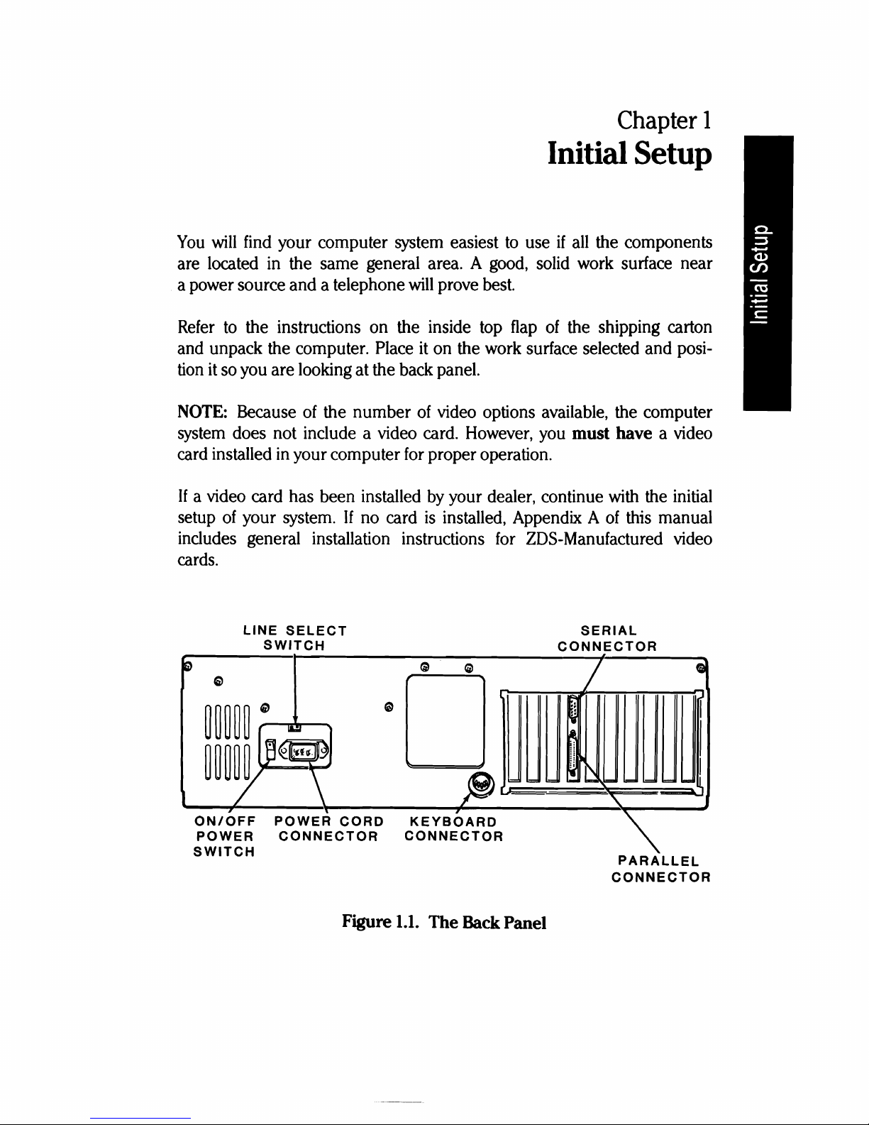
Figure
1.1.
The
Back Panel

Page
1.2
Initial
Setup
The Back Panel
The following switches
and
connectors are located on the back panel as
shown in Figure
1.1.
tine
Select Switch - This switch
is
used to select between
115
VAC
and 230
VAC.
You
should never use this switch unless, during initial
setup, you are in
an
area serviced by a 230
VAC
power source. (Check
local electrical codes.) Changing the setting on this switch should be done
only by qualified individuals. When the line voltage
is
changed, for exam-
ple,
115
VAC
to 230
VAC,
the line cord plug must be changed to the
proper type and voltage rating.
On/Off
Power Switch - The power switch
is
located on the left side
of
the back panel. Make sure the switch
is
in the OFF position before
you plug your computer into
an
outlet.
Power Cord Connector - When connected, the power cord supplies
power to the computer.
Keyboard Connector - A 5-pin
"DIN"
connector provides the necessary
signals for connection with the computer keyboard.
Serial Connector - The necessary EIA-standard RS-232 signals for con-
nection to a serial printer
or
other serial device are provided through
this 9-pin connector. A special cable
is
needed to connect a DB-25 output
to
this connector.
Parallel Connector - This 25-pin connector provides the necessary
parallel signals for connection to a Centronics-type parallel printer
or
other
parallel output device.
Page
1.3
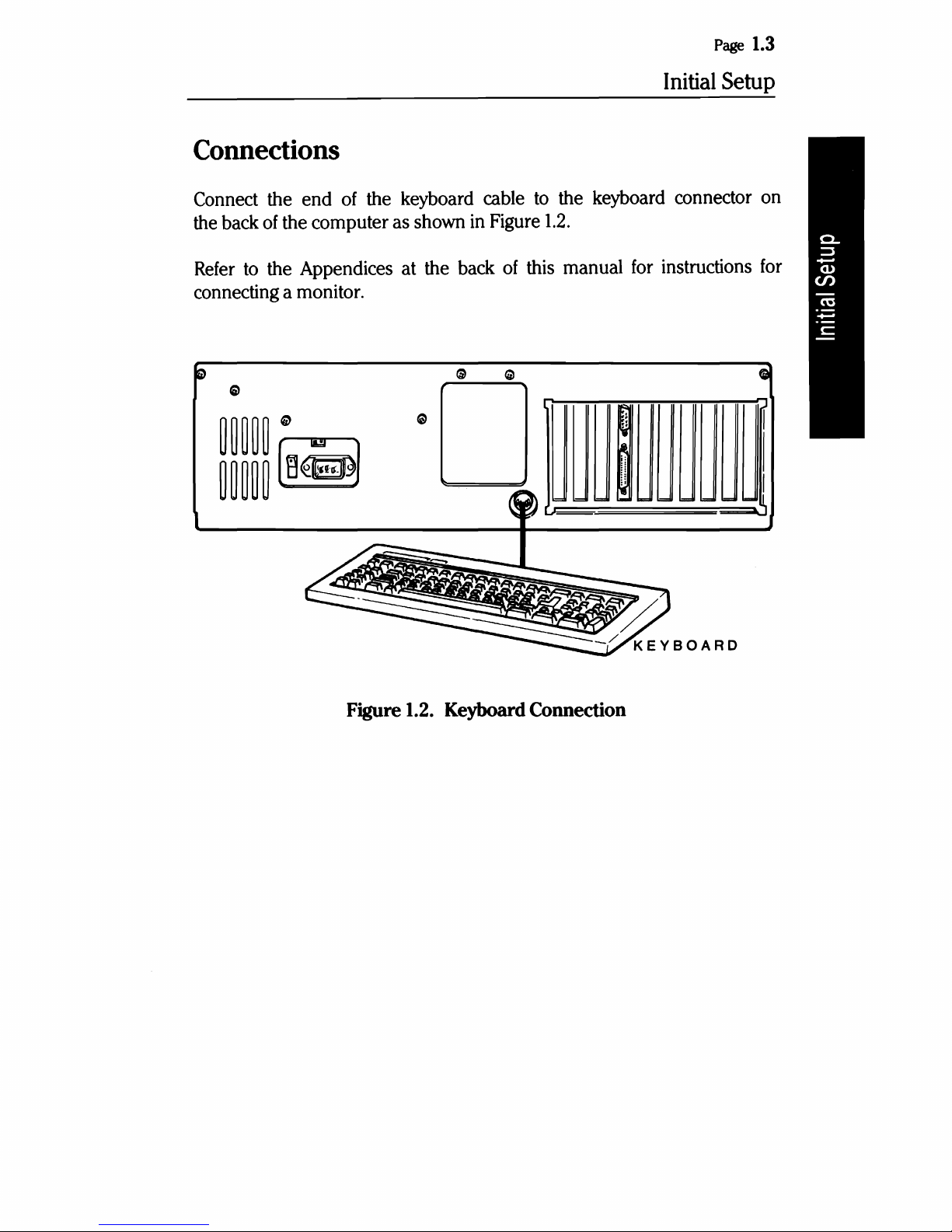
Connections
Connect the
the back of the computer as shown in Figure
Refer to the Appendices at the back
connecting a monitor.
end
of the keyboard cable to the keyboard connector on
of
this manual for instructions for
1.2.
Initial
Setup
~_/
~
Figure 1.2. Keyboard Connection
KEYBOARD

Page
1.4
Initial
Setup
If
your system components are not in their normal operating positions,
move them to their final position now. Reconnect any cables.
Up
to this
point, you should not have made any power connections.
CAUTION:
This computer system
is
designed to operate on either of two
different
AC
line voltages, either
115
VAC
at 60 Hz
or
230
VAC
at 50
Hz.
Before connecting the computer, make sure
it
is
rated for the voltage
available in your area. The computer
is
set at the factory for
120
volts,
the standard voltage in the United States. To change the voltage rating,
contact your authorized repair
facility.
• Before you connect any
of
your computer's components to
an
AC
power source, turn all power on/off switches
off.
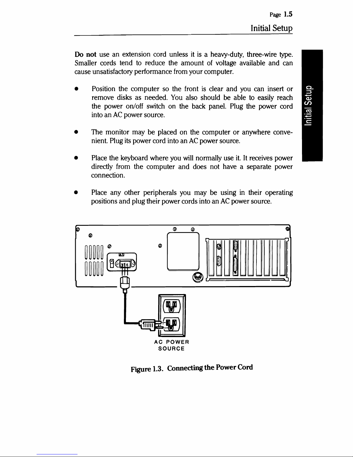
The computer
has
a detachable power cord. Refer to Figure
1.3
and
plug
the appropriate
end
of the power cord into the computer.
Do
not attach
the other
end
at this time.
With
multiple power cords involved, you may want
to
use a switched
multiple outlet box
or
power strip to turn on (or
off)
all system components
at the
same
time.
If
you do use a switched outlet box
or
power strip,
make sure
it
is
properly rated for your system's power needs (for
115
volt systems,
10
amperes; for 230 volts, 5 amperes).
Page
1.5
Initial Setup
Do
not use an extension cord unless
Smaller cords tend
cause unsatisfactory performance from your computer.
• Position the computer so the front
remove disks as needed.
the power on/off switch on the back panel. Plug the power cord
into an
• The monitor may be placed on the computer or anywhere conve-
nient. Plug
AC
to
reduce the amount
power source.
its
power cord into an
You
it
is
a heavy-duty, three-wire
of
voltage available and can
is
clear and you can insert or
also should be able
AC
power source.
to
easily reach
type.
• Place the keyboard where you
directly from the computer and does not have a separate power
connection.
• Place any other peripherals you may be using
positions and plug their power cords into an
to
e
~
~~~~~
"
G'
will
normally use
<W
AC
power source.
l
~
0
~~~~~
[ij¥J
@)
v:
====
it.
It
receives power
in
their operating
~
~
~
n
..
=-=1=
1=
""
1=1=_
Gl
r
I
I
~
AC
POWER
SOURCE
Figure 1.3. Connecting
the
Power Cord

Page
1.6
Initial
Setup
Powerup
and
Self-Tests
Normal Powerup
CAUTION: Before you turn on your computer system, be sure the
cardboard shipping insert has been removed from the disk drive.
The computer system's power may be turned on in any sequence, however,
never turn your system's power
on
or
off
with a disk
in
the floppy disk
drive; remove the disk
first.
There are two suggested sequences
for
turning on your system:
• One switch operation through a switched multiple outlet power box
or strip. The one switch on the box
or
strip
will
control the entire
computer system simultaneously.
• For most applications, apply power
to
your monitor
first,
then the
computer. Finally, turn on any other peripherals attached to your
computer system.
After the system
is
turned on, a number
of
things
will
happen: a small,
quiet fan
will
start; a light on the disk drive
will
come on; and the drive
will
make some sound as the "read/write heads" move back and forth.
Factory assembled computers are set
to
"autoboot" (automatically load
a disk operating system from a floppy or Winchester disk) when they
are shipped. One
of
the lights on the disk drives
will
come on and remain
on
in
a computer set for autoboot. If autoboot is started, a disk must
be placed in the drive
and
the door shut within about 20 seconds.
If
you want
to
reset the system by turning
it
off
and then on again, wait
at least
five
seconds before turning the computer on.
Page
1.7
Initial
Setup
Self-Tests
When
you
turn
on
your computer,
it
executes a series
of
internal
tests
to
check that everything
is
working
correctly.
These
tests
serve
several
important
functions.
First,
they
verify
that
all
of
the
circuits
are
in
a starting
configuration.
Second,
the
tests
check various
functions
of
the
computer
so
it
will
operate properly.
When
the tests are
finished,
the
computer
will
let
you
know
it
is
ready
to
run
by
displaying the opening
message,
or starting the automatic
boot
procedure (autoboot).
If
some
portion
of
the equipment
fails
to
operate
correctly,
the computer
will
attempt
to
display
an
error
message.
These messages and more
infor-
mation
on
the
initial
diagnostics
are included
in
the
In
Case
of
Difficulty
section
in
Chapter 3
of
this
manual.

Page
1.8
Initial
Setup
Keyboard
Keyboard Lock
The left side
of
the front panel includes a keyboard lock that
is
independent
of
the power switch.
When the key
is
in the unlocked (clockwise) position, the computer
is
fully
operational. In the locked (counterclockwise) position, the key can
be removed and the keyboard
is
disabled. The cover
is
locked on the
chassis - when the keyboard
is
locked.
An
extra key
and
a card referencing the key
number
and security code
are included in the box with your computer. These materials should be
kept in two different places.
If
a key gets lost, the extra key
or
the reference
card can
be
taken to a locksmith for a duplicate
key.
NOTE:
Zenith Data Systems can not duplicate a key according
to
the
serial
number
of
the computer. Keep your extra key
and
reference card
in
secure locations.
The keyboard of your computer contains 84 keys that are discussed in
the following pages.
Whenever you hold down any
key,
except the SHIFT,
CTRL,
ALT,
CAPS
LOCK,
SCROLL
LOCK,
or
NUM
LOCK,
it
will
start repeating. The rate
at which
it
repeats
will
gradually increase as you hold the key down.
Alphabetic Keys
Your personal computer has the standard 26 letters
of
the alphabet ar-
ranged as they are
on
a typewriter. These keys allow you
to
enter either
upper-
or
lowercase letters; hold down either SHIFT key
or
push the
CAPS
LOCK
key to obtain uppercase letters.
The
CAPS
LOCK
key
is
a push-to-engage, push-ta-release
key,
and affects
only the alphabetic keys. A light in the key indicates whether the feature
is
on (lit)
or
off
(unlit).
Page
1.9
Initial
Setup
EJEJ
'EJE]
EJEJ
EJEJ
EJEJ
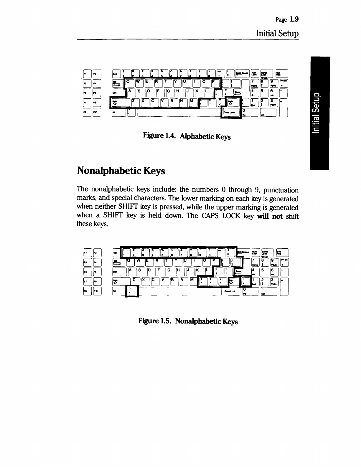
Figure 1.4. Alphabetic Keys
Nonalphabetic Keys
The nonalphabetic keys include: the numbers 0 through
9,
punctuation
marks,
and
special characters. The lower marking on each key
is
generated
when neither
SHIFf
key
is
pressed, while the upper marking
is
generated
when a
SHIFf
key
is
held down. The
CAPS
LOCK
key will
not
shift
these keys.
EJEJ
EJEJ
EJEJ
EJEJ
EJEJ
Figure 1.5. Nonalphabetic Keys
Page
1.10
Initial
Setup
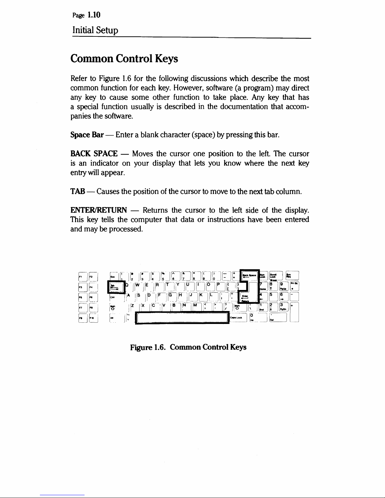
Common Control Keys
Refer
common
any
a
panies the
Space Bar - Enter a blank character (space)
BACK
is
entry
TAB
ENTERIRETURN
This
and
to
key
special
Figure
function
to
function
1.6
for
for
cause some other
usually
software.
an
indicator
will
SPACE
appear.
-
Moves
on
your display that
- Causes the position
- Returns the cursor
key
tells
the computer that data or instructions
may
be processed.
the
each
following
key.
discussions
However,
function
is
described
the cursor one position
lets
of
the cursor
software
to
in
the documentation that
you
to
move
to
take
by
know
the
which
(a
program)
place.
pressing
to
the
where the
to
the
left
side
have
describe the most
may
direct
Any
key
that has
accom-
this
bar.
left.
The
cursor
next
key
next
tab
column.
of
the
display.
been entered
Figure 1.6. Common Control Keys
Page
1.11
Initial
Setup
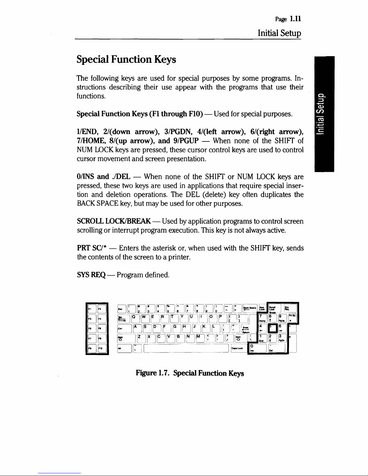
Special Function Keys
The
following
keys
are used
for
special purposes
by
some programs.
In-
structions describing their use appear
with
the programs that use their
functions.
Special Function Keys (Fl through FlO) -
Used
for
special purposes.
l/END,
2/(down arrow),
3/PGDN,
4/(left arrow), 6/(right arrow),
7/HOME,
8/(up arrow), and 9/PGUP -
When
none
of
the
SHIFT
of
NUM
LOCK
keys
are pressed, these cursor control
keys
are used
to
control
cursor movement and screen presentation.
O/INS
and JDEL -
When
none
of
the
SHIFT
or
NUM
LOCK
keys
are
pressed, these
two
keys
are used
in
applications that require special inser-
tion
and deletion operations.
The
DEL
(delete)
key
often
duplicates the
BACK
SPACE
key,
but may
be
used
for
other purposes.
SCROLL
LOCK/BREAK -Used
by
application programs
to
control screen
scrolling
or interrupt program execution.
This
key
is
not
always
active.
PRT
SC/*
- Enters the asterisk
or,
when used with the
SHIFT
key,
sends
the
contents
of
the screen
to
a printer.
SYS
REQ
- Program defined.
EJEJI
EJEJ
EJEJ
EJEJ
EJEJ
Figure
1.7.
Special Function Keys
Page
1.12
Initial
Setup
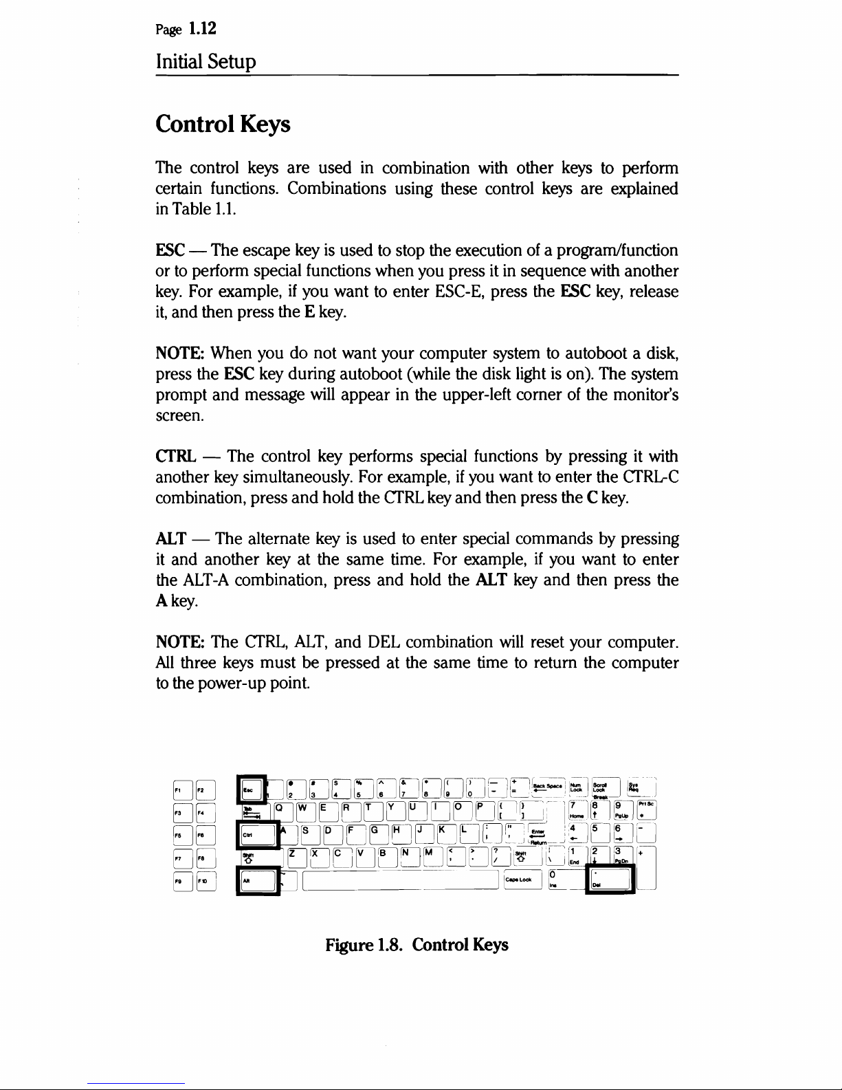
Control Keys
The control keys are used in combination with other keys to perform
certain functions. Combinations using these control keys are explained
in
Table
1.1.
ESC
- The escape key
is
used to stop the execution of a program/function
or
to
perform special functions when you press it in sequence with another
key.
For example,
if
you want to enter ESC-E, press the
ESC
key,
release
it,
and then press the E
key.
NOTE: When you do not want your computer system
to
autoboot a disk,
press the
ESC
key during autoboot (while the disk light
is
on). The system
prompt and message
will
appear in the upper-left corner
of
the monitor's
screen.
CfRL - The control key performs special functions by pressing it with
another key simultaneously. For example,
if
you want to enter the
CTRL-C
combination, press
and
hold the CfRL key and then press the C
key.
ALT - The alternate key
is
used to enter special commands by pressing
it
and another key at the same time. For example,
if
you want to enter
the
ALT-A
combination, press and hold the ALT key and then press the
A
key.
NOTE: The
CTRL,
ALT,
and DEL combination
will
reset your computer.
All
three keys must be pressed at the same time
to
return the computer
to
the power-up point.
EJEJ
EJEJ
EJEJ
EJEJ
EJEJ
Figure 1.8. Control Keys
Page
1.13
Initial
Setup
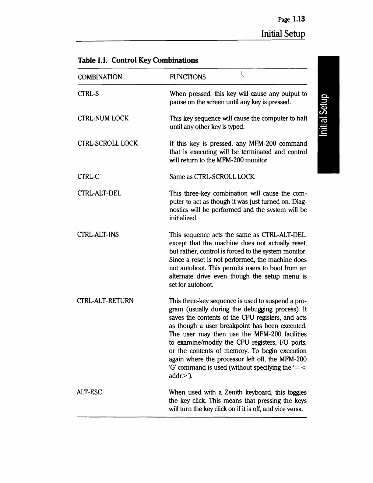
Table
1.1.
Control Key Combinations
COMBINATION
FUNCfIONS
CfRL-S
CTRL-NUM
LOCK
CfRL-SCROLL
LOCK
CfRL-C
CfRL-ALT-DEL
CTRL-ALT-INS
CTRL-ALT-RETURN
ALT-ESC
When
pressed,
this
key
will
cause any output
to
pause
on
the screen
until
any
key
is
pressed.
This
key
sequence
will
cause the computer
to
halt
until
any other
key
is
typed.
If this
key
is
pressed, any
MFM-200
command
that
is
executing
will
be
terminated and control
will
return
to
the
MFM-200
monitor.
Same
as
CfRL-SCROLL
LOCK.
This
three-key combination
will
cause the
com-
puter
to
act
as
though
it
was
just turned
on.
Diag-
nostics
will
be
performed and the
system
will
be
initialized.
This
sequence
acts
the same
as
CfRL-ALT-DEL,
except that the machine does not actually reset,
but rather, control
is
forced
to
the
system
monitor.
Since
a reset
is
not performed, the machine does
not autoboot
This
permits users
to
boot
from
an
alternate
drive
even though the setup menu
is
set
for
autoboot.
This
three-key sequence
is
used
to
suspend a pro-
gram (usually during the debugging process).
It
saves the contents
of
the
CPU
registers,
and
acts
as though a user breakpoint has been executed.
The user
may
then use the
MFM-200
facilities
to
examine/modify the
CPU
registers,
I/O
ports,
or the contents
of
memory.
To
begin
execution
again where the processor
left
off,
the
MFM
-200
'G'
command
is
used (without
specifying
the ' = <
addr>').
When
used
with
a Zenith keyboard,
this
toggles
the
key
click.
This
means that pressing the
keys
will
tum
the
key
click
on
if
it
is
off,
and
vice
versa.
Page
1.14
Initial
Setup
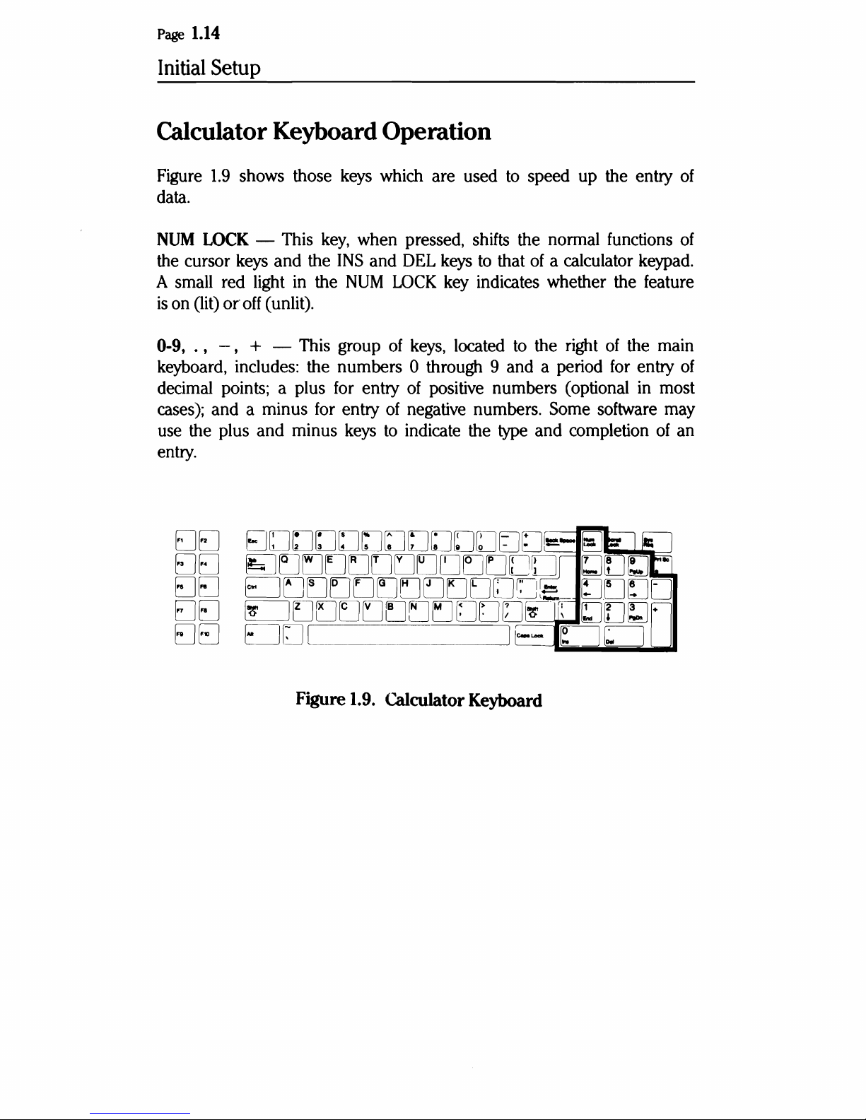
Calculator Keyboard Operation
Figure
1.9
shows those keys which are used
to
speed up the entry
of
data.
NUM
LOCK - This
key,
when pressed, shifts the normal functions
of
the cursor keys
and
the
INS
and
DEL
keys to that
of
a calculator keypad.
A small red light in the
NUM LOCK key indicates whether the feature
is
on (lit)
or
off
(unlit).
0-9,
.,
-,
+ - This group
of
keys, located to the right
of
the main
keyboard, includes: the numbers 0 through 9 and a period for entry
of
decimal points; a plus for entry
of
positive numbers (optional in most
cases); and a minus for entry
of
negative numbers. Some software may
use the plus
and
minus keys to indicate the type and completion
of
an
entry.
DEJ
EJEJ
EJEJ
EJEJ
EJEJ
Figure 1.9. Calculator Keyboard
Page
1.15
Initial
Setup
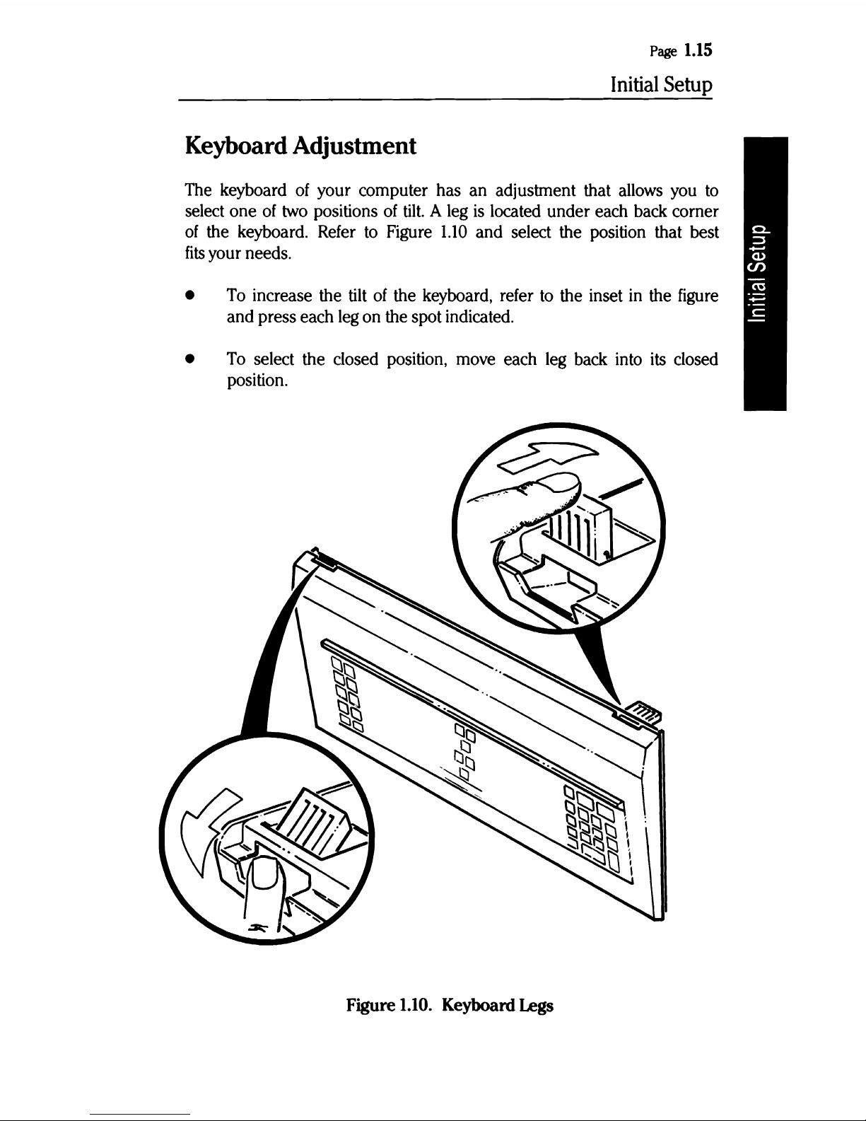
Keyboard Adjustment
The keyboard
of
your computer has an adjustment that allows you
to
select one
of
two positions
of
tilt.
A leg
is
located under each back corner
of
the keyboard. Refer
to
Figure
1.10
and select the position that best
fits
your needs.
•
To
increase the tilt
of
the keyboard, refer
to
the inset in the figure
and press each leg on the spot indicated.
•
To
select the closed position, move each leg back into its closed
position.
Figure
1.10.
Keyboard
Legs

Page
1.16
Initial
Setup
The SETUP
Program
The SETUP program serves as a reference, giving the computer informa-
tion about your system's configuration. The information you enter about
your system
is
kept in memory for all future uses and can easily be changed
if
you alter your configuration.
Type
SETUP
after the MFM-200 system prompt
(-
» and press the
RETURN
key to run the program.
If
your computer
is
set for autoboot,
press the
CfRL
and
ALT keys simultaneously and while holding them
down, press the
INS
key to get to the system prompt.
When the setup screen first appears, the standard selection in each
field,
or grouping,
is
already highlighted on the screen with a rectangular-shaped,
reverse-screen image.
You
can make your own selections by highlighting
the data which matches your system's configuration.
You
can move up, down,
left,
or
right between fields using the arrow
keys.
Within each field, except the time and date field, use the space
bar and
BACKSPACE
key
to
move between entries.
To
make a selection, move to the desired field and highlight the entry
that describes your system. This selection
will
be locked in when you
move
to
the next field.
The message area at the bottom of the screen
will
provide help and error
messages.
TIME
The time
and
date are the only entries that need
to
be typed in.
All
.
the other data
is
selected using the highlighted cursor.
The system's clock
is
battery-operated and
will
run continuously, even
when the computer is turned
off.
Therefore, you do not need
to
enter
a new time
and
date each time you turn the system on.

Page
1.17
Initial
Setup
The time clock operates
on
a 24 hour basis. For example, 2 p.m.
is
14:00
and
11
p.m.
is
23:00. The format for entering the time
is
hh:mm:ss, where
hh
is
the hour,
mm
is
the
number
of
minutes past the hour, and ss
is
the
number
of seconds into the minute.
The time must be entered in a two-digit format. For example, the hour
entry for 9 a.m.
is
09. It
is
not necessary to enter the colons between
the hours, minutes,
and
seconds. They
will
be entered automatically.
Example: 4:35 a.m.
is
entered as 043500.
4:35 p.m.
is
entered as 163500.
If the time is not entered correctly, an error message
will
appear at the
bottom of the screen. The cursor
will
not move past the entry until a
valid time
is
entered.
If you make a mistake while typing, use the
BACKSPACE
key to return
to
the position where you made the mistake and
type
over
it.
After entering the time, press the
RETURN
key
to
move
to
the date entry.
DATE
The date entry format
is
mm/dd/yyyy, where
mm
represents the month,
dd represents the day of the month, and
yyyy
represents the year. Note
that the numbers representing the month and day consist
of
two
digits,
while the year
is
represented by a four-digit number.
Example: March 21,1986
is
entered as 03211986.
It
is
not necessary to enter the slashes between the month, day, and
year. They
will
be
entered automatically. After entering the date, press
the
RETURN
key.
The time
and
date fields are the only ones which are entered using the
RETURN
key.
In the remaining fields, your selection
will
be locked in
when you move from a field using the arrow
keys.

Page
1.18
Initial
Setup
DST
The next field, to the right of the date and time,
If
stands for Daylight Savings Time.
area where Daylight Savings Time
year, you will want
be set backwards
to
or
forwards
enable this feature. The clock
one
you are operating the system in
is
in effect at some time during the
hour
on
the correct day.
Base Memory
Select your computer's base memory size by positioning the highlighted
512K
or
cursor over
640K, using the space bar
Expansion Memory
or
is
labeled
will·
the
BACKSPACE
DST,
which
an
automatically
key.
If your computer contains more than the maximum 640K
at
O.
number
then you need to select the
have added to the system. The selection ranges from 0
ments
backspace key
memory, set the
of
64K.
Use the space bar
to
choose a lower number.
number
of
bytes of expansion memory you
to
to
make the
If
you do not have any expansion
number
Floppy Drive 0
If you are using
between the 360K low-density drive,
each one that
DRIVE
0."
If
you do not have a floppy drive, choose
one
or
more tloppy disk drives, you need to choose
or
is
present. Your first floppy drive
the
1.2M
is
high-density drive for
referred
NOT
PRESENT.
Floppy Drive 1
If you are using a second floppy disk drive,
DRIVE
mats.
1."
Choose again between the 360K drive
If
you do not have a second floppy drive, choose
it
is
referred
and
the
NOT
of
base memory,
15,360 in incre-
higher
to
to
1.2M
PRESENT.
and
as "FLOPPY
as "FLOPPY
drive for-
the
Page
1.19
Initial
Setup
Boot Drive
The Boot Drive field allows you to set your default drive, which
is
the
drive the computer will autoboot first. Four options are available:
Option #1: The computer attempts to read the first floppy disk.
Option
#2:
The computer attempts to read the first Winchester disk.
Option
#3:
The computer attempts to read the first floppy disk and
if
a bootable disk
is
not found, continues
on
to the first Winchester
disk.
Option
#4:
The computer enters the MFM-200 monitor. The system
prompt
(-
»
will
appear
and
you can then boot from any drive
using the boot
('8') command.
Video Display
If
your system includes an optional color video card, select one
of
these
options:
Option #1: 40
x 25 for 40-character display
Option
#2:
80 x 25 for 80-character text display
Option
#3:
80 x 25 for monochrome display
Option
#4:
Enhanced graphics card
If
you have
an
optional high-resolution monochrome text display adapter
installed
and
plan
on
using it as the default display, select the monochrome
card.
Video Refresh Rate
The video refresh rate should
be
set according to the power line frequency
in
your area. In the United States, the
typical
power line frequency
is
60
Hz.
If
your system
is
not set correctly, the video screen
will
flicker.

Page
1.20
Initial
Setup
Winchester Drives
If you are using
one
or
more Winchester disk drives, you need to select
a drive type for each
of
them. Refer
to
Table
2.1
for the different types.
For a factory-installed drive, the type can be determined by the code
on the back panel. This code
is
arranged in 3-digit sets, each representing
one drive.
• The first 3-digit set represents the drive identifier code for floppy
driveA.
• The second 3-digit set represents the drive type identifier code for
either floppy drive B
(if
present)
or
Winchester drive
O.
• The third 3-digit set represents the drive type identifier code for
either Winchester drive 0
or
Winchester drive
1,
depending on
whether floppy drive B
is
installed.
• The fourth 3-digit set represents the drive type identifier code for
Winchester drive
1.
The maximum
of
12
digits indicates that four
drives are installed in the computer.
Position the highlighted marker over the drive
number
and, using the
space bar
and
backspace key, scan through the drive types
(1
to
15),
until you find the one which matches the data for your drive.
If
you
do not have a Winchester drive, select
NOT
PRESENT.
-------
-----
--
----
----------
--
-----
Page
1.21
Initial
Setup
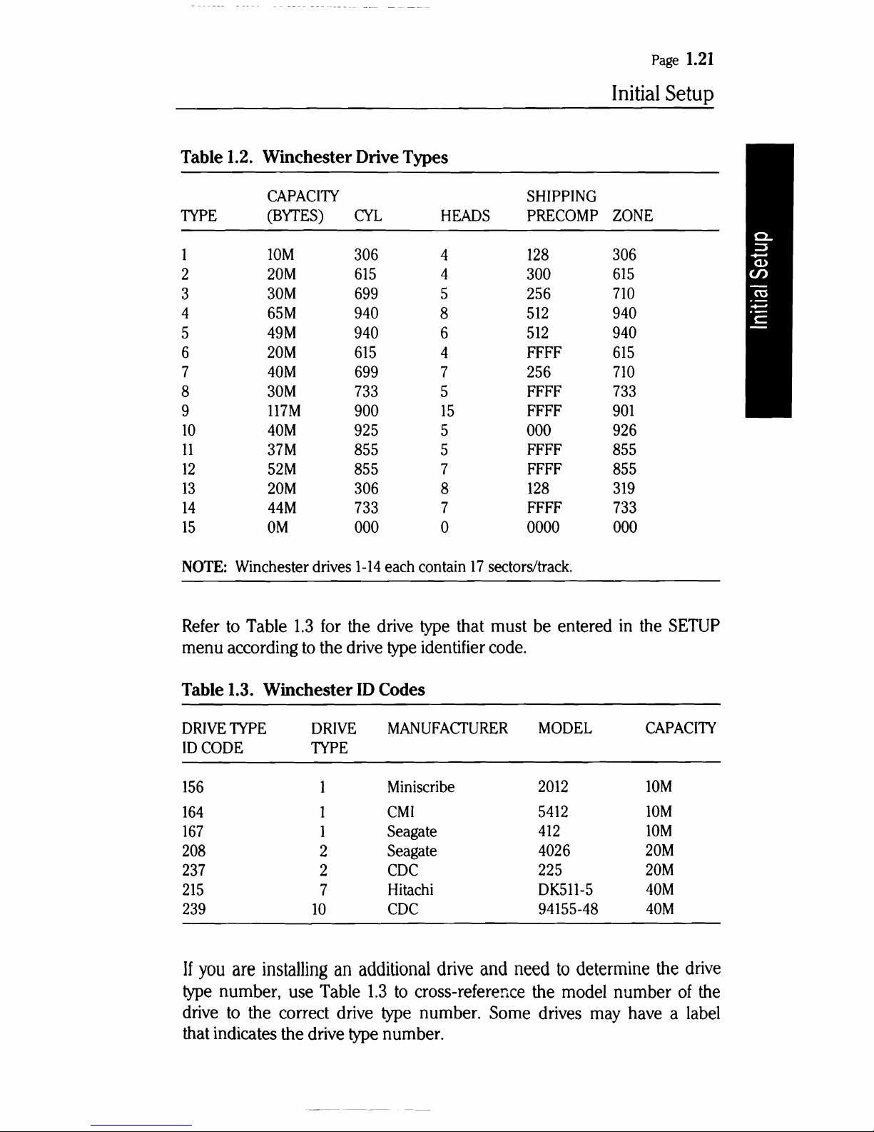
Table 1.2. Winchester Drive Types
CAPACITY
SHIPPING
TYPE
(BYrES)
CYL
HEADS
PRECOMP
ZONE
1
10M
306
4
128
306
2
20M
615
4
300
615
3
30M
699
5
256
710
4
65M
940
8
512
940
5
49M
940
6
512
940
6
20M
615
4
FFFF
615
7
40M
699
7
256
710
8
30M
733
5
FFFF
733
9
117M
900
15
FFFF
901
10
40M
925
5
000
926
11
37M
855
5
FFFF
855
12
52M
855
7
FFFF
855
13
20M
306
8
128
319
14
44M
733
7
FFFF
733
15
OM
000
a
0000
000
NOTE: Winchester drives
1-14
each contain
17
sectors/track.
Refer to Table
1.3
for the drive type that must be entered in the SETUP
menu according to the drive type identifier code.
Table 1.3. Winchester
ID
Codes
DRIVE
TYPE
DRIVE
MANUFACfURER
MODEL
CAPACITY
IDCODE
TYPE
156
1
Miniscribe
2012
10M
164
1
CMI
5412
10M
167
1
Seagate
412
10M
208
2
Seagate
4026
20M
237
2
CDC
225
20M
215
7
Hitachi
DK511-5
40M
239
10
CDC
94155-48
40M
If
you
are
installing
an
additional
drive
and
need
to
determine
the
drive
type number, use Table
1.3
to
cross-reference the model number
of
the
drive to the correct drive type number. Some drives may have a label
that indicates the drive type number.
 Loading...