

Page 1
Page 2

Regulatory and Registration Information
WARNING - This equipment has been certified to comply within the limits established for a
Class B computing device, pursuant to Subpart J of Part 15 of the rules established by the
FCC. Only peripherals (computer input/output devices, terminals, printers, etc.) certified to
comply within these Class B limits may be attached to this computer. Operation with non-certified
peripherals is likely to result in interference to radio and TV reception.
This equipment generates and uses radio frequency energy for its operation; and if not properly
installed and used, that is, in strict accordance with the instructions in this manual, may cause
interference to radio a nd tele vision re cepti on. It has b een type-t este d and found to be within the
RF emission limits for a Class B computing device which is intended to provide reasonable
protection against such interference in a residential environment. However, there is no
guarantee that interference will not occur in any particular environment or location. If this
equipment does cause interference to radio and television reception, which can be determined by
turning this equipment on and off, t ry to correct the interference by one of more of the following
measures.
• Move the computing device away from the equipment receiving the interference.
• Relocate the computing device with respect to the receiver.
• Reorient (turn) the antenna of the receiving equipment.
• Plug the computing device into a different AC outlet so that the computing device and
receiver are on separate circuits from the fuse or circuit breaker box.
• Disconnect an d remove any input/output cables that are not being used since unterminated input/output cables are a potential source of high RF emission levels.
• Unplug and remove any serial input/output circuit board cards that are not being used
since unterminated cards can be a potential source of interference.
• Make sure that the computing devices are plugged into grounded outlet receptacles.
Avoid using AC two- to three-wire cheater plugs. Lifting or removing the power cord
ground may increase RF emission levels. Removing the ground circuit also may cause a
lethal shock hazard to the user.
If you need additional help, consult your dealer or ask for assistance from the manufacturer. Yo u
may also find the following booklet helpful: How to Identify and Resolve Radio-TV Interference
Problems. This booklet is available from the U.S. Government Printing Office, Washington, DC
20402, stock number 004-000-00345-4.
Registration
To receive the full benefits of your warranty, complete and mail the accompanying registration
card. Also, record the series and serial numbers of your equipment below. Refer to these
numbers in any correspondence you have with Zenith Data Systems regarding this equipment.
Model
Serial Number ___________________________
Series
Place purchased ____________________________________________________________
Any attempt to alter or modify the design, or to use this device in a manner other than described in
this manual, will void the warranty and release the manufacturer from any responsibility for it s
operation.
Date purchased _________________________
Page 3

Z-100 Series
Computers
User's Manual
Page 4

Contractor is Zenith Data Systems Corporation of St. Joseph, Michigan 49085. The
LIMITED RIGHTS LEGEND
entire document is subject to Limited Rights data provisions.
RESTRICTED RIGHTS LEGEND
This computer software and documentation are provided with RESTRICTED RI GH T S .
Use, duplication or disclosure by the Government is subject to restrictions is set
forth in the Governing Rights in Technical Data and Computer Software clause –
subdivision (b)(3)(B) of DAR 7-104.9(a) (May 1981) or subdivision (b)(3)(i i ) of DOD FA R
Supp 252.227-7013 (May 1981). Contractor/Manufacturer is Zenith Data Systems
Corporation, or Hilltop Road, St. Joseph, MI 49085.
Copyright 1982, 1985 by Zenith Data Systems Corporation.
Printed in the United States of Amer ica.
Zenith Data Systems Corporation
St. Joseph, Michigan 49085
Page 5

Page 6
Welcome
Congratulations on you r purchase of the Zenith Data Systems Z-100 Series
Computer. The Z-100 microcomput er represents a truly state-of the-art design,
capable of satisfying both your business and personal needs.
With the Z-1 00 Computer - the All-in-One model or the Low-Profile model - the
future is here today. The Z-100 Computer can act as a simple tool or function
as the heart of a powerful and expandable business automation package.
Combined with Zenith Data Systems software, your new Z -1 00 Co mp ut er
can easily provide the practical and affordable solutions to your
business problems. It can easily satisfy a variety of business applicat ions, such
at data processing, telecommunications, networking, and financial analysis to
aid you in making those all-important business decisions.
This User's Manual has been prepared for you, the new computer owner and
user. Welcome to computing at its best and accept Zenith's assurance and
commitment that the quality goes in before the name goes on.
iii
Page 7

iv
Page 8

Preface
This User's Manual is divided into four sections for easy use:
• Operat ion - Th e beginning section t ells you how to set up your new Z -100
Computer. Then you will turn it on and be introduced to the keyboard and
controls. You will learn about disks and how to use a special
demonstration disk. And finally, there is a section on what to do if you
have a problem with your computer.
• Disk Operating System - This chapter will help you understand and use
your computer. In addition, it will show you how to make extra copies
(called "backups") of the information stored by your computer.
• Computer Programming and BASIC - Here you will be briefly introduced to
the world of programming and learn how to give instructions to your
computer in BASIC, one of the most popular computer "languages."
• Appendices - This last section contains reference material that you may find
informative. It also contains step-by-step disassembly and assembly
information that replaces the equivalent instructions in the installation
manual included with any accessories you may purchase for your
computer.
You will want to become familiar with your computer's many features.
This manual will help you get the most out of your new Zenith Data Systems
Z-1 00 Computer.
v
Page 9

vi
Page 10

Contents
Welcome iii
Preface
Chapter 1 Operation
Your Computer System 1-1
Setting Up 1-3
Back Panel 1-3
Power Connection 1-7
Keyboard 1-8
Alphabetic Keys 1
Nonalphabetic Keys 1-9
Other Keys 1-10
Disk Drives 1-13
Disks 1-15
Disk Care 1-18
Power Up 1-19
Z-100 Demonstration Disk 1-20
Introduction 1-20
Master Menu 1-22
Artwork 1-22
Interactive Business Graphics 1-23
In Case of Difficulty 1-26
Service Information 1-29
When You Call for Help 1-29
-
V
8
Chapter 2 Disk Operating System
Introduction 2-1
The Monitor Program 2-2
Autoboot 2-2
The Commands 2-3
B – Boot 2-4
C – Color Bar 2-5
H – Help 2-6
S – System 2-7
V – Version 2-7
Loading MS-DOS 2-8
The MS-DOS Prompt 2-11
Making A Backup 2-11
Backups 2-11
Backing Up Your Disks the First Ti me 2-12
Labeling Disks 2-14
vii
Page 11

MS-DOS Co n tr o l K e y Fu nc t i o n s ...........................................................................2-16
MS-DO S Commands ............................................................................................2-19
Changin g MS-DOS Prom p t s ............................................................................2-19
Error M e ss a g es ................................................................................................2-20
Files, Programs, and File Names .....................................................................2-21
Internal Commands ..........................................................................................2-22
COPY ........................................................................................................2-23
DATE ........................................................................................................ 2-24
DIR ............................................................................................................ 2-24
Wild C ards .................................................................................................2-26
Multipl e Di r e c to r ies ....................................................................................2-27
ERASE (DEL) ............................................................................................ 2-32
RENAM E (R E N ) ........................................................................................2-33
TIME ......................................................................................................... 2-33
TYPE ........................................................................................................2-34
VER ........................................................................................................... 2-34
VERIFY ..................................................................................................... 2-35
VOL ........................................................................................................... 2-35
Other In t e rn al C o m ma n d s .........................................................................2-36
Externa l C o mm a n ds .........................................................................................2-36
C H K D S K ....................................................................................................2-38
FORMAT ...................................................................................................2-39
SYS ........................................................................................................... 2-43
DISKC O PY ................................................................................................2-43
DISKCOMP ............................................................................................... 2-45
Other External M S-DOS Com mands .........................................................2-47
Chapte r 3 Com puter Programming and BASIC
Programs .................................................................................................................. 3-1
Progr a m Ty p e s ......................................................................................................... 3-1
Programmers ............................................................................................................ 3-2
Programming Languages .........................................................................................3-2
Syntax ................................................................................................................ 3-2
Languag e Ty pes ................................................................................................3-3
Underst a nd i n g BA SIC ............................................................................................... 3-6
Getting Started with BAS I C ................................................................................ 3-6
Loading BASIC ...................................................................................................3-7
BASIC Modes of Operation ..........................................................................3-8
Statements .................................................................................................. 3-9
Direc t M o de O p e ra t i o n .................................................................................3-9
Variables ................................................................................................... 3-11
Varia ble Ty p e s ..........................................................................................3-11
viii
Page 12

Programming in BASIC ........................................................................................... 3-12
Using th e In d i re c t M o d e of B ASIC ........................................................................... 3-12
Saving and Loadi ng Programs ................................................................................3-14
Designi ng a Prog ram ..............................................................................................3-15
Program Purpose ....................................................................................................3-16
Breakdown ..............................................................................................................3-17
Detaile d Steps .........................................................................................................3-17
Conversion .............................................................................................................3-19
Summary ................................................................................................................3-26
Appendi x A A Glossary of Commonly-Used Computer Terms
Appendix B Symbols and Codes
Appendix C Monitor Program Command Summary
The Monito r Progr a m Commands ............................................................................. C-2
Boot ......................................................................................................................... C-2
Colo r B a r .................................................................................................................. C-4
Dump .......................................................................................................................C-4
Examine ................................................................................................................... C-5
Fill .............................................................................................................................C-5
Help ......................................................................................................................... C-6
Input ......................................................................................................................... C-6
Output ......................................................................................................................C-6
System .................................................................................................................... C-7
Test ..........................................................................................................................C-7
Version ......................................................................................................................C-8
Execute .....................................................................................................................C-8
Appendix D MS-DOS Command Summary
Command Summary .................................................................................................D-1
Commands............................................................................................................... D-2
MS-DOS With Single Drive C omputers .....................................................................D-8
Appendix E BASIC Command Summary
BASIC Commands, Functions , and Statements ........................................................E-5
ix
Page 13

Appen di x F System Configuration
The CO NFIGUR Util i t y ..............................................................................................F-2
Displ a y 1 ............................................................................................................F-3
Disp l a y 2 ............................................................................................................F-4
Display 3 ............................................................................................................F-5
Displ a y 4 ............................................................................................................F-6
Display 5 ............................................................................................................F-7
Displ a y 6 ............................................................................................................F-8
Display 7 ............................................................................................................F-9
Display 8 ..........................................................................................................F-10
Display 9 ..........................................................................................................F-11
Display 10 ........................................................................................................F-12
Display 11 ........................................................................................................F-13
Display 12 ........................................................................................................F-14
Display 13 ........................................................................................................F-14
Display 14 ........................................................................................................F-15
Display 15 ........................................................................................................F-15
Display 16 ........................................................................................................F-16
Display 17 ........................................................................................................F-16
Display 18 ........................................................................................................F-16
Displ a y 19 ........................................................................................................F-17
Displ a y 20 ........................................................................................................F-17
Printer Configu r ation ...............................................................................................F-17
Appen di x G Changing Hardware Configuration
Disassembly .............................................................................................................G-1
All-in- O n e M o d e l ............................................................................................... G-2
Low-Profile Model ............................................................................................. G-6
Final D i sassembly ........................................................................................... G-10
Reassembly ........................................................................................................... G-12
All-in-One Reassembly ................................................................................... G-14
Low-Profile Model ........................................................................................... G-18
Swit ch S1 0 1............................................................................................................G-22
Floppy D isk Cont roller DS1 Switch S ettings ........................................................... G-24
Video Board Jumpers ............................................................................................ G-26
Appendix H System Specifications
x
Page 14

Appendix I CP/M-85 Disk Operating System
Appendix J Using Z-89 Software on the Z-100
Tran s f e r Pro c e d u r e One ............................................................................................ J-2
Equipme nt Needed ................................................................................................... J-2
Transfer Procedure .........................................................................................................
5.25-in ch Source Disks .............................................................................................J-4
8-inch S o u rc e D i s ks .................................................................................................. J-5
Trans fer Pr o c e dure Two ............................................................................................ J-6
Equipme nt Needed ...................................................................................................J-6
Transfer Procedure ...................................................................................................J-6
Transfer Procedure Three .........................................................................................J-8
Equipme nt Needed ................................................................................................... J-8
Transfer Procedure ...................................................................................................J-9
Convert ible Soft ware ............................................................................................... J-11
Magic W a nd Functi o n Key Gui d e ............................................................................ J-14
Appendix K Interactive Business Graphics
Introduction ...............................................................................................................K-1
The Inte r a ct i v e B u s i n e s s G r ap h i c s Pr o g r a m .............................................................K-1
The Data Management Routines ..............................................................................K-3
Create Ne w D a t a Fi l e ................................................................................................K-3
Modify Ex i sting Dat a Fi l e ...........................................................................................K-6
Print Existing Da t a File .............................................................................................K-8
Graphic Design R outine ............................................................................................K-8
Displaying the Graph ..............................................................................................K-12
J-3
Appendix L Backups
Using t h e DISKCOPY Utility to Make Backups .......................................................... L-1
Using the FO R MAT and COPY P ro c e d u re t o Ma ke B ac k u p s ................................... L-4
FORMAT ...................................................................................................................L-4
COPY ........................................................................................................................L-7
Creatin g Bootabl e MS-DOS Di sks for Y o ur Applic ations ...........................................L-8
Index
xi
Page 15

Figures
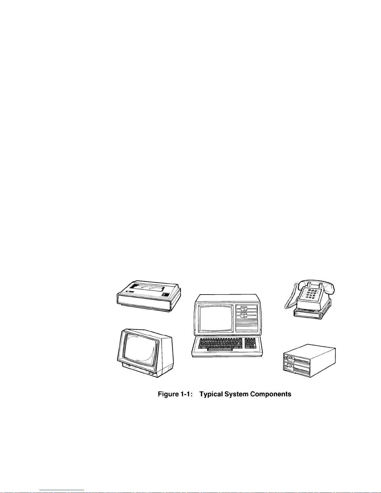
1-1: Typical System Components ................................................................1-1
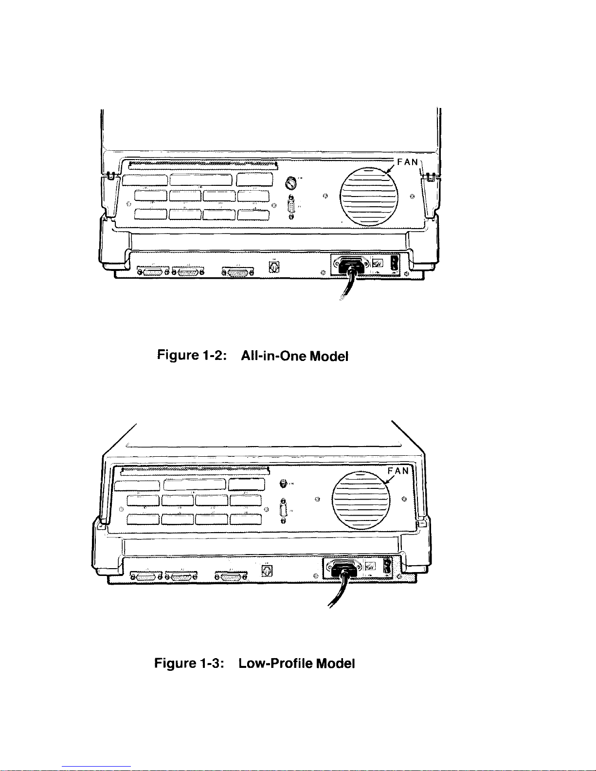
1-2 All-in-One Model ...................................................................................1-4
1-3: Low-Profile Model .................................................................................1-4
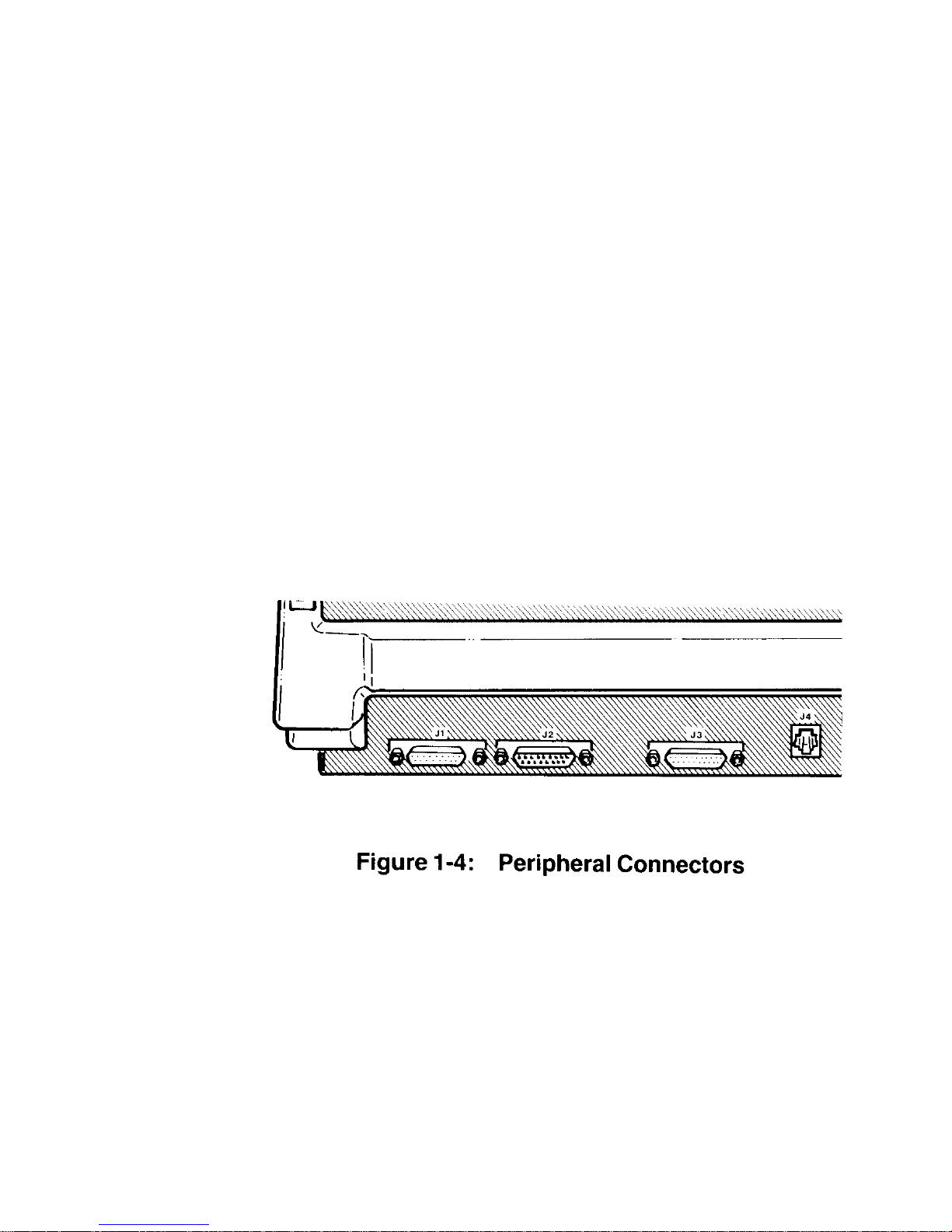
1-4: Peripheral Connectors ..........................................................................1-5
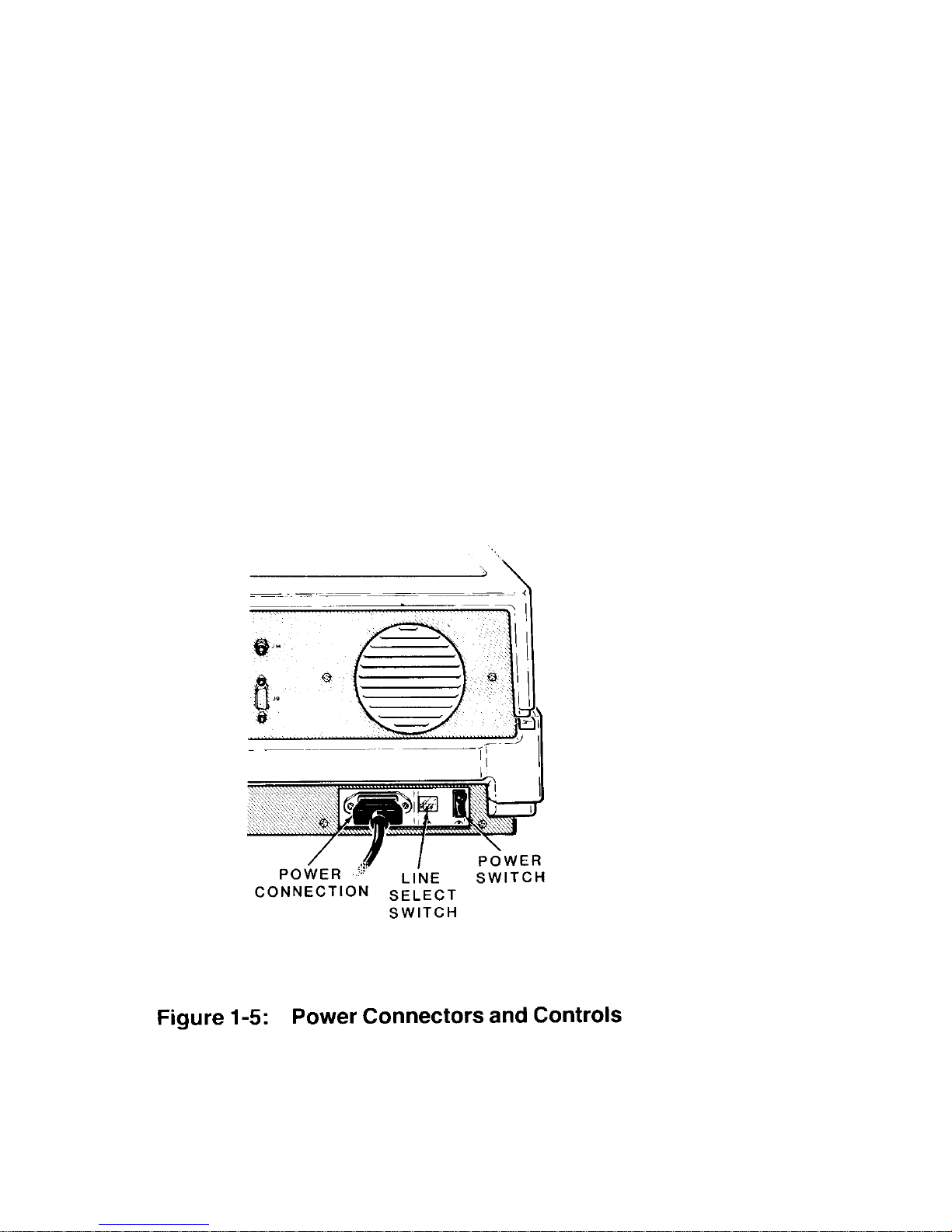
1-5 . Power Connectors and Controls ...........................................................1-6
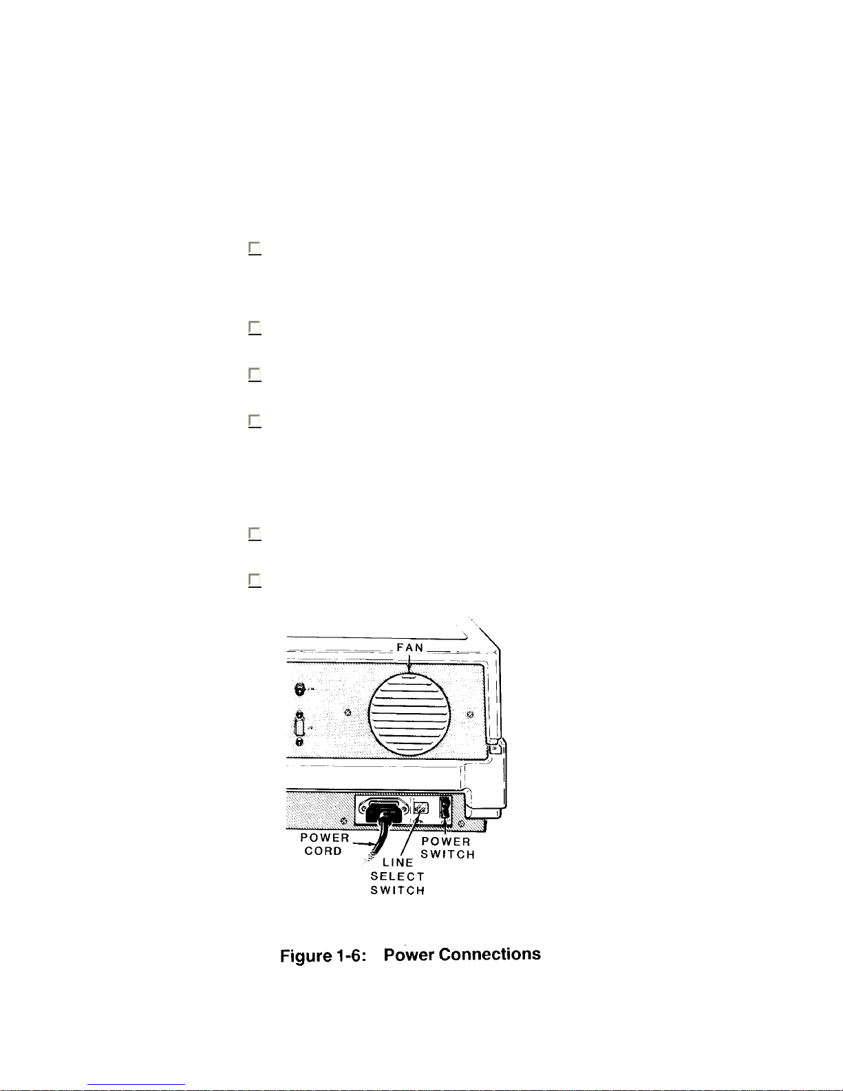
1-6: Power Connections ............................................................................... 1-7
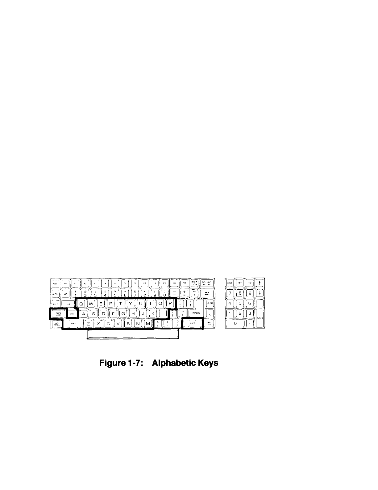
1-7: Alphabetic Keys ....................................................................................1-8
1-8: Nonalphabetic Keys ..............................................................................1-9
1-9: Other Keys...........................................................................................1-10
1-10: Special Purpose Keys ......................................................................... 1-11
1-11: Control Keys and Numeric Keypad .....................................................1-12
1-12: All-in-One Model .................................................................................1-13
1-13: Low-Profile Model ...............................................................................1-13
1-14: Disk Drive Controls .............................................................................1-14
1-15: Disks ....................................................................................................1-15
1-16: Disk Surface ........................................................................................ 1-17
1-17: Business Graphics Menu ....................................................................1-24
3-1: A Comparison of Language Types .......................................................3-5
G-1: All-in-One Cabinet Removal ................................................................G-2
G-2: Unfastening the Drive/Video Subassembly ..........................................G-3
G-3: Disconnecting the Floppy Disk Drives ................................................. G-4
G-4: Disconnecting the Winchester Disk System ........................................G-5
G-5: Removing the Top Case ......................................................................G-6
G-6: Unfastening the Drive Subassembly ....................................................G-7
G-7: Disconnecting the Floppy Disk Drives ................................................. G-8
C-3: Disconnecting the Winchester Disk Drive ............................................G-9
G-9: Removing the Keyboard/Base Cover .................................................G-10
G-10: Removing the Video Board ................................................................ G-11
G-11: Installing the Video Board .................................................................. G-12
G-12: Installing the Keyboard/Base Cover ...................................................G-13
G-13: Connecting the Signal/Power and Floppy Disk Drive Cables.............G-14
G-14: Connecting the Winchester Disk Drive ..............................................G-15
G-15: Fastening the Drive/Video Subassembly to the Base ........................G-16
G-16: Replacing the Cabinet Top ................................................................G-17
G-17: Connecting the Floppy Disk Drive Cables .........................................G-18
G-18: Connecting the Winchester Disk Drive ..............................................G-19
G-19: Fastening the Drive Subassembly and Base ..................................... G-20
G-20: Switch S101 (Main Board) ................................................................. G-21
G-21: RGB Connector (J9)............................................................................G-22
G-22: Switch DS1 (Floppy Disk Card) .........................................................G.24
G-23: RGB Connector J9..............................................................................G-26
G-24: Video Board Jumpers..........................................................................G-27
xii
Page 16

Tables
2-1: Monitor Command Summary ................................................................. 2-3
2-2: Internal MS-DOS Comm and s ..............................................................2-22
2-3: External MS-DO S Co mm an d s ( Ut i lit i es ) .............................................. 2-37
2-4: FORMAT Switches ..............................................................................2-40
3-1: Sources of Some High-Level Language Names ..................................... 3-4
3-2: Sample Out p u t from B AS I C .................................................................3-24
B-1: T h e A S C I I C h a r a c t e r S e t .......................................................................B-2
B-2: Hexadecimal Key Codes .......................................................................B-5
B-3: ASCII Key pad Codes - Key Expansi on Mode E nabled ..........................B-9
B-4: ASCII Function Key Codes - Key Expansion Mode Enabled................. B -1 0
B-5: Escape Codes - Cursor Functions .......................................................B-10
B-6: Escape Codes - Erasing and Editi ng ...................................................B-11
B-7: Escape Codes - Mo des of Op erat ion ...................................................B-11
B-8: Escape Codes - Configuration .............................................................B-12
B-9: Escape Codes - Addi tional Functi ons ..................................................B-14
C-1: Monitor Prog ram Co m m and S um ma ry ..................................................C-1
C-2: Monitor Prog ram Sy nt a x No ta ti o n ......................................................... C-2
D-1: Control Key Functions ...........................................................................D-1
D-2: File Name Conv en ti on s .........................................................................D-1
E-1: Control Characters .................................................................................E-1
E-2: Variable Specifications ..........................................................................E-2
E-3: Arithmetic Operators ..............................................................................E-3
E-4: Relational Operators ..............................................................................E-3
E-5: Logical Operators ..................................................................................E-3
E-6: Truth Table for Logical Operators ..........................................................E-4
E-7: BASIC Color Attributes ...........................................................................E-4
E-8: String Operators ....................................................................................E-4
E-9: Arrays ....................................................................................................E-4
E-10: Directions Recognized by the DRAW Statement ....................................E-9
E-11: USING Field Specifiers ........................................................................E-17
E-12: Image T r a n sf e r A c t i o n V e r b s ................................................................E-18
F-1: Devices Directly Supported by CONFIGUR ............................................F-1
G-1: S1 0 1 S w i t c h Settin gs .......................................................................... G-23
G-2: DS1 Fl o pp y D is k C on t r ol l er S wi t ch Se tt i ngs ....................................... G-25
G-3: RGB Connector (J9) Pinouts ............................................................... G-26
G-4: Video Board Jumpers .........................................................................G-27
xiii
Page 17

1-1: MS-DOS and C P/M-85 Control Functions ...................................................1-1
1-2: MS-DOS and CP/M-85 Comman d s .............................................................1-2
J-1: Convertible CP/M-80 Software .................................................................. J-11
J-2: Magic Wand Z-89 to Z - 1 0 0 Fu n c t i on K e y Gu i de ........................................J-14
K-1: Graph Display Types ..................................................................................K-9
K-2: Chart Specifications.......................................................................................K-10
xiv
Page 18

Page 19
Chapter 1 Operation Page 1-1
Your Computer System
Your new Z-100 Computer is a tool, much like a typewriter or calculator.
You can use it in a wide number of applications, such as general accounting,
inventory management, payroll, communications, maintaining mailing lists,
filing and retrieval of information, and word processing. It is also an
excellent educational aide that can make the learning process fun and
challenging for the student while providing management support for the
teacher and school.
Your computer is an extremely reliable machine. When it is pro perly installed
and receives proper care, it will last for years with little need for service.
A typical computer system will consist of at least two units: the computer
and a peripheral (any piece of equipment that is attached to and controlled by
the computer). It may be a video display, printer, telephone communications
device (called a modem), or additiona l di sk drive s.
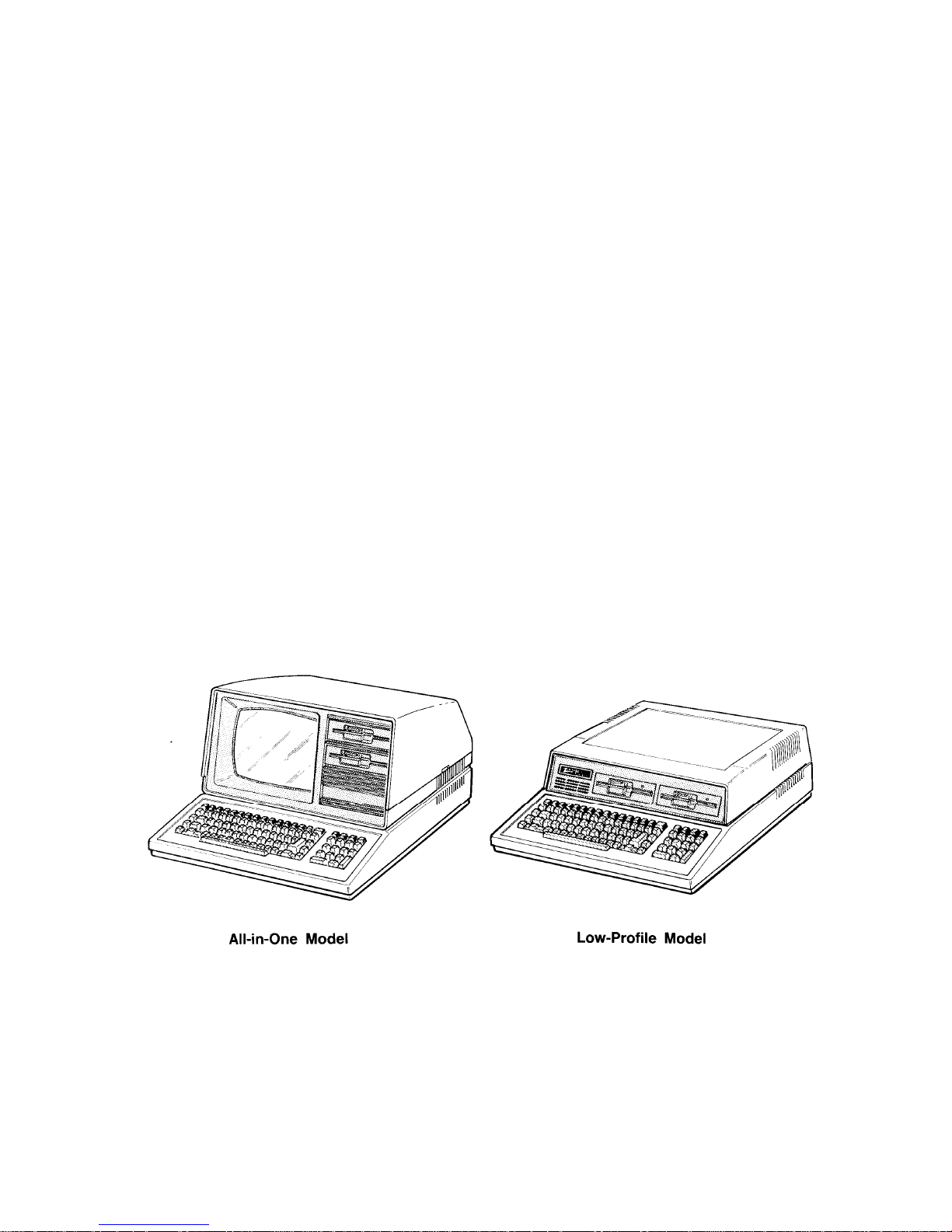
The heart of the system is the computer with its keyboard and st or age devices.
The All-in-One model, shown in Figure 1-1, also contains a built-in video
display.
Page 20

Chapter 1 Operation Page 1-2
The video display (sometimes called the CRT, monitor, or screen) is like a
television set. This is where you will see and work with the programs you
use in your computer system. The Low-Profile model does not have a builtin video display; it uses a separate video monitor that is connected to the
computer with a cable.
You will use the keyboard to enter information into your computer. It has all
the keys contained on a standard typewriter keyboard plus additional
special function keys. There is also a calculator-style "keypad" to the right of
the main keyboard that will allow you to make faster numeric entries.
(information can also be placed in the computer from disks, signals over
telephones lines, and other special devices.)
The floppy disk capability that is built into your computer allows you to store
large amounts of information on 5.25-inch plastic disks (see Disks later in
this chapter). Each disk that your c omputer uses is capable of holding up
to 180 pages of typewritten text. You can get even more storage by adding 8inch floppy disk drives or a high-capacity Winchester disk drive.
You can greatly enhance the operation of your computer by adding a printer to
your system. This makes it possible to produce copies of letters, accounting
records, or any other material.
Finally, you may add computer-to-computer communications via telephone.
This capability makes it possible for your computer to exchange information
with other computers over the telephone, which makes available electronic
mail service, news, shopping services, electronic banking and bill paying,
stock market services, and so on.
You should select an area to set up your computer that:
• accommodates the computer and all of its peripherals.
• has a level work surface that is near a power source and a telephone.
• has an environmental range of 60 to 90 degrees Fahren heit (15.6 to
32.2 degrees Celsius) and 10 to 80 percent relative humidity.
Page 21

Chapter 1 Operation Page 1-3
Setting Up
The following paragraphs will describe setting up each connector and control
on your computer. While examining the back panel and the connectors, be
sure that the computer is turned off and unplugged. Rotat e the computer so
you are looking at its back.
Back Panel
Refer to Figure 1-2 for the All-in-O ne model and to Figure 1-3 for the LowProfile model.
• Fan – Used to provide ventilation to the power supply. Never block the fan
openings or restrict air movement wh ile you hav e your co mputer turned on.
The following control and connector(s) are located next to the fa n openings on
the upper back panel.
• J15 -- The brightness control. Used to adjust the bri ghtness of the video
display. Adjust the brightness to obtain the most suitable display. (All-inOne model only.)
• J15 – The composite video output connector. Provides the proper video
signal for a separate black and white (monochrome) video monitor. The
Low-Profile model requires a separate video monitor; you cannot use a
standard television receiver for this pur pose as it is not designed to displa y
all of the information needed for word processing or accounting
applications.
• J9 – The RGB video output connector. Provides the nec essary signals f or
a high-resolution color monitor that uses RGB (Red, Green, Blue) color
signals. Appendix G contains the necessary info rmation that you need to
configure this connector.
In addition to the above control and connectors, on the upper back panel
there are a number of unfilled positions (J5-J8, J1-J13, J15, and J17). Any
necessary controls and/or connectors needed for future expansion will be
provided with the optional accessories.
Page 22
Chapter 1 Operation Page 1-4
Page 23
Chapter 1 Operation Page 1-5
Refer to Figure 1-4. These connectors are on the lower-left portions of the back
of your computer.
• J1 – A serial connector. Provides the necessary EIA-standard RS-232 DCE
signals for connection to a serial printer.
• J2 – A serial connector. Provides the necessar y EIA-standard RS-232 DTE
signals for use with a telephone mo dem.
• J3 – The parallel printer connector. Provides the necessary Centronicstype parallel signals for connection to a pa ralle l pr inter .
• J4 - The light pen connector. Provides the necessary signals for
connection to a light pen for on-screen graphics work.
Page 24
Chapter 1 Operation Page 1-6
Refer to Figure 1-5. These features are located on the lower-right portion of
the back panel.
• Power cord connector – Used with the AC p ower cord to supply power to
the computer.
• Line select switch – Used to select between 115 volts AC and 230 volt s
AC. Normally, you will never use this switch unless (during initial setup)
you are in an area serviced by a 230 volts AC power source. (Changing the
setting on this switch should be done only be qualified i ndivi duals . When
changing line voltage, i.e., 115 to 230, the line cord plug must be
changed to the proper type and voltage rating. Check local electrical
codes.)
• On/off power switch – The main power switch to your computer.
Page 25
Chapter 1 Operation Page 1-7
Power Connection
Locate the power connector, power switch, and openings for the fan in
Figure 1-6 and on your computer. Ne ver block the fan openings or rest rict
air flow.
Make sure the power switch is in the OFF position.
Plug the power cord into your computer.
Be sure that the line select switch shows the proper voltage le vel for your
power source. You may read the voltage setting through the plastic
window located between the power cord rec eptacle and the power switch.
If it is set incorrectly for your needs, contact your local Zenith Data
Systems dealer for instructions.
Rotate the computer so the keyboard fa ces yo u.
Plug the other end of the power cord into an AC power outlet (common
wall or floor plug).
Page 26
Chapter 1 Operation Page 1-8
Keyboard
The keyboard of your computer consists of 95 keys, which are discussed on
the following pages in groups.
Whenever you hold any key except t he SHIFT or CTRL keys down for more
than a moment, it will automatically start repeating. The rate of repeated entry
is equal to pressing the same key about eleven times a second.
Alphabetic Keys
Refer to Figure 1-7 for the following discussion.
• The computer has the standard 26 letters of the alphabet arranged as
they are on a typewriter. These keys allow you to enter either loweror
uppercase letters. You can hold either SHIFT key down or push the CAPS
LOCK key to obtain uppercase letters.
• The CAPS LOCK key is a push-to-latch, push-to-release key, and affects
only the alphabetic keys.
Page 27
Chapter 1 Operation Page 1-9
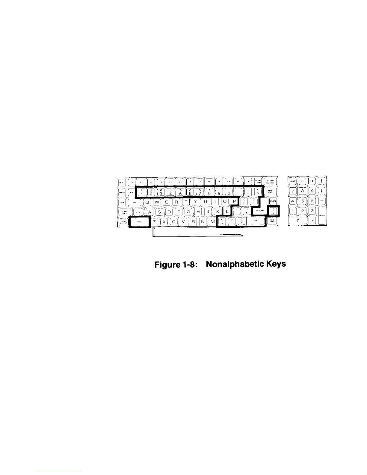
Nonalphabetic Keys
• The nonalphabetic keys are those with double markings, as shown in
Figure 1-8. These include the numbers 0 through 9, punctuation marks,
and special characters. The lower marking is generated when both of
the SHIFT keys are released, while the upper marking is generated w hen
either SHIFT key is held down. The CAPS LOCK key will not shift these
keys.
Page 28
Chapter 1 Operation Page 1-10
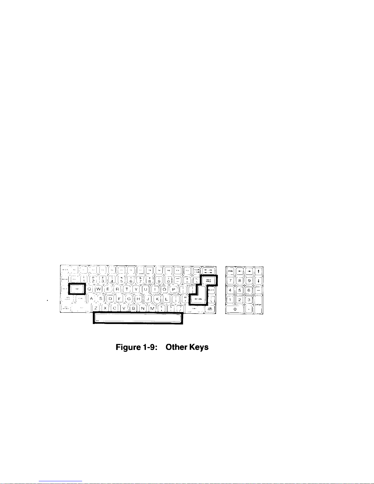
Other Keys
The following discussions describe the normal function for each key. However, software (a program) may direct any key to cause some other action to
take place. Any key that performs a special function is usually described in the
documentation that accompanies the program.
Refer to Figure 1-9 for the following discussion.
• SPACE BAR - Enters a blank character (space), just as it does on a
typewriter.
• BACK SPACE - Moves the cursor' one space to the left, just as it does on
a typewriter.
• TAB - Moves the cursor to the next tab column (set to every eighth
column).
RETURN - Returns the cursor to the left side of the display (software will
usually add a line feed as well). It also tells the computer that data or
instructions have been entered and may be processed or executed.
1
A "cursor" is an indicator on the display that lets you know where the next
key entry will appear. The indicator may be an underline or a solid block.
Page 29
Chapter 1 Operation Page 1-11
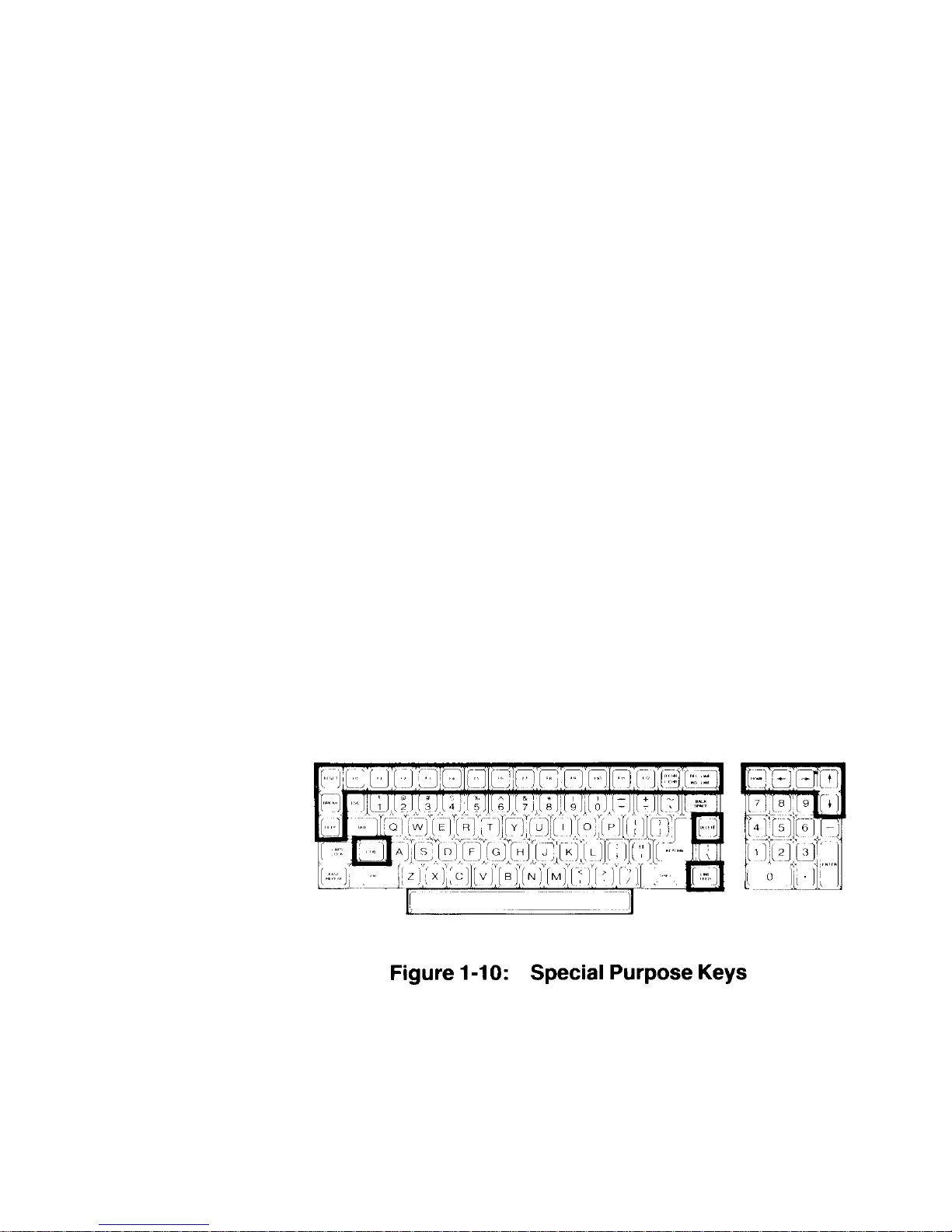
See Figure 1-10 for the next discussion.
The following keys are used for special purposes. Instructions that tell you
how to use them will appear with the prog rams.
• Special function keys (FO through F12) - Used for special purposes by
some programs.
• HO M E, L I N E F E E D, a n d a r r ow k e y s - Used to control cursor movement
and screen presentation by some programs.
• D CHR/I CHR and DEL LINE/INS LINE keys - Used in applications that
require special insertion and deletion operations.
• DELETE - Often duplicates the BACK SPACE key, but is sometimes
used for other purposes.
• BREAK - Used to interrupt program execution (not always active).
• RESET - Used w i t h the C T R L k e y ( d e s cribed later) to reset the computer
to a power-on state. This key also has a power-on indicator in it which will
be illuminated whenever the computer is turned on.
• HELP - Used by some programs to provide operator aid in the form of
special "prompts," or "helps."
Page 30
Chapter 1 Operation Page 1-12
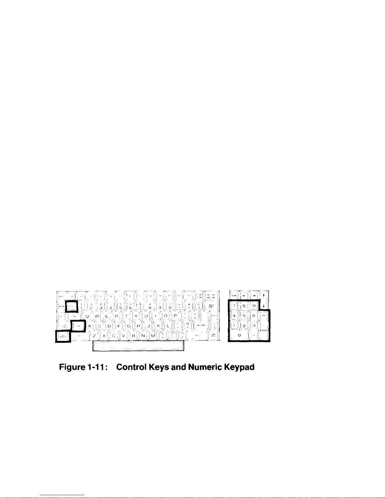
The following keys are used in combination with other keys to perform a
function. See Figure 1-11.
• ESC - The escape key. Performs special functions when you press Et and
another key in sequence. For instance, if you want to enter ESC
E, you would press the ESC key, release it, and then press the E key. If
you want to enter ESC <, you would press the ESC key, release it,
press and hold the SHIFT key, and then press the < key.
• CTRL - The control key. You can use it to perform special functio ns by
pressing it and an alphabetic key at the same time. For instance, if you
want to enter the CTRL-C combination, you would press and hold the
CTRL key and then press the C key, or you m ay press both keys a t the
same time. If you want to enter the CTRL-S combination, you would
press and hold the CTRL key and then press the S key, or you may
press both keys at the same time.
The following keys are used to speed up the entry of data.
• Calculator-style keypad - This group of keys, located to the right of the
main keyboard, is organized somewhat like a calculator and include: the
numbers 0 through 9; a period for entry of decimal points; a dash for
entry of negative numbers; and an ENTER key fo r signaling the computer
that the entry has been completed.
• FAST REPEAT - This key, when held down at the same time as
another key, triples the rate of normal repeat entry and takes effect
immediately. It is especially convenient when you want to enter the
same key a large number of times. The CTRL and SHIFT keys are not
affected by the use of this key.
Page 31

Chapter 1 Operation Page 1-13
Disk Drives
The disk drives are storage devices designed to transfer information into and
out of your computer's me mory. Refer to Figure 1-12 for the All-in -One model
and Figure 1-13 for the Low-Profile model.
NOTE: The disk drives shown in this manual are typical of the type sup-
plied in Zenith Data Systems computers. The drives in your unit
may appear to be different; however, they function the same.
• Disk drive positions - One or two disk drives are included with your
computer. For dual-drive systems on the All-in-One model, the top disk drive
is referred to as drive A and the bottom as drive B. One the Low-Profile
model, the left disk drive is drive A and the right one is drive B.
If your computer has only one disk drive, it will be known as drive A,
regardless of its position in either the Low-Profile or All-in-One mod el.
The drive names, A and B, are arbitrary with the disk operating system
(DOS). The systems supplied with your computer use these names. Other
operating systems may refer to the drives by other means. Consult the
documentation supplied with those systems for the names of the drives (drive
A will be the lowest-named drive; drive B, the next).
Page 32

Chapter 1 Operation Page 1-14
Refer to Figure 1-14 for the following discussion.
• Disk load slot - Inse rt 5.2 5-inch disks in this slot with the label up and
toward you. If the disk is not oriented as shown in the figure, the
computer will not operate properly and you may damage the disk and/or
disk drive. If the disk meets resistance while you are inserting it into
the drive, check to make sure that there is not a disk already in the
drive. It should slide smoothly into the drive.
• Disk drive latch - Your floppy disk drive may have a latch, door, or
handle as illustrated in the insets. It is used to secure the floppy disk
in the proper position in the disk drive. Closing the latch engages the
drive hub into the disk and brings the read/write heads into contact
with the disk surface. If the latch closes with difficulty, remove the
disk, inspect the edge of the center hole for damag e, check for proper
floppy disk orientation (see the previous discussion), and try again.
NOTE: Several different disk drive types are equipped with a
locking mechanism that prevents the latch from being
closed if there is no disk inserted in the drive. This
pr e v e n t s p o s s i b l e d a m a g e t o t h e r e a d /w r i t e heads. Be sure
there is a disk inserted in the disk drive before attempting to
close the latch.
• LED Disk Access Indicator - This light, which may be in one of several
different locations on the front of your disk drive, indicates that the
computer is attempting to read from or write to the disk. The read/write
operation will be successful only if the disk is inserted pr operly and the
disk drive latch is closed.
Page 33

Chapter 1 Operation Page 1-15
NOTE: Winchester disk drives do not have removable disks. Instead, all
you will see is the LED disk access indicator.
Disks
The floppy disk, or disk, sometimes called a diskette, is a precision storage
medium which requires care and attention to insure a long, trouble-free life.
A disk is made up of three parts (see Figure 1-15): the plastic disk, the disk
liner, and the disk jacket. A disk envelope is pr ovided for additional protection
when the disk is not being used in your computer.
The disk is made out of a very thin plastic material (usually Mylar®) that is
flexible and coated with a magnetic oxide similar to that used in magnetic
recording tape. It can be bent or marked easily, leaving distortions in its
surface that will destroy its usefulness.
Page 34

Chapter 1 Operation Page 1-16
The disk is well protected against accidental damage. The protective liner, a
sleeve of cloth-like material that cleans the disk and traps dust particles, is
placed around the disk. The outer jacket (with a label on the upper left-hand
corner) adds additional protection and makes the disk somewhat
protective envelope covers the exposed areas of the disk when it is not in use
or is being stored.
The outer jacket has three openings and a notch along one side. The disk
drive grips the disk through the large center opening. The small circu-lar hole
to one side is used for timing purposes. The read/write head accesses the
disk through the long slot.
The notch, on 5.25-inch disks, is called a "write-protect notch" and is located
near the label. Whenever you have important information on a disk that you
do not want to "write over," place an opaque tab over this notch. The
computer will sense its presence and will not record on this disk. I .B
disks (used in 8-inch disk drives), the notch is located near the read/write
head access slot and is a "write-enable" notch that must covered in order to
record information on the disk.
rigid. The
-
1 8-inch
The read/write head functions like the recording and playback head in a tape
recorder. The disk comes in contact with the read/write head, which will either
record (write to) or read magnetic impulses from the disk. If the d isk i s i n any
way deformed, this process is interrupted and valuable data can be lost.
For instance, the oily residue left from a fingerprint will cause the disk to
loose good contact with the head, interrupting the read/ write process.
You can compare a disk to a file cabinet that is f all of files. When the disk is
new, it is like new, empty file drawers. You have to organize ("format") the
disk so it can hold your "files" of information. This information may take the form
of data, programs, or the disk operating system (DOS). The "Disk Operating
System" chapter of this manual will tell you
how to organize, or format, your
disks.
Page 35

Chapter 1 Operation Page 1-17
Refer to Figure 1-16. A disk's surface is divided into tracks and sectors. A track
is that portion of the disk that passes under the read/write head. It is divided
into sectors by either timing holes placed in the disk itself, or by software.
When timing holes determine the sectoring of a track, the disk is said to be a
"hard-sector" disk. When software determines the sectoring, the disk is a "softsector" disk.
The amount of information each sector can hold determines the disk's d ensity.
(Disks are sold as single- or double-density types.) If a disk is capable of
"double-density" usage, it can hold twice as much information as the standard
"sing le-den sity" d isk. A d ouble- densit y disk c an be fo rmatted for single-density
use, but a single-density disk should not be formatted for double-density use.
Page 36

Chapter 1 Operation Page 1-18
The number of tracks that a disk can hold is measured in tracks per inch
(tpi). Two common specifications are 48 tpi and 96 tpi, although you may
find these disks labeled 40 tracks and 80 tracks, respectively. Occasionally,
you will find disks labeled for 35-track systems. Your computer uses 48 tpi,
40 track disks in its built-in drives. If 48 tpi disks are not available, you may
safely use 96 tpi disks.
The other difference between disks is the number of sides. All disks are
coated on both sides; however, double-sided disks have been tested for
use with double-sided disk drives. Single-sided disks are for disk drives that
only write on one side of the disk. Your computer has double-sided disk d rives
to provide full business applications usage.
When you purchase disks for use in the built-in drives of your computer, ask
for 5.25-inch disks that are soft-sectored, double-sided, and doubledensity.
You may use either 40 track, 48 tpi, or 80 track, 96 tpi disks.
For 8-inch disks, ask for double-sided, double-density 77 track, 48 tpi disks.
You may also use single-sided, single-density disks, but will have to make
special provisions when you format them.
Disk Care
Because the disks can be damaged when you handle them, keep the
following precautions in mind.
When you prepare a label for a disk, write on it before yo u place it on the
disk; or, if you must write on a label that is already on the disk, use a felttip pen. Ball point pens and pencils may exert enough force on the disk to
crease the Mylar (thus destroying its usefulness) and should not be used to
mark labels once they are on a disk.
Handle the disk much the same as you would an audio record. It should
be stored in its protective envelope in an upright position and away from
heat or direct sunlight when not in use. Don't bend it or use paper clips on it
and do not touch the exposed areas of the disk.
Page 37

Chapter 1 Operation Page 1-19
Magnets and magnetized objects can erase some of the information stored on
your disks. Also, X-rays may destroy the data on a disk. By keeping your
disks away from these sources of trouble, you can help reduce problems with
your computer.
Power Up
You are now ready to see your new computer in operation. The following
directions will help you power up your computer and prepare it for the
demonstration disk.
Turn on the power switch. You should see the power-on indicator (in the
RESET key) light and disk drive A's disk access indicator glow.
NOTE: The disk access indicator may not glow if certain features are not
enabled on your computer. However, if you do not see the poweron indicator light up, turn the power off and refer to In Case of
Difficulty in this chapter.
After about 30 seconds, the following message should appear on the
screen.
Device Error
A small hand (called the "hand prompt"), pointing to a cursor, will appear in
the upper left-hand corner of the screen. If the prompt does not appear, press
both the
hand, and cursor still do not appear after another 30 seconds, refer to In Ca se of
Difficulty at the end of this chapter.
CTRL and RESET keys at the same time. If the message, small
NOTE: If the disk access light does not glow when you turn on your com-
puter, the hand prompt should appear very shortly. If it does not,
press both the
hand prompt does not immediately appear, refer to the In Case of
Difficulty section.
Also, you may override the 30-second wait by pressing the
while the disk access light is glowing. The screen will then display the
following message and the hand prompt.
Boot Abort
CTRL and RESET keys at the same time. If the
DELETE key
Page 38

Chapter 1 Operation Page 1-20
Z-100 Demonstration Disk
Introduction
The Z-100 Demonstration Disk will show you some of the power and versatility of your new computer. The demonstration disk contains three
sections; the first two are automatic and will provide you with a good demonstration of the graphic capabilities of your computer. The third section is a
useful program that will allow you to specify, design, and display your
information using the graphic capabilities of either Z-BASIC or (3WBASIC. The instructions for using the interactive portion of the disk are found
in Appendix K.
If this is the first time that you are going to use your demonstration disk, be
sure you have read the section on disks, found earlier in this chapter, before
you start. You may also want to make a back up copy of it for safe keeping.
You will need MS-DOS to do this. Refer to Appendix L of this manual for
information about making backups.
To; use your demonstration disk, follow these procedures:
If you have not done so, turn on your computer. Otherwise, if the hand
prompt is showing, press the B key. The word Boot will appear on t he
screen. Press the F1 key. The letters f1 will appear on the screen
in reverse video (dark letters on a light background). Press the RETURN
key.
NOTE: Look at your demonstration disk. If a tab is covering the writeprotech
notch, remove it.
Refer to the Disk Drive section earlier in this chapter and insert your
demonstration disk into drive A (left drive on the Low-Profile model, top
drive on the All-in-One model).
Page 39

Chapter 1 Operation Page 1-21
After a moment, a message similar to the following will appear on the screen .
These are the sign-on messages of Z-DOS, an operating system used
on your computer.
Z-DOS/MS-DOS BIOS release 1.00, version 1.00
Z-DOS/MS-DOS release 1.00, version 1.25
(C)Copyright 1982 Zenith Data Systems
Z-DOS/MS-DOS Command release 1.00, version 1.19
The demonstration program will then automatically start and you will see the
following:
A: zbasic choice
There will be a brief pause while the next part of the program loads into
your computer's memory. The screen will clear and then display the BASIC
copyright notice (similar to the following):
Z-BASIC Rev. 1.0
[Z-DOS/MSDOS Version]
Copyright 1982 (C) by Microsoft
Created: 15-Jul-82
62168 Bytes free
Page 40

Chapter 1 Operation Page 1-22
Master Menu
The master menu will now load into memory, the screen will clear,
and the followi ng choices will be disp layed:
Z-100 / Z-BASIC Demonstration System
Version 1.0
<:F1> Artwork.
<F2> Interactive Business Graphics.
Enter your choice :
If you press the F1 function key, you will select an automatic display
of several interesting graphic designs. If you press the F2 function
key, you will select a program which will allow you to design and
di s pla y di ffe rent charts on your computer.
If you do not want either program, you may safely end the program.
To do so, open the disk drive door and remove your disk. Then
either pre ss both the CTRL and RESET keys at the same time or
turn off your computer.
Artwork
Press the F1 function key to select the artwork display. The
screen will clear and the following will be displayed.
A:autoexe1
A:zbasic f
Page 41

Chapter 1 Operation Page 1-23
After a moment, the screen will clear and the BASIC copyright notice will
appear. Then the screen will again clear and the first display will be
drawn. After it is completed, the screen will once again clear and a new
display will be drawn. This process will continue through the entire
se ri es of displays.
If you want to "freeze" any picture, press both the CTRL and S keys at
the same time and then release them. This action will stop the display and
allow you more time to study the drawing.
To continue the display, press any other key.
After all the displays have been completed, the computer will return to the
master menu where you may either reselect the artwork series or go on to the
business graphics section.
Interactive Business Graphics
The interactive business graphics portion of your demonstration disk is
actually a set of very powerful programs which you may use by themselves or
incorporate into your own software. The interactive portion of the program is
described in Appendix K at the back of this manual.
Press the F2 function key at the master menu. The screen will clear and
the following will appear on your screen:
A:autoexe1
A:zbasic menu
Page 42

Chapter 1 Operation Page 1-24
Then the BASIC copyright notice will appear, the screen will clear,
and the f o l l owing m enu illustrated in Figure 1-17 will be displayed.
In addition, the business graphics menu runs a continuing
display of various types of charts in three "windows." The
following types of charts are illustrated:
• Line charts
• Side bar charts (horizontal bars)
• Bar charts (vertical bars)
• 3-D charts (three-dimensional bars)
• Trend-line charts (data with least square fit analysis)
• Pie charts (single, full-screen pie)
• Multiple-pie charts (up to eight pies on one screen)
Page 43

Chapter 1 Operation Page 1-25
For now, select the continuous demonstrations to look at full-screen
representations of the different types of charts. Later on, after you
have become familiar with your new computer, you may turn to
Appendix J and use the other three functions of this program to
create your own charts with your own information.
Press the F4 function key to select a demonstration of screen-
sized charts. Like the artwork demonstration, this program does
not require any keyboard entries on your part.
The display is a series of designs created by Zenith Data Systems
as examples of each of the seven types of charts. In some cases,
you will see different examples that illustrate the versatility offered in
the design phase of these routines. Two types of charts will not be
illustrated on machines that do not contain the color option: multip l e
pie charts and three-dimensional bar graphs. A test is
performed and an appropriate message will be displayed for the
monochrome display machines.
Each chart will be displayed for about a minute (or 40 seconds
on 8 MHz machines) before going on to the next.
If you wish to exit the continuous demonstration portion, press
the HOME key when the following appears at the bottom-left of
your screen:
PRESS <HOME>
Otherwise, when the entire series has been displayed, the program
will return to the business graphics menu.
To return to the master menu from the business graphics menu,
press the HOME key. The screen will clear and the master
menu will be displayed. At that point, you may remove your disk
and reset your computer or turn it off.
Page 44

Chapter 1 Operation Page 1-26
In Case of Difficulty
ZDS computer hardware and software products are designed to
work together as a complete system. Proper operation can be
assumed only when your computer is used with ZDS-designed or
approved accessories. ZDS does not assume the responsibility for
improper operation resulting from custom interfacing, custom
software, or the use of accessories not approved by Zenith Data
Systems.
All the computer components have been wired and tested by ZDS.
If you encounter any malfunction during the warranty period, call
your Zenith Data Systems dealer or authorized Zenith Data Systems
repair facility to arrange for service. Do not attempt to service this
computer yourself during the warranty period; to do so may void the
warranty.
You may have out-of-warranty products repaired by your Zenith
Data Systems dealer of authorized Zenith Data Systems repair
facility. You may wish to obtain a maintenance contract for your
computer system, or you can purchase individual replacement parts
to do your own service.
If you cannot locate a Zenith Data Systems dealer or repair facility,
call 1-800-447-4700 (in Illinois, 1-800-322-4400) for the name and
location of one nearest you.
The following information will provide you with information concerning
possible solutions to common problems.
Condition: Nothing happens at power on, and the red light in
the RESET key is not lit.
Possible causes: 1. The AC power cord may not be plugged in
(check both ends). If you are using a
multiple outlet box, check its plug.
2. The power may not be on at the AC power
source (wall outlet). Check the power source
with a different electric device.
3. The computer's (or the multiple outlet box's)
power switch may not be on.
4. The line select switch may be set incorrectly
for your power source.
Page 45

Chapter 1 Operation Page 1-27
Condition: No video (blank screen).
Possible causes: 1. The brightness control may be turned
down (either in the All-in-One model or
external monitor).
2. The external monitor (Low-Profile
model) may not be plugged in and/or
turned on.
3. The external monitor (Low-Profile
model) may not be property connected
to the computer.
4. The computer may not be transmitting a
signal (screen may have been blanked
or cleared by a program). Note that this
will not be the case when you first turn
your computer system on or if the
computer is waiting for you to do
something.
5. The computer may have failed during
the initial self-tests.
Condition: Insufficient brightness on the screen.
Possible cau se : 1. The brightness control is probably turned
down (either in the All-in-One model or
external monitor).
Condition: With the autoboot feature off, the disk won't boot from
the hand prompt.
Possible causes: 1. You may not have pressed the B, F1,
and RETURN keys. Press the CTRL
and the RESET keys at the same time
and try again. Don't forg et to press the
RETURN key after pressing the B and
F1 keys.
2. You may have the wrong disk in the d isk
drive (you may be trying to boot from an
unformatted disk or a data disk).
3. The disk may be inserted in the drive
wrong or may be in the wrong disk drive.
4. The disk drive latch may not be closed.
5. You may have pressed the wrong key.
6. The disk may be damaged. Try another
bootable disk.
Page 46

Chapter 1 Operation Page 1-28
Condition: With the autoboot feature on, the system won't
boot automatically.
Possible causes: 1. You may have the wrong disk (you must use
a system disk in the boot drive).
2. The disk may be inserted in the drive
incorrectly or may be in the wrong disk drive.
3. The disk drive latch may not be closed.
4. The disk may be damaged. Try another
bootable disk.
Condition: The system resets to the power-up point or the
disk keeps rebooting.
Possible causes: 1. You may have a bad or loose power cord.
2. You may have a bad disk (part of the
information on it may not be read correctly).
This is not a common cause for this
condition - it is more likely that the system
would not boot properly from a damaged
disk.
Page 47

Chapter 1 Operation Page 1-29
Service Information
In the extreme case where you are unable to resolve a problem with
your computer system, you may want to contact your local Zenith
Data Systems dealer or authorized Zenith Data Systems service
center.
If you can isolate the problem to a particular symptom or hardware
unit, such as the printer, you will save time and possible service
expenses.
When You Call for Help
When you call for service, list the following information about your
computer and its peripherals. It will help your ZDS representative
diagnose and repair your unit.
1. The problem you are having. Supply any error messages
that may have been displayed on the screen at the time your
equipment failed.
2. The name, model number, and series or serial number of
your computer and affected peripherals.
3. The way your system is configured; that is, the name and
model numbers of the peripherals that are connected to your
computer and how (or where) they are connected.
4. Any additional information that will help describe your system
and the difficulty you are experiencing.
Page 48

Page 49

Z100 Manual Disk Operating System Page 2-1
Introduction
A disk operating system, or DOS, is a program that lets you do
certain tasks, such as organize the disk (with the FORMAT
command), copy information from one disk to another (with the
COPY command), enter the date and time (DATE and TIME
commands), and load other programs.
NOTE: Two disk operating systems that work with your computer
are MS-DOS and CP/M. There is also at least one version of
BASIC for each operating system: BASIC-80 for use with CP/M85 and existing 8-bit software, and Z-BASIC for use with MS-DOS
and 16-bit software. GW-BASIC is also available for use with MSDOS.
MS-DOS was prepared for Zenith Data Systems Z-100 Computers
by Microsoft. It is compat ible with the same MS-DOS that runs on
the IBM Personal Computer. MS-DOS stands for Microsoft Disk
Operating System. It is supplied on disk and must be loaded into
your computer.
To load MS-DOS, you will use a program called a "monitor," which
is built into your computer. The monitor program is always there,
ready to h elp yo u g et st art ed , t o c he ck o ut ce rt ai n fe at ur es , a nd
to serve as a system supervisor. You will learn how to load MSDOS into your computer and how to use some of the features of
MS-DOS to organize disks and duplicate them.
CP/M-85 is briefly compared to MS-DOS in Appendix I. Complete
information concerning this operating system is contained in the
CP/M-85 documentation.
If you are using your Z-100 computer for the first time, be sure
you have read the "Operation" chapter of this manual; it contains
important information for new users. Even if you have used other
computers, you should read the discussion on controls before you
attempt to use your computer.
NOTE: The following information assumes you have two
floppy disk drives built into your computer. If your system has only
one floppy disk dr ive, refer to Appendix D for proper use of one-drive
commands.
Page 50

Z100 Manual Disk Operating System Page 2-2
The Monitor Program
Your computer contains a special program, called a monitor, that is
designed to help you get started. One of its functions is to load (or
"boot") the disk operating system from disk into memory. The Z100 computer is set at the factory to automatically boot the DOS
when it is turned on. By setting a switch (see Appendix G) you
can di sable this f eat ure (call ed "autoboot").
Autoboot
If autoboot is disabled, after power up you will see a small hand
point ing to a flashing underline in the upper left-hand corner of the
screen. This "prompt" is the computer's way of telling you that it is
ready and waiting for your command. To execute any monitor
program command, the hand prompt must be present. It occurs
automatically after the system is turned on and may be restored at
any time. To do so, simultaneously press both the CTRL and
RESET keys if you ev er find that you need to start over. However,
do not reset your computer unless you are sure that no important
programs are being executed.
If autoboot is enabled (set as the computer comes from the
factor y), then there will be no display until a certain amount of time
passes, or you press the DELETE key, or you insert a disk with
the DOS on it into drive A:
If you press the DELETE key, the autoboot process will be
interrupted and the screen will show:
Boot Abort
and the hand prompt. The system is now in a manual mode and
you can use the commands described later in this chapter.
If you wait for the system and do not put a disk into drive A, the
screen wiIl show:
Device Error
Page 51

Z100 Manual Disk Operating System Page 2-3
and the hand prompt. This message will also appear if you put the
disk into the disk drive incorrectly.
The system is now in a manual mode and you can use the
commands described later in this chapter.
If you want to restart the computer at any time, press both the CTRL
and RESET keys at the same time. The computer will attempt to
boot in a DOS, as it did when you first turned it on. If you have a
disk properly inserted in drive A, the DOS will be booted.
The Commands
The monitor program will execute twelve different commands, a
summary of which is shown in Table 2-1. Only a few are explained
here. The remainder are briefly described in Appendix C.
Tabl e 2- 1 : Monitor Command Summary
COMMAND NAME DESCRIPTION
B Boot Loads the operating system from a disk.
C Color Bar Displays a color bar pattern on the screen. If the
comp uter does not have color capabilit y, a single white
bar, will be displayed on the right half of the screen.
Monochrome displays will display a pattern of gray-scale
bars.
D Dump Displays the contents of a block or portion of memory in
hexadecimal and ASCII.
E Examin e Examines and/or changes the contents of a memory loca-
tion.
F Fill Fills the specified range of memory locations with the
data entered.
H Help Displays the list of monitor program commands.
HELP k e y Help See the H command.
I Input Returns the contents of the specified port.
O Output Sends a value to the specified port.
S System Displays the parameters (memory size, video RAM
devices, video type: color or monochrome) of the
computer.
T Test Displays the diagnostic test menu.
V Version Displays the version number of the ROM program.
X Execute Initiates machine language program execution at the
specified memory address. Allows breakpoints.
Page 52

Z100 Manual Disk Operating System Page 2-4
Some of these commands are used by programmers for machine
language Programming and debugging (see later discussion on
programs in Chapter 3).
B – Boot
This is the monitor command you will use if your system is not set
up to boot automatically, if a disk is not autobooted after power
up , or if you want to manually boot the system. The boot process
reads the operating system from the disk and loads it into the
computer. To use this command
Make sure the computer is on and the hand prompt is showing.
Insert the MS-DOS disk (or any disk that contains a Z-100 disk
operating system) into drive A (see the discussion on disk
drives in Chapter 1).
Close the disk drive door or latch.
Press the B key and then the F1 function key. The computer
will display:
Boot f1
Press the RETURN key.
The computer will now execute the boot routine and load the
operating system from the disk in drive A into the computer's
memory.
There are several variations of the boot command available to you.
Three of the function keys, F1, F2, and F3, tell the computer what
kind of disk drive to use: F1 is for the built-in floppy disk drives,
F2 is for the optional 8-inch floppy disk drives, and F3 is for the
optional Winchester disk system.
In addition to being able to specify which disk drive type, you may
also specify which disk drive by using the number keys: 0 for the
first drive (drive A, if you are booting from the built-in floppy disk
drives) and 1 for the second disk drive.
Page 53

Z100 Manual Disk Operating System Page 2-5
Therefore, if you want to boot from the second 8-inch floppy disk
drive, you would (1) turn on your computer and the 8-inch disk
system, (2) insert an 8-inch floppy disk into the bottom 8-inch disk
drive (it must contain a Z-100 operating system), (3) close the drive,
and (4) press the B key, the F2 key, the 1 key, and the RETURN
key, in that order. The computer will display:
Boot f21
and load the operating system from the second 8-inch disk drive.
NOTE: For a complete discussion on the optional 8-inch disk
drives or Winchester disk system, refer to the
documentation that accompanies these product s and also
your operating system documentation.
C - Color Bar
If your computer is equipped with color video memory, it has the
capability to display a color bar pattern on the screen so you may
adjust your color monitor for the most pleasing display. To use this
command:
Make sure your computer is properly attached to your color
monitor.
Make sure the monitor is on.
Make sure the computer is on and the hand prompt is showing.
Press the C key. You will see one of two possible patterns,
depending upon the capabilities of your system.
• If your computer is equipped with color video memory, you
will see a pattern of color bars across the top half of
the screen. Each color bar will be identified with the
name of the color that is being represented. On a
monochrome monitor, the pattern will be shaded from the
most dark to the mos t light, left-to-right.
Page 54

Z100 Manual Disk Operating System Page 2-6
• If your computer is not equipped with color video memory,
you will see a single block of light in the upper right-hand
quarter of your display.
Use this pattern to adjust the controls for your monitor to provide
the most pleasing display.
H -- Help
This command will display the commands available for the monitor
program. The HELP key, located on the left side of the keyboard
will also provide the sam e display when it is pressed. To use this
command:
Make sure the computer is on and the hand prompt is showing.
Press either the H key or the HELP key. The computer will
display:
Boot
Color Bar
Dump
Examine
Fill
Help
<HELP Key>
Input
Output
System
Test
Version
Xecute
A complete description of each command is found in Appendix C.
Page 55

Z100 Manual Disk Operating System Page 2-7
S - System
This command will provide you will a brief summary of the features
of your computer. If provides you with the amount of system memory
installed in your computer, the amount of video memory installed in
your computer, and the type of video (color or monochrome)
supported by your system. To use this command:
Make sure the computer is on and the hand prompt is showing.
Press the S key. The computer will show you a display similar to:
256Kb of contiguous RAM
64Kb Video memory
Color
This particular display tells you that your system has 256 kilobytes
of random access memory (RAM) and 64 kilobytes of color video
memory. Other variations that will commonly be seen are 128 or
192 kilobytes of random access memory and 32 or 64 kilobytes of
color or monochrome video memory.
V - Version
NOTE: Professional software is released in version s. Updates and
enhancements to these programs are made as they are
developed. Each time a revision of this type occurs, it is called a
new "version" and given a number (Version 1.0, Version 1.1,
Version 2.0, etc.).
You can use the Version command whenever you want to find out
what version of the monitor program you have in your computer. To
use this command:
Make sure the computer is on and the hand prompt is showing.
Page 56

Z100 Manual Disk Operating System Page 2-8
Press the V key. The computer will display:
Version 2.5
and return to the hand prompt.
The display tells you that the monitor version (in this example) is
2.5. There is no relationship between the monitor version
number and the operating system version number shown later in
this chapter.
Loading MS-DOS
With the MS-DOS manual, you will receive two MS-DOS disks:
disk #1 and disk #2. The following steps will show you how to
"load" the disk operating system the first time and then create
"backups," or "working copies," of the distribution disks.
To load MS-DOS:
Turn on the computer or press the CTRL and RESET
keys at the same time if the computer is already on.
Insert the MS-DOS distribution disk #1 into drive A.
Close the disk drive door or latch.
If you are booting the computer manually, press the B key and
then the F1 key. The computer will display the following.
Boot f1
Press the RETURN key.
Page 57

Z100 Manual Disk Operating System Page 2-9
The floppy disk drive's disk access indicator will come on,
indicating that the disk is being "read" by the computer. You
ma y h ear a fa int wh irr ing noise, which is the normal sound of the
disk drive motors.
As MS-DOS is read into the computer, your display will show a
message similar to:
MS-DOS Version 2.20
Copyright(C) 1984, Zenith Data Systems Corporation
A>date
Current date is Mon 11-12-1984
Enter new date:
The date actually shown on your computer will probably differ
from this sample. The format for entering the date is M/D/Y or
M-D-Y where M is the month (1 to 12), D is the day (1 to
31), and Y is the year (80 to 99). Four digits may be used
for year if you are enterin g a year from 2000 from 2099. Any
other response will cause the computer to display:
Invalid date
Enter new date:
Some examples of how valid dates are entered and stored are:
Your entry: Will be stored as:
6-9-82 Wed 6-09-1982
12-31-2084 Sun 12-31-2084
8/12/91 Mon 8-12-1991
2-5-85 Tue 2-05-1985
Enter the current date and press the RETURN key. The
computer will display:
A>time
Current time is 12:02:17.16
Enter new time:
Page 58

Z100 Manual Disk Operating System Page 2-10
The time actually shown on your computer will probably differ from
this sample. You will use the format H:M:S.C to enter the time,
where H is hours (0 to 23), M is minutes (0 to 59), S is second (0 to
59), and C is tenths of a second (0 to 9). Minutes, seconds, and
tenths of a second are optional and may be omitted. The
separators, colon and period, must be used exactly as shown or
else the
Some examples of valid entries and how they are stored in your
computer follow:
following error message will be displayed.
Invalid time
Ente r new time:
Your entry: Will be stored as:
9:15 9:15:00.00
9:15:30 9: 15: 30.00
9:15:30.5 9:15:30.50
14:2:3 14:02:03.00
Enter the current time and press the RETURN key. The
display will now show:
'Path- \bin
You have now successfully loaded MS-DOS into your computer.
The computer has performed one other function: to allow you to
access all the programs on the default disk without having to worry
about "directory paths." Directory paths will be explained later in this
chapter.
Page 59

Z100 Manual Disk Operating System Page 2-11
The MS-DOS Prompt
Normally, after you load MS-DOS, you will see:
A>
You can see by this example that the small hand has been replaced
by the A>, which is MS-DOS's prompt. The A> also tells you
whi ch dr ive is currently being used by the system. This is called
the "default drive." Later on, you'll find out how to change the
drive being used. But first, you need to create a copy, or backup,
of MS-DOS and store the original in a safe place.
Making A Backup
Backups
A backup might easily be considered to be an "insurance copy." It is
a duplicate of important data. During the course of normal
operation, accidents do happen and a disk can be accidentally
ruined. By having a backup, you have "insured" yourself against t he
loss of information that may be vital to the successful operation of
your business or computer.
By making backups at regular intervals, you can minimize the
amount of work that would be necessary to bring your computer
records up to date if information is lost through mishandling of a
disk or by some other cause.
Backups also provide a convenient method of rotating your disks
so t h a t one is not in constant use. The backup procedure gives you
a way of verifying that the disk you are using is a good one, an d not
one which may cause a problem.
Since you computer has now loaded MS-DOS and is waiting for
your instructions, the following will take your through the step-bystep process. Appendix L illustrates another method you can use to
make a backup of important disks while using MS-DOS.
Page 60

Z100 Manual Disk Operating System Page 2-12
Backing Up Your Disks the First Time
The DISKCOPY utility has been designed to allow you to create an
exact duplicate, or backup, of a disk. You will use it now to
duplicate the two 5.25-inch MS-DOS distribution disks.
The working master disks are those that you will create during this
backup procedure. Because there is more than one disk, y ou will
be asked to repeat the process twice. The disk that is now in drive
A should be labeled disk #1. You will be given an opportunity to
make sure that it is the correct disk in a moment.
You will be copying the information from the distribution, or "source,"
disks onto "destination" disks.
To start the backup procedure, make sure that the A> MS-DOS
prompt is showing on the screen. If it is not, reboot your system
(see the procedure earlier in this chapter).
Enter the following into your keyboard. The characters you
type will be shown on t he scre en.
BACKUP/V
Press the RETURN key. The light in drive A will come on and
your screen will show a display similar to the following.
DISKCOPY version 2.20
Copyright(C) 1984 Zenith Data Systems Corporation
Source drive name? (A-H) _:
You will notice that the cursor is to the left of the colon. It is
prompting you to enter the name of the disk drive in which the
source disk is located. Now y ou can check to make sure that
you have the distribution disk, disk #1, in drive A. To do so,
open the drive door or latc h and remove the disk. After you
have checked the label on the disk and made sure it is disk #1,
put it back in drive A and close the door or latch.
Page 61

Z100 Manual Disk Operating System Page 2-13
Press the A key. The computer will now show:
Destination drive name (A-H) _:
NOTE: This backup procedure does not check to see if your
destination disk has data on it. Any information previously
recorded on the disk will be erased and blank (empty)
tracks will be placed on the disk, making it ready to
receive new data. Be sure you are using a blank disk
(or one that you wish to erase).
Insert a blank disk in drive B and close the door or latch.
Press the B key. The computer will display:
Place the source disk in A and the destination disk in B.
Press RETURN when ready.
You now have one last chance to check that you have the correct
disks in the proper drives. The source disk, MS-DOS distribution
disk #1, should be in drive A. The destination disk, a blank disk,
should be in drive B. If you are not sure that they are correct,
check them now.
You also may stop the duplication process now if you wish. To stop
(or abort) the backup procedure, you would press both the CTRL
and C keys at the same time. The computer would end the
program and display ↑C on the screen, followed by the MS-DOS
prompt. However, you need to make working copies of your
distribution disks, so continue with the following procedure.
With MS-DOS distr ibution disk #1 in drive A and a blank disk in
drive B, press the RETURN key. The light in drive A will come
on momentarily and then the light in drive B will come on.
You will see the follow ing on t he scre en.
When the light came on for drive A, the computer was checking
the type of disk in drive A and the way the tr acks were organized on
the source disk. Next, it checked the type of disk in drive B. When
it was satisfied that the disks were of an id entical
Formatting destination...
Page 62

Z100 Manual Disk Operating System Page 2-14
type (both soft-sectored, in this case), it displayed the message
and began formatting, or organizing, the tracks and sectors so
they matched those of the disk in drive A. After the destination has
been formatted, the display will show:
Copying...
Now you will see the disk access indicators in drive A and dr ive B
alternately come on. While the indicator in drive A is on, the
computer is reading infor mation fr om the disk into memory. Then
while the indicator in drive B is on, the computer is writing that
same information onto the tracks and sectors in drive B. When this
process has been completed, the computer will show:
Verifying...
Again, the disk access indicators in drive A and drive B will
alternately come on. This time, the computer reads the information
from each respective disk and then compares the data to make
sure it matches. This process verifies that the destination disk is
an exact copy of the source disk. When this process has been
completed, the computer will show:
Do you wish to copy another disk (Y/N)? <N>
Remove MS-DOS distribution disk #1 from drive A and place it
in its protective envelope.
Remove the disk in drive B and prepare a label for it. Whenever
a new disk has been used for a backup, you will want to prepare
a label for it.
Labeling Disks
There are many different methods of labeling and keeping track of
disks. One method is to keep a log containing the date the
di sk w as f ir st f or ma tted and the material that you expect to place
on the disk (a summary or title only). An example would be:
Formatted 7-15-85 PAY ROLL DATA
Page 63

Z100 Manual Disk Operating System Page 2-15
Most people assign each disk a unique number or code. This allows
them to track the location of the disk easily and use a permanent
storage area or container for the disk.
For your new copy of the MS-DOS distributi on disk #1, assign it
number 1, label it with the format date (the current date), and call
it "MS-DOS disk 1 - working copy 1." It is called a working c opy
because it is one you will use on a continuing basis. Place
the label in the upper right-hand corner of the disk, making sure
you do not cover the write-protect notch.
The message on the computer is asking you if you want to
duplicate, or back up, another disk. You need to make a
backup of the second distribution disk, so press the Y key and
then the RETURN key. The computer will show:
Source drive name? (A-H) _:
Press the A key. The computer will show:
Destination drive name? (A-H) _:
Press the B key. The computer will show:
Place the source disk in A and the destination disk in B.
Press RETURN when ready.
Insert the second distribution disk, disk #2, into drive A and
close the door or latch.
Insert a blank disk into drive B and close the door or latch.
Press the RETURN key. The computer will repeat the backup
process as described earlier in this chapter. When the
destination disk has been formatted and the information copied
from the disk in drive A and verified, the computer will display:
Do you wish to copy another disk (Y/N)? <N>
Page 64

Z100 Manual Disk Operating System Page 2-16
The letter N inside the angle brackets is the default answer that will
be accepted by the computer if you press only the RETURN key.
Since you have no more disks to copy at this time, press the
RETURN key. The computer will display the MS-DOS prompt.
Remove the distribution disk from drive A and place it in its
protective envelope.
Remove the disk from drive B and place it in its protective
envelope.
Prepare a label for the destination disk which includes the
number (number 2), the format (current) date, and "MS-DOS
disk #2 - working copy 1." Place the label in the upper right-hand
corner of the disk, making sure you do not cover the writeprotect notch with the label.
You have now completed the first backup of the distribution disks.
When convenient, you will want to make at least one more working
copy of these disks. The easiest way to do it is to follow these
same instructions. However, label your disks as copy 2 (or 3)
instead of copy 1.
It is possible that, after reading the remainder of this chapter, you
will want to make a custom working copy of MS-DOS. The
procedure in Appendix L explains how to do this.
MS-DOS Control Key Functions
The following keys and key combinations are those that function
while you are operating under MS-DOS. (If you have trouble
locating any of these keys, you will find them highlighted in the
Keyboard section of Chapter 1.)
These are the only keys, other than commands and special
function keys, tha t MS-D OS w i l l
are explained in the MS-DOS documentation.
recognize. The special function keys
Page 65

Z100 Manual Disk Operating System Page 2-17
Three single keystrokes are recognized by MS-DOS:
• RETURN - When you press this key, the computer will
accept what you have entered through the keyboard. If you
typed the information correctly, the computer will follow your
instructions.
• BACK SPACE - I f yo u acci dent ally pres s the w rong key o r
key s, y ou can use the BACK SPACE key to back over and
erase those characters. Then you can enter the correct
information.
• LINE FEED - You will not need to use this key unless you
have a large amount of information to enter on one line. MSDOS won't automatically go t o the next line when you come
to the end of the physical line on the screen and have more
information to enter. To go to the next line, press the LINE
FEED key. It will put the cursor (underline) at the b eg in ni ng
of the next physical line and then, when the command is
executed, the computer will use information from both lines.
NOTE: There is a danger in using the BACK SPACE key after
using the LINE FEED key. The BACK SPACE key will function
normally, "backing out" each character and erasing it from the
screen until it reaches the beginning of the line. Then, if you
continue to press the BACK SPACE key, it wi ll co nt i nue to back out
each character typed in the previous line, but it will not affect the
display. Without seeing the action of the BACK SPACE key, it is
difficult to know what has been backed out unless you are very
careful. The CTRL-X combination, described later, provides the
easiest solution: it cancels the current command and gives you the
opportunity to start over.
MS-DOS will also recognize the following five combinations of
keys. One key is always the control key (labeled CTRL). In this
manual, whenever you see the word "control" or "CTRL" followed by
a das h and some lette r, you are to press and hold the CTRL key and
then press the other key.
• CTRL-X - If you have entered a line of instructions and want
to start over, you have two choices. You may either use the
BACK SPACE key and back out all of the instructions, or you
may use the CTRL-X combination. This will put a back
slash (\) on the screen and start a new line. The
information you had previously entered will be ignored by
the computer.
Page 66

Z100 Manual Disk Operating System Page 2-18
• CTRL-S - Some of the commands you will give the computer
will cause more information to be displayed than the screen
vertically can hold at one time. In order to stop the
information from moving off the display, you can press the
CTRL-S combination, which will tell the computer to stop
what it is doing. Then, when you press any key, the computer will continue. By alternately pressing the CTRL-S and
another key, you can control the way information is displayed
on the screen.
• CTRL-C - There will be times when you wish to interrupt an
operation and you don't want it to finish. You can cancel
most operations by pressing the CTRL-C combination.
This tells the computer to stop what it is doing, return to
the MS-DOS prompt, and wait for your next instruction.
Remember, you have canceled the operation, so you
cannot start where you have left off - the CTRL-S allows for
that. A ^ C will be displayed on the screen where you
entered the command.
• CTRL-P - There will be times when you want to send
information normally shown on the display to a printer (if
you have one connected to your computer). By pressing the
CTRL-P combination, you tell the computer to send
information to both the computer screen and the printer.
Whenever the computer does this, most operations are
slowed, because a printer is slower than the screen.
NOTE: If you do not have a print er connected, or if it is not turned
on, or if it is off line, out of paper, or something is not right,
then the computer can "hang up" until the problem is
corrected. If there is no printer, or if there is some other
problem that cannot be easily corrected (for instance, MSDOS may not be configured for your printer), the computer
will have to be reset.
Since all printers are not alike, MS-DOS must be configur ed to the
needs of your printer. The MS-DOS command, CONFIGUR, and
how to configure MS-DOS for the needs of your printer are
explained in Appendix F.
Page 67

Z100 Manual Disk Operating System Page 2-19
• CTRL-N - This combination will cancel the CTRL-P
operation and return the computer to normal operation.
NOTE: If the printer should hang up your computer for some
reason, CTRL-N will not operate. The computer must be
reset or the fault corrected.
Try the functions described in this section. The more you use them,
the easier they will be to remember.
MS-DOS Commands
An M S- DO S command is an instruction to your comput er that you
type on the keyboard. Some of the commands, called "internal
commands," are an integral part of the operating system. Other
commands, referred to as "external commands," are actually
separate programs on the disk, and must be loaded into the
computer before the fu nctions are performed.
The DISKCOPY command, for example, is external; that is, it is a
separate prog r am . T h e C OP Y co mm a nd is i nt er n al an d , a s s u ch ,
is alw a ys a p ar t of MS-DOS. In order to use an ext ernal command,
the command "file" must exist on the disk. If it is not present, the
command will not work.
Changing MS-DOS Prompts
The prompt is a signal to you that your computer is ready to accept
a command. While using MS-DOS, you will see the prompt
displayed as the letter representing the drive being used by MSDOS (the default drive). It is followed by some symbol, usually the
great er-th an s ign ( > ) , and the cursor.
If you selected drive A (and this is the normal default drive on
power up), the MS-DOS prompt would look like this:
A>
Page 68

Z100 Manual Disk Operating System Page 2-20
If you selected drive B, then the MS-DOS prompt would appear as:
B>
The greater-than sign may be replaced by another symbol, if
desired. For more information on changing the prompt
symbol, consult your MS-DOS documentation.
You can change the prompt (and the default drive) by typing the
new drive name, a colon, and pressing the RETURN key. (You will
be instructed to use the RETURN key only in the next two
examp l es. However, y o u should always use it whenever you finish
entering an MS-DOS command.)
If drive A is currently the default drive and you want to change
the default dr ive to d riv e B, typ e:
B:
and press the RETURN key.
If drive B is the current default drive and you want to change
th e defaul t drive to drive A, type:
A:
and press the RETURN key.
You will notice that the current default drive (in the form of the
prompt) is displayed each time you finish an MS-D OS comma nd .
Error Messages
Your computer will display an error message when something is
wrong. The message itself often will tell you what is wrong so
you wil l be abl e to correct the problem . An example of this would
be:
Invalid drive specification
This message implies that, in your command, you specified a drive
that is not connected to your computer. You would then re-enter t he
command, specifying the correct drive.
Page 69

Z100 Manual Disk Operating System Page 2-21
For a complete list of MS-DOS error messages and their
m e a n ings , ref er to the M S-DOS documentation.
Files, Programs, and File Names
A file may contain either data or a program. Some "programs" may
actually consist of several different files. MS-DOS is a good
example; there are three programs (files) critical to the
operation of MS-DOS: IO.SYS, MSDOS.SYS, and
COMMAND.COM (the first two are "hidden" files - files that are
physically present on the disk, but do not display as part of the disk
directory). On the disk, these are separate files.
Each file is identified by a file "specification." It has three parts: an
optional drive name, a file name, and an extension.
• Drive name - The drive name is a letter from A to H and must be
followed by a colon. The use of these letters is limited to the
configuration of your computer system. For instance, if your
computer system does not have more than two drives and you
try to use any drive name beyond B, an error message may be
displayed.
• File name - The file name is from one to eight characters in
length. These characters can be any letter from A to Z, any
number from 0 to 9, or certain punctuation characters. Examples
of legal file names are MYFILE, Al PROG, and 333-1.
• The extension is from one to three characters in length. The
allowed characters are the same as those that you can use for
the file name. A period (.) must be used to separate the
extension from the file name. E xa mpl es ar e: B AS, S YS, a nd
COM. Some extensions, like SYS, are reserved for certain file
types. Consult your MS-DOS documentation for more
information.
Examples of valid and invalid file names are as follows.
Valid file names: Invalid file names:
MYPROG.BAS WE,3.BAS (comma)
COMMAND.COM B:MYP:2.BAS (second colon)
MS-DOS.SYS MS.OS.SYS (first period)
Page 70

Z100 Manual Disk Operating System Page 2-22
Internal Commands
The commands that are internal to MS-DOS are listed in Table 2-2.
Tab l e 2-2: Inte rnal MS-DOS Commands
THE COMMAND: TELLS THE COMPUTER TO:
filenam e.BAT Execute a file with a.BAT extension.
BR EAK [ ON|OF F] Enable or disable detection of CTRL-C.
CD Display or change the current directory (same as CHDIR).
CHDIR Display or change the current directory (same as CD).
CLS Clear the display.
COPY Copy files.
CTTY Change the device from which commands are received.
DATE Display the current system date and prompt for a new entry.
DEL Delete a file or files from the disk (same as ERASE).
DIR List directory entries.
ECHO [ON|OFF] Enable or disable the echo feature or display a message.
ERASE Delete a file or files from the disk (same as DEL).
EXIT Exit current com mand a nd ret urn t o lower comm and level .
F OR Extend batch (or interactive) command.
GOTO Branch to another command.
IF Allow conditional execution.
MD Create a new directory (same as MKDIR).
MKDIR Create a new directory (same as MD).
PA TH Search directories specified for commands/files.
PAUSE Temporarily halt batch execution.
PROMPT Use a new system prompt.
RD Remove a directory (same as RMDIR).
REM . Insert a comment in a batch file.
RE N Rename a file (same a s RENA ME ).
RENAME Rename a file (same as REN).
RMDIR Remove a directory (same as RD).
SET Set one string value to be equivalent to anothe r value.
SHIFT Make it possible to use over 10 batch param eters.
TIME Display the current system time and prompt for a new entry.
TYPE Display the contents of a file.
VER Display the current version of MSDOS .SYS and IO .SYS .
VERIFY Enable or disable verification of data after it is written to the
disk.
VOL Display the label of the disk in the default drive.
The batch processing commands, (.BAT), ECHO, FOR, GOTO, IF,
PAUSE, REM, SET, and SHIFT, will not be discussed in this
manual. Likewise, BREAK, CTTY, EXIT, PATH, and PROMPT will
not be discussed. For more information on batch files and these
commands, refer to the MS-DOS documentation.
COPY
The COPY command allows you to produce a "copy" of any file or
program . T he general form of the command is:
COPY (from) file specification (to) file specification
Page 71

Z100 Manual Disk Operating System Page 2-23
Remember that the file specificat ion is made up of the drive name,
the file name, and the extension. If the default drive is being
us ed, you may omit the drive name.
Here are some examples of the COPY command:
(1) COPY OLDFILE.EXT=NEWFILE.EXT
(2) COPY A: OLDFILE.EXT=NEWFILE.EXT
(3) COPY B: OLDFILE.EXT=A: NEWFILE.EXT
(4) COPY A: OLDFILE.EXT=B: NEWFILE.EXT
In each case, the file OLDFILE.EXT was duplicated under the
name of NEWFILE.EXT. The drive names allow you to: (1) use the
default drive for both files; (2) use drive A as the s ource drive and
the default drive for the destination; (3) use drive B as the source
drive and drive A as the destination; and (4) use drive A as the
source drive and drive B as the destination. You will note that, in
examples (3) and (4), the default drive was not important.
Wild cards (see the discussion under the DIR command) give you
flexibility and allow you to back up a disk without having to know the
names of each fi le. The backup copy procedure in Appendix L
uses asterisks in :his manner.
There are several options and limitations in the format of the COPY
command. These are fully explained in the MS-DOS documentation.
However, me very important restriction (for your protection against
accidental file destruction) is that you may not copy a file onto
it s el f . If y o u t r y it, th e following error message will be displayed.
File cannot be copied onto itself
0 File(s) copied
Page 72

Z100 Manual Disk Operating System Page 2-24
DATE
The DATE command allows you to change the date that is currently
stored in your computer. The command will be executed when
you enter DATE and press the RETURN key. The computer will
display the current date and prompt you for a new entry. If you
press the RETURN k ey without enter ing a new date, the computer
will not make any change to the current dat e.
The format for entering the date is M/D/Y or M-D-Y where M is
th e month (1 to 12), D is the day (1 to 31), and Y is the year (80 to
99). Four digits may be used for year if you are entering a year
from 2000 from 2099. Any other response will cause the computer
to display:
Invalid date
Enter new date:
Some examples of how valid dates are entered and stored are:
Your entry: Will be stored as:
6-9-82 Wed 6-09-1982
12-31-2084 Sun 12-31-2084
8/12/91 Mon 8-12-1991
2-5-85 Tue 2-05-1985
Each disk, when it has been formatted, is organized to accept
files. The names of these files are stored on the disk in areas
called directories. The DIR command allows you to look at the
directories that are on the disk in t he default drive. For the following
examples, place one of your copies of MS-DOS disk #1 in drive A.
To display, or "get" the directory, type:
DIR
(Don’t forget to press the RETURN key.) You will see a listing
similar to the following on your display.
Page 73

Z100 Manual Disk Operating System Page 2-25
Volume in drive A is 890-434-09
Directory of A:\
COMMAND COM 16421 11-12-84 11:03a
ALTCHAR SYS 432 4-04-84 3:18p
AUTOEXEC BAT 23 4-04-84 2:36p
CONFIG SYS 12 9-06-84 2:36p
BIN <DIR> 11-12-84 12:02p
5 File(s) 34816 byte s free
The five columns of information represent, in order, the name of
each file, the extension name, the number of bytes used to store the
file (a byte is a measure of memory which can be equated to one
keystroke of a printable character on the keyboard), and the date
and time that file was created, last edited, or changed.
The last entry in the listing tells you that there is another directory,
indicated by <DIR>, on this disk. You will be told how to change
directories later in this chapter.
The last line on the screen shows you the number of files
displayed and the number o f unus e d byte s on the d isk.
You can list the directory of a drive other than the default drive
by adding the drive name. Place one of your copies of MS-DOS
disk #2 in drive B and then enter:
DIR B:
The computer will display on following on the screen.
Volume in drive B is 890-435-02
Directory of B:\
DEVEL <DIR> 8-20-84 10:14a
PSC <DIR> 8-20-84 10:14a
DEV <DIR> 8-20-84 10:14a
CHR <DIR> 8-20-84 10:14a
4 File(s) 214016 bytes free
In this case, there are four additional directories on the disk in drive B.
Page 74

Z100 Manual Disk Operating System Page 2-26
If you want to look for a specific file, you may use the name of the
file, as in the following examples:
DIR ALTCHAR.SYS
or
DIR B: FORMAT.COM
Note that you must use the entire file name, although the
extension is optional. The inclusion of the drive name tells the
computer to look on the disk in that disk drive.
If you attempted to use these examples, you will note that the
seco nd example, DIR B:
the following.
Volume in drive B is 890-435-02
Directory of B:\
FORMAT.COM resulted in a display similar to
File not found
This display tells you that the directory is either empty or does not
contain the file(s) for which you are searching.
Wild Cards
There are two additional characters that you may use with a file's
name. They are called "wild cards," which mean "anything," and
are represented by the question mark (?) and the asterisk (*). Wild
cards a llow you to have the computer look for a number of files that
have similar names.
You can use the question mark as a wild card to take the
plac e of any fetter in a file name. For instance, if you enter the
following command, the computer will display any files (which
appear in the directory of the disk in the default drive) with five
letter names that begin with AB, end with DE, and have the
extension of EXT.
DIR AB?DE.EXT
Page 75

Z100 Manual Disk Operating System Page 2-27
The other wild card is the asterisk (*). This character is used in
place of multiple question marks, and it can take the place of more
than one character in a file name. For instance, if you entered the
following command, the computer will display any files with names
that begin with AB and have the extension of EXT.
DIR AB*.EXT
Likewise, the following command will cause the computer to list all
files starting with the letter F, regardless of the r est of the filename or
extension.
F*.*
With MS-DOS disk #1 in drive A, ente r the following comm and .
DIR C*.*
The computer will display a directory similar to the following:
Volume in drive A is 890-434-09 Directory of A:\
COMMAND COM 16421 11-12-84 11:03a
CONFIG SYS 12 9-16-84 2:36p
2 File(s) 34816 bytes free
Multiple Directories
MS-DOS version 2 can support directory roots and branches.
Whil e th is feature is not overly important on 5.25-inch floppy disks,
it is a benefit to the operation and organization of higher-capacity
mass storage devices, such as 8-inch floppy disks and Winchester
disk systems. The following discussion briefly describes this
capability. For complete information on all of the directory
commands (CD, CHDIR, DIR, MD, MKDIR, PATH, RD, and
RMDIR), refer to the MS-DOS do cumen tation.
The concept of directories in MS-DOS version 2 is based on the
concept of a tree, where the root of the tree is the foundation that
supports the trunk and branches of that
Page 76

Z100 Manual Disk Operating System Page 2-28
tree. Likewise, the basic directory is referred to as the root directory
that supports branch directories. These branch directories are
treated as files which in turn support other branch directories and/or
the actual data and program files on the disk. In other words, an y
directory, whether it is a root or branch directory, can support
branch directories, data files, and programs.
In the case of your two distribution disks, disk #1 contains one
additional directory file, identified in the directory as BIN, while dis k
#2 supports four additional directory files, identified as
DEVEL, PSC, DEV, and CHR. In addition, the root directory of disk
#1 supports four files, COMMAND.COM, ALTCHAR.SYS,
AUTOEXEC.BAT, and CONFIG.SYS.
At this point in the discussion, you should have your computer
turned on. P lace y our w orking copi es of t he two MS-DO S disk s
in driv e A (disk #1) and B (disk #2). The default disk drive should be
drive A.
Get the directory of drive A by entering the following.
DIR
Note that because the default drive is drive A, you did not have to
specify the drive name in the command line you just entered. The
computer should display something similar to the following.
Volume in drive A is 890-434-09
Directory of A:\
COMMAND COM 16421 11-12-84 11:03a
ALTCHAR SYS 432 4-04-84 3:18p
AUTOEXEC BAT 23 4-04-84 2:36p
CONFIG SYS 12 9-06-84 2:36p
BIN <DIR> 11-12-84 12:02p
5 File(s) 34816 bytes free
The command to change directories is CD or CHDIR, followed by
the directory name (in this case, BIN). Enter the following
command, which will change the directory in drive A.
CD BIN
Page 77

Z100 Manual Disk Operating System Page 2-29
Now get the directory of drive A by entering the following.
DIR
Note that you did not use any special commands in the directory
command line. You had changed directories with the CD
command. The computer will display a directory similar to the
following.
Volume in drive A is 890-434-09
Directory o f A: \bin
<DIR> 11-12-84 12:02p
<DIR> 11-12-84 12:02p
EDLIN COM 8080 4-04-84 1:48p
CHKDSK COM 6468 4-04-84 1:47p
SYS COM 922 4-04-84 1:49p
FORMAT COM 13674 11-12-84 11:42a
CONFIGUR COM 12031 11-12-84 11:47a
DISKCOPY COM 15738 11-12-84 11:35a
DISKCOMP COM 1917 11-12-84 11:39a
PRINT COM 6288 10-31-84 12:52p
ASSIGN COM 5214 11-12-84 11:37a
RECOVER COM 2295 4-04-84 1:49p
SEARCH COM 4338 11-12-84 11:43a
APPLY COM 1945 10-31-84 1:17p
MORE COM 4364 4-04-84 1:49p
CIPHER COM 153 4-04-84 1:22p
FC EXE 2585 4-04-84 1:50p
SORT EXE 1632 4-04-84 1:46p
FIND EXE 10624 11-03-83 1:47p
FONT EXE 31396 11-12-84 11:31a
BACKUP EXE 55354 11-12-84 11:22a
RESTORE EXE 24840 11-12-84 11:27a
RDCPM COM 3818 11-12-84 11:33a
ZDIR COM 3372 6-01-84 2:58p
MAP COM 3743 10-26-84 1:23p
25 File(s) 34816 bytes free
Page 78

Z100 Manual Disk Operating System Page 2-30
As you look over this directory listing, you will notice two
additional directories. However, these are represented by periods
and are called "dot" and "dot-dot." These are not actually files or
directories, but are names that are held in this directory's first two
locations. The dot-dot entry is a synonym for the parent of this
directory (the root directory, in this case), while the dot entry
refers to the directory itself, the current working directory.
Returning to the analogy of the tree, dot-dot refers to the branch or
root of the tree from which the current directory grows. If you were
clim bing in an actual tree, moving to the branch named dot-dot would
mean moving closer to the root of the tree.
You may change the directory to move closer to the root directory
by entering the following command. In this case, since the BIN
director y is the first branch away from the root, you will move back to
the root directory.
CD …
Now if you get the directory of drive A, you will see the original root
directory.
In order to work with the files in any particular directory, you must
move to that directory. However, certain commands, such as
copy, allow you to work wit h one d irectory from anot her directory.
Whenever you do this, you must know the directory path name to
use . A com plete des crip tio n of how to use directory path names is
provided in the MS-DOS documentation.
In the following paragraphs, you will be instructed to enter
commands that affect the disk in drive B. However, you will be
working from the disk in drive A (the default drive). Occasionally,
you may forget to add the disk name to the command line and
end up with results that are not represented in this discussion. If
that happens to you, attempt to correct the problem by issuing the
correct command sequence again. If you still encounter
difficulties, reset your computer and reboot your system with your
working copies of MS-DOS disk #1 in drive A and MS-DOS disk 2
in drive B. Then return to this point in the discussion. (Don't forget
to press the RETURN key at the end of each command line.)
Page 79

Z100 Manual Disk Operating System Page 2-31
Get the directory of drive B by entering the following command.
DIR B:
The computer will display something similar to the following:
Volume in drive B is 890-435-02
Directory of B:\
DEVEL <DIR> 8-20-84 10:14a
PSC <DIR> 8-20-84 10:14a
DEV <DIR> 8-20-84 10:14a
CHR <DIR> 8-20-84 10:14a
4 File(s) 214016 bytes free
To change the directory on drive B to the DEVEL directory, enter
the following command line.
CD B:DEVEL
Now you may get the directory of drive B by entering the
followi ng co mmand line.
DIR B:
The computer will display the following.
Volume in drive B is 890-435-02 Direct or y of B : \ de ve l
<DIR> 8-20-84 10:14a
<DIR> 8-20-84 10:14a
LINK EXE 39952 4-13-84 9:07a
LIB EXE 23168 5-23-84 9:08a
DEBUG COM 12484 4-04-84 9:20a
EXE2BIN EXE 1649 4-04-84 9:19a
6 File(s) 214016 bytes free
Page 80

Z100 Manual Disk Operating System Page 2-32
Likewise, to return to the root directory, you would enter the
following command line.
CD B:..
As you can see, to change to any directory, you must be at the root
directory of the disk. Then enter the change directory command,
followed by the name of the target directory (the directory you wish
to access). If you are working with a disk in a drive other than
the default disk drive, then you must precede the name of the
directory with the disk drive name.
To get a feel of how to use the CD and DIR commands, place one
or more of your disks in the computer and experiment with these
commands. Refer to the MS-DOS docume ntation for a complete
discussion on directory features.
ERASE (DEL)
There will be times when you have a file that you want to delete
from a disk. If your MS-DOS disk had a file by the name of
BADFILE.EXT, you would enter the following command line to
delete it.
ERASE BADFILE.EXT
or:
ERASE B: BADFILE.EXT
You must use the drive name if the file you want to remove is not
on the default drive. Likewise, if the file you want to remove is not
on the root directory, you must change the directory to the proper
one.
The command DEL may be used in place of the ERASE
command. You would enter the following command line to delete
BADFILE.EXT.
DEL BADFILE.EXT
or:
DEL B:BADFILE.EXT
Page 81

Z100 Manual Disk Operating System Page 2-33
RENAME (REN)
Occasionally, you will want to rename a file for one reason or
another. To do this, you would enter a command line similar to the
following.
RENAME NAMEOLD.EXT NAMENEW.EXT
or:
RENAME B: NAMEOLD.EXT=NAMENEW.EXT
These files do not exist on your MS-DOS disks, but if they did,
the computer would take the file named NAMEOLD.EXT and
rename it to NAMENEW.EXT. Note the use of the drive name. If
the file you want to rename is on a drive other than the default
drive, then the drive nam e must be used. Likewise, you must use
the correct directory (see the discussion on multiple directories).
You may use either a space or the equals sign (=) between
the two names.
An alternative command to RENAME is REN. It does the same
thing and ma y be use d in ter cha ngeably with the longer command.
TIME
The TIME command allows you to display and/or change the time
that is currently stored in your computer. The command will be
executed when you enter TIME and press the RETURN key. The
computer will display the current time and prompt you for a new entry.
If you press the RETURN key without making any entry, the
computer will not make any change to the cu r re n t ti m e .
You will use the format H:M:S.C to enter the time, where H is hours
(0 to 23), M is minutes (0 to 59), S is second (0 to 59), and C is
te nths of a second (0 to 9). Minutes, seconds, and tenths of a second
are optional and may be omitted. The separators, colon and period,
must be us ed exactly as shown or else the following error message
will be displayed.
Invalid time
Enter new time:
Page 82

Z100 Manual Disk Operating System Page 2-34
Some examples of valid entries and how they are stored in your
computer follow:
Your entry: Will be stored as:
9:15 9:15:00.00
9:15:30 9:15:30.00
9:15:30.5 9:15:30.50
14-2-3 14:02:03.00
TYPE
You can use the T Y PE command to display the contents of a file
on the screen. By using the CT RL-P function, described earlier,
you may also make a permanent hard copy on your printer.
If you want to look at the file TEXTFILE.TXT, you would enter the
following c omm and line.
TYPE TEXTFILE.TXT
The computer would then display the contents of the file on the
screen. if you would want to temporarily stop the display, you could
use the CTRLS function, described earlier.
VER
The VER command allows you to see the version numbers of
the two hidden MS-DOS system files. Occasionally, some
versions of application software will require that you know what
versio n of MS-DOS is being used. To use this command, enter the
following command line.
VER
The computer will display a message similar to the following.
IO.SYS Version 2.20
MS-DOS Version 2.11
Page 83

Z100 Manual Disk Operating System Page 2-35
VERIFY
The VERIFY command will force your computer to automatically
verify that any information that it has written to the disk is
cor r e ct . Th i s pr o ce s s , often called "read after write," will cause the
computer to read the information it has just written to the disk and
compare it against the material it had written. That way, if a
defective or damaged disk is being used in the disk drive, you will
know it because the computer will generate and display an error
message, describing the problem.
To enable this feature, you would enter the following command line.
VERIFY ON
To disable this feature, you would enter the following command line.
VERIFY OFF
VOL
Under MS-DOS version 2, you may uniquely identify each disk
when you format it. This procedure is explained later, when the
FORMAT command is discussed in this chapter. A disk is
identified as a "volume" and when you give it a name during the
format procedure, explained later when the FORMAT command is
discussed in this chapter, that name becomes the volume name.
The VOL command will cause the computer to display the volume
na me )f the disk in the specified or default disk drive. For instance, if
you wanted to identify the disk in the default drive (drive A), you would
enter the follow-ing command line.
VOL
The computer would then display the following.
Volume in drive A is 890-434-09
Page 84

Z100 Manual Disk Operating System Page 2-36
Likewise, if you wanted to identify the disk in a drive other than the
default drive, you would enter a command similar to the following. In
this example, the command line is requesting the volume name
from the disk in drive B:
VOL B:
The computer will respond with the following.
Volume in drive B is 890-435-02
Remember that these examples are representative of MS-DOS
disk #1 (in drive A) and MS-DOS disk #2 (in drive B). The actual
volume name may not exactly match that which is on your disks.
Other Internal Commands
You will find more complete instructions and how to use the options
of the internal MS-DOS commands in the MS-DOS documentation.
External Commands
External MS-DOS commands are actually separate programs.
They are c alled commands because you execute them from MSDOS i n the sa me manner as an internal command. Because they
are separate programs, you can (selectively) remove them from
your disk with the ERASE command. Or, if you prefer, you can
sele cti vel y cop y th em ( wit h th e CO PY command) to a new bootable
disk as described in Appendix L.
All external commands will appear on the directory listings of a disk.
These programs are known as "utilities;" they are used for some
common task, such as the FORMAT command, which is
explain ed l ater i n this cha pte r and illustrated in Appendix L.
The external commands included with MS-DOS are summarized in
Table 2-3.
Page 85

Z100 Manual Disk Operating System Page 2-37
Table 2- 3: External MS-DOS Commands (Utilities)
THE COMMAND: TELLS THE COMPUTER TO:
AP PLY Execute another command with a substitution.
ASSIGN Assign a logical drive name to a Winchester partition.
BACKUP Back up, or archive, one or more files.
CHKDSK Check the directories of a disk and report the status.
CIPH E R Encrypt or decrypt a file using a keyword.
COMMAND Make executive calls on resident commands.
CONFIGU R Configure the system according to specific parameters.
DEBU G Load and execute the system debugger.
DISKCOMP Compare the contents of two disks to see if they are identical.
DISKCOPY Duplicate the contents of one disk onto another.
EDLIN Load and execute a line editor.
EXE2BIN Convert an executable file (EXE) to a binary file (COM).
FC Compare the contents of two files and list the differences.
FIND Search for a specific string of text.
FONT Load and execute the fon t editor or load an alternate chara cter
set.
FORMAT Format a disk.
LIB Load and execute the library utility.
LINK Combine several object modules into one relocatable load
module or run file.
MAP Temporarily reassign disk drive names to oth er disk dri ves.
MORE Display output one screen at a time.
PRINT Print the contents of one o r more fi les o n the printe r.
PS C Print the contents of the screen on a printer.
RDCPM Copy the contents of a CP/M disk or file to an MS-DOS
disk.
RECOVER Recovers specified file(s) that had previously been erased or
deleted from a directory.
RESTORE Restore one or more files from the files created with the
BACKUP command.
SEARC H Locate file(s) with the directory structure.
SORT Sort a data file.
SYS Transfer the current system files (IO.SYS and MSDOS.SYS)
to the specified drive.
Only the most commonly-used commands are discussed in this
manual. Those commands discussed here and the other external
commands not discussed in this manual are explained in the MSDOS documentation.
For the following discussions, place your MS-DOS disk #1 in drive
A and boot the system (if it is not already booted) from this disk.
Page 86

Z100 Manual Disk Operating System Page 2-38
CHKDSK
This command lets you check your disks to make sure they are still
usable and do not contain any bad areas. Also areas of the disk
that have been "garbaged" (made unusable) by software can be
recovered with this command.
You should use the command occasionally on all of your disks to
verify that they have not been damaged. A number of error
messages may be displayed, depending upon the condition of the
disk. These are discussed in the MS-DOS documentation.
After the error messages are displayed (if any), the CHKDSK
command will display a status report on the disk. To execute the
CHKDSK com mand , you would enter the following command line.
CHKDSK
This will result in a display similar to the following.
Volume 890-434-09 created Nov 12, 1984 12:02p
322560 bytes total disk space
32768 bytes in 3 hidden files
1024 bytes in 1 directories
253952 bytes in 27 user files
34816 by tes av ai l ab l e o n d is k
262144 b yt e s t o ta l m e mo ry
220768 bytes free
In this report, you will see the volume name and creation date
and time. Following that is an analysis of disk usage, which includes
total disk space, disk space occupied by hidden files, disk space
occupied by branch directories, disk space occupied by bad sectors
(none are illustrated in this example since this disk contains no
bad areas), disk space occupied by visible files (called user files),
and the amount of remaining disk space. The system
characteristics contain the total amount of memory in the system
(this example is equivalent to a system with 256 kilobytes of memory) and the amount of free memory that is not used by MS-DOS.
Page 87

Z100 Manual Disk Operating System Page 2-39
The system reports three hidden files. Earlier in this chapter, you
were told there were two hidden files on the disk: IO.SYS and
MSDOS.SYS. The third file is a directory entry that is occupied by
the name of the volume. Since this directory entry is not displayed
as a visibl e file, it is considered by CHKDSK to be a hidden file.
If run CHKDSK on a formatted, but unnamed system disk, you
would see the following report:
. 322560 bytes total disk space
. 32768 by t e s i n 2 hi d den files
. 17408 by t es in 1 u s er files
. 272384 bytes available on disk
. 262144 bytes total m em o ry
. 220768 bytes free
As you can see from this report, there are only two hidden files.
Also missing is the volume name and creation date and time.
Next, when y ou read about the FORMAT command, you will want
to make a practice of naming each disk you create.
FORMAT
The FORMAT command is used in the backup procedure
explained in Appendix L. As is explained in that text, FORMAT
organizes your disks so they can receive files of data and
programs. No check is made to see if the disk to be formatted
contains data, so be sure that you know that the disk does not
contain vital information.
This command also puts information in the area of the disk which
normally holds the operation system. If you try to boot your
computer with a disk that has only been formatted and does not
contain an operating system, the following message will appear.
No system
Page 88

Z100 Manual Disk Operating System Page 2-40
If you get this message, you will have to press both the CTRL and
RESET keys at the same time to reset your computer. Then you
can place a system disk in drive A and properly boot the system.
Incidentally, the term "system disk" refers to any disk with the
operating system on it.
When you use the FORMAT command to prepare system disks, you
place the operating system on the new disk with a /S. The slash
and letter are identified as a "switch," a term which is used to identify
any combination of symbols and letters that modify a command.
The swi tches for the FORMAT command are summarized in T able
2-4.
Table 2-4: FORMAT Switches
USE: TO CAUSE FORMAT TO:
/A Format 8-inch disks as single-sided, single-density
/C Clear the directory only. Do not reformat the disk.
/M Format only one side of the disk.
/N Suppress all prompts. If you use this switch, you must place the disk in
the disk drive before you execute the command.
/S Record the operating system on the disk.
/V Verify that each track and sector is usable and lock out any tracks
and/or sectors that are not usable.
/9 Format the disk with nine sectors per track, increasing the disk capacity
to approximately 360 kilobytes. The normal density is 8 sectors per
track which results in disk capacities of about 320 kilobytes.
The switches which you will be using the most often are: /S to
record the system files on the disk, /V to verify that the disk is good
and to lock out any bad tracks or sectors, and /9 to increase the
density of the disk to 9 sectors pe r track.
In this section, you will be shown two examples of how to use the
FORMAT command. In the first example, the command line will
cause the computer to format a data disk, one which contains no
operation system. In the second example, you will format and
produce a bootable system disk.
Page 89

Z100 Manual Disk Operating System Page 2-41
To format a data disk in drive B, enter the following command line.
FORMAT B:/V
To format a bootable system disk in drive B, enter the following
command line.
FORMAT B:/V/S
In both cases, the computer will display a message similar to the
following.
FORMAT version 2.20
Copyright(C) 1984, Zenith Data Syst ems Corporation
Insert new disk in drive B
and press RETURN when ready.
When a disk has been formatted that will have the operating
system on it, you will see the following message on the screen.
System transferred
After the system has been recorded on the disk or, for a data
di s k , af ter it has been formatted, you will see the following prompt on
your screen.
Enter desired volume label (11 characters, RETURN for none)?
This is the only place that you can assign a volume name to your
disk. Remember that the volume name is displayed by the
CHKDSK and VOL commands.
You may enter up to 11 characters, consisting of letters, numbers,
spaces, underlines, and/or hyphens. All other characters are
illegal and if you try to use one of them in your label, the computer
will display the following error message.
Invalid characters in volume id
Enter desired volume label (11 characters, RETURN for none)?
Page 90

Z100 Manual Disk Operating System Page 2-42
It is a good idea to enter a volume name (label) that is similar to the
label you prepare for the disk. However, be aware that 11
characters are a very limited number of characters that you
can use for the name, so carefully plan what you want to enter.
Once a disk has had a name entered onto it, the only way
the name can be changed is to reformat the disk.
After you have entered the volume name, the computer will then
display a report on the amount of disk space used and
available. For a system disk formatted with 8 sectors per track,
the computer will display the following.
322560 bytes total disk space
50176 bytes used by system
272384 bytes available on disk
For a data disk formatted with 9 sectors per track, the computer will
display the following.
362496 bytes total disk space
362496 bytes available on disk
Finally, the computer will prompt you with the following message. It
is asking you if you want to format additional disks, using the
same parameters (specifications) that you specified in the original
command line.
Do you wish to format another disk (Y/N)?
Press the Y key if you wish to format another disk using the same
disk drive and parameters that you specified in the command
line. Otherwise, press the N key if you do not want to format
another disk using the same drive or parameters. The computer
will either prompt you to insert a new di sk in th e spe cif ie d d ri ve
or r e tu rn y ou to th e MS -D OS p ro m pt . N o te that you do not have
to press the RETURN key for this prompt.
Page 91

Z100 Manual Disk Operating System Page 2-43
SYS
From time to time, improvements and/or enhancements are made
to t he operating system. When this happens, you can use the SYS
command to copy the new system onto your existing disks.
Refe r to you r MS -DOS documentation when you need to use the
SYS command.
DISKCOPY
The DISKCOPY utility is a program that, once loaded into your
computer, will allow you to easily duplicate disks. It contains
its own form attin g routines, so the destination disks to not have
to be previously formatted. However, no check is made to see if
the destination disk contains data, so be sure th at you k now tha t
the destination disk does not contain vital information.
The DISKCOPY program may be used with one switch, the /V. Thi s
switch adds a verification cycle to the disk duplication process,
making sure that the destination disk matches the source disk.
To use the DISKCOPY program, enter the following command line.
DISKCOPY/V
The computer will display a message similar to the following.
DISKCOPY version 2.20
Copyright(C) 1984 Zenith Data Systems Corporation
Source drive name? (A-H) _.
Press the key that corresponds to the drive which will contain your
source disk. The next prompt will be similar to the following.
Destination drive name? (A-H) _.
Press the key that corresponds to the drive which will contain your
destination disk. The computer will then display a message similar to
the following,
Page 92

Z100 Manual Disk Operating System Page 2-44
indicating the source drive name and the destination drive name.
For i nstance, if you pressed the A key for the source drive and t he
B key for the destination, the display would be similar to the
following.
Place the source disk in A and the destination disk in B.
Press RETURN when ready.
NOTE: The DISKCOPY utility will not copy one disk size and type
to another. It will only copy disks with identical specifications. In
other words, you cannot use DISKCOPY to copy a 5.25-inch disk to
an 8-inch disk or v ice versa. The same is true of the Winchester;
you cannot copy to or from a Winchester partition using D ISKC OPY.
Place your source and destination disks in their respective
drives and press the RETURN key. The display will show the
following messages as the destination disk is formatted, the
source disk information copied to the destination disk, and the
two verified.
Formatting Destination...
Copying...
Verifying...
When this procedure is complete, you will be prompted with a
message similar to the following.
Do you wish to copy another disk (Y/N) ? <N>
If "you have another disk to duplicate, press the Y key and
then the RETURN key. You will again be prompted to enter the
names of the drives that you want to use.
If you do not have any other disks to duplicate, press the
RETURN key. The computer will return to the MS-DOS prompt.
You may use the following command line as an alternative
way to use DISKCOPY.
DlSKCOPY/V A: B:
Page 93

Z100 Manual Disk Operating System Page 2-45
In this command line, you are supplying the responses to the
prompts as parameters. The source disk will be in drive A and the
destination disk will be in drive B. The /V switch tells the computer
to include the verify cycle in the procedure. You will see a
message similar to the following in response to the command line.
DISKCOPY version 2.20
Copyright(C) 1984 Zenith Data Syst ems Corporation
Place the source disk in A and the destination disk in B. Press RETURN when ready.
When you have placed the appropriate disks in their respective
driv es, pres s the RETURN key to start the process. The computer
will format, duplicate, and verify the disk as before. After the
duplication process is completed, the computer will return to the
MS-DOS prompt. The following represent the messages you will
see during the process and at the end.
Formatting destination...
Copying...
Verifying... A>
DISKCOMP
Should you forget to use the /v switch in the DISKCOPY
co mm a nd l in e , DISKCOMP can be used to verify that the two disks
are identical. Likewise, if yo u h a v e t w o di s k s t h a t y ou s u s p e c t m i g ht
be identical, DISKCOMP provides a quick method to check them
out.
To use DISKCOMP, enter the following command line.
DISKCOMP
Page 94

Z100 Manual Disk Operating System Page 2-46
The computer will display a message similar to the following.
DISKCOMP version 2.20
Copyri g ht (C ) 1984 Z e ni t h D at a S ys t e m s C o r po ra t i on
Source1 drive name? (A-H) _.
Press the letter that corresponds to the drive that you will use for
one of the disks. The computer will display the following.
Source2 drive name? (A-H) _ .
Press the letter that corresponds to the drive that you will use
for the other disk. If you used drive A for the Source1 drive
and drive B for the other, the computer will display a message
similar to the following.
Place source1 disk in A and source2 disk in B Press RETURN when ready.
After you insert the disks into their respective drives and press the
RETURN key, the computer will start comparing the two disks and
display:
Verifying...
If the two disks are not identical, the computer will display a
message similar to the following.
Disk verify failure
Compare another? (Y/N) <N>
If the two disks are identical, the computer will prompt:
Compare another? (Y/N) <N>
If you have more disks to compare, press the Y key. If you do
not, press the RETURN key.
Page 95

Z100 Manual Disk Operating System Page 2-47
Other External MS-DOS Commands
You will use the CONFIGUR utility to set up your system for a
printer, modem, or other input/output devices. The complete
instructions are provided in Appendix F of this manual. They are
also provided in the MS-DOS documentation.
MAP is used to route disk input/output according to drive name
from one drive to another. Certain application packages require
the use of the MAP command on Winchester systems.
CREF, DEBUG, EXE2BIN, EDLIN, LIB, and LINK are related to
program development procedures. ASSIGN, BACKUP, and
RESTORE are used with the Winchester disk system. APPLY,
CIPHER, FC, FIND, FONT, MORE, PRINT, PSC, RDCPM,
RECOVER, SEARCH, and SORT are used for the various purposes
described in Table 2-3. Since these commands are usually not
use d on a day -to -da y ba sis or f or s ett in g up a com put er system,
they are not discussed in this manual. You will find a complete
discussion on these commands and the non-command files on
your MSDOS disks in the MS-DOS documentation.
Page 96

Page 97

Chapter 3 Computer Programming Page 3-1
Computer Programming
and BASIC
This chapter of the manual introduces you to program languages,
programming, and BASIC. If you are familiar with these
concepts, you may want to skip this chapter.
Programs
In everything we do, whether it is building a kit or driving a car,
we use instructions. Computers also need instructions to
operate. A program is a set of instructions that the computer
can follow. Without instructions, a computer will only consume
electricity, and will not calculate, display, or print information.
The following pages will introduce you to the concepts of writing
computer programs. You will learn what a computer program is,
what the different types of programs are, how to conceptualize
and define a computer programming task, and how to translate
that task into computer instructions in the BASIC programming
language.
Program Types
There are many different types of programs. You have already
used several: when you turned on the computer, when you
loade d M S- DO S , a nd when you used the demonstration disk.
The first type of program you used is called a monitor, an
element ary program used to get the computer started when it is
first turned on. The computer's monitor program loaded the disk
operating system from a disk. Then the monitor program turned
control of the computer over to the operating system that was
just loaded.
In the Z-100 computer, the operating system is oriented toward disk
operation and manages the tasks of loading and storing
application programs, utilities, and data files and provides for file
maintenance. It has numerous built-in
COPY, RENAME, DIR, and TYPE. These were explained in the
"Disk Operating System" chapter of this manual.
commands, such as
Page 98

Chapter 3 Computer Programming Page 3-2
Some of the external commands you gave to MS-DOS (such as
FORMAT) were actually separate programs, called utilities, that
perform practical, often-needed jobs. Many utilities exist in
computing; most are associated with operating systems, such as
those used and supplied with MS-DOS.
Programmers
A programmer conceives, plans, designs, writes, tests, and
corrects programs. A basic programming skill is the ability to
logically "think through" a problem in order to accomplish a given
task. If you enjoy problem solving and have a natural ability for it,
then you may enjoy programming. You can effectively use the tools
of programming if you have the desire to learn .
Programming Languages
Just as individuals are capable of speaking different languages
(such as English, Spanish, French, and so on), your computer is
capable of using different programming languages. Some of these
may be built around a particular computer and are referred to as
being machine dependent. Other languages, such as BASIC, are
more general and can be used on a large number of different
computers.
Syntax
All languages, whether they are used by humans or computers, have
rules of usage, called syntax. In order to use a language to
communicate effectively. you must understand and use these rules.
Therefore, the syntax of a computer language must be followed very
carefully; otherwise, the computer will not understand what you are
trying to tell it. These rules sometimes vary slightly from one type of
computer to another. While the basic elements of the language will
remain the same, you will find slight variations in the way some parts
are used.
Page 99

Chapter 3 Computer Programming Page 3-3
Language Types
Refer to Figure 3-1 for the following discussion.
There are five different types of computer languages: machine
languages, assembly languages, compilers, interpreters, and
pseudo-compilers. The last three are usually referred to as highlevel languages.
• Machine language - The only language a computer understands
is called machine language. Machine language instructions are
very detailed and are written in a numeric form so the computer
can act upon them directly. All other language types must be
translated (by special programs) into the machine language code
in order for the computer to carry out your instructions.
• Assembly language - Assembly language is similar to machine
language, except it is written using symbols, called mnemonics,
that look like abbreviations of common English words. For
example, you could use LD for load, AD for add, and so on. Since
mnemonics cannot be used directly by a computer, they must be
translated (or assembled) into machine language code by a
program called an assembler.
• High-level languages - High-level languages are people-oriented.
For example, you can direct your computer to do many things
with very few instructions. Instead of detailing every step in
machine language or assembly language, you may simply tell the
computer to (for example) make D equal to 2 plus 3. The
language you use will tell the computer how to do it and where to
store the results.
While machine language and assembly languages are generally not
known by a unique name, most high-level languages are. The
names of the most common languages are BASIC, COBOL, and
FORTRAN. These names (and those of most high-level languages )
are formed from the first letter or letters of a series of words that
describe the language. Examples of how the names of these
common high-level languages are formed are shown in Table 3-1.
Page 100

Chapter 3 Computer Programming Page 3-4
Table 3 - 1 : So urces of Some H igh-Level La nguage Names
LANGUA GE NA M E SOURCE OF NAME (MEANING)
BASIC Beginner's All-purpose Symbolic Instruction Code
COBOL COmmon Business Oriented Language
FORTRAN FORmula TRANslator
Other languages, such as Pascal, are named after people associated with
the computer industry. Still others, such as Forth, have no such roots, but
come from a term applied during the creatio n of the langua ge.
High-level languages must also be converted into machine language code.
This can be done by using one of the three processes shown in Figure 31: compile, interpret, or both compile and interpret (pseudo-compile).
• Compiler - A compiler will take your instructions and compile them into
machine language instructions. This may produce a certain amount of
duplication in the machine language code to handle common functi ons .
The result is a machine language program that will usually be
executed more slowly than a machine language or assembly
language program that does the same thing. FORTRAN and COBOL
are two examples of languages that are usually compiled.
• Interpreter - An interpreter works somewhat differently. Unlike the compiler, no translation takes place. Instead, the interpreter (which is a
program itself) analyzes your instructions one by one and then it (the
interpreter) completes the operation. Interpreters are usually much
slower than compilers for two main reasons: the interpreter analyzes
each instruction each time it is executed and the analysis itself
usua lly takes longer than the e xecution. However, because t here is no
compilation step (as in the case of compilers), programs may be
written and tested much easier. Several versions of BASIC for the Z100 are interpreters. (A version of BASIC is also available as a
compiler.)
• Pseudo-compiler - A pseudo-compiler does not compile your instructions into machine code, but into a compact intermediate object code.
This code is then interpreted by a run-time program that will provide
the necessary machine instructions to complete the operation. The run time program executes the intermediate code in a manner similar to
that of an interpreter and, as a result , runs slower than a true compiler.
 Loading...