

Page 1
SERVICE MANUAL
Model Series:
Product Type: VCR DVD Combo
Chassis: D35E Combo
Manual Series: VR168
Manual Part #: 923-03485
Model Line: E
Product Year: 2002
General Info ................................................. 1
Service Menu ................................................ 2
Servicing ..................................................... 3
Parts List ..................................................... 4
Diagrams ...................................................... 5
Schematics ................................................... 6
XBV243
CONTENTS
Published March 2002
by Technical Publications
Zenith Electronics Corporation
201 James Record Road
Huntsville, Alabama 35824-1513
Copyright 2002 by Zenith Electronics Corporation
Page 2
PRODUCT SAFETY SERVICING GUIDELINES FOR AUDIO-VIDEO PRODUCTS
A
d
IMPORTANT SAFETY NOTICE
This manual was prepared for use only by properly trained audio-video service
technicians.
When servicing this product, under no circumstances should the original
design be modified or altered without permission from Zenith Electronics
Corporation. All components should be replaced only with types identical to
those in the original circuit and their physical location, wiring and lead dress
must conform to original layout upon completion of repairs.
Special components are also used to prevent x-radiation, shock and fire hazard.
These components are indicated by the letter “x” included in their component
designators and are required to maintain safe performance. No deviations are
allowed without prior approval by Zenith Electronics Corporation.
Circuit diagrams may occasionally differ from the actual circuit used. This way,
implementation of the latest safety and performance improvement changes into
the set is not delayed until the new service literature is printed.
CAUTION: Do not attempt to modify this product in any way. Never perform
customized installations without manufacturer’s approval. Unauthorized
modifications will not only void the warranty, but may lead to property damage
or user injury.
Service work should be performed only after you are thoroughly familiar with
these safety checks and servicing guidelines.
GRAPHIC SYMBOLS
The exclamation point within an equilateral triangle is intended
to alert the service personnel to important safety information in
the service literature.
The lightning flash with arrowhead symbol within an equilateral
triangle is intended to alert the service personnel to the presence
of noninsulated “dangerous voltage” that may be of sufficient
magnitude to constitute a risk of electric shock.
The pictorial representation of a fuse and its rating within an
equilateral triangle is intended to convey to the service personnel
the following fuse replacement caution notice:
CAUTION: FOR CONTINUED PROTECTION AGAINST RISK OF FIRE,
REPLACE ALL FUSES WITH THE SAME TYPE AND RATING AS MARKED
NEAR EACH FUSE.
SERVICE INFORMATION
While servicing, use an isolation transformer for protection from AC line shock.
After the original service problem has been corrected, make a check of the
following:
FIRE AND SHOCK HAZARD
1. Be sure that all components are positioned to avoid a possibility of
adjacent component shorts. This is especially important on items transported to and from the repair shop.
2. Verify that all protective devices such as insulators, barriers, covers,
shields, strain reliefs, power supply cords, and other hardware have been
reinstalled per the original design. Be sure that the safety purpose of the
polarized line plug has not been defeated.
3. Soldering must be inspected to discover possible cold solder joints, solder
splashes, or sharp solder points. Be certain to remove all loose foreign
particles.
4. Check for physical evidence of damage or deterioration to parts and components, for frayed leads or damaged insulation (including the AC cord), and
replace if necessary.
5. No lead or component should touch a high current device or a resistor
rated at 1 watt or more. Lead tension around protruding metal surfaces
must be avoided.
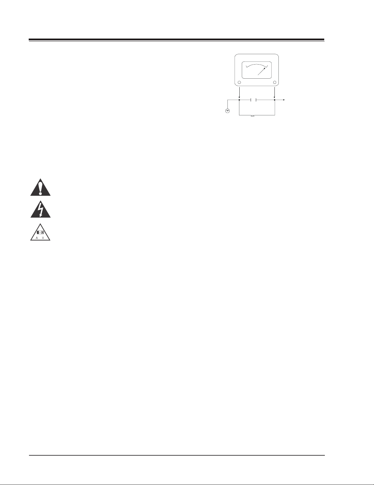
6. After reassembly of the set, always perform an AC leakage test on all exposed
metallic parts of the cabinet (the channel selector knobs, antenna terminals,
handle and screws) to be sure that set is safe to operate without danger of
electrical shock. DO NOT USE A LINE ISOLATION TRANSFORMER DURING THIS
TEST. Use an AC voltmeter having 5000 ohms per volt or more sensitivity in
the following manner: Connect a 1500 ohm, 10 watt resistor, paralleled by
a .15 mfd 150V AC type capacitor between a known good earth ground
water pipe, conduit, etc.) and the exposed metallic parts, one at a time.
Measure the AC voltage across the combination of 1500 ohm resistor and
.15 mfd capacitor. Reverse the AC plug by using a non-polarized adaptor
and repeat AC voltage measurements for each exposed metallic part. Voltage
measured must not exceed 0.75 volts RMS. This corresponds to 0.5 milliamp
AC. Any value exceeding this limit constitutes a potential shock hazard and
must be corrected immediately.
.C. Voltmeter
Good Earth Ground
such as the Water
Pipe, Conduit, etc.
0.15uF
1500 OHM
10 WATT
Place this probe
on each expose
metal part.
X-RADIATION
1. Be sure procedures and instructions to all service personnel cover the
subject of x-radiation. The only potential source of x-rays in current TV
receivers is the picture tube. However, this tube does not emit x-rays when
the HV is at the factory-specified level. The proper value is given in the
applicable schematic. Operation at higher voltages may cause a failure of
the picture tube or high-voltage supply and, under certain circumstances
may produce radiation in excess of desirable levels.
2. Only factory-specified CRT anode connectors must be used.
3. It is essential that the service personnel have available an accurate and
reliable high-voltage meter.
4. When the high-voltage circuitry is operating properly, there is no possibility
of an x-radiation problem. Every time a chassis is serviced, the brightness
should be run up and down while monitoring the high voltage with a
meter, to be certain that the high voltage does not exceed the specified
value and that it is regulating correctly.
5. When troubleshooting and making test measurements in a product with a
problem of excessively high voltage, avoid being unnecessarily close to
the picture tube and the high voltage power supply. Do not operate the
product longer than necessary to locate the cause of excessive voltage.
6. Refer to the CRT Anode High Voltage Measurement and Shutdown Adjustment
procedures described in the appropriate text (where used).
IMPLOSION
1. All direct view picture tubes are equipped with an integral implosion
protection system; take care to avoid damage during installation.
2. Use only the recommended factory replacement tubes.
TIPS ON PROPER INSTALLATION
1. Never install any receiver in a closed-in recess, cubbyhole, or closely
fitting shelf space over, or close to, a heat duct, or in the path of heated
air flow.
2. Avoid conditions of high humidity such as: outdoor patio installations
where dew is a factor, near steam radiators where steam leakage is a factor,
etc.
3. Avoid placement where draperies may obstruct venting. The customer
should also avoid the use of decorative scarves or other coverings that
might obstruct ventilation.
4. Wall- and shelf-mounted installations using a commercial mounting kit
must follow the factory-approved mounting instructions. A product mounted
to a shelf or platform must retain its original feet (or the equivalent
thickness in spacers) to provide adequate air flow across the bottom. Bolts
or screws used for fasteners must not touch any parts or wiring. Perform
leakage tests on customized installations.
5. Caution customers against mounting a product on a sloping shelf or in a
tilted position, unless the receiver is properly secured.
6. A product on a roll-about cart should be stable in its mounting to the cart.
Caution the customer on the hazards of trying to roll a cart with small
casters across thresholds or deep pile carpets.
7. Caution customers against using a cart or stand that has not been listed
by Underwriters Laboratories, Inc. for use with its specific model of
television receiver or generically approved for use with TVs of the same or
larger screen size.
8. Caution customers against using extension cords. Explain that a forest of
extensions, sprouting from a single outlet, can lead to disastrous
consequences to home and family.
VR168 - 923-03485 D35E COMBO - SAFETY
i
Page 3

TABLE OF CONTENTS
SECTION 1 SUMMARY 1-1
SPECIFICATIONS ..........................................1-1
KEY TO ABBREVIATIONS ................................1-2
SERVICING PRECAUTIONS ..............................1-3
PACKAGE CONTENTS .....................................1-4
SECTION 2 CHASSIS 2-1
CABINET .................................................... 2-1
EXPLODED DIAGRAM .....................................2-1
SELF DIAGNOSTICS .......................................2-2
CABINET DISASSEMBLY ................................. 2-3
CIRCUIT BOARD DISASSEMBLY........................2-4
SECTION 3 ELECTRICAL 3-1
DVD TROUBLESHOOTING ................................ 3-1
VCR TROUBLESHOOTING .............................. 3-17
SECTION 4 MECHANICAL 4-1
VCR DECK MECHANISM .................................. 4-1
VCR ALIGNMENT ........................................ 4-13
MAINTENANCE/INSPECTION PROCEDURE ......... 4-19
VCR MECHANISM TROUBLESHOOTING ............. 4-23
DVD DECK MECHANISM ............................... 4-29
MECHANISM DISASSEMBLY........................... 4-30
DECK MECHANISM ADJUSTMENT ................... 4-32
SECTION 5 PARTS 5-1
COMPONENT PARTS .......................................... 5-2
SECTION 6 DIAGRAMS 6-1
EXPLODED VIEW ........................................... 6-1
VCR EXPLODED VIEW .....................................6-2
DVD EXPLODED VIEW ..................................... 6-3
MAIN BLOCK DIAGRAM ..................................6-4
POWER BLOCK DIAGRAM ................................ 6-5
TUNER-IF BLOCK DIAGRAM.............................6-6
Y/C BLOCK DIAGRAM ..................................... 6-7
AUDIO BLOCK DIAGRAM ................................. 6-8
HIFI BLOCK DIAGRAM ................................... 6-9
SYSTEM BLOCK DIAGRAM ............................. 6-10
SECTION 7 SCHEMATICS 7-1
POWER SUPPLY CIRCUIT ................................7-1
TUNER/IF CIRCUIT ....................................... 7-2
AV CIRCUIT ................................................. 7-3
HIFI CIRCUIT ..............................................7-4
SYSTEM CIRCUIT .......................................... 7-5
DVD CIRCUIT ...............................................7-6
DRIVE RF CIRCUIT ........................................ 7-7
MPEG CIRCUIT .............................................7-8
AUDIO CIRCUIT............................................7-9
MICRO CIRCUIT.......................................... 7-10
JACKPACK CIRCUIT ..................................... 7-11
VCR PCB LAYOUT ........................................ 7-12
DVD PCB LAYOUT TOP.................................. 7-13
DVD PCB LAYOUT BOTTOM ............................ 7-14
OTHER PCB LAYOUTS ................................... 7-15
WAVEFORMS .............................................. 7-16
VR168 - 923-03485 D35E COMBO - TOC
TOC-1
Page 4

- TOC-2 -
Page 5

section 1 SUMMARY
SUMMARY
SPECIFICATIONS
DVD PART
Power supply ........................................ AC 120 V, 60 Hz
Power .................................................. 23 W
Mass .................................................... 3.0kg(6.6lbs)
External dimensions .............................. 430 x 88 x 247 (W x H x D)
Signal system ....................................... PAL 625/50, NTSC 525/60
Laser ................................................... Semiconductor laser, wavelength 650nm
Frequency range ................................... (digital audio) 4 Hz to 20 kHz
Signal-to-noise ratio ............................. (digital audio) More than 100 dB (EIAJ)
Audio dynamic range ............................. (digital audio) More than 95 dB (EIAJ)
Harmonic distortion .............................. (digital audio) 0.008%
Wow and flutter ....................................Below measurable level (less than +0.001% (W.PEAK) (EIAJ)
Operating Temperature ........................... 5°C (41°F) to 35°C (95°F)
OUTPUTS
Video outputs ...................................... 1.0V (p-p), 75., negative sync., RCA jack x 1
S video outputs .................................... (Y) 1.0V (p-p), 75., negative sync.,Mini DIN 4-pin x 1
(C)0.3V(p-p), 75.
Component video .................................. output (Y) 1.0 V (p-p), 75 ., negative sync., RCA jack x 1
(Pb)/(Pr) 0.7 V (p-p), 75 .
Audio output ....................................... (digital audio) 0.5V (p-p), 75., RCA jack X 1
Audio output ....................................... (optical audio) Optical connector x 1
Audio output ....................................... (analog audio) 2.0Vrms (1kHz,0dB), RCA jack (L,R) x 1
VHS PART
Video Head System ................................ Double azimuth 4 heads, helical scanning
RF Modulator........................................ UHF 28-68 (Adjustable)
Tape format .......................................... Tape width 12.7 mm (0.5 inch)
Timer ................................................... 24 hours display type
*Designs and specifications are subject to change without notice.
*Weight and dimensions shown are approximate.
VR168 - 923-03485 1-1 D35E COMBO - SUMMARY
Page 6

KEY TO ABBREVIATIONS
A
AC
ACC
ADJ
A/E
AFC
AFT
AGC Automatic Gain Control
ALC
AM
AMP
ANT
APC
ASS’Y
AUD
AUTO
AUX
B
B
C
BPF
BW or B/W
C
CAN
CAP
CATV
CBA
CCD
CFG
CH
CHROMA
CLK
CNR
COMB
COMP
CONV
CS
CST
CTL
CUR
CYL
D
dB
DC
DEMOD
DET
DEV
DHP
DIGITRON
DL
DOC
D/V
E
EE
EMP
EP
EQ
ES
F
FB
FBC
FE
FF
FG
FL
FM
F/R
FS
FSC
F/V
FWD
GEN
GND
H
Hz
IC
IF
INS
I/O
L
LD
LECHA
LP
LPF
D
E
F
G
H
I
L
Alternating Current
Automatic Color Control
Adjust
Audio Erase
Automatic Frequency Control
Automatic Fine Tuning
Automatic Level Control
Amplitude Modulation
Amplifier
Antenna
Automatic Phase Control
Assembly
Audio
Automatic
Auxiliary
Base
Bandpass Filter
Black and White
Capacitor, Chroma, Collector
Cancel
Capstan
Cable Television
Circuit Board Assembly
Charge Coupled Device
Capstan Frequency Generator
Channel
Chrominance
Clock
Chroma Noise Redution
Combination
Comb Filter
Comparator
Composite
Compensation
Converter
Chip Select
Cassette
Control
Current
Cylinder
Drum, Digital, Diode, Drain
Decibel
Direct Current
Demodulator
Detector
Deviation
Double High Pass
Digital Display Tube
Delay line
Drop Out Compensator
Dummy Vertical
Emitter
Electric to Electric
Emphasis
Extended Play
Equalizer
Electrostatically Sensitive
Fuse
Feed Back
Feed Back Clamp
Full Erase
Fast Forward
Frequency Generator
Filter
Frequency Modulation
Front/Rear
Frequency Synthesizer
Subcarrier Frequency
Frequency Voltage
Forward
Generator
Ground
High, Horizontal
Hertz
Integrated Circuit
Intermediate Frequency
Insert
Input/Output
Low, Left, Coil
LED
Letter Character
Long Play
Low Pass Filter
SUMMARY
M
MAX
MD
MIC
MIN
MIX
MM
MMV
MOD
MODEM
NR
OSC
OSD
PB
PCB
PG
PLL
P. P
PRE-AMP
PS
PWM
Q
QH
QSR
QTR
QV
R
RE(or RC)
REC
REF
REG
REMOCON
REV
REW
RF
R/P
RTC
S
SH
SHARP
SIF
SLD
S/N
SP
SUB
SW or S/W
SYNC
SYSCON
T
TP
TR
TRK
TRANS
TU
UHF
UNREG
V
VA
VCO
VGC
VHF
VISS
VR
V-SYNC
VTG
VV
VXO
W
WHT
W.O
X-TAL
Y/C
YNR
ZD
N
O
P
Q
R
S
T
U
V
W
X
Y
Z
Maximum
Modulator
Microphone
Minimum
Mixer, Mixing
Monostable, Multivibrator
Mono Multi Vibrator
Modulation, Modulator
Modulator-Demodulator
Noise Reduction
Oscillator
On Screen Display
Playback
Printed Circuit Board
Pulse Generator
Phase Locked Loop
Peak-to-Peak
Preamplifier
Phase Shift
Pulse Width Modulation
Transistor
Quasi Horizontal
Quick Setting Record
Quick Timer Record
Quasi Vertical
Resistor, Right
Remocon, Receiver
Recording
Reference
Regulated, Regulator
Remote Control(unit)
Reverse
Rewind
Radio Frequency
Record/Playback
Reel Time Counter
Serial
Shift
Sharpness
Sound Intermediate Frequency
Side Locking
Signal to Noise Ratio
Standard Play
Subtract, Subcarrier
Switch
Synchronization
System Control
Coil
Test Point
Transistor
Tracking
Transformer
Tuner,Take-up
Ultra High Frequency
Unregulated
Volt, Vertical
Always Voltage
Voltage Controlled Oscillator
Voltage Gain Control
Very High Frequency
VHS Index Search
Variable Resistor or Volume
Vertical Synchronization
Voltage
Voltage to Voltage
Voltage X-tal Oscillator
Watt
White
With out
Crystal
Luminance/Chrominance
Luminance Noise Reduction
Zener Diode
VR168 - 923-03485 1-2 D35E COMBO - SUMMARY
Page 7

SUMMARY
SERVICING PRECAUTIONS
CAUTION: Before servicing the product covered by this
service data and its supplements and addends, read and
follow the SAFETY PRECAUTIONS.
NOTE: if unforeseen circumstances create conflict between
the following servicing precautions and any of the
safety precautions in this publication, always follow
the safety precautions.
GENERAL SERVICING PRECAUTIONS
1. Always unplug the product AC power cord from the
AC power source before:
(1) Removing or reinstalling any component, circuit
board, module, or any other assembly.
(2) Disconnecting or reconnecting any internal elec-
trical plug or other electrical connection.
(3) Connecting a test substitute in parallel with an
electrolytic capacitor.
CAUTION: A wrong part substitution or incorrect polarity
installation of electrolytic capacitors may result in
an explosion hazard.
2. Do not spray chemicals on or near this product or
any of its assemblies.
3. Unless specified otherwise in this service data, clean
electrical contacts by applying an appropriate contact cleaning solution to the contacts with a pipe
cleaner, cotton-tipped swab, or comparable soft applicator. Unless specified otherwise in this service
data, lubrication of contacts is not required.
4. Do not defeat any plug/socket B+ voltage interlocks
with which instruments covered by this service
manual might be equipped.
5. Do not apply AC power to this product and/or any of
its electrical assemblies unless all solid-state device
heat sinks are correctly installed.
6. Always connect the test instrument ground lead to
the appropriate ground before connecting the test
instrument positive lead. Always remove the test instrument ground lead last.
INSULATION CHECKING PROCEDURE
Disconnect the attachment plug from the AC outlet and
turn the power on. Connect an insulation resistance meter
(500V) to the blades of the attachment plug. The
insulation resistance between each blade of the
attachment plug and accessible conductive parts should
be more than 1Mohm. Accessible conductive parts
include metal panels, input terminals, earphone jacks,
etc.
ELECTROSTATICALLY SENSITIVE (ES) DEVICES
Some semiconductor (solid state) devices can be
damaged easily by static electricity. Such components
commonly are called Electrostatically Sensitive (ES)
Devices. Examples of typical ES devices are integrated
circuits and some field effect transistors and
semiconductor chip components. The following
techniques should be used to help reduce the incidence
of component damage caused by static electricity.
1. Immediately before handling any semiconductor component or semiconductor-equipped assembly, drain
off any electrostatic charge on your body by touching a known earth ground. Alternatively, obtain and
wear a commercially available discharging wrist strap
device, which should be removed for potential shock
reasons prior to applying power to the unit under
test.
2. After removing an electrical assembly equipped with
ES devices, place the assembly on a conductive surface such as aluminum foil, to prevent electrostatic
charge buildup or exposure of the assembly.
3. Use only a grounded-tip soldering iron to solder or
unsolder ES devices.
4. Use only an anti-static solder removal device. Some
solder removal devices not classified as “anti-static”
can generate electrical charges sufficient to damage
ES devices.
5. Do not use freon-propelled chemicals. These can generate an electrical charge sufficient to damage ES
devices.
6. Do not remove a replacement ES device from its protective package until immediately before you are
ready to install it. (Most replacement ES devices are
packaged with leads electrically shorted together by
conductive foam, aluminum foil, or comparable conductive material).
7. Immediately before removing the protective material from the leads of a replacement ES device, touch
the protective material to the chassis or circuit assembly into which the device will be installed.
Caution: Be sure no power is applied to the chassis or circuit,
and observe all other safety precautions.
8. Minimize bodily motions when handling unpackaged
replacement ES devices. (Normal harmless motion such
as the brushing together of your clothes fabric or
the lifting of your foot from a carpeted floor can
generate static electricity sufficient to damage an
ES device.)
VR168 - 923-03485 1-3 D35E COMBO - SUMMARY
Page 8

PACKAGE CONTENTS
SUMMARY
BATTERY
REMOCON
PACKING
CABLE SET ASS'Y
RF CABLE
PHONO CORD 1WAY
PHONO CORD 2WAY
OWNER'S MANUAL
PAC KIN G S HE ET
PAC KI NG
BOX CARTON
OPTIONAL PARTS
VR168 - 923-03485 1-4 D35E COMBO - SUMMARY
Page 9
section 2 CHASSIS
Angle icon indi
s
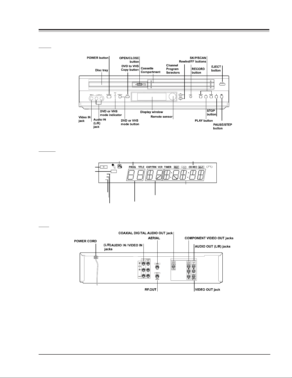
CABINET
FRONT
DISPLAY
CHASSIS
BACK
Repeat playback
mode indicators
Stereo indicator
DVD indicator
Video CD indicator
AB
VCD
DVD
ST
ALL MP3
-R W
BIL PR
SAP CH
cator
PROGRAM indicator
Title number indicator
CD REC indicator
AM
SP
LP
EP
Total playing time/elapsed time indicator
Chapter/Track number indicator
EXPLODED DIAGRAM
See page 6-1 for a detailed exploded view.
VR168 - 923-03485 2-1 D35E COMBO - CHASSIS
Page 10

CHASSIS
SELF DIAGNOSTICS
SELF DIAGNOSTIC OVERVIEW
Provides service personnel a convenient service aid by a
visual display of error codes generated by the
microcomputer and displayed on the digitron.
OPERATIONAL PROCEDURE
With the remote control, press and hold the “MENU” key
until the word MENU appears in the display. Then press
4, 3, 2, 1 and then “ENTER”. The self diagnostic procedure
will sequence through the 8 step procedure. If an error
is detected, a code number will flash approximately 5
times and then return to its initial mode of operation.
DISPLAY
“D1”
“D2”
DESCRIPTION INPUT SIGNAL CIRCUIT STATUS SERVICE POINTS
•Tape Loading
Error
•Tape Loading
Error
•Mode SW
Pos. S1, S2, S3, S4
Pins: 25, 24, 23, 22
•Load Motor
Pins: 60 (+)
Pins: 59 (-)
•Mode SW
Pos. S1, S2, S3, S4
Pins: 25, 24, 23, 22
•Load Motor
Pins: 60
NOTES
1. Error codes will not be stored. The program must be
re-initialized as described in the preceding step.
2. Pin numbers refer to IC501 microcomputer, unless
otherwise stated.
•Mode SW Position not
changed within 6 seconds
after cassette loading
attempt.
•Mode SW Position not
changed within 6 seconds
after cassette loading
attempt.
•Loading motor,
mech problems,
gears, timing
•Mode SW Position
•Mode SW Contacts
“D3”
“D4”
“D5”
“D6”
“D7”
“F1”
•CST Loading
Error
•CST Loading
Error
•DRUM Motor
Error
•Reel Rotational
Error
•Capstan Motor
Error
•Tuner Signal
Input
•Mode SW
Pos. S1, S2, S3, S4
Pins: 25, 24, 23, 22
•Load Motor
Pins: 60
•Mode SW
Pos. S1, S2, S3, S4
Pins: 25, 24, 23, 22
•Load Motor
Pins: 60
•Head SW(30Hz)
Pulses Pin18
•Supply Take-up Reel
Pulses, Pins 79, 80
•Capstan FG Pulses
•CVin Pin 56
•Mode SW Position not
changed within 6 seconds after cassette
loading attempt.
•CST SW must be activated within 3 seconds, otherwise unit shut down will
occur.
•Drum Motor (Slow Start)
•Motor must be up to
speed within 3 seconds
of operation
•CFG Signal present, but
take-up pulses are missing.
(Capstan motor running)
•No CFG Signal
•Composite Sync not
detected, RF or Video
Signal loss.
•Mode SW Contacts
•CST SW or
Connector Contacts
•Drum Motor and
Control Circuits
•Capstan belt
•Idler and reel gears
damaged
•ST/U Sensors
•Capstan control ckt.
•Motor assy.
•IC501 Ckt.
•Loss of C-sync
Tuner Line
Video Path
VCR should be in PB mode for D5, D6 and D7. Stop mode for F1, cassette loading D3, D4 and tape loading D1 and D2.
VR168 - 923-03485 2-2 D35E COMBO - CHASSIS
Page 11
CHASSIS
CABINET DISASSEMBLY
CAUTION BEFORE SERVICING
Electronic parts are susceptible to static electricity and
may easily be damaged. Follow proper grounding
procedures.
Many screws are used inside the unit. To prevent missing,
dropping, etc. of the screws, always use a magnetized
screw driver in servicing. Several kinds of screws are used
and some of them need special cautions. That is, take
care of the tapping screws securing molded parts and
fine pitch screws used to secure metal parts. If they are
used improperly, the screw holes will be easily damaged
and the parts can not be fixed.
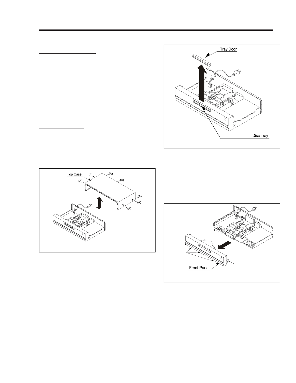
CABINET DISASSEMBLY
TOP CASE
1. Remove 7 screws (A). (See Fig. 2-1)
2. Pull the top case back and up, in the direction of
the arrow, to disengage it from the front panel.
Fig. 2-2
FRONT PANEL
1. Eject the disc tray. (See Fig. 2-2)
2. Remove the tray door. (See Fig. 2-2)
3. Depress the 7 embossed tabs (see fig. 2-3) and
remove the Front panel.
Tabs
Fig. 2-1
Tabs
TRAY DOOR
1. Eject the disc tray.
2. Lift up the tray door in the direction of the arrow.
VR168 - 923-03485 2-3 D35E COMBO - CHASSIS
Fig. 2-3
Tab
Page 12
CHASSIS
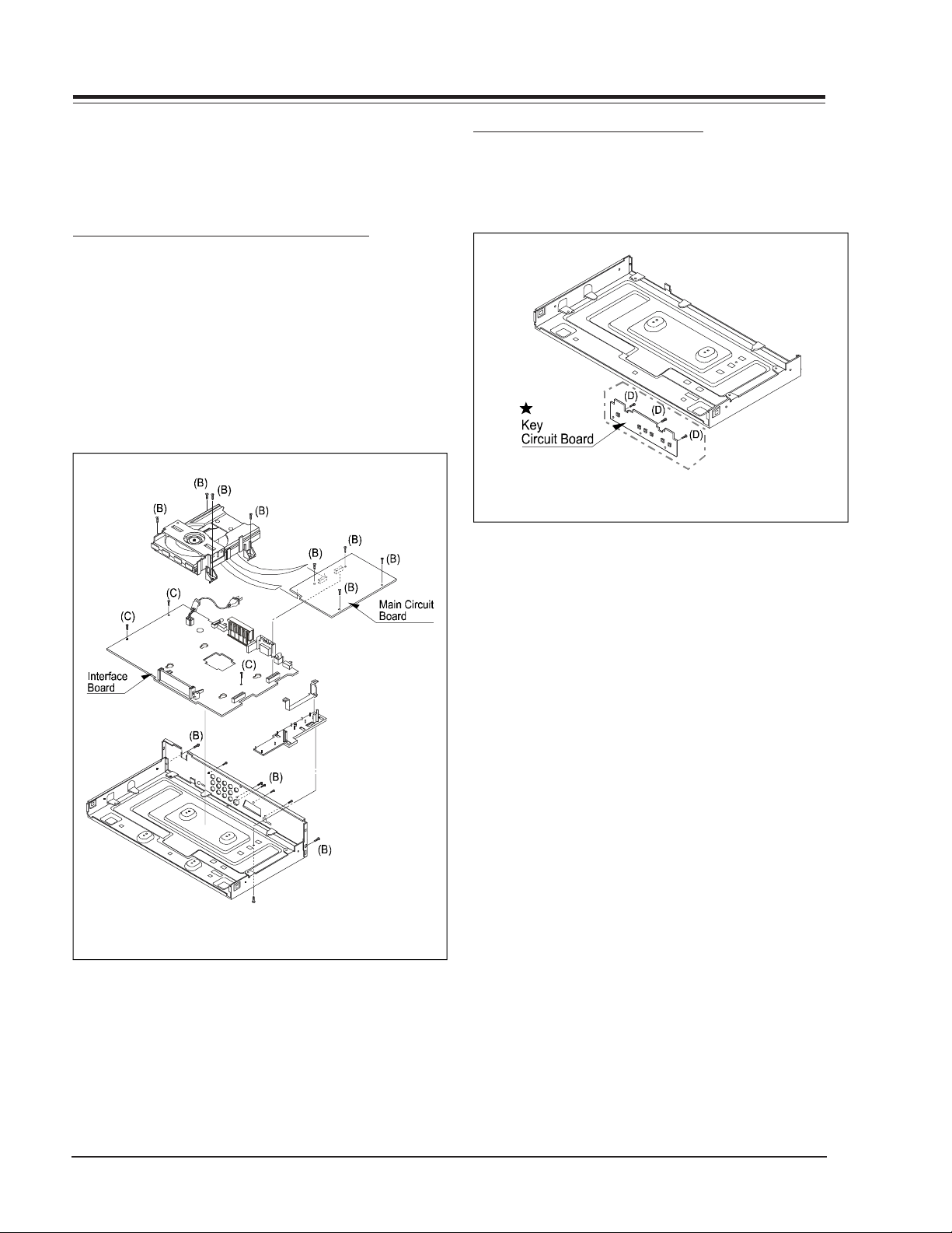
CIRCUIT BOARD DISASSEMBLY
Note: Before removing the main circuit board, be sure
to short circuit the laser diode output land. After
replacing the main circuit board, open the land after
inserting the flexible connector.
MAIN CIRCUIT BOARD AND INTERFACE BOARD
1. Remove the top case. (See Fig. 2-1)
2. Remove 14 screws (B).
3. Remove the Deck from the Main Circuit Board.
4. Remove the Main Circuit Board from the Interface
Board.
5. Remove 2 screws (C).
6. Remove the Interface Board from the chassis.
DIGITRON AND KEY CIRCUIT BOARD
1. Remove the front panel. (See Fig. 2-3)
2. Release 3 screws (D), and remove the digitron circuit board.
Fig. 2-5
Fig. 2-4
VR168 - 923-03485 2-4 D35E COMBO - CHASSIS
Page 13
SECTION 3 Electrical
T
TROUBLESHOOTING
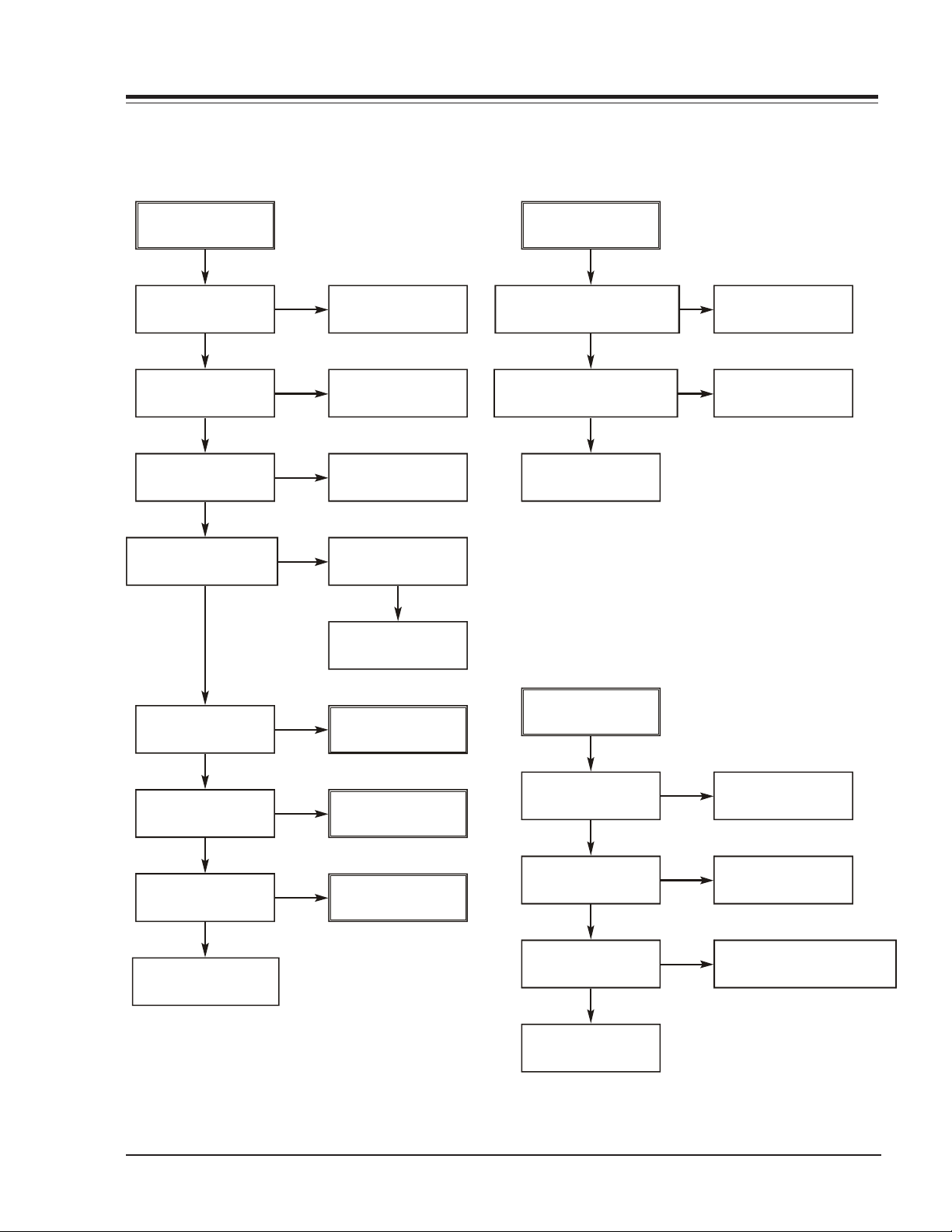
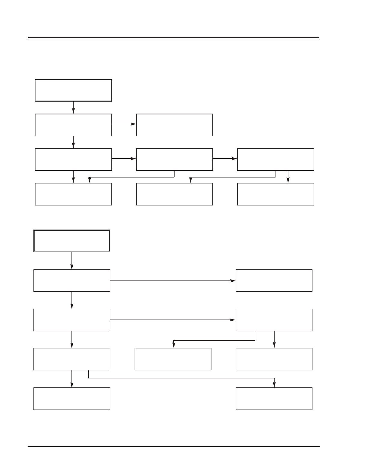
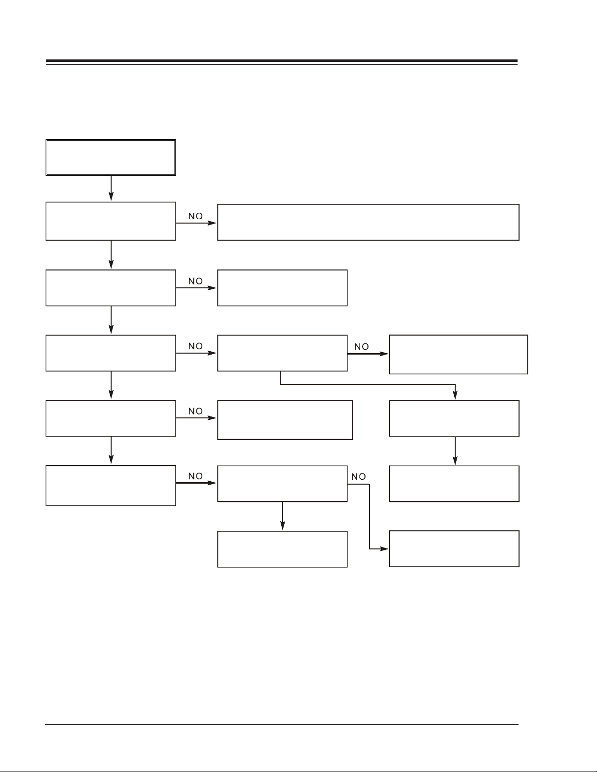
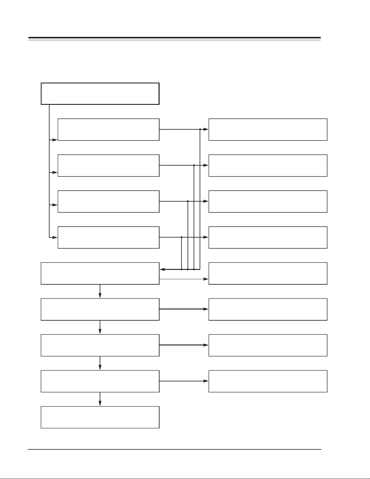
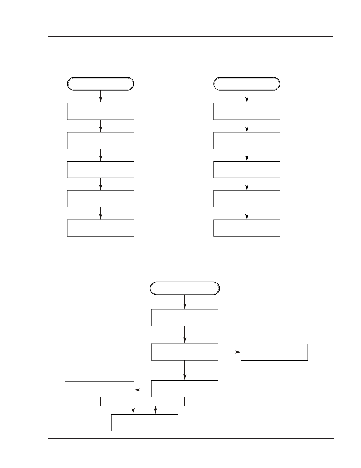
1. Power(SMPS) CIRCUI
ELECTRICAL
(1) No 5.3VA (SYS/Hi-Fi/TUNER)
NO 5.3VA.
YES
Is F101 normal?
YES
Is R101
normal?
YES
Is Bd101
normal?
YES
Is Vcc (8.5~21V)
supplied to IC101 Pin7?
YES
NO
NO
NO
NO
Replace F101.
Replace
BD101.
Replace R101.
Is D102
normal?
N O
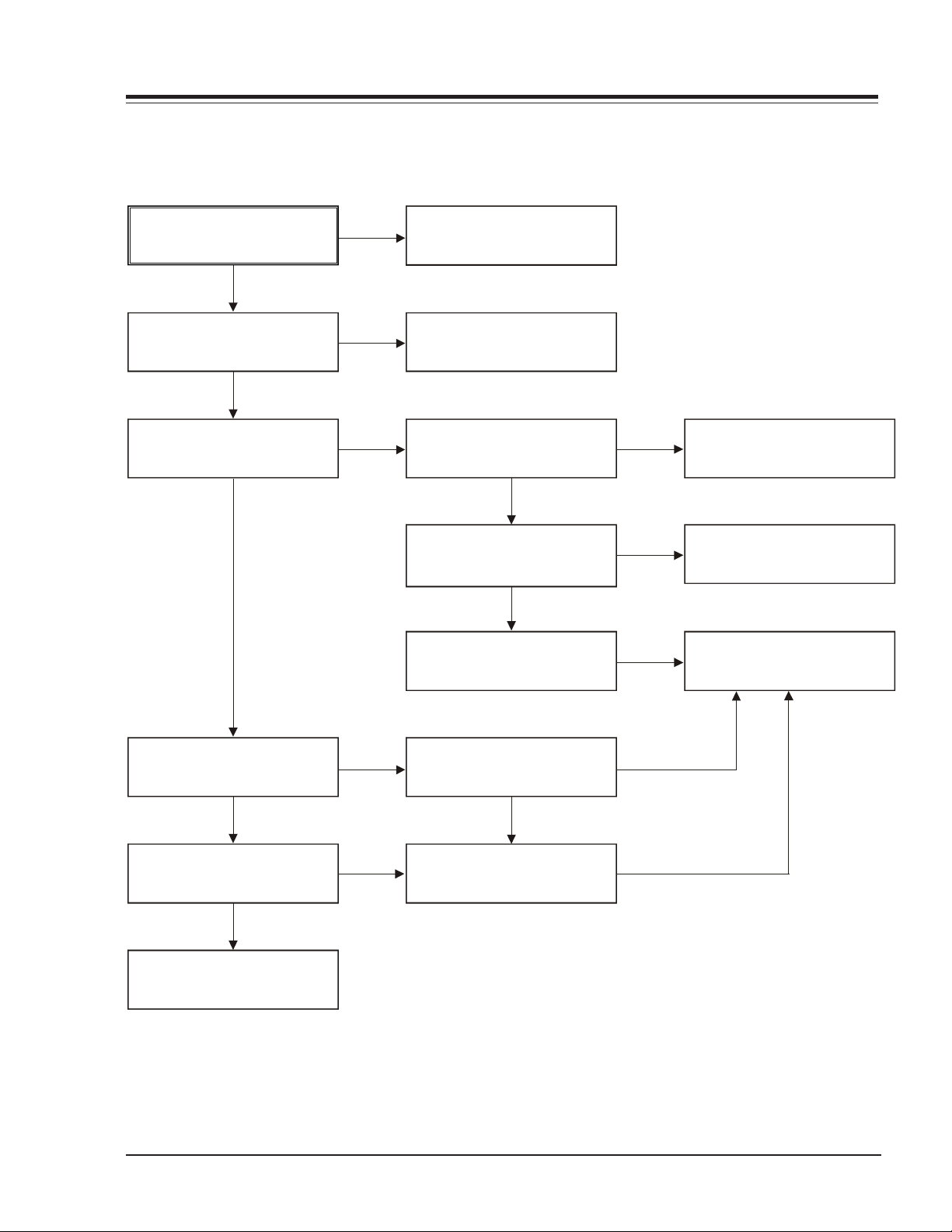
(2) No 12VA (TO CAP, DRUM MOTOR)
NO 12VA.
YES
Is the Vcc (13V) supplied to (+)
terminal in D115 and D117?
YES
Is the Vcc (12V) supplied to (-)
terminal in D115 and D117?
YES
Check or Replace
the Motor Vcc.
NO
NO
Check or Replace
D110.
Replace D115,
Is the D112 normal?
YES
Is there about 2.5V
at the IC102 Vref?
YES
Is D110 normal?
YES
Check the Main PCB
5.3VA/5.0V Line short?
Check or Replace
D102.
(3) No 5.2V (SYS/Hi-Fi/TUNER)
N O
N O
N O
Replace D112.
Replace IC102.
Replace the D110.
NO 5.2VA.
YES
Is 5.3VA put into
Q116 Emitter?
YES
Is Q115 Base
“H”?
YES
Is about 5V put into
Q116 Base?
YES
Check or Replace
Q115/Q116
NO
NO
NO
5.3VA Line Check.
Check the Power
Control.
Check or Replace Q115,
R160, R161, R162, D122.
VR168 - 923-03485 3-1 D35E COMBO - ELECTRICAL
Page 14
TROUBLESHOOTING (CONTINUED)
ELECTRICAL
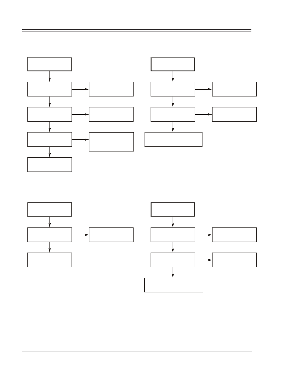
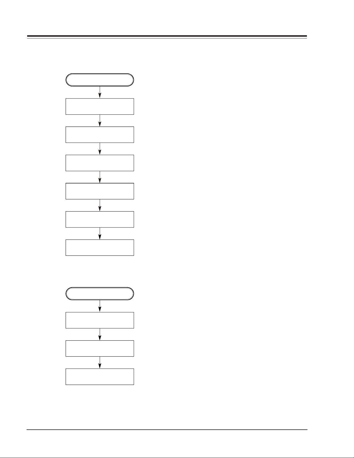
(4) No 5V (TO DVD)
NO 5V.
YES
Is 5.3VA present on
Q113 Emitter?
YES
Is the Q115 Base
“H”?
YES
Is about 5V present on
Q113 Base?
YES
Check or Replace
Q113/Q115
NO
NO
NO
5.3VA Line Check.
Check the Power
Control.
Check or Replace
Q115, R157, R158,
R159, D121.
(5) No REG 5V (AVCP)
No REG 5V.
YES
Is 5.3VA present on
Q117 Collector?
YES
Is 33V present on
Q117 Base?
YES
Check or Replace Q117,
R167, ZD105, C162.
NO
NO
5.3VA Line Check.
Check 33V Line.
(6) No 33V (TUNER)
No 33V.
YES
Is Q115 Base “H”?
YES
Check or Replace
Q114, R154, R155.
(7) No REG 12V
No REG 12V.
YES
N O
Check the Power
Control.
Is 13V present on
Q112 Collector?
YES
Is 33V present on
Q112 Base?
YES
Check or Replace Q112,
ZD103, R153, C151.
NO
NO
Check or Replace
D110.
Check 33V Line.
VR168 - 923-03485 3-2 D35E COMBO - ELECTRICAL
Page 15
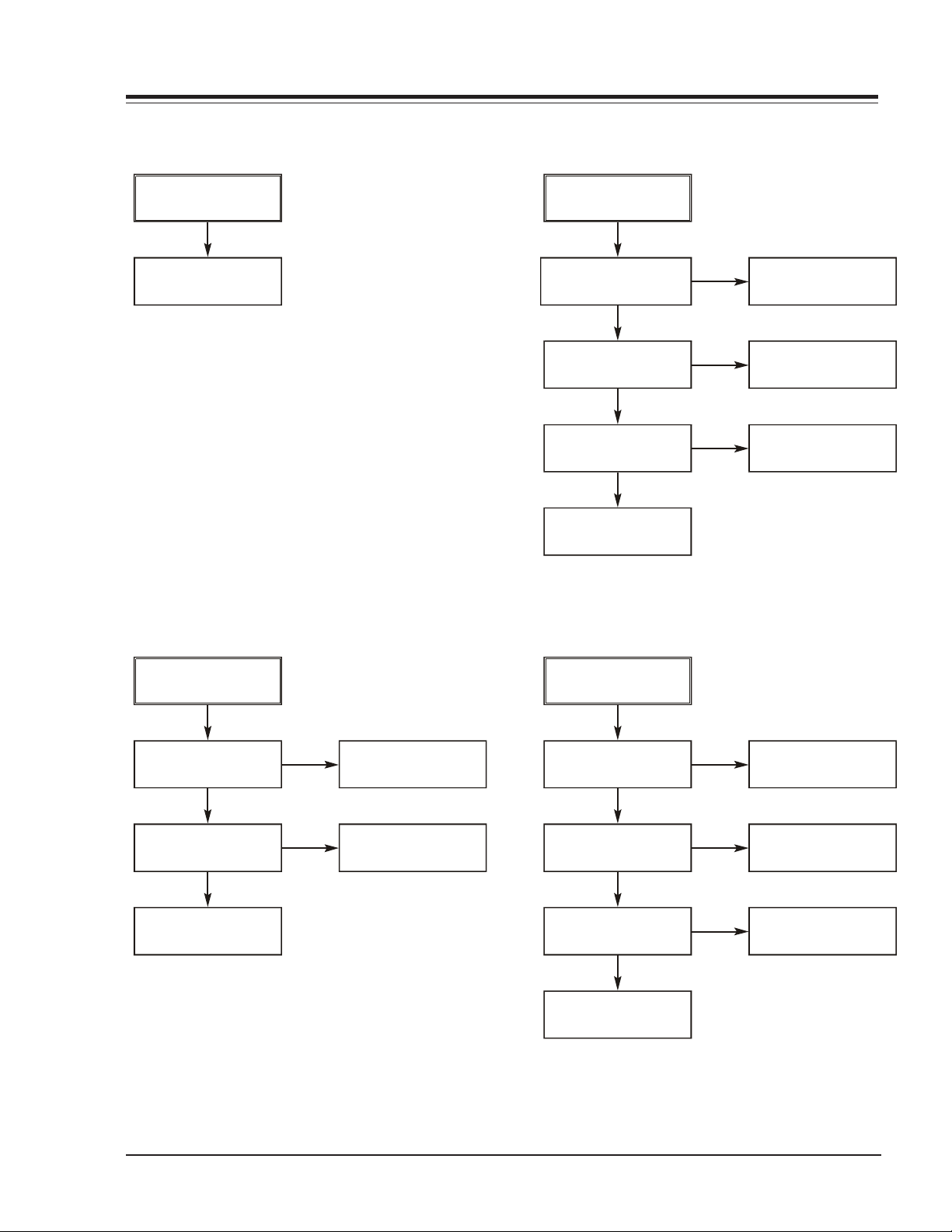
(8)
TROUBLESHOOTING (CONTINUED)
No -29VA.
ELECTRICAL
(9) No 8VA
No -29VA.
YES
Check or Replace
D108.
(10) No 3.3VA
NO 8VA.
YES
Is Vcc (13V) supplied to
(+) terminal in D114?
YES
Is Vcc (12V) supplied
to IC106 Pin1?
YES
Is Q115 Base
“H”?
YES
Check or Replace
IC106, R170, C154.
(11) No 2.5V
NO
NO
NO
Check or Replace
D110.
Check or Replace
D114.
Check the Power
Control.
No 3.3V
YES
Is Vcc (4V) supplied
to IC103 Pin1?
YES
Is the Q115 Base
“H”?
YES
Check or Replace
IC103, R156, C153.
NO 2.5VA.
YES
N O
N O
Check or Replace
D111.
Check the Power
Control.
Is Vcc (4V) supplied
to IC104 Pin1?
YES
Is the Q115 Base
“H”?
YES
Is Vcc (3.3V) supplied
to IC104 Pin2?
YES
Check or Replace
D119, C159.
NO
NO
NO
Check or Replace
D111.
Check the Power
Control.
Check or Replace
Ic104.
VR168 - 923-03485 3-3 D35E COMBO - ELECTRICAL
Page 16
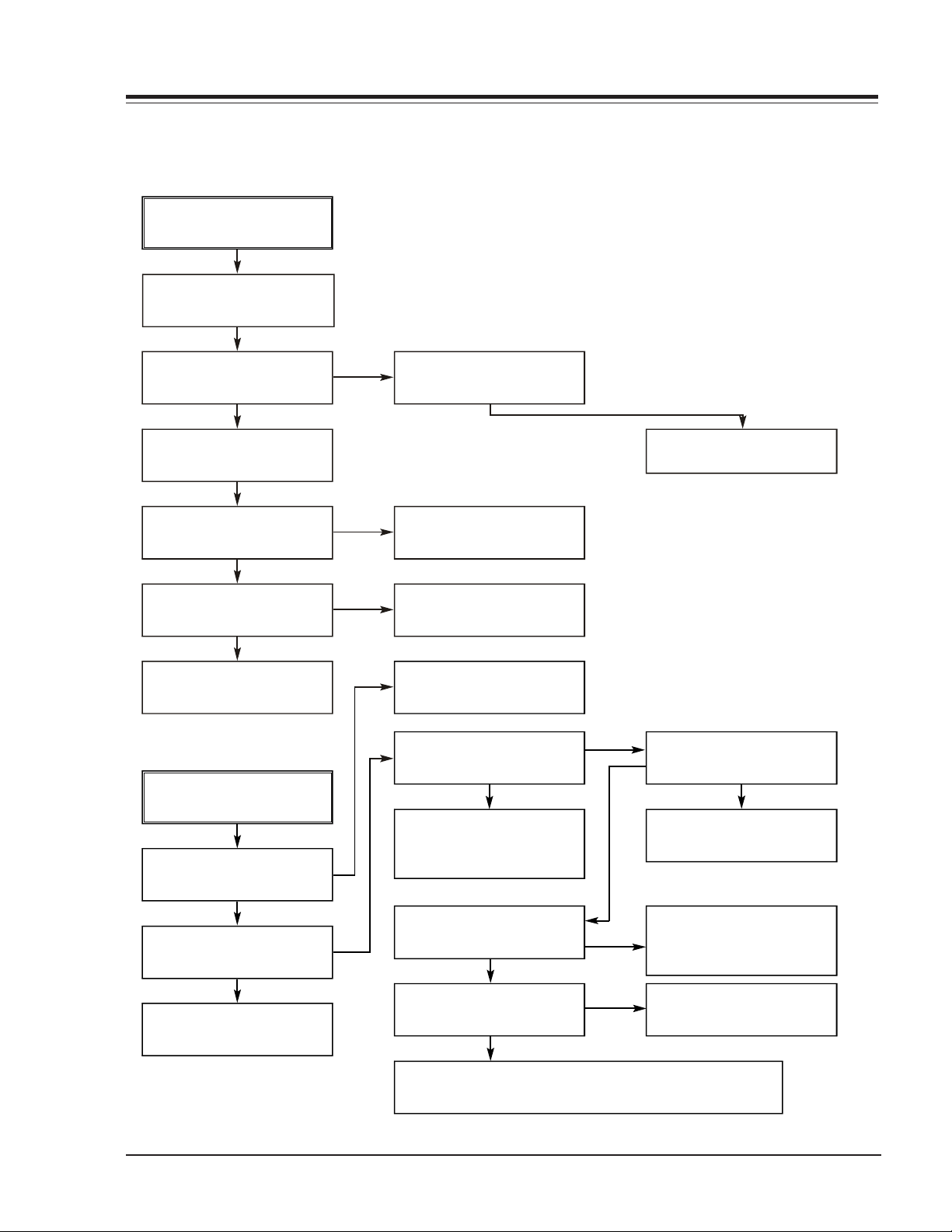
TROUBLESHOOTING (CONTINUED)
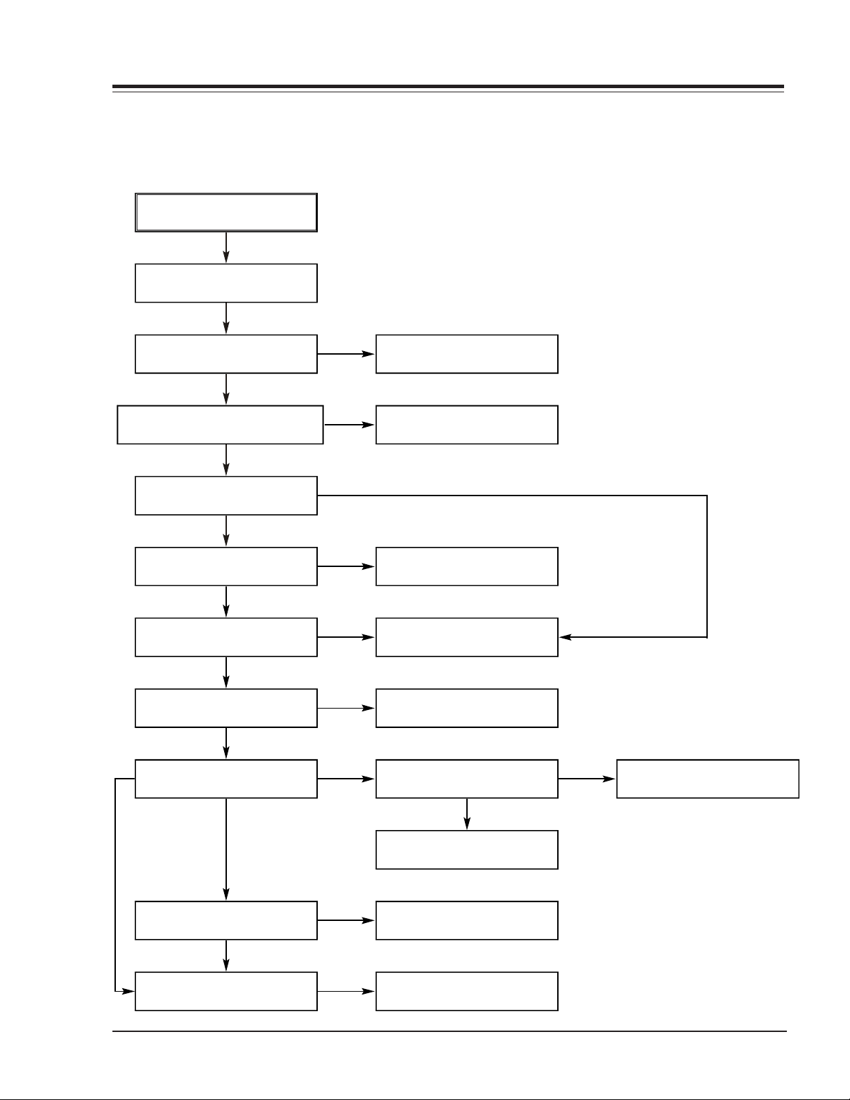
2. SYSTEM/KEY CIRCUIT
(1) AUTO STOP
Auto Stop
YES
ELECTRICAL
Does the SW30 waveform
appear at IC501
Pin24?
YES
Do the T-UP Reel Pulses
appear at IC501 Pin4?
YES
Replace Ic501.
(2) The unstable loading of a Cassette tape
The unstable loading of a
Cassette tape
YES
Is 12V applied to
PMC01 Pin8?
YES
NO
NO NO
O
N
Check the Drum Motor
signal.
Do T/UP Reel Pulses
appear at Q514
Base terminal ?
YES YES
Replace the T/UP Reel
Sensor (RS501).
12 Volt Trouble Shooting”.
Does 5.2V appear at
RS501?
NO
Check the Q116 Power
Circuit.
Refer to “SMPS DRUM
Does the “H” signal appear
at Ic501 Pin57 during
inserting the CST ?
YES
Does the “L” signal appear
at Ic501 Pin19 during
inserting the CST?
YES
Check the Deck
Mechanism.
Caution: Auto stop can occur because Grease or Oil is dried up
VR168 - 923-03485 3-4 D35E COMBO - ELECTRICAL
O
NO
N
Check the CST SW and
the peripheral circuitry.
Is 5.3V applied to
R544 ?
YES
Refer to SMPS 5.3VA
troubleshooting.
Check IC501
Pins74, 75, 76, 77.
NO
Page 17
TROUBLESHOOTING (CONTINUED)
3. SERVO CIRCUIT
(1) Unstable Video in PB MODE
Unstable Video in
PB Mode.
YES
Does the Noise level of the
screen change periodically?
YES
ELECTRICAL
Do the CTL pulses appear
at IC501 Pin37?
Does the CFG waveform
appear at IC501
On tracking do the CTL
pulses move?
Does the Video Envelope
waveform appear at
IC501 Pin12?
Replace 501.IC
(2) When the Drum Motor
doesn’t run.(2)
When the Drum Motor
Does 12V appear at
PMC01 Pin8?
Does 2.8V appear at
PMC01 Pin12?
Check the connector
(PMC01) and the Drum
Motor Ass’y.
YES
Pin40?
YES
YES
YES
doesn’t run,
YES
YES
NO
NO
NO
O
O
Is the adjustment height of
the CTL Head accurate?
Replace 501.IC
Refer to “When the Y signal
doesn’t appear on the
screen in PB Mode”.
Refer to “(2)
No 12VA of Power section”
Do the Drum PWM Pulses
appear at 501
Are the foil patterns and
the Components between
IC501 Pin26 and PMC01
Pin12 short?
Do the DFG Pulses appear
at the IC501 Pin38?
N
Do the Drum PWM Pulses
appear at 501
N
IC
Pin26?
YES
YES
IC
Pin26?
YES
NO
NO
NO
NO
Readjust the height of the
CTL Head
Do the DFG Pulses appear
at PMC01 Pin11?
YES
NO
Replace the Cap M.
Aren’t the foil patterns and
the Components between
IC501 Pin 38 and PMC01
Pin11 short?
Replace 501.IC
Are the connecting patterns and the Components
between IC501 Pin26 and PMC01 Pin11 short?
VR168 - 923-03485 3-5 D35E COMBO - ELECTRICAL
Page 18
TROUBLESHOOTING (CONTINUED)
(3) When the Capstan Motor doesn’t run
When the Capstan Motor doesn’t run,
ELECTRICAL
Does 12VA appear at PMC01?
YES
Does 2.8V appear at PMC01?
YES
Check PMC01 and the Capstan
Motor Ass’y.
Are the foil patterns and Components
between IC501 Pin25 and PMC01
Pin9 short?
Does the CFG signal come into
IC501 Pin40?
NO
NO
YES
YES
Refer to “SMPS (CAPSTAN/12Volt)
Trouble Shooting”.
Does the PWM signal appear at
IC501 Pin25?
NO
Does the CFG signal appear at
PMC01 Pin1?
NO
Check the Capstan Motor Ass’y.
N O
YES
Does the Capstan PWM signal appear at
IC501 Pin25?
N O
YES
Are the foil patterns and Components
between IC501 Pin 25 and PMC01
Pin9 short?
VR168 - 923-03485 3-6 D35E COMBO - ELECTRICAL
Are the foil patterns and component
between IC501 Pin40 and PMC01
Pin1 short?
Replace IC501.
Page 19
TROUBLESHOOTING (CONTINUED)
KEY doesn't work.
(3)
KEY doesn’t work.
ELECTRICAL
Is 5V applied to
IC501 Pin 15?
YES
Does LED or FLD change
when a function button is
pressed?
4. OSD CIRCUIT
1) No OSD display.
No OSD display.
Is 5.3V applied to
IC501 Pin 42?
YES
Does oscillation occur at
IC501 Pins 52, 53?
YES
Does oscillation occur at
IC501 Pins 50, 51?
YES
Replace IC501.
NO
NO
NO
NO
O
Refer to “SMPS 5.3VA
Trouble Shooting”.
Replace the defective
Refer to “SMPS 5.3VA
Trouble Shooting”.
Is the oscillation input to
Q501 base?
Check or Replace the
Peripheral Circuitry. (L506,
R517, C519, C518, R518)
N
(3) I2C BUS CHECK
switches.
NO
YES
Check whether X301
oscillates
Check or Replace the
Peripheral Circuitry. (L506,
R517, C519, C518, R518)
The I2C waves don’t
2) No F.OSD display.
No F.OSD display.
Refer to “(1) No OSD
display”.
YES
Does the C.SYNC signal
appear at IC501 Pin87?
YES
Replace IC501.
VR168 - 923-03485 3-7 D35E COMBO - ELECTRICAL
O
N
Refer to “AVCP. C. Sync.
come out.
Does Power appear at
the Pull up impedence
Replace IC501.
Trouble shooting”.
(R508, R510)?
YES
NO
Refer to “SMPS 5.3VA
Trouble Shooting”.
Page 20
DVD TROUBLESHOOTING (CONTINUED)
5. Y/C CIRCUIT
(1) No Video in EE Mode
No Video in EE Mode
ELECTRICAL
Does the Video signal
appear at IC301
Pins28, 30, 31?
YES
Is 5.2V applied to IC301
Pins12, 36, 61, 67, 90, 96?
YES
Does the Video signal
appear at IC301 Pin 52?
YES
Does the Video signal
appear at IC501 Pin 45?
YES
Does the Video signal
appear at the Emitter
terminal of Q801?
Check DVD Video Input (IC802, Pin29), Tuner Video Input
(TU701 Pin24), Line Video Input (JK801), respectively.
Check the REG 5V Line.
(Power Circuit)
Is I2C BUS signal applied to
IC301 Pins 62, 63?
YES
Check the path of the signal
between Ic301 Pin
52 and IC501 Pins 43, 45.
Is there 12V on the plus
terminal of C822?
YES
Check the System Circuit.
(Refer to ‘SYSTEM I2C BUS
CHECK Trouble Shooting’)
Check C330. (AGC)
Replace IC301.
YES
Replace Q801.
VR168 - 923-03485 3-8 D35E COMBO - ELECTRICAL
Check the REG 12V Line.
(Power Circuit)
Page 21
ELECTRICAL
DVD TROUBLESHOOTING (CONTINUED)
(2) When the Y(Luminance) signal doesn’t appear on the screen in PB Mode
Is 5V applied to IC301
Pins 12, 36, 61, 67, 90, 96?
YES
Is the I2C Bus signal applied
to IC301 Pins 62, 63?
YES
Does the normal RF signal
appear at the IC301 Pin79?
YES
NO
NO
NO
Check the line of the REG
5V Line. (Power Circuit)
Refer to ‘SYSTEM I2C BUS
CHECK Trouble Shooting’.
Is the V.H.S/W signal
applied to IC301 Pin81?
YES
Does the Rectangular
waveform (5V) appear at
IC301 Pin81(V.H.S/W)
YES
Clean the Drum.
NO
NO
NO
Check the System Circuit.
(IC501 Pin24)
Check the V.H.S/W level.
Replace IC301.
Does the Y(Luminance)
signal appear at IC301
Pin18?
YES
Is the Y(Luminance) Video
waveform showed up at
IC301 Pin39?
YES
Replace IC301.
VR168 - 923-03485 3-9 D35E COMBO - ELECTRICAL
N O
N O
Check the path of the
Y(Luminance) signal.
Check the path of the
Y(Luminance) signal.
YES
YES
Page 22
ELECTRICAL
Y/C
T
TROUBLESHOOTING (CONTINUED)
CIRCUI
(3) When the C(Color) signal doesn’t appear on the screen in PB Mode,
Is 5V applied to IC301
Pins 12, 36, 61, 67, 90, 96?
YES
Does Color signal appear
at the IC301 Pins 58, 60?
YES
Replace IC301.
NO
NO
Check the line of the REG
Does X301(3.58MHZ)
oscillate?
Does the Color signal
appear at IC301 Pin55?
Check the circuit of
IC301 Pins 60, 58, 35.
5V Line. (Power Circuit)
NO
NO
YES
Replace X301.
Check the Color Pass.
(Check C341)
Replace IC301.
VR168 - 923-03485 3-10 D35E COMBO - ELECTRICAL
Page 23
ELECTRICAL
(4)
TROUBLESHOOTING (CONTINUED)
When the Video signal doesn’t appear on the screen in REC Mode,
REC mode
YES
Is EE mode normal?
YES
Is brightness ?
YES
Is the brightness signal
supplied to IC301 Pins 13,14?
YES
Check the power of Pins 12,
36, 61, 67, 90, 96.
YES
Check the REG 5V power
Does the brightness signal
appear at IC301 Pins 21, 26?
YE SNO
NO
YES
NO
NO
NO
Check the EE mode
Is color?
Is color?
NO
Does signal appear at
IC301 Pins 58, 60?
YES
Is 5V supplied to IC301
Pins 12, 36, 61, 90, 96?
YES
Is I2C Bus applied to
IC301 Pins 62, 63?
Do X301, 302 and X-TAL
YES
oscillate?
NO
NO
NO
Check the 5V power
Check system part
Check X301, 302
Is I2C Bus applied to IC301
Pins 62, 63?
YES
Is V.H SW supplied to
IC301 Pin81?
YES
Does the FM signal appear
at IC301 Pins 87, 88(SP)/
92, 93(EP)?
YES
Check the drum
VR168 - 923-03485 3-11 D35E COMBO - ELECTRICAL
NO
NO
NO
Check system part
Check system part
(V.H/SW)
Replace IC301.
*OPTION
Pins86, 87, 88, 89(SP)
Pins91, 92, 93, 94(EP)
Page 24
CIRC
TROUBLESHOOTING (CONTINUED)
6. Hi-Fi
(A) No Sound(EE Mode)
UIT
No Sound.
YES
ELECTRICAL
Check the TU Audio of IC801
Pins 1, 3
Check the DVD Audio of IC801
Pins 4, 5.
Check the AV1 Audio of IC801
Pins 6, 7.
Check the AV2 Audio of IC801
Pins 10, 11.
Check the Vcc of IC801 Pins 34, 40,
IC802 Pin 4.
YES
NO
NO
NO
NO
YES
N O
Check IC751 Pins 30, 31.
Check the DVD MODULE.
(P8D01 Pins 3, 5).
Check the Rear Jack.
(JK801 Audio in).
Check the front Jack.
(PM401 Pins 1, 2).
Check the Power 5.2V, 12V.
Check the IIC Clock and DATA at
IC801 Pins 42, 43, IC802 Pins 32, 33.
N O
Check IC501 Pins 90, 91.
YES
N O
Check the Audio of IC801 Pins 16, 17.
Replace IC801.
YES
Check the Audio of IC802 Pins 22, 26.
N O
Replace IC802.
YES
Check JK801.
VR168 - 923-03485 3-12 D35E COMBO - ELECTRICAL
Page 25
TROUBLESHOOTING (CONTINUED)
3. Y/C CIRCUIT
(B) Hi-Fi Playback
PB mode
YES
No Sound.
YES
ELECTRICAL
Check the Vcc of IC801
(Pins 34, 40)
YES
Check the Hi-Fi Selection switch.
(IC801 Pin 41) and the Tape quality.
YES
Is the RF Envelope at
IC801 Pin 44 over 2Vp-p?
YES
Check IC801 Pin42(Data),
Pin 43(Clock)
YES
Do Audio Signals appear at
IC801 Pin16(L-CH), 17(R-CH)?
YES
Do Audio Signals appear at
IC802 Pin10(L-CH), 16(R-CH)?
YES
NO
NO
NO
NO
Check Power.
Check IC501 Pin23
(A.H/SW)
Check the parts of µ-COM
(IC501 Pins90, 91)
N O
N O
Check the Connection at
P3D01 Pins 7, 9.
Check the A.IN line of
IC802 (C828, C829)
Do Audio Signals appear at
IC802 Pins 22, 26?
YES
Do Audio Signals appear at
JK801?
N O
Check the Vcc of IC802
Pin 4.
YE S YES
Replace IC802.
N O
Check Jack(JK801)
NO
Check Power.
YES
Do Audio Signals appear at
TU701 Pin 2 (MOD A.IN)?
VR168 - 923-03485 3-13 D35E COMBO - ELECTRICAL
N O
Check IC405.
Page 26
(C)
TROUBLESHOOTING (CONTINUED)
Hi-Fi REC.
YES
It is impossible to record Hi-Fi Audio
signal.
YES
ELECTRICAL
Check Vcc of IC801.(Pins34, 40)
YES
Check IC801 Pin42(Data), Pin43(CLOCK).
YES
Do Audio signals appear at IC801
Pins16, 17?
YES
Do FM Audio signals appear at IC801
Pin36?
YES
Check the Contact Point of Drum
Connector if good then Replace the Drum.
NO
NO
NO
Check Power.
Check ports of µ-CPM.
Check Audio input signal of IC801
Pins2, 3(TU.A.), 4, 5(DVD.A.),
6, 7(AVI.A.), 10, 11(AV2.A.)
N O
Replace IC801.
VR168 - 923-03485 3-14 D35E COMBO - ELECTRICAL
Page 27

TROUBLESHOOTING (CONTINUED)
7. Tuner/IF CIRCUIT
(A) No Picture on the TV screen
No picture on the TV
screen
YES
ELECTRICAL
Is the Video signal at
the TU701 Pin 24.
YES
Is +33V applied to TU701
Pin16?
YES
Is +5V applied to TU701
Pin13?
YES
Does the Clock signal
appear at TU701 Pin 11?
YES
Does the data signal
appear at TU701 Pin 12?
YES
Replace Tuner.
Check 33V line.
Check 5V line.
Check the lIC .Clock Signal
of µ-COM Pin90
Check the lIC Data Signal
of µ-COM Pin91.
Does Sync appear at
IC501 Pin 87.
Check the signal flow from
TU701 Pin24 to IC301 Pin 31.
YES
Does the Video signal at
IC501 Pin 45.
Check the signal from IC301
Pin52 to IC501 Pin 43.
YES
Does the Video signal at
IC802 Pin 30.
Check the signal from IC501
Pin45 to IC802 Pin 1.
YES
Check the signal flow from IC802
Pin 30 to JK801 Pin Video out.
VR168 - 923-03485 3-15 D35E COMBO - ELECTRICAL
Page 28
(B)
TROUBLESHOOTING (CONTINUED)
No Sound
No Sound.
YES
ELECTRICAL
Check the Vcc of IC751 Pins1,
11, 19, 22, 33.
YES
Check the Tuner SiF signal at
IC751Pin2.
YES
Check the oscillator of IC751 Pins 5, 6.
YES
Check the Audio of IC751 Pins30, 31.
YES
Check the Audio of IC801 Pins 2, 3.
YES
NO
NO
NO
NO
Check 5.2V Line.
Check the Tuner SIF of TU701 Pin22.
Replace X751
Check the IIC Clock and Data at IC751
Pins 12, 13.
N O
Check the signal flow from IC751
Pins30, 31 to IC801 Pins 2, 3.
Check the Audio of IC801 Pins 16, 17.
N O
Check the IIC Clock and Data at IC801
Pins42, 43.
YES
N O
Check the Audio of IC802 Pins 22, 26.
Check the signal flow from IC801
Pins16, 17 to IC802 Pins 10, 16.
YES
Check the Signal flow from IC802 Pins22,
26, JK801 Audio out(L), (R)
VR168 - 923-03485 3-16 D35E COMBO - ELECTRICAL
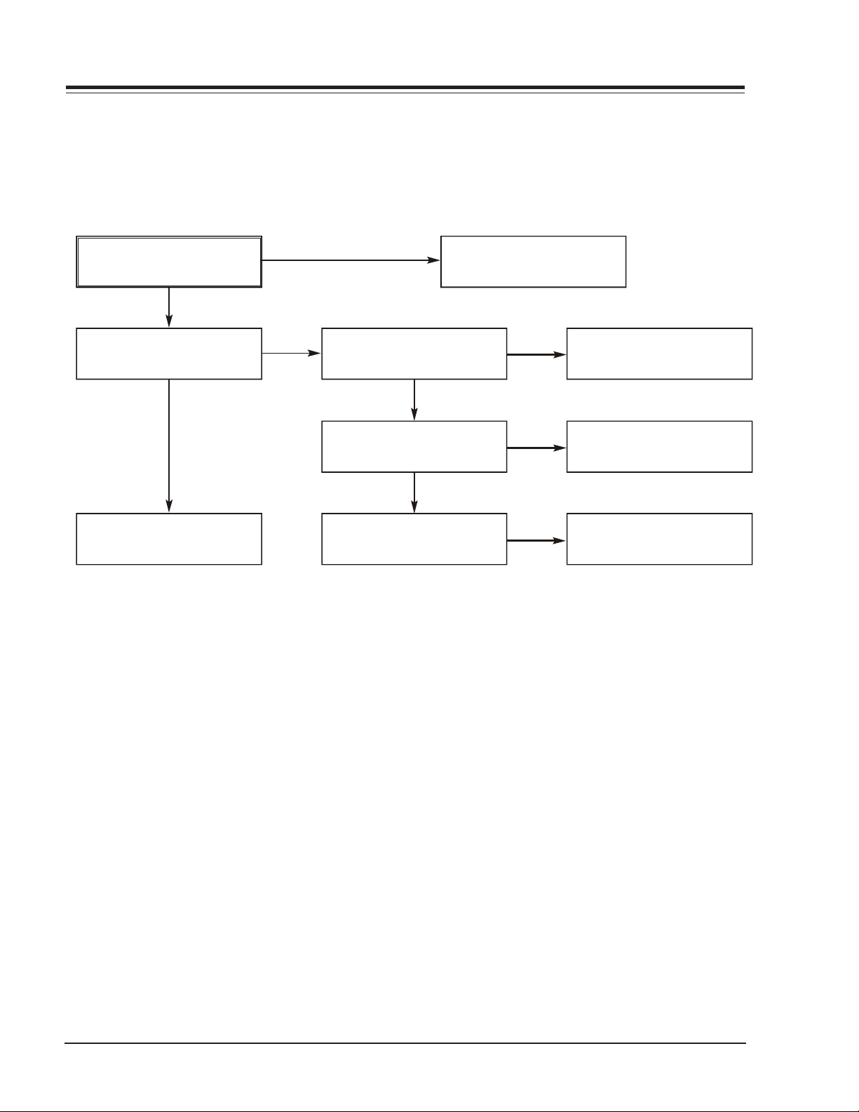
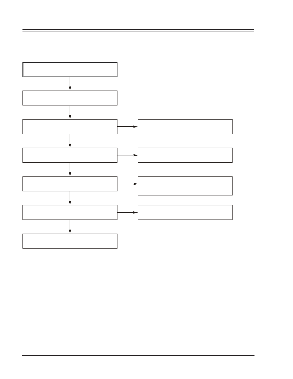
Page 29
1
COM Ci
TROUBLESHOOTING
ELECTRICAL
. µ-
A. Audio abnormal
rcuit
AUDIO ABNORMAL
Check Audio jack.
Check MPEG_CLK Signal
of MPEG part.
Refer to Audio part.
Refer to MPEG part.
Replace B/D.
YES
YES
YES
YES
(If OK)
(If OK)
(If OK)
(If OK)
B. Video abnormal
VIDEO ABNORMAL
Check Video jack.
Refer to Video part.
Refer to Encoder part.
Refer to MPEG part.
Replace B/D.
YES
YES
YES
YES
(If OK)
(If OK)
(If OK)
(If OK)
C. Open/Close abnormal
Check the connection of MD.
YES
OPEN/CLOSE ABNORMAL
connection of PMD03.
NO
Check IC501 Pins 13, 14.
Refer to SERVO part.
Check Front.
YES
Check the
YES
YES
(If OK)
NO
Reconnect it.
VR168 - 923-03485 3-17 D35E COMBO - ELECTRICAL
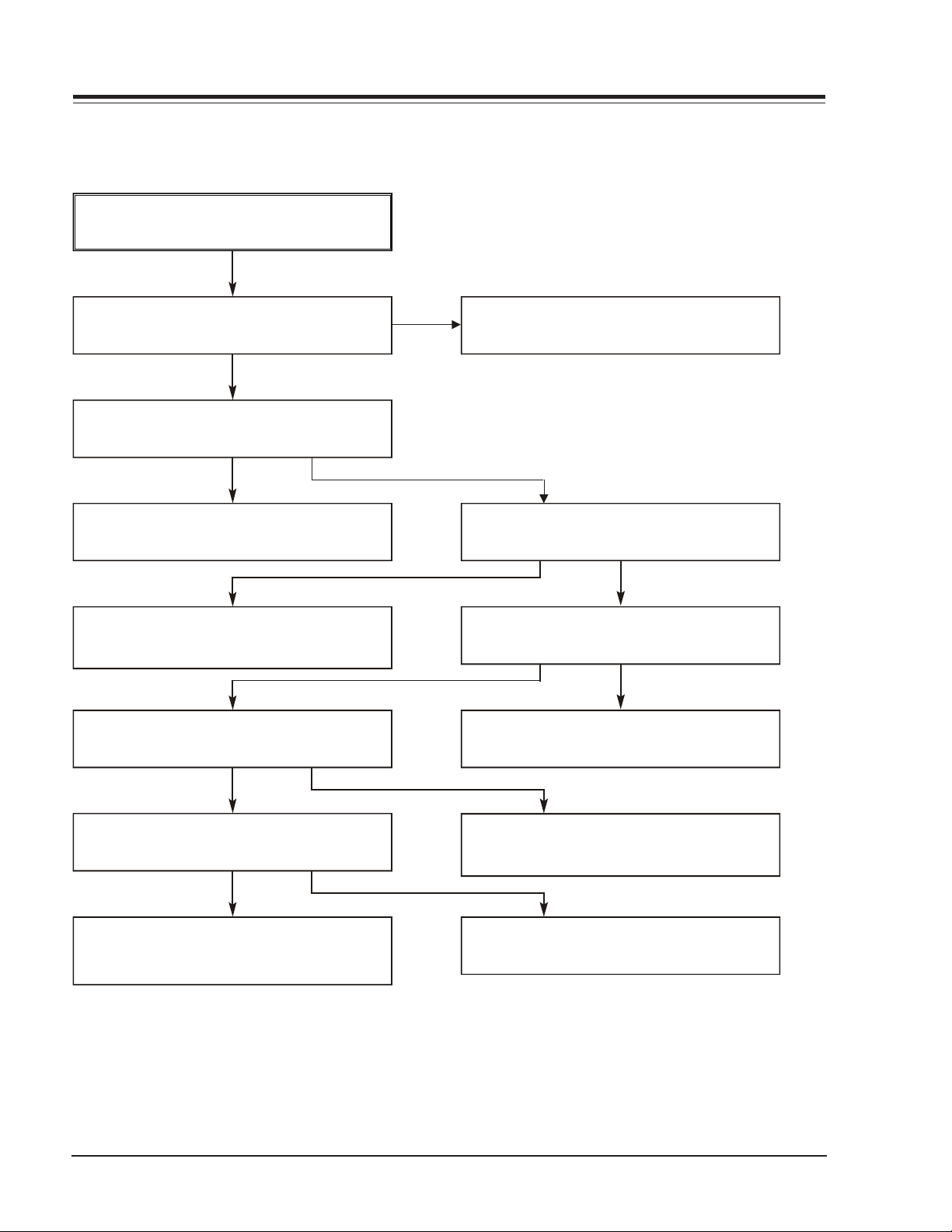
Page 30
DVD TROUBLESHOOTING (CONTINUED)
D. Picture abnormal
PICTURE ABNORMAL
Check the disc.
Refer to Servo part
If OK
Check MPEG_CLK Signal
of MPEG part
YES
Check DSP
ELECTRICAL
(If OK)
E. Disc Error
Refer to Servo part
YES
Check MPEG
YES
Replace B/D
DISC ERROR
Check Disc
YES
YES
(If OK)
(If OK)
(If OK)
(If OK)
Replace B/D
VR168 - 923-03485 3-18 D35E COMBO - ELECTRICAL
Page 31

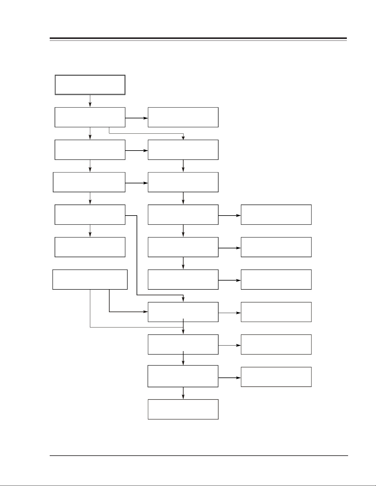
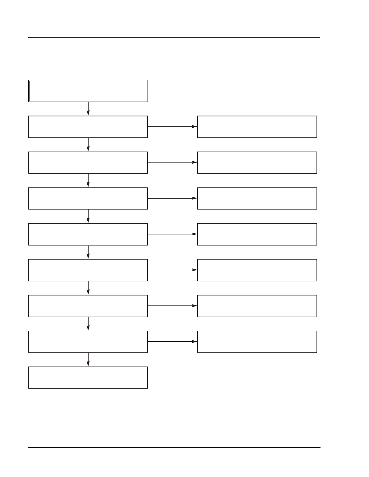
2
TROUBLESHOOTING (CONTINUED)
. MPEG Circuit
Power is on
ELECTRICAL
Check power & clock.
Does Logo appear
on the screen?
YES
Does the
moving picture of the DVD Disc
play on the screen
normally?
YES
NO
NO
YES
Check power & clock.
YES
Is MPEG data
signal normal?
YES
Is error signal normal?
NO
OK
NO
Check CD/DVD DSP
output signal.
OK
Check MPEG Decoder
input signal.
Check CD/DVD DSP
output signal.
OK
Check MPEG Decoder
input signal.
Does the
moving picture of the video
CD play on the screen
normally?
YES
Does the audio sound
output normally?
YES
END
VR168 - 923-03485 3-19 D35E COMBO - ELECTRICAL
NO
NO
Is MPEG data
signal normal?
YES
Is Clock normal?
YES
Does the audio
sound output from MPEG
decoder?
YES
NO
NO
Check CD/DVD DSP
output signal.
OK
Check MPEG Decoder
input signal.
Check clock signal
Check clock signal
Page 32

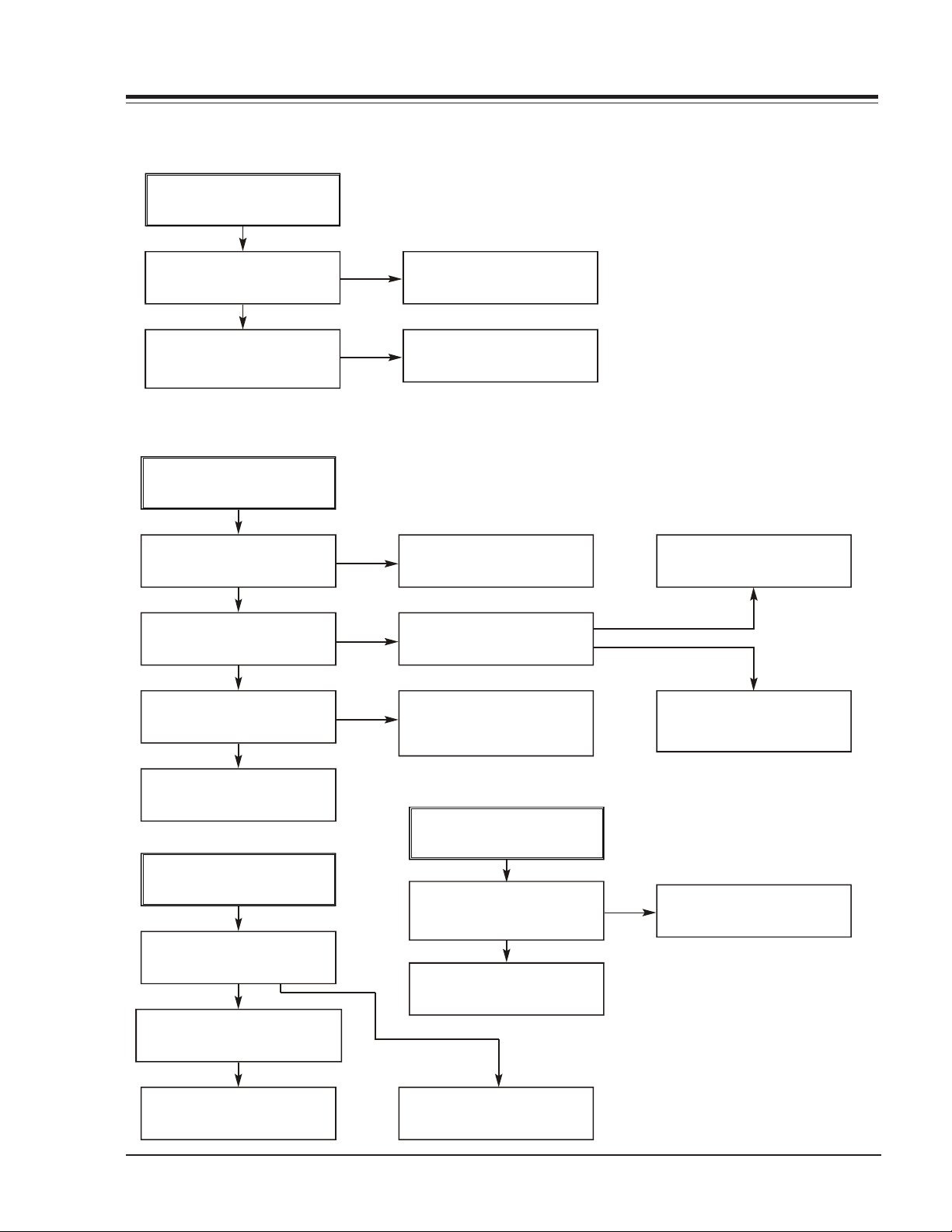
TROUBLESHOOTING (CONTINUED)
3. RF/Servo Circuit
A.
CHECK POINT(General)
ELECTRICAL
Does signal go "High"
to IC201 Pin194 when
power is on?
YES
Does signal pulse
input to IC201 Pins 58, 59
when power is on?
YES
Does
TTL pulse output to
IC201 Pins 140, 142?
Is IC201
Pins 83, 84, 88, 89 voltage
about 2.2V?
YES
NO
NO
NO NO
NO
Check "2.µ-COM Part".
Does
33.8688MHz clock input
to IC201 Pin 63?
YESYES
Replace IC201
(IC206 soldering or IC defect).
Check power circuit.
Replace X301 or IC304
(30MHz clock defect)
END
VR168 - 923-03485 3-20 D35E COMBO - ELECTRICAL
Page 33

TROUBLESHOOTING (CONTINUED)
No disc
B.
No disc
ELECTRICAL
Power on
Does tray open or close?
YES
NO
Check loading Part.
Push Pick-up to inner
track to the end by hand.
Does PMD03 Pin 13
change high to low?
YES
Pressing the open/close key,
check the voltage of IC2M1
Pins 22 change 0V to 5V
YES
Does the voltage change at
PMD03 Pins 1, 3 more than
2V on the basis of 3.8V?
YES
NO
NO
NO
DECK assembly is
defective. (Limit sw)
check µ-COM Part.
Replace IC2M1.
DECK assembly is defective
Does the pick-up slide
inner or outer track?
YES
Does the pick-up lens
move up and down?
YES
Slide the pick-up to
inner track.
END
VR168 - 923-03485 3-21 D35E COMBO - ELECTRICAL
NO
NO
Check SLED Driver output.
IC201 Pin 88 IC2M1 Pins 35, 36.
Check Focus Driver output.
(IC201 Pin 83, IC2M1 Pins 32, 33)
IC201 Pin 88 no output : IC201 is defective
IC2M1 Pin 19 no output : IC2M1 is defective
IC201 Pin 83 no output : IC201 is defective
IC2M1 Pins 24, 41 no output : IC2M1 is defective
Page 34

TROUBLESHOOTING (CONTINUED)
C
.
DISC IN
DISC IN
OPEN/CLOSE
FOCUS ON?
YES
NO
ELECTRICAL
Check the focus error
movingthe lens up and
down. (IC2A1 Pin 42)
YES
Fig.3. FOCUS ERROR waveform
NO
Check IC2A1 Pin 11,12,13,14
in DVD Mode
IC201 no output : Pick-up is defective.
Does the disc turn?
YES
IC201 Pin169 is "High"?
YES
Is OK the track jump.
Does the TTL level change
at IC201 Pin 78 and 132
moving the lens?
YES
Replace µ-COM or IC201.
Check IC2M1 Pin 18, PMD03
NO
Pin 6 turn when the IC2M1
Pin 21 is less than 2.2V.
NO
NO NO
Check A
NO
Check IC201 and IC2M1 when PMD03 Pin 6 is abnormal
Replace IC201.
Does the signal
pulse appear at IC2A1
Pins 39, 29?
IC2A1 is defective.
YES YES
Does the screen appear?
NO
YES
END
VR168 - 923-03485 3-22 D35E COMBO - ELECTRICAL
Video Part is defective.
Check "5.MPEG Circuit."
Check "7.OSD/Video Circuit."
Replace µ-COM part.
Page 35

TROUBLESHOOTING (CONTINUED)
CHECK A
ELECTRICAL
Check RF Eye-Pattern.
RF : 1.5-1.6V(IC2A1 Pin 57)
YES
Is the eye-pattern vivid?
YES YES YES
NO
Check IC2A1 Pins 5, 6, 7, 8.
NO NO N O
Does the
sawtooth waveform emit
at IC2A1 Pin 41?
Replace IC201.
No signal: Pick-up is defective
Does the 1.6V emit?
Check IC201 Pin84.
No signal at IC201 : IC201 is defective
Replace IC2A1.
• Check IC201 Pin 162.
• Check the clock at the IC201 Pins 28, 30.
END
VR168 - 923-03485 3-23 D35E COMBO - ELECTRICAL
• Both are normal : IC201 is defective
Page 36

- 3-24 -
Page 37

SECTION 4 Mechanical
VCR DECK MECHANISM
PART LOCATIONS
Top View
MECHANISM - VCR
2
7
10
1
31
14
15
8
Bottom View
6
3
4
9
5
11
18
16
17
19
19
12
33
13
15
T: Top, B:Bot
NOTES:
• When reassembling, perform the procedure in the
reverse order.
• When reassembling, confirm Mechanism and Mode
Switch Alignment Position (refer to Page 4-14)
VR168 - 923-03485 4-1 D35E COMBO - SERVICING
Page 38

MECHANISM - VCR
DRUM ASSEMBLY
1) Unplug the Drum FPC Connector.
2) Remove three Screws (S1) on the bottom side and
separate the Drum assembly.
3) Unhook (H1), (H2) and separate the Holder FPC and
Cap FPC. Also see figure (B1).
DRUM MOTOR
1) Remove two Screws (S2) and disassemble the Stator of the Drum Motor.
2) Remove two Screws (S3) and separate the Rotor of
the Drum Motor from the Drum Sub assembly.
NOTE: When reassembling, check to ascertain that Carbon
Brush is in position.
(S2)
(S2)
(S3)
(S3)
Fig.
Stator
Drum Motor
Rotor
B-1
Holder FPC
FPC
Drum
Reversed Direction
Cap
FPC
Carbon Brus h
Drum Sub Assembly
(A)
Drum FPC
(S1)
(S1)
(S1)
H2
H1
Holder FPC
Fig. A-1
VR168 - 923-03485 4-2 D35E COMBO - SERVICING
Page 39

MECHANISM - VCR
PLATE TOP (FIG. A-2-1)
1)To Remove, use a screwdriver to carefully free the
tabs at each end (B and B’ in the figure at right).
Rotate the plate upwards to free the slotted hooks
from the studs (C and C’ in the figure).
2) To replace, slide the hooks into position on the
studs (C and C’) and snap the Plate Top down into
place.
(B')
(C')
(C)
(B)
(H8)
(B')
Plate Top
Arm Assembly F/L
Lever Assembly S/W
Spring Lever S/W
(Fig. A-2-1)
(B)
A-2-6)
(Fig.
(Fig.
A-2-7)
Brackert Assembly L/D Motor
(C)
Holder Assembly CST
(E)
(C1)
(Fig.
A-2-2)
(C')
(D)
Chassis
Gear Assembly Rack F/L
(E')
Opener Door
(H6)
(A)
(Fig. A-2-3)
(B)
(Fig. A-2-5)
Fig. A-2
VR168 - 923-03485 4-3 D35E COMBO - SERVICING
Page 40

MECHANISM - VCR
HOLDER ASSEMBLY CST (FIG. A-2-2)
1) Move the Holder assembly CST in direction of arrow
and lift the left side through slot (D) .
2) Pull the right side of the Holder assembly CST from
the guided holes in the Chassis.
Gear Rack F/L
Holder assembly CST
(D)
Chassis
GUIDE CST (FIG.A-2-3)
BRACKET ASSEMBLY L/D MOTOR(FIG. A-2-4)
1) Unplug the Connector (C1).
2) Unhook three Hooks (H3,H4,H5) on the bottom of
the Chassis, lift up the Bracket assembly L/M and
disassemble the Bracket assembly L/D Motor.
(H4)
(H3)
(H5)
Bracket assemb ly L/M
Gear Drive
ARM ASSEMBLY F/L (FIG. A-2-6)
1) Rotate the Arm assembly F/L in the direction of the
arrow and remove the left side first.
2) Pull the Arm assembly F/L from the guided holes in
the Chassis.
LEVER ASSEMBLY S/W (FIG. A-2-7)
1) Hook the Spring Lever S/W on the Hook (H7) first
as shown below.
2) Unhook Hook (H8) in the left side of the Chassis
and remove the Lever assembly S/W.
Chassis
(H8)
(H7)
Spring Lever S/W
GEAR ASSEMBLY RACK F/L (FIG. A-2-5)
1) Move the Gear Assembly Rack F/L in the direction of
the arrow (A) and unhook Hook (H6), pulling back
in front.
2) Separate the Rear Rack F/L in the direction of the
arrow (B).
NOTE: When reassembling, align the Gear part of the Gear
Assembly Rack F/L with the Gear Drive as shown
in the following figure.
VR168 - 923-03485 4-4 D35E COMBO - SERVICING
Page 41

MECHANISM - VCR
ARM ASSEMBLY CLEANER (FIG. A-3-1)
1) Carefully pry tab “A” (see Fig. A-3-1) to clear the
embossed tab on the chassis. Turn the Arm Assembly Cleaner clockwise and lift it from the chassis.
HEAD F/E (FIG. A-3-2)
1) Carefully pry tab “A” (see Fig. A-3-2) to clear the
embossed tab on the chassis. Turn the Arm Assembly Cleaner counter-clockwise and lift it from the
chassis.
BASE ASSEMBLY A/C HEAD (FIG. A-3-3)
1) Remove Screw (S4) and lift the Base assembly A/C
Head up.
Arm Assembly
Cleaner
(Fig. A-3-1)
(A)
(S4)
Head F/E
(Fig.
A-3-2)
(A)
Chassis
Fig. A-3
Base Assembly A/C Head
A-3-3)
*(Fig.
VR168 - 923-03485 4-5 D35E COMBO - SERVICING
Page 42

Arm Assembly Tension
(Fig.
A-4-3)
Spring Tension
(H11)
MECHANISM - VCR
Reel S
A-4-4)
(Fig.
Spring TB
Brake Assembl y T
(Fig. A-4-1)
(Fig.
Spring RS
Reel T
A-4-4)
Brake Assembly RS
A-4-2)
(Fig.
(H12)
Base Tension
Chassis
BRAKE ASSEMBLY T (FIG. A-4-1)
1) Unhook Spring TB from Hook (H9) of the chassis.
2) Lift Brake assembly T.
BRAKE ASSEMBLY RS (FIG. A-4-2)
1) Unhook Spring RS from Hook (H10) of the
chassis.
2) Lift Brake assembly RS.
ARM ASSEMBLY TENSION (FIG. A-4-3)
1) Unhook the Spring Tension from Hook (H11) of the
Arm Assembly Tension.
2) Unhook Hook (H12) of the Base Tension and lift the
Arm Assembly Tension.
(H9)
(H10)
Fig. A-4
Spring Identification Chart
Spring TB
Spring RS
Spring Tension
REEL S / REEL T (FIG. A-4-4)
Reel S Reel T
VR168 - 923-03485 4-6 D35E COMBO - SERVICING
Page 43

MECHANISM - VCR
Opener Lid
(B)
(Fig. A-5-2)
Base Assembly P4
A-5-1)
(Fig.
(A)
(B)
Assembly
(Fig.
(C)
Arm
Pinch
A-5-3)
(C)
Arm T/up
(Fig.
A-5-5)
Lever T/up
(Fig.
A-5-4)
(H13)
(H13)
Chassis
Fig. A-5
BASE ASSEMBLY P4 (FIG. A-5-1)
1) Carefully pry up Tab (A) to clear the embossed tab on
the chassis.
2) Turn the Base assembly P4 counterclockwise and lift
it up.
17. OPENER LID (FIG. A-5-2)
1) Carefully pry up Tab (B) to clear the embossed tab on
the chassis.
2) Turn the Opener Lid clockwise and lift it up.
18. ARM ASSEMBLY PINCH (FIG. A-5-3)
Lift the Arm assembly Pinch up.
VR168 - 923-03485 4-7 D35E COMBO - SERVICING
LEVER T/UP (FIG. A-5-4)
ARM T/UP (FIG. A-5-5)
1) Unhook the Hook (H13) of the bottom Chassis and
lift the Lever T/up.
2) Lift the Arm T/up.
NOTE: When reassembling, confirm that the (C) portion
of the Arm assembly Pinch is inserted to the Chassis
Hole correctly as Fig. Place the Mechanism upsidedown.
Page 44

MECHANISM - VCR
BELT & MOTOR CAPSTAN (FIG. A-6-1/2)
1) Remove the Belt Capstan.
2) Remove the three Screws (S5) from the bottom of
the Chassis and lift the Motor Capstan.
LEVER F/R (FIG. A-6-3)
Unlock the Locking Tab (L1) as in Fig. A-6-3 and
lift the Lever F/R.
Brake Assembly Capstan
A-6-5)
(Fig.
(L1)
CLUTCH ASSEMBLY D35 (FIG. A-6-4)
BRAKE ASSEMBLY CAPSTAN (FIG. A-6-5)
Belt Capstan
(Fig. A-6-1)
Motor Capstan
A-6-2)
(Fig.
(L1)
Remove Washer (W1) and lift the Clutch assembly
D35.
Pull the Locking Tab (L2) back in the direction of
the arrow and lift it up.
Washer(W1)
Clutch Assembly D35
(Fig.
A-6-4)
(L2)
Lever F/R
(Fig.
A-6-3)
Chassis
(S5)
Fig. A-6
VR168 - 923-03485 4-8 D35E COMBO - SERVICING
Page 45

MECHANISM - VCR
GEAR DRIVE & CAM (FIG. A-7-1/2)
1) Remove Washer (W2) and lift the Gear Drive.
2) Unhook Hook (H14) of the Gear Cam and lift the
Gear Cam.
NOTE: When reassembling, align the Gear Drive Hole(A)
and the Gear Cam Hole(B) in a straight line after
the Gear Drive Hole(C) is aligned with the Chassis
Hole. (See Inset)
GEAR SECTOR (FIG. A-7-3)
Unhook Hook (H15) of the Base Loading fron the
bottom of the Chassis and lift the Gear Sector.
(H14)
Gear Cam Hole(B)
Gear Drive Hole(A)
(Fig.
PLATE SLIDER (FIG. A-7-4)
Lift the Plate Slider.
LEVER TENSION (FIG. A-7-5)
1) Unhook the (A) portion of the Lever Tension from
Hook (H16) of the Chassis.
2) Turn the Lever Tension counterclockwise and lift.
LEVER SPRING (FIG. A-7-6)
Unlock Locking Tab (L3) from the bottom of the
Chassis and lift the Lever Spring.
Gear Cam
A-7-2)
Washer (W2)
Gear Drive
A-7-1)
(Fig.
Gear Sector
A-7-3)
(Fig.
Plate Slider
(Fig. A-7-4)
Gear Drive Hole(C)
Fig. A-7
Chassis
(H15)
(H16 )
(A)
(L3)
Lever Tension
(Fig.
A-7-5)
Lever spring
(Fig.
A-7-6)
Base Loading
VR168 - 923-03485 4-9 D35E COMBO - SERVICING
Page 46

MECHANISM - VCR
GEAR ASSEMBLY P2/P3 (FIG. A-8-1/2)
1) Lift the Gear assembly P2.
2) Lift the Gear assembly P3.
NOTE: When reassembling, align the two Holes of the
Gear assembly P2 and P3 after aligning the Gear
Sector Hole(A) with the Plate Slider Hole(B) (see
the inset below).
BASE ASSEMBLY P2/P3 (FIG. A-8-3/4)
1) Move Base assembly P2 in the direction of the arrow
(A) along the slot in the Chassis and disassemble it
from the bottom side.
Gear assembly P2 Hole
Gear assembly P3 Hole
2) Move Base assembly P3 in the direction of the arrow
(B) along the slot in the Chassis and disassemble it
from the bottom side. Place the Mechanism face
down, or return to original position.
Gear Assembly P3
A-8-2)
(Fig.
Lever spring Boss
Gear sector Hole(A)
Plate sl ider Hole(B)
(B)
Chassis
Base Assembly P3
(Fig.
A-8-4)
Fig. A-8
Base Assembly P2
(Fig.
A-8-3)
Gear Assembly P2
(Fig. A-8-1)
(A)
VR168 - 923-03485 4-10 D35E COMBO - SERVICING
Page 47

MECHANISM - VCR
BASE LOADING (FIG. A-9-1)
1) Remove the Screw (S7).
2) Lift the Base Loading.
BASE TENSION (FIG. A-9-2)
1) Carefully pry up Tab (A) to clear the embossed tab on
the chassis.
2) Turn the Base Tension counterclockwise and lift.
Base Tension
(Fig.
A-9-2)
(A)
(S7)
Base Loading
(Fig. A-9-1)
(B) (C)
ARM ASSEMBLY IDLER (FIG. A-9-3)
Pinch (B) and (C) as shown in Fig. A-9-3, and lift.
NOTE: When disassembling, be careful not to catch part
(D) on the Chassis (See the Inset).
Arm Assembly Idler Jog
A-9-3)
(Fig.
(D)
Chassis
Fig. A-9
VR168 - 923-03485 4-11 D35E COMBO - SERVICING
Page 48

TOOLS NEEDED FOR SERVICE
MECHANISM - VCR
1. Cassette Torque meter
1. SRK-VHT-303(Not
SVC part)
4. Torque gauge adapto r
2.
Alignment tape
5. Post height adjusting driver 6. + Type driver
3. Torque gauge
3. 600g.Cm ATG
3.
VR168 - 923-03485 4-12 D35E COMBO - SERVICING
Page 49

VCR ALIGNMENT
ALIGNMENT POSITION CHECK
MECHANISM - VCR
Mechanism
Purpose: To determine if the Mechanism is in the correct Position when a Tape is ejected.
Test Equipment/ Fixture
1) Turn the Power S/W on and eject the Cassette by press-
the Eject Button.
ing
Remove the To p Cover and Plate Assembly Top, visual-
2)
check if the Gear Cam Hole is aligned with the
ly
Chassis
not, rotate the Shaft of the Loading Motor to either
3)
Clockwise
IF
below Fig. C-2.
as
Alignment Position Check
Test Conditions (Mechanism
Blank tape
Hole as below Fig. C-2.
Counterclockwise until the Alignment is
or
Condition)
Remove the Screw which holds the Deck Mechanism and
4)
Main Frame and confirm That the Gear Cam is aligned
with the Gear Drive as below in Fig. C-1(B).
5) Confirm that the Mode S/W on the Main P.C.Board is
aligned as below in Fig.C-1(B).
6) Remount the Deck Mechanism on the Main P.C.Board
and
check each operation.
Check Point
CHECK
DIAGRAM
Gear Cam
(C)
(B)
Mode S/W
TOM VIEW
BOT
TOP VIEW
Gear Drive
Gear Cam (o) and Gear Drive (o) groove alignment
Fig. C-1
Fig. C-2
VR168 - 923-03485 4-13 D35E COMBO - SERVICING
Page 50

MECHANISM - VCR
PREPARATION FOR ADJUSTMENT
(To set the Deck Mechanism to the Loading state with-
out inserting a Cassette Tape).
1) Unplug the Power Cord from the AC Outlet.
2) Disassemble the Top Cover and Plate Assembly Top.
3) Plug the Power Cord into the AC Outlet.
4) Turn the Power S/W on and push the Lever Stopper
of the Holder Assembly CST to the back for Loading
the Cassette without Tape.
CHECKING TORQUE
Purpose: To insure smooth Transport of the Tape during each Mode of Operation.
If
the Tape Transport is abnormal, then check the Torque as indicated by the chart below.
Cover the Holes of the End Sensors at both sides of
the Bracket Side (L) and Bracket Assembly Door to
prevent a light leak. Then the Deck Mechanism drives
to the Stop Mode. In this case, The Deck Mechanism can accept inputs of each mode, however the
Rewind and Review Operation can not be performed
for more than a few seconds because the Take-up
Reel Table is in the Stop State and the reel pulses
can not be detected.
Test Equipment/ Fixture
Torque Gauge (600g/cm ATG)
Torque Gauge Adaptor
Cassette To rq ue Meter
NOTE:
The
Values are measured by using a
Torque Gauge Adaptor with the
Cassette
Torque Meter
Test Conditions
(Mechanism
Play (FF) or Review (REW) Mode
Torque Gauge and
Torque Gauge a ffixed.
Condition)
Checking Method
Perform each Deck Mechanism Mode without
inserting
Preparation for Adjustment).
Read the Measurement of the Ta k e -u p or Supply
Reels
Attach the To r qu e Gauge Adaptor to the To r qu e
Gauge
Cassette Tape (Refer to above No.2
a
the Cassette To rq ue Meter(Fig. C-3-2).
on
and then read the Val ue
(Fig. C-3-1).
NOTE:
The
Torque reading to measure occurs when the Ta pe
abruptly
Mode,
changes direction from Fast Forward of Rewind
when quick bracking is applied to both Reels.
Torque Gauge (600g.cm ATG)
Torque Gauge
Torq ue
Gauge
Adaptor
Tab le
Reel
Fig. C-3-2
VR168 - 923-03485 4-14 D35E COMBO - SERVICING
Fig. C-3-1
Page 51

MECHANISM - VCR
GUIDE ROLLER HEIGHT ADJUSTMENT
Purpose: To regulate the Height of the Tape so that
the Bottom of the Tape runs along the Tape Guide Line
on the Lower Drum.
PRELIMINARY ADJUSTMENT
Test Equipment/ Fixture
Post Height Adjusting Driver
Play or Review Mode
Adjustment Procedure
1) Confirm that the Tape runs along the Tape Guide Line of
the Lower Drum.
2) If the Ta pe runs at the bottom of the Guide Line, turn the
Guide Roller Height Adjustment screw clockwise.
3) If it runs at the top, turn it counterclockwise.
4) Adjust the Height of the Guide Roller to be guided to the
Guide
Point
Line of the Lower Drum from the Starting and Ending
the Drum.
of
PRECISE ADJUSTMENT
Test Equipment/Fixture
Oscilloscope
Alignment
Post Height Adjusting
Driver
Ta p e
CH-1:PB RF Envelope
CH-2:NTSC: SW 30Hz
PAL: SW 25Hz
Head Switching Output
Point
Envelope Output
Point
RF
Adjustment Procedure
1 )Play an Alignment
Oscilloscope
Switching Output
Head
Trac kin g Control(in PB Mode) : Center Position(When
2
Adjustment is performed after the Drum Assembly
this
has
been replaced, set the
)
Output is Maximum).
RF
4
urn(Move) the
3 ) H e i g h t A d j u s t m e n t S c r e w : F l a t t e n t h e R F W a v e f o r m
Clockwise
( F i g . C - 4 - 2
)Check that any Drop of RF Output is uniform at the
5
) T
and End of the
Sta rt
NOTE
Ta p e after connecting the Probe of the
the RF Envelope Output
Te s t Point.
Test Point and
to
Tracking Control so that the
)
Tracking Control(in PB Mode)
and Counterclockwise.(Fig. C-4-3)
Waveform.
ADJUSTMENT DIAGRAM
Play an Alignment Ta p e
Waveform
.
Tracking
Diagrams
POST
P2
ADJUSTMENT
P3 POST
ADJUSTMENT
control at center
Connection Diagram
Adjustment Point
Guide Roller Height Adjustment
screws
Guide
the Supply and Ta ke -U p
on
Rollers.
Guide
Adjustment screw
Upper Flange
Guide
Retaining
Fig. C-4-1
Adjustment Point
Guide Roller Height
Adjustment
Tur n
the Roller Guide Height
Adjustment
to
flatten the waveform.
Fig. C-4-2
Tur n(M ove )
control
C-4-3
Fig.
Roller Height
Roller
Screw
Screws
Screw slightly
both directions
the tracking
to
OSCILLO SCOPE
w i l l
I f t h e a d j u s t m e n t i s e x c e s s i v e o r i n s u f f i c i e n t t h e t a p e
j a m o r f o l d
VR168 - 923-03485 4-15 D35E COMBO - SERVICING
.
RF ENVELOPE OUTPUT TEST POINT
HEAD SWITCHING OUTPUT TEST
POINT
Page 52

MECHANISM - VCR
AUDIO/CONTROL (A/C) HEAD ADJUSTMENT
Purpose: To insure that the Tape passes accurately over
the Audio and Control Tracks in exact Alignment in
both the Record and Playback Modes.
PRELIMINARY ADJUSTMENT
(Height and Tilt Adjustment)
Perform the Preliminary Adjustment when there is no
Audio Output Signal with the Alignment Tape.
Test Equipment/ Fixture
Blank Tape
Screw Driver(+) Type 5mm
Play the blank tape
Adjustment Procedure/Diagrams
1) Initially adjust the Base Assembly A/C Head as shown
Fig.
C-5-1 by using the Height Adjustment Screw (B).
2) Play
3) If
Blank Tape and observe if the Tape passes accu-
a
over the A/C Head without Ta pe Curling or Folding.
rately
Folding or Curling is occured then adjust the Tilt
Adjustment
ble
Fig. C-5-3.
Screw(C) while the Tape is running to resem-
Head Base
A/C
Fig. C-5-1
4) Reconfirm
onds.
NOTE
Ideal
A/C head height occurs, when the tape runs
between
head
core.
A/C Head
Adjustment Point
Til t Adjustment Screw (C)
Height Adjustment Screw (B)
Azimuth Adjustment Screw (A)
the Ta pe Path after Playback about 4~5 sec-
0.2~0.25mm above the bottom edge of the A/C
P4
Tap e
0.2~0.25mm
Tape
Fig. C-5-3
X-
Value Adjustment
Hole
Fixed
Screw
Azimuth
Screw(A)
Adjustment
ilt Adjustmen t
Screw(C)
T
Height Adjustment
Screw(B)
A/C Head Assembly
Fig. C-5-2
VR168 - 923-03485 4-16 D35E COMBO - SERVICING
Page 53

MECHANISM - VCR
CONFIRM OPERATION
Confirm that the Tape passes smoothly between the
Take-up Guide and Pinch Roller (using a Mirror or the
naked eye).
1) After completing Step 5-1. (Preliminary Adjustment), check that the Tape passes around the Takeup Guide and Pinch Roller without Folding or Curling at the Top or Bottom.
2) If Folding or Curling is observed at the Bottom of
the Take-up Guide, slowly turn the Tilt Adjustment
Screw (C) Clockwise.
PRECISE ADJUSTMENT
(Azimuth adjustment)
Tes t Equipment/ Fixture
Oscilloscope
Alignment Tape(SP)
Screw Driver(+) Type 5mm
Adjustment Procedure
1) Connect the Probe of the Oscilloscope to Audio Output
Jack.
2) Alternately
the Tilt Adjustment Screw (C) for Maximum Output of the
1Khz
Envelope
adjust the Azimuth Adjustment Screw (A)
and 7Khz segments, while maintaining the flattest
differential between the two Frequencies.
Connection Point
Audio output jack
3) If Folding or Curling is observed at the Top of it,
slowly turn the Tilt Adjustment Screw (C) counterclockwise.
NOTE: Check the RF Envelope after adjusting the A/C
Tes t Conditions
(Mechanism
Play an Alignment Tape
7KHz Sections
1KHz,
A:Maximum
Head, if the RF Waveform differs from Fig. C-5-4,
performs Precise Adjustment to flatten the RF
Waveform.
Condition)
1KHZ
Fig. C-5-4
Adjustment Point
7KHZ
B:Maximum
X-VALUE ADJUSTMENT
Purpose:
obtain compatibility with other VCR (VCP) Models.
To
Tes t Equipment/ Fixture
Oscilloscope
Alignment Tape (SP only)
Screw
CH-1: PB RF Envelope
CH-2: NTSC: SW 30Hz
Head Switching Output
Test Point
Point
PAL : SW 25Hz
Envelope Output
RF
Adjustment Procedure
1 ) Release the Automatic
Tracking to complete its Cycle.
)Loosen the Fixed Mounting Screw and move the Base
2
Assembly
Diagram
maximum
This
located
3
Tigh ten the Base Assembly A/C Head mounting Scre w.
A/C Head in the direction as shown in the
find the center of the peak that allows for the
Waveform Envelope.
method should allow the 31um Head to be centrally
to
over the 58um
Tracking to run long enough for
Tape
Track.
)
Te s t
Tes t Conditions
(Mechanism
Play an Alignment Ta p e
Condition)
Adjustment Diagram
X-Value Adjustment Hole
Azimuth Adjustment
Screw (A)
Connection Diagram
RF ENVELOPE OUTPUT TEST POINT
HEAD SWITCHING OUTPUT TEST POINT
Adjustment PointConnection Point
Groove at the
A/C
Left
Height Adjustment Screw (B)
Base
Right
Tilt Adjustment Screw (C)
OSCILLOSCOPE
CH-1
CH-2
VR168 - 923-03485 4-17 D35E COMBO - SERVICING
Page 54

MECHANISM - VCR
ADJUSTMENT AFTER REPLACING DRUM ASSEMBLY (VIDEO HEADS)
Purpose: To
Test Equipment/ Fixture
Oscilloscope
Alignment tapes
Blank Ta p e
Post Height Adjusting Driver
Screw Driver(+) Type 5mm
CH-1: PB RF Envelope
CH-2: NTSC: SW 30Hz
Head Switching Output
Test P o i nt
RF Envelope Output
Test P o i nt
Checking/Adjustment Procedure
Connection Point
PAL: SW 25Hz
Test Conditions
(Mechanism Condition)
Play the blank tape
Play an alignment tape
Connection Diagram
RF ENVELOPE OUTPUT TEST POINT
HEAD SWITCHING OUTPUT TEST
POINT
Waveform
V1/V MAX 0.7
V2/V MAX
RF ENVELOPE OUTPUT
0.8
TAPE TRAVEL AFTER REASSEMBLING DECK ASSEMBLY
AUDIO AND RF LOCKING TIME DURING PLAYBACK AND AFTER CUE OR REV (FF/REW)
Test Equipment
Test Equipment/ Fixture
Specification
Connection Points
Connection Points
Adjustment Points
Guide Roller Precise
Adjustment
Switching Point
Tracking Preset
X-Value
V1
V V2
Test Conditions
(Mechanism Condition)
OSCILLOSCOPE
CH1 CH2
Fig. C-7
Oscilloscope
Alignment tapes (with 6H
3kHz Color Bar Signal)
Stop Watch
Checking Procedure
Play an alignment tape then change the operating mode to
CUE or REV and confirm if the unit meets the above listed
specifications.
CHECK FOR TAPE CURLING OR JAMMING
Test Equipment/ Fixture
T-160 Tape
T-120 Tape
Checking Procedure
1) Confirm that the tape runs smoothly around the roller
guides, drum and A/C head assemblies while abruptly
changing operating modes from Play to CUE or REV.
This is to be checked at the begining, middle and end
sections of the cassette.
1) CUE is fast forward mode (FF)
2) REV is the rewind mode (REW)
3) Referenced to the Play mode
Specification
2) Confirm that the tape passes over the A/C head assem-
NOTES:
VCR(VCP) State
Run the CUE, REV play mode at the
beginning and the end of the tape.
bly as indicated by proper audio reproduction and proper tape counter performance.
VR168 - 923-03485 4-18 D35E COMBO - SERVICING
Page 55

MECHANISM - VCR
MAINTENANCE/INSPECTION PROCEDURE
CHECK BEFORE STARTING REPAIRS
The following faults can be remedied by cleaning and
oiling. Check the needed lubrication and the conditions
of cleanliness in the unit. Check with the customer to
find out how often the unit is used, and then determine
that the unit is ready for inspection and maintenance.
Check the following parts.
Phenomenon Inspection
Color beats Dirt on full-erase head o
Dirt on video head
Vertical or
Horizontal
Low volume,
Sound
Tape
Tap e
In
Review and
jitter
distorted
does not run.
slack
is
Dirt
video head
on
Dirt on pinch roller
Clutch Assembly D33K
Tor qu e
reduced
Cleaning Drum and
transport system
Replace-
ment
o
o
o
o
o
Fig. C-9-3
NOTE: If locations marked with o do not operate normally
after cleaning, check for wear and replace. See the
EXPLODED VIEWS at the end of this manual as well
as the above illustrations. See the Greasing (Page
4-22) for the sections to be lubricated and greased.
F/E Head
Video
A/C
Pinch
Capston
Belt
Head
Head
Roller
Fig. C-9-1 Top VIEW
Fig. C-9-2 BOTTOM VIEW
* No. (1)~(13) Indicates the
(3) F/E Head
Tape Path to be traveled from Supply Reel to Take-up Reel.
(6) Base Assembly P3
(7) A/C Head
(8) P4 Post
(10) Pinch Roller
(11) Ta ke- up Guide Post
(9) Capstan Shaft
(4)
Base
P2
y
)
( 5 ) D r u m A s s e m b l
( V i d e o H e a d
Assembly
(2)
Tension Post
(1) Supply Reel
(12) Take-up Reel
Fig.
C-9-3
Tape
Transport System
VR168 - 923-03485 4-19 D35E COMBO - SERVICING
Page 56

MECHANISM - VCR
REQUIRED MAINTENANCE
The recording density of a VCR(VCP) is much higher than
that of an audio tape recorder. VCR(VCP) components
must be very precise, at tolerances of 1/1000mm, to
ensure compatiblity with other VCRs. If any of these
components are worn or dirty, the symptoms will be the
same as if the part is defective. To ensure a good picture,
periodic inspection and maintenance, including
replacement of worn out parts and lubrication, is
necessary.
SCHEDULED MAINTENANCE
Schedules for maintenance and inspection are not fixed
because they vary greatly according to the way in which
the customer uses the VCR(VCP) and the environment in
which the VCR(VCP) is used. In general home use, a good
picture will be maintained if inspection and maintenance
is made every 1,000 hours. The table below shows the
relation between time used and inspection period.
Table 1
When
used
hour
hours
is
About 1
year
About
months
18
About
years
3
inspection
necessary
Average
hours
per
day
One
Two hours
Three
SUPPLIES REQUIRED FOR INSPECTION AND MAINTENCE
(1) Grease: Kanto G-311G (Blue) or equivalent
(2) Isopropyl Alcohol or equivalent
(3) Cleaning Patches
(4) Grease: Kanto G-381(Yellow)
MAINTENANCE PROCEDURE
CLEANING
1) Cleaning the video head. First use a cleaning tape.
If the dirt on the head is too stubborn to remove
by tape, use the cleaning patch. Coat the cleaning
patch with Isopropyl Alcohol. Touch the cleaning
patch to the head tip and gently turn
thehead(rotating cylinder) right and left. (Do not
move the cleaning patch vertically. Make sure that
only the buckskin on the cleaning patch comes
into contact with the head. Otherwise, the head
may be damaged.) Thoroughly dry the head. Then
run the test tape. If lsopropyl Alcohol remains on
the video head, the tape may be damaged when it
comes into contact with the head surface.
2) Clean the tape transport system and drive system,
etc, by wiping with a cleaning patch wetted with
Isporopyl Alcohol.
NOTES: It is the tape transport system which comes into
contact with the running tape. The drive system
consists of those parts which move the tape.
Make sure that during cleaning you do not touch
the tape transport system with the tip of a screw
driver and that no force that would cause deforming
or damage is applied to the system.
Drum
(Rotating
Cleaning
VR168 - 923-03485 4-20 D35E COMBO - SERVICING
Patch
Coat
With Isopropyl Alcohol
Touch
patch
turn
Fig. C-9-4
Head
this section of cleaning
the head tip and gently
the Drum (Rotating Cylinder)
to
Tip
Cylinder)
Page 57

MECHANISM - VCR
GREASING
1) Greasing guidelines. Apply grease, with a cleaning
patch. Do not use excessive grease as it may come
into contact with the tape transport or drive system. Wipe any excess and clean with a cleaning patch
wetted in Isopropyl Alcohol.
2) Periodic greasing. Grease specified locations every
5,000 hours.
2
1
1
Gear Part
Gear
2
Sector
6
Chassis
Top)
(
Gear
Cam
3
4
3
5
4
6
5
7
Chassis (Bottom)
8
Guide Rack F/L Gear Rack F/L
Base Loading Gear Drive
Guide Rail
Bracket Side (L)
Bracket
Assembly Door
VR168 - 923-03485 4-21 D35E COMBO - SERVICING
Page 58

GEAR , F/R
GEAR AY, P2 & P3
MECHANISM - VCR
VR168 - 923-03485 4-22 D35E COMBO - SERVICING
Page 59

VCR MECHANISM TROUBLESHOOTING
1.Deck Mechanism
A.
Auto REW doesn't work.
YES
Is the output of END sensor
of supply side "H":
more than 3.5V?
Or, less than 0.7V~1V?
NO
YES
MECHANISM - VCR
Is the voltage across IR LED
between 0.8~1.5V?
NO
Check syscon circuit.
B.
No F/R modes.
YES
Is the present mode,
F/R mode?
NO
NO
Is the Vcc voltage of
END sensor 5V?
YES
Replace END sensor
Replace LED
Is the mode SW assembled
correctly (refer to page 4-14)
NO
Check the syscon power.
YES
Does the Capstan Motor rotate?
YES
Do the T/Up and
Supply Reel rotate?
YES
Check syscon circuit.
VR168 - 923-03485 4-23 D35E COMBO - SERVICING
NO
YES
NO
Check servo, power circuits
YES
Replace the Capstan Motor
Page 60

C.
AUTO STOP.
(PLAY/CUE/REV)
MECHANISM - VCR
In Play/Cue/Rev is the pinch
roller in contact with the
capstan shaft.
YES
Are there T/up and
supply reel pulses.
YES
Check the Syscon, µ-COM.
D.
No cassette loading.
Insert the cassette.
NO
Replace Drum Motor.
NO
YES
NO
Check Servo, Syscon.
Replace Reel Sensor.
YES
NO
Does the lever Assembly
S/W work normally.
Check Holder Assembly CST.
YES
Is there variation for CST IN S/W
Output?
(In Tape with REC Tab
“L”-“H”-“L”)
(In Tape without REC Tab
“L”-“H”-“L”-“H”)
NO
NO
YES
YES
NO
Check Syscon Circuit.
VR168 - 923-03485 4-24 D35E COMBO - SERVICING
Check Syscon Circuit.
Page 61

E
.
In PB mode Tape Presence
not sensed.
MECHANISM - VCR
Is the Pinch Roller attached
to the Capstan Motor Shaft?
YES
Does the T/Up
Reel turn?
YES
Does the Capstan Motor turn?
YES
Does the Drum
Motor turn?
YES
Are there DPG,
DFG Pulses?
NO
NO
NO
Check Alignment positions
(page 4-14)
Is the Belt ok?
YES
Check the clutch and
the Idler Assembly.
Is the Voltage supplied to the
Capstan Motor Vcc1,Vcc2 each?
YES
Is the terminal voltage of Capstan
Motor supplied more than 4V?
NO
NO
Replace the Belt.
Check Syscon,
Circuit.
YES
Are the T/Up Supply
Reel Sensors ok?
YES
Replace the
Capstan Motor.
YES
Check Servo, Syscon.
Does the Capstan Motor turn?
NO
Is the Vcc voltage of the
Drum Motor normal?
NO
Check Syscon,
Circuit.
YES
Is the terminal voltage of the
Drum Motor more than 2.3V?
NO
Check Servo,
Power.
YES
Replace the
Drum Motor.
VR168 - 923-03485 4-25 D35E COMBO - SERVICING
Page 62

MECHANISM - VCR
2. Front Loading Mechanism
A.
Cassette cannot be inserted.
Does the Lever Assembly
Switch work?
YES
Is the Vcc of Main P.C.Board
YES
Is the voltage between
cassette switch and GND on
Main P.C.Board 5V??
YES
Check Mode switch location
and syscon circuit.
NO
NO
NO NO
Is the Lever Assembly Switch
Spring damaged or omitted?
YES
Does the CST IN Switch work
normally?
NO
YES
Check syscon circuit.
Check power circuit.
Is there a short circuit between cassette
switch and GND on main P.C.Board?
YES
Remove the short circuit part or
Replace the main P.C.Board.
NO
Replace or add the Lever
Assembly Switch Spring.
Replace CST IN Switch.
Replace CST IN Switch.
B.
Cassette will not eject.
NO
Does the L/D motor rotate in reverse?
Check L/D Motor or Drive IC.
YES
NO
Does the Lever Assembly Switch work?
Replace lever Assembly Switch.
YES
NO
Does the Arm Assembly F/L work normally?
Replace Arm Assembly F/L.
YES
NO
Does the Opener Door work?
VR168 - 923-03485 4-26 D35E COMBO - SERVICING
Replace the Opener Door.
Page 63

C.
MECHANISM - VCR
Cassette will not load.
Does the CST insert?
YES
Does the opener Lid work?
YES
Does the Gear Rack F/L work?
NO
NO
YES
Does the Opener Door work?
YES
Does the Arm Assembly F/L work?
YES
Does the L/D Motor work?
NO
NO
Replace the Opener Lid.
Replace the Rear Rack F/L.
Is the opener Door assembled correctly?
Replace the Arm Assembly F/L.
YES
Does the Holder Assembly Cassette
move the Arm Assembly F/L?
YES
Replace the Front Loading
Mechanism Assembly.
VR168 - 923-03485 4-27 D35E COMBO - SERVICING
NO
Check the power of L/D Motor.
NO
Is the Holder Assembly Cassette
assembled correctly?
Page 64

DVD DECK MECHANISM
TOP VIEW (WITHOUT TRAY)
MECHANISM - DVD
BOTTOM VIEW
2 Screws,
2 Locking Tabs
4 Screws,
1 Connector
1 Locking Tabs
1 Screw
1 Screw
1 Locking Tab
1 Locking Tab
1 Locking Tab
1 Hook
2Screw
2 Locking Tabs
4-1
4-1
4-1
4-1
4-1
4-2
4-3
4-3
4-3
4-3
4-3
4-4
4-4
4-4
4-4
4-4
4-4
4-4
TOP VIEW (WITH TRAY)
Note: The “Bottom” in the Disassembly column of the
Table indicates that the part should be disassembled from
the Bottom side.
VR168 - 923-03485 4-28 D35E COMBO - SERVICING
Page 65

MECHANISM - DVD
MECHANISM DISASSEMBLY
HOLDER CLAMP (FIG. 4-1)
1) Release 1 Screws (S1).
2) Unhook 2 Locking Tabs (L1).
3) Lift up the Holder Clamp and separate it from the
Base Main.
CLAMP ASSEMBLY DISC
1) Place the Clamp Assembly Disc as in Fig. (A)
2) Lift up the Clamp Assembly Disc in the direction of
the arrow (A).
3) Separate the Clamp Assembly Disc from the Holder
Clamp.
PLATE CLAMP
1) Turn the Plate Clamp counterclockwise and then
lift.
MAGNET CLAMP / CLAMP UPPER
TRAY DISC (FIG. 4-2)
1) Insert and push a Driver in the emergency eject hole
(A) at the right side, or put the Driver on the Lever
(B) of the Gear Emergency and pull the Lever (B) in
direction of arrow so that the Tray Disc is ejected
about 15~20mm.
2) Pull the Tray Disc until it is separated from the Base
Main completely.
Fig. 4-2
Fig. 4- 1
VR168 - 923-03485 4-29 D35E COMBO - SERVICING
Page 66

BASE ASSEMBLY SLED (FIG. 4-3)
1) Release 4 Screws (S2).
2) Disconnect the FFC Connector (C1)
GEAR ASSEMBLY FEED
Unhook the Locking Tab (L2) in the direction of
the arrow.
GEAR MIDDLE
GEAR ASSEMBLY RACK
Release the Scerw (S3)
RUBBER REAR (FIG. 4-3)
MECHANISM - DVD
(L2)
GEAR ASSEMBLY RACK
PICK UP
ASSEMBLY
GENE RAL
(C1)
(S2)
GEAR MIDDLE
(S3)
(S2)
PICK UP
MOTOR
GEAR
ASSEMBLY FEED
(S2)
RUBBER REAR
ASSEMBLY GENERAL
ASSEMBLY
(S2)
BASE PU(OUTSERT)
Fig. 4-3
VR168 - 923-03485 4-30 D35E COMBO - SERVICING
Page 67

MECHANISM - DVD
FRAME ASSEMBLY UP/DOWN
Note: Put the Base Main face down (Bottom Side)
1) Release the Screw (S4)
2) Unlock the Locking Tab (L3) in the direction of the
arrow and then lift up the Frame Assembly Up/Down to
separate it from the Base Main.
Note:
• When reassembling move the Guide Up/Down in direction of arrow (C) until it is positioned as Fig (C).
• When reassembling insert (A) portion of the Frame
Assembly Up/Down in the (B) portion of the Guide
Up/Down as Fig (B).
BELT LOADING(FIG. 4-4)
Note: Put the Base Assembly Main in original position (Top
Side)
GEAR PULLEY (FIG. 4-4)
1) Unlock the Locking Tab (L4) in the direction of the
arrow (B) and then separate the Gear Pulley from the
Base Main.
GEAR LOADING (FIG. 4-4)
GUIDE UP/DOWN (FIG. 4-4)
1) Move the Guide Up/Down in direction of arrow (A) as
in Fig.(A)
2) Push the Locking Tab (L5) down and then lift up the
Guide Up/Down to separate it from the Base Main.
Note: When reassembling place the Guide Up/Down as in
Fig (C) and move it in the direction of the arrow (B)
until it is locked by the Locking Tab (L5). And confirm
the Guide Up/Down as in Fig (A).
PWB ASSEMBLY LOADING
Note: Put the Base Main face down(Bottom Side)
1) Release 2 Screws(S5)
2) Disconnect the Loading Motor Connector from the
Hook (H1) on the Base Main.
3) Unlock 2 Locking Tabs(L6) and separate the PWB Assembly Loading from the Base Main.
BASE MAIN(FIG. 4-4)
Fig. 4-4
VR168 - 923-03485 4-31 D35E COMBO - SERVICING
Page 68

MECHANISM - DVD
Fig.11.
Adjusting Screen Display
DECK MECHANISM ADJUSTMENT
1) Insert Disc (Only Open/Close Key Pressing)
2) Wait Until the Sector Display is about 200,000
(Fig.11)
3) Adjust R-Skew adjusting Point until the Error rate
has minimum rate with L-wrench (3mm).
4) Adjust T-Skew Adjusting Point until the Error rate
has minimum rate.
5) Repeat No. 3, 4 adjusting procedure until the Error
rate have Minimum rate.
6) Error rate; SVC-3561 Disc=below 30 and TDV-533
Disc=below 100. If not, Please confirm Play ability
on screen.
You can watch the screen when pressing the Stop key
after the Adjusting is finished, Then perform Play and
Scan/Skip operation at Chapter1 and Chapter16 and
confirm screen condition, normal or abnormal.
• Please obtain the software for Adjusting through
our Global Cyber Service Center (GCSC).
• The location is http://biz.lgservice.com
• Web Site for End users
• Software updates
• Product : DVD Player
• Search.
Fig.12. Adjusting Method
VR168 - 923-03485 4-32 D35E COMBO - SERVICING
Page 69

COMPONENT PARTS
COMPONENT PARTS LIST
XBV243
NOTE: This list will enable you to easily determine the parts used on each Model, Chassis, or Assembly.
LOC PART# DESCRIPTION LOC PART# DESCRIPTION
The following information is for models in and out of
warranty. The XBV243 model is component level repair.
To Order Parts: call 1-888-3-ZENITH
fax 1-888-6-ZENITH
By Mail: ZENITH NATIONAL PARTS
SALES AND DISTRIBUTION CENTER
P O Box 240007
Huntsville, AL 35824-6407
Model Parts
276 4930R-0298A Holder, Shelf Front Right Panel Holder
285 3580R-T049C Door, Case Tray (Dc596M Evnt)
300 6410RAHK02D Power Cord Kj-10W/Nispt-2 (St-Hs
801 3835RM0052F Operator’S Guide Dc596M Aa1Uzz
900 6711R1P042D Remote Controller N6 Combo Dc596M Zen
A26 6721R-0324A DVD Deck Assy, Video Dp-4R (DVD)
A42 3501R-4942C Front Keyboard Left Assy Combi Keyboard Final
A43 3721R-F249E Panel Assy, Front Front (Dc596M Evnt W
A46 3501R-4938G Vcr PWB Board Assy Dc596M America Narro
A46-1 6871R-3198A DVD PWB (PCB) Assy Dc596M Na1Uzz Di Com
A49 3501R-4941C Front Keyboard Right Assy Lg Combi Keyboard F
DVD Deck Assy
12 5040R-0047B Rubber Damper (E2,5040H-1054A),Chunpoong
26 3390R-0005A Tray Disc
4 4930R-0171A Holder Clamp
9 4470R-0053A Gear Middle
A01 4861R-0014A Clamp Assy Disc (Dp-4) Di
A02 3041R-0059A Base Assy Sub, Main (DVD+Vcr)
A03 3041R-0060A Base Assy Sub,Sled (Dp-4V , DVD
DVD Main PWB
C201 0CH1104K942 Cap, Fixed Ceramic, 0.1Uf 50V 80%,-20%
C203 0CH1104K942 Cap, Fixed Ceramic, 0.1Uf 50V 80%,-20%
C204 0CH1104K942 Cap, Fixed Ceramic, 0.1Uf 50V 80%,-20%
C205 0CH1104K942 Cap, Fixed Ceramic, 0.1Uf 50V 80%,-20%
C206 0CH1104K942 Cap, Fixed Ceramic, 0.1Uf 50V 80%,-20%
C207 0CH1104K942 Cap, Fixed Ceramic, 0.1Uf 50V 80%,-20%
C208 0CE4764F638 Cap, Fixed Electro, 47Uf 16V 20%
C209 0CH1104K942 Cap, Fixed Ceramic, 0.1Uf 50V 80%,-20%
C210 0CH1104K942 Cap, Fixed Ceramic, 0.1Uf 50V 80%,-20%
C221 0CH1104K942 Cap, Fixed Ceramic, 0.1Uf 50V 80%,-20%
C222 0CH1104K942 Cap, Fixed Ceramic, 0.1Uf 50V 80%,-20%
C223 0CH1104K942 Cap, Fixed Ceramic, 0.1Uf 50V 80%,-20%
C224 0CH1104K942 Cap, Fixed Ceramic, 0.1Uf 50V 80%,-20%
C226 0CH1104K942 Cap, Fixed Ceramic, 0.1Uf 50V 80%,-20%
C227 0CH1104K942 Cap, Fixed Ceramic, 0.1Uf 50V 80%,-20%
C228 0CH1104K942 Cap, Fixed Ceramic, 0.1Uf 50V 80%,-20%
C229 0CH1104K942 Cap, Fixed Ceramic, 0.1Uf 50V 80%,-20%
C232 0CE1064F638 Cap, Fixed Electro, 10Uf 16V 20%
C237 0CH1104K942 Cap, Fixed Ceramic, 0.1Uf 50V 80%,-20%
C238 0CH1104K942 Cap, Fixed Ceramic, 0.1Uf 50V 80%,-20%
C239 0CH1104K942 Cap, Fixed Ceramic, 0.1Uf 50V 80%,-20%
C240 0CH1222K562 Cap, Fixed Ceramic, 2200Pf 50V 10%
C241 0CH1104K942 Cap, Fixed Ceramic, 0.1Uf 50V 80%,-20%
C242 0CH1104K942 Cap, Fixed Ceramic, 0.1Uf 50V 80%,-20%
C245 0CH1104K942 Cap, Fixed Ceramic, 0.1Uf 50V 80%,-20%
C250 0CH1104K942 Cap, Fixed Ceramic, 0.1Uf 50V 80%,-20%
C255 0CH1104K942 Cap, Fixed Ceramic, 0.1Uf 50V 80%,-20%
C256 0CH1104K942 Cap, Fixed Ceramic, 0.1Uf 50V 80%,-20%
C257 0CH1104K942 Cap, Fixed Ceramic, 0.1Uf 50V 80%,-20%
C258 0CH1104K942 Cap, Fixed Ceramic, 0.1Uf 50V 80%,-20%
C260 0CH4100K112 Cap, Fixed Ceramic, (High Di) 10Pf 50V
C270 0CE1064F638 Cap, Fixed Electro, 10Uf 16V 20%
C271 0CE1064F638 Cap, Fixed Electro, 10Uf 16V 20%
C272 0CE4764F638 Cap, Fixed Electro, 47Uf 16V 20%
C273 0CH1225F944 Cap, Fixed Ceramic, 2.2Uf 16V 80%,-20%
C274 0CE4764F638 Cap, Fixed Electro, 47Uf 16V 20%
C275 0CE1064F638 Cap, Fixed Electro, 10Uf 16V 20%
C276 0CE1064F638 Cap, Fixed Electro, 10Uf 16V 20%
C277 0CE1064F638 Cap, Fixed Electro, 10Uf 16V 20%
C278 0CE1064F638 Cap, Fixed Electro, 10Uf 16V 20%
C279 0CE1064F638 Cap, Fixed Electro, 10Uf 16V 20%
C280 0CE1064F638 Cap, Fixed Electro, 10Uf 16V 20%
C281 0CE1064F638 Cap, Fixed Electro, 10Uf 16V 20%
C284 0CE4764F638 Cap, Fixed Electro, 47Uf 16V 20%
C285 0CH1104K942 Cap, Fixed Ceramic, 0.1Uf 50V 80%,-20%
C286 0CH4180K412 Cap, Fixed Ceramic, (High Di) 18Pf 50V 5%
C287 0CH4180K412 Cap, Fixed Ceramic, (High Di) 18Pf 50V 5%
C288 0CH1104K942 Cap, Fixed Ceramic, 0.1Uf 50V 80%,-20%
C289 0CH1104K942 Cap, Fixed Ceramic, 0.1Uf 50V 80%,-20%
C2A0 0CH1104K942 Cap, Fixed Ceramic, 0.1Uf 50V 80%,-20%
C2A1 0CH1104K942 Cap, Fixed Ceramic, 0.1Uf 50V 80%,-20%
C2A2 0CH1222K562 Cap, Fixed Ceramic, 2200Pf 50V 10%
C2A3 0CH1104K942 Cap, Fixed Ceramic, 0.1Uf 50V 80%,-20%
C2A4 0CH1104K942 Cap, Fixed Ceramic, 0.1Uf 50V 80%,-20%
C2A5 0CH1104K942 Cap, Fixed Ceramic, 0.1Uf 50V 80%,-20%
C2A6 0CH1104K942 Cap, Fixed Ceramic, 0.1Uf 50V 80%,-20%
C2A7 0CH1104K942 Cap, Fixed Ceramic, 0.1Uf 50V 80%,-20%
C2A8 0CH1104K942 Cap, Fixed Ceramic, 0.1Uf 50V 80%,-20%
C2A9 0CH1104K942 Cap, Fixed Ceramic, 0.1Uf 50V 80%,-20%
C2B0 0CH1104K942 Cap, Fixed Ceramic, 0.1Uf 50V 80%,-20%
C2B1 0CH1104K942 Cap, Fixed Ceramic, 0.1Uf 50V 80%,-20%
C2B2 0CH1104K942 Cap, Fixed Ceramic, 0.1Uf 50V 80%,-20%
C2B3 0CH1473H942 Cap, Fixed Ceramic, 0.047Uf 25V 80%,-20%
C2B4 0CH4561K512 Cap, Fixed Ceramic, (High Di) 560Pf 50V 10%
C2B5 0CH4561K512 Cap, Fixed Ceramic, (High Di) 560Pf 50V 10%
C2B6 0CH1333K562 Cap, Fixed Ceramic, 0.033Uf 50V 10%
C2B7 0CH1333K562 Cap, Fixed Ceramic, 0.033Uf 50V 10%
C2B8 0CH1104K942 Cap, Fixed Ceramic, 0.1Uf 50V 80%,-20%
C2B9 0CH1104K942 Cap, Fixed Ceramic, 0.1Uf 50V 80%,-20%
C2C0 0CH4221K412 Cap, Fixed Ceramic, (High Di) 220Pf 50V 5%
C2C1 0CH1222K562 Cap, Fixed Ceramic, 2200Pf 50V 10%
C2C2 0CH1222K562 Cap, Fixed Ceramic, 2200Pf 50V 10%
C2C3 0CH1222K562 Cap, Fixed Ceramic, 2200Pf 50V 10%
C2C4 0CH1222K562 Cap, Fixed Ceramic, 2200Pf 50V 10%
C2C5 0CH1104K942 Cap, Fixed Ceramic, 0.1Uf 50V 80%,-20%
VR168 - 923-03485 5-1 D35E COMBO - CHASSIS
Page 70

COMPONENT PARTS LIST
XBV243
NOTE: This list will enable you to easily determine the parts used on each Model, Chassis, or Assembly.
LOC PART# DESCRIPTION LOC PART# DESCRIPTION
C2C6 0CH1472K562 Cap, Fixed Ceramic, 4700Pf 50V 10%
C2C7 0CH1472K562 Cap, Fixed Ceramic, 4700Pf 50V 10%
C2C8 0CH4330K412 Cap, Fixed Ceramic, (High Di) 33Pf 50V 5%
C2C9 0CH4330K412 Cap, Fixed Ceramic, (High Di) 33Pf 50V 5%
C2D0 0CH1104K942 Cap, Fixed Ceramic, 0.1Uf 50V 80%,-20%
C2D1 0CE4764F638 Cap, Fixed Electro, 47Uf 16V 20%
C2D2 0CE4764F638 Cap, Fixed Electro, 47Uf 16V 20%
C2D3 0CE4764F638 Cap, Fixed Electro, 47Uf 16V 20%
C2D4 0CE4764F638 Cap, Fixed Electro, 47Uf 16V 20%
C2D5 0CE1064F638 Cap, Fixed Electro, 10Uf 16V 20%
C2D6 0CH1104K942 Cap, Fixed Ceramic, 0.1Uf 50V 80%,-20%
C2D7 0CH1104K942 Cap, Fixed Ceramic, 0.1Uf 50V 80%,-20%
C2E1 0CH1182K562 Cap, Fixed Ceramic, 1800Pf 50V 10%
C2M1 0CH1104K942 Cap, Fixed Ceramic, 0.1Uf 50V 80%,-20%
C2M2 0CH1104K942 Cap, Fixed Ceramic, 0.1Uf 50V 80%,-20%
C2M3 0CE2276F638 Cap, Fixed Electro, 220Uf 16V 20%
C2M4 0CE1064F638 Cap, Fixed Electro, 10Uf 16V 20%
C2M5 0CH1104K942 Cap, Fixed Ceramic, 0.1Uf 50V 80%,-20%
C2M6 0CH1104K942 Cap, Fixed Ceramic, 0.1Uf 50V 80%,-20%
C2M7 0CH1104K942 Cap, Fixed Ceramic, 0.1Uf 50V 80%,-20%
C2M8 0CH1104K942 Cap, Fixed Ceramic, 0.1Uf 50V 80%,-20%
C2M9 0CH1223K942 Cap, Fixed Ceramic, 0.022Uf 50V 80%,-20%
C2N1 0CH1472K562 Cap, Fixed Ceramic, 4700Pf 50V 10%
C2N2 0CH1103K562 Cap, Fixed Ceramic, 0.01Uf 50V 10%
C2N3 0CH1682K562 Cap, Fixed Ceramic, 6800Pf 50V 10%
C2N4 0CH1104K942 Cap, Fixed Ceramic, 0.1Uf 50V 80%,-20%
C2N5 0CH1104K942 Cap, Fixed Ceramic, 0.1Uf 50V 80%,-20%
C2N6 0CH1225F944 Cap, Fixed Ceramic, 2.2Uf 16V 80%,-20%
C301 0CE1064F638 Cap, Fixed Electro, 10Uf 16V 20%
C302 0CE1064F638 Cap, Fixed Electro, 10Uf 16V 20%
C303 0CH1104K942 Cap, Fixed Ceramic, 0.1Uf 50V 80%,-20%
C304 0CH1104K942 Cap, Fixed Ceramic, 0.1Uf 50V 80%,-20%
C305 0CH1104K942 Cap, Fixed Ceramic, 0.1Uf 50V 80%,-20%
C306 0CH1104K942 Cap, Fixed Ceramic, 0.1Uf 50V 80%,-20%
C307 0CH1104K942 Cap, Fixed Ceramic, 0.1Uf 50V 80%,-20%
C308 0CH1104K942 Cap, Fixed Ceramic, 0.1Uf 50V 80%,-20%
C309 0CH1104K942 Cap, Fixed Ceramic, 0.1Uf 50V 80%,-20%
C310 0CH1104K942 Cap, Fixed Ceramic, 0.1Uf 50V 80%,-20%
C311 0CH1104K942 Cap, Fixed Ceramic, 0.1Uf 50V 80%,-20%
C312 0CH1104K942 Cap, Fixed Ceramic, 0.1Uf 50V 80%,-20%
C313 0CH1104K942 Cap, Fixed Ceramic, 0.1Uf 50V 80%,-20%
C314 0CH1104K942 Cap, Fixed Ceramic, 0.1Uf 50V 80%,-20%
C315 0CH1104K942 Cap, Fixed Ceramic, 0.1Uf 50V 80%,-20%
C316 0CH1104K942 Cap, Fixed Ceramic, 0.1Uf 50V 80%,-20%
C317 0CH1104K942 Cap, Fixed Ceramic, 0.1Uf 50V 80%,-20%
C318 0CH1104K942 Cap, Fixed Ceramic, 0.1Uf 50V 80%,-20%
C319 0CH1104K942 Cap, Fixed Ceramic, 0.1Uf 50V 80%,-20%
C320 0CH1104K942 Cap, Fixed Ceramic, 0.1Uf 50V 80%,-20%
C321 0CH1104K942 Cap, Fixed Ceramic, 0.1Uf 50V 80%,-20%
C322 0CH1104K942 Cap, Fixed Ceramic, 0.1Uf 50V 80%,-20%
C323 0CH1104K942 Cap, Fixed Ceramic, 0.1Uf 50V 80%,-20%
C324 0CH1104K942 Cap, Fixed Ceramic, 0.1Uf 50V 80%,-20%
C325 0CH1225F944 Cap, Fixed Ceramic, 2.2Uf 16V 80%,-20%
C326 0CH1104K942 Cap, Fixed Ceramic, 0.1Uf 50V 80%,-20%
C327 0CH1225F944 Cap, Fixed Ceramic, 2.2Uf 16V 80%,-20%
C328 0CE1064F638 Cap, Fixed Electro, 10Uf 16V 20%
C329 0CH1104K942 Cap, Fixed Ceramic, 0.1Uf 50V 80%,-20%
C330 0CH1104K942 Cap, Fixed Ceramic, 0.1Uf 50V 80%,-20%
C331 0CH1104K942 Cap, Fixed Ceramic, 0.1Uf 50V 80%,-20%
C332 0CH1104K942 Cap, Fixed Ceramic, 0.1Uf 50V 80%,-20%
C333 0CH1104K942 Cap, Fixed Ceramic, 0.1Uf 50V 80%,-20%
C334 0CH1104K942 Cap, Fixed Ceramic, 0.1Uf 50V 80%,-20%
C335 0CE1064F638 Cap, Fixed Electro, 10Uf 16V 20%
C336 0CH1104K942 Cap, Fixed Ceramic, 0.1Uf 50V 80%,-20%
C337 0CE1064F638 Cap, Fixed Electro, 10Uf 16V 20%
C338 0CH1104K942 Cap, Fixed Ceramic, 0.1Uf 50V 80%,-20%
C339 0CH1104K942 Cap, Fixed Ceramic, 0.1Uf 50V 80%,-20%
C340 0CH1103K562 Cap, Fixed Ceramic, 0.01Uf 50V 10%
C341 0CH1103K562 Cap, Fixed Ceramic, 0.01Uf 50V 10%
C343 0CE2274C638 Cap, Fixed Electro, 220Uf 6.3V 20%
C344 0CH1104K942 Cap, Fixed Ceramic, 0.1Uf 50V 80%,-20%
C345 0CH1104K942 Cap, Fixed Ceramic, 0.1Uf 50V 80%,-20%
C346 0CH1104K942 Cap, Fixed Ceramic, 0.1Uf 50V 80%,-20%
C347 0CH1104K942 Cap, Fixed Ceramic, 0.1Uf 50V 80%,-20%
C348 0CH1104K942 Cap, Fixed Ceramic, 0.1Uf 50V 80%,-20%
C349 0CH1104K942 Cap, Fixed Ceramic, 0.1Uf 50V 80%,-20%
C380 0CH1104K942 Cap, Fixed Ceramic, 0.1Uf 50V 80%,-20%
C382 0CH4100K112 Cap, Fixed Ceramic, (High Di) 10Pf 50V
C391 0CH1104K942 Cap, Fixed Ceramic, 0.1Uf 50V 80%,-20%
C392 0CH1103K562 Cap, Fixed Ceramic, 0.01Uf 50V 10%
C393 0CH1104K942 Cap, Fixed Ceramic, 0.1Uf 50V 80%,-20%
C394 0CH1104K942 Cap, Fixed Ceramic, 0.1Uf 50V 80%,-20%
C3K1 0CH1104K942 Cap, Fixed Ceramic, 0.1Uf 50V 80%,-20%
C3K2 0CH4120K412 Cap, Fixed Ceramic, (High Di) 12Pf 50V 5%
C3K3 0CH4150K412 Cap, Fixed Ceramic, (High Di) 15Pf 50V 5%
C403 0CH1103K562 Cap, Fixed Ceramic, 0.01Uf 50V 10%
C405 0CE4774C638 Cap, Fixed Electro, 470Uf 6.3V 20%
C406 0CH1103K562 Cap, Fixed Ceramic, 0.01Uf 50V 10%
C407 0CE2264F638 Cap, Fixed Electro, 22Uf 16V 20%
C408 0CE1064F638 Cap, Fixed Electro, 10Uf 16V 20%
C409 0CE4774C638 Cap, Fixed Electro, 470Uf 6.3V 20%
C410 0CE2264F638 Cap, Fixed Electro, 22Uf 16V 20%
C411 0CH1102K512 Cap, Fixed Ceramic, 1000Pf 50V 10%
C412 0CH4101K412 Cap, Fixed Ceramic, (High Di) 100Pf 50V 5%
C413 0CE1064F638 Cap, Fixed Electro, 10Uf 16V 20%
C414 0CH1103K562 Cap, Fixed Ceramic, 0.01Uf 50V 10%
C415 0CE1064F638 Cap, Fixed Electro, 10Uf 16V 20%
C416 0CH1102K512 Cap, Fixed Ceramic, 1000Pf 50V 10%
C417 0CH4101K412 Cap, Fixed Ceramic, (High Di) 100Pf 50V 5%
C418 0CH1392K562 Cap, Fixed Ceramic, 3900Pf 50V 10%
C419 0CE2264F638 Cap, Fixed Electro, 22Uf 16V 20%
C420 0CH1392K562 Cap, Fixed Ceramic, 3900Pf 50V 10%
C421 0CE2264F638 Cap, Fixed Electro, 22Uf 16V 20%
C422 0CE1064F638 Cap, Fixed Electro, 10Uf 16V 20%
C424 0CH1103K562 Cap, Fixed Ceramic, 0.01Uf 50V 10%
C425 0CH1103K562 Cap, Fixed Ceramic, 0.01Uf 50V 10%
C428 0CH1103K562 Cap, Fixed Ceramic, 0.01Uf 50V 10%
C429 0CE4764F638 Cap, Fixed Electro, 47Uf 16V 20%
C430 0CE4764F638 Cap, Fixed Electro, 47Uf 16V 20%
C501 0CH1104K942 Cap, Fixed Ceramic, 0.1Uf 50V 80%,-20%
C502 0CE1064F638 Cap, Fixed Electro, 10Uf 16V 20%
C503 0CH1104K942 Cap, Fixed Ceramic, 0.1Uf 50V 80%,-20%
VR168 - 923-03485 5-2 D35E COMBO - CHASSIS
Page 71

COMPONENT PARTS LIST
XBV243
NOTE: This list will enable you to easily determine the parts used on each Model, Chassis, or Assembly.
LOC PART# DESCRIPTION LOC PART# DESCRIPTION
C504 0CH1104K942 Cap, Fixed Ceramic, 0.1Uf 50V 80%,-20%
C505 0CH1104K942 Cap, Fixed Ceramic, 0.1Uf 50V 80%,-20%
C507 0CH1104K942 Cap, Fixed Ceramic, 0.1Uf 50V 80%,-20%
C508 0CE1064F638 Cap, Fixed Electro, 10Uf 16V 20%
C509 0CH1104K942 Cap, Fixed Ceramic, 0.1Uf 50V 80%,-20%
C510 0CH1104K942 Cap, Fixed Ceramic, 0.1Uf 50V 80%,-20%
C511 0CH1104K942 Cap, Fixed Ceramic, 0.1Uf 50V 80%,-20%
C512 0CH1104K942 Cap, Fixed Ceramic, 0.1Uf 50V 80%,-20%
C513 0CH1104K942 Cap, Fixed Ceramic, 0.1Uf 50V 80%,-20%
C514 0CE1064F638 Cap, Fixed Electro, 10Uf 16V 20%
C515 0CE2274C638 Cap, Fixed Electro, 220Uf 6.3V 20%
C516 0CH1225F944 Cap, Fixed Ceramic, 2.2Uf 16V 80%,-20%
C517 0CH1225F944 Cap, Fixed Ceramic, 2.2Uf 16V 80%,-20%
C518 0CH1104K942 Cap, Fixed Ceramic, 0.1Uf 50V 80%,-20%
C519 0CH1225F944 Cap, Fixed Ceramic, 2.2Uf 16V 80%,-20%
C520 0CH1104K942 Cap, Fixed Ceramic, 0.1Uf 50V 80%,-20%
C521 0CH1105D942 Cap, Fixed Ceramic, 1Uf 10V 80%,-20%
C522 0CH1105D942 Cap, Fixed Ceramic, 1Uf 10V 80%,-20%
C523 0CH4221K412 Cap, Fixed Ceramic, (High Di) 220Pf 50V 5%
C525 0CH4221K412 Cap, Fixed Ceramic, (High Di) 220Pf 50V 5%
C526 0CH4221K412 Cap, Fixed Ceramic, (High Di) 220Pf 50V 5%
C531 0CH4221K412 Cap, Fixed Ceramic, (High Di) 220Pf 50V 5%
C532 0CH4221K412 Cap, Fixed Ceramic, (High Di) 220Pf 50V 5%
C534 0CH4560K412 Cap, Fixed Ceramic, (High Di) 56Pf 50V 5%
C536 0CE2274C638 Cap, Fixed Electro, 220Uf 6.3V 20%
C602 0CE1054K638 Cap, Fixed Electro, 1Uf 50V 20%
C603 0CH1104K942 Cap, Fixed Ceramic, 0.1Uf 50V 80%,-20%
C604 0CE1054K638 Cap, Fixed Electro, 1Uf 50V 20%
C605 0CH1104K942 Cap, Fixed Ceramic, 0.1Uf 50V 80%,-20%
C606 0CE1074F638 Cap, Fixed Electro, 100Uf 16V 20%
C607 0CH1103K562 Cap, Fixed Ceramic, 0.01Uf 50V 10%
C608 0CE1064F638 Cap, Fixed Electro, 10Uf 16V 20%
C609 0CE1074F638 Cap, Fixed Electro, 100Uf 16V 20%
C610 0CE2264F638 Cap, Fixed Electro, 22Uf 16V 20%
C611 0CE4774C638 Cap, Fixed Electro, 470Uf 6.3V 20%
C612 0CE2264F638 Cap, Fixed Electro, 22Uf 16V 20%
C613 0CE1074F638 Cap, Fixed Electro, 100Uf 16V 20%
C614 0CE2264F638 Cap, Fixed Electro, 22Uf 16V 20%
C615 0CE1074F638 Cap, Fixed Electro, 100Uf 16V 20%
C616 0CE1064F638 Cap, Fixed Electro, 10Uf 16V 20%
C617 0CH1103K562 Cap, Fixed Ceramic, 0.01Uf 50V 10%
C618 0CH1104K942 Cap, Fixed Ceramic, 0.1Uf 50V 80%,-20%
C619 0CH1104K942 Cap, Fixed Ceramic, 0.1Uf 50V 80%,-20%
C620 0CE2264F638 Cap, Fixed Electro, 22Uf 16V 20%
C665 0CH1104K942 Cap, Fixed Ceramic, 0.1Uf 50V 80%,-20%
D2A1 0DS202009CA Diode, Switching Dan 202K Tp Rohm Korea 80V
D2A2 0DS202009CA Diode, Switching Dan 202K Tp Rohm Korea 80V
F602 6200HJC901A Filter (Circ), Emi Cfi06B1H101Mf Samwha Tp 2.5K/Tp
F603 6200HJC901A Filter (Circ), Emi Cfi06B1H101Mf Samwha Tp 2.5K/Tp
F604 6200HJC901A Filter (Circ), Emi Cfi06B1H101Mf Samwha Tp 2.5K/Tp
F605 6200HJC901A Filter (Circ), Emi Cfi06B1H101Mf Samwha Tp 2.5K/Tp
F606 6200HJC901A Filter (Circ), Emi Cfi06B1H101Mf Samwha Tp 2.5K/Tp
F607 6200HJC901A Filter (Circ), Emi Cfi06B1H101Mf Samwha Tp 2.5K/Tp
F608 6200HJC901A Filter (Circ), Emi Cfi06B1H101Mf Samwha Tp 2.5K/Tp
FT2A1 0TFPH80002B Transistor, Fets 2N7002E Philips R/Tp
FT2A2 0TFPH80002B Transistor, Fets 2N7002E Philips R/Tp
IC201 0IHY258010C IC, Hyundai Gdc25D801D 208 Qfp Bk Dsp+Servo
IC203 0IJR341400C IC, Jrc Njm3414Am-Te1,3K/Reel. Jrc
IC204 0ISTLKE009A IC, Standard Logic Kic7W53Fu Kec 8Pin S
IC205 0IMMREB001A IC, Alliance As4Lc256K16Eo-35 40P
IC206 GITO704000F IC, Toshiba Tc7W04Fu
IC2A1 0ITI333721A IC, Texas Instrument Ssi33P3721 (Ver.2) 64 Tqfp Bk
IC2A2 0IJR341400C IC, Jrc Njm3414Am-Te1,3K/Reel. Jrc
IC2A3 0ISTLFA033B IC, Standard Logic 74Vhct244Amtcx Fairc
IC2M1 0ILNRFA004A IC, Linear Fan8727 Fairchild 48
IC301 0ICU410000B IC, C-Cube Ziva4.1B0 208 Qfp Tr
IC302 0IEB121616B IC, Elite Memory Tech M12L16161A-7T-L 50Pi
IC303 0IEB121616B IC, Elite Memory Tech M12L16161A-7T-L 50Pi
IC304 GITO704000F IC, Toshiba Tc7W04Fu
IC401 0IBB171600A IC, Bur Brown Pcm1716E 28P Ssop Tp Dac 2K/R
IC402 0IJR458000B IC, Jrc Njm4580M 8,Dmp8 Tp Op Amp 2K/Reel
IC501 0IHI641703C IC, Hitachi Hd6417034Bvfn20 112
IC502 0IMMRAL009A IC, Memories At49Lv8192A-90Tc Atm
IC503 0IMMREB001A IC, Alliance As4Lc256K16Eo-35 40P
IC504 0ISS240210A IC, Samsung Electronics Eeprom 2K Low Volt
IC505 0ISTLON003A IC, Standard Logic Mc74Vhc374Dtr2 On Se
IC506 0IHY602002A IC, Hyundai Hs602002 44 Qfp Bk Cpld Asic DVD-P
IC601 0IPRPMT002A IC, Peripherals Mm1510Xnre Mitsumi 6
IC602 0IPRPMT003A IC, Peripherals Mm1566Afbe Mitsumi 1
JK601 6612R-C006Z Jack, Rca Rca/Din-26G Yuqiu Co
L201 6200HJC102A Filter (Circ), Emi Hb-1M2012-102Jt Ceratech
L202 6200HJC102A Filter (Circ), Emi Hb-1M2012-102Jt Ceratech
L203 6200HJC102A Filter (Circ), Emi Hb-1M2012-102Jt Ceratech
L204 6200HJC102A Filter (Circ), Emi Hb-1M2012-102Jt Ceratech
L206 6200HJC102A Filter (Circ), Emi Hb-1M2012-102Jt Ceratech
L207 6200HJC102A Filter (Circ), Emi Hb-1M2012-102Jt Ceratech
L208 6200HJC102A Filter (Circ), Emi Hb-1M2012-102Jt Ceratech
L211 6200HJC102A Filter (Circ), Emi Hb-1M2012-102Jt Ceratech
L2A1 6200HJC102A Filter (Circ), Emi Hb-1M2012-102Jt Ceratech
L2A2 6200HJC102A Filter (Circ), Emi Hb-1M2012-102Jt Ceratech
L301 6200HJC102A Filter (Circ), Emi Hb-1M2012-102Jt Ceratech
L302 6200HJC102A Filter (Circ), Emi Hb-1M2012-102Jt Ceratech
L303 6200HJC102A Filter (Circ), Emi Hb-1M2012-102Jt Ceratech
L304 6200HJC102A Filter (Circ), Emi Hb-1M2012-102Jt Ceratech
L305 6200HJC102A Filter (Circ), Emi Hb-1M2012-102Jt Ceratech
L307 6200HJC102A Filter (Circ), Emi Hb-1M2012-102Jt Ceratech
L308 6200HJC102A Filter (Circ), Emi Hb-1M2012-102Jt Ceratech
L309 6200HJC102A Filter (Circ), Emi Hb-1M2012-102Jt Ceratech
L310 6200HJC102A Filter (Circ), Emi Hb-1M2012-102Jt Ceratech
L311 6200HJC102A Filter (Circ), Emi Hb-1M2012-102Jt Ceratech
L401 6200HJC102A Filter (Circ), Emi Hb-1M2012-102Jt Ceratech
L501 6200HJC102A Filter (Circ), Emi Hb-1M2012-102Jt Ceratech
L502 6200HJC102A Filter (Circ), Emi Hb-1M2012-102Jt Ceratech
L503 6200HJC102A Filter (Circ), Emi Hb-1M2012-102Jt Ceratech
L505 6200HJC102A Filter (Circ), Emi Hb-1M2012-102Jt Ceratech
L506 6200HJC102A Filter (Circ), Emi Hb-1M2012-102Jt Ceratech
L507 6200HJC102A Filter (Circ), Emi Hb-1M2012-102Jt Ceratech
L508 6200HJC102A Filter (Circ), Emi Hb-1M2012-102Jt Ceratech
L603 0RH0000C622 Resistor, Metal (Chip) 0 Ohm 1/16W 5%
L604 0RH0000C622 Resistor, Metal (Chip) 0 Ohm 1/16W 5%
Q2A1 0TR103709BB Transistor, Bipolars, 2Sa1037K-Q Chip Tp Rohm
Q2A2 0TR103709BB Transistor, Bipolars, 2Sa1037K-Q Chip Tp Rohm
VR168 - 923-03485 5-3 D35E COMBO - CHASSIS
Page 72

COMPONENT PARTS LIST
XBV243
NOTE: This list will enable you to easily determine the parts used on each Model, Chassis, or Assembly.
LOC PART# DESCRIPTION LOC PART# DESCRIPTION
Q2M1 0TR124009AP Transistor, Bipolars, Dtc124Ek Tp Rohm Korea 3K/R
Q303 0TR100009BM Transistor, Bipolars, Umz1N Tl Um6 3K Tp Rohm
Q605 0TR387509AC Transistor, Bipolars, Chip Ktc3875S-Gr-T1
Q606 0TR103709BB Transistor, Bipolars, 2Sa1037K-Q Chip
Q607 0TR387509AC Transistor, Bipolars, Chip Ktc3875S-Gr-T1
Q608 0TR387509AC Transistor, Bipolars, Chip Ktc3875S-Gr-T1
R1S1 0RH0331D622 Resistor, Metal (Chip) 3.3 Ohm 1/10W 5%
R201 0RH0000C622 Resistor, Metal (Chip) 0 Ohm 1/16W 5%
R202 0RH0000C622 Resistor, Metal (Chip) 0 Ohm 1/16W 5%
R203 0RH0000C622 Resistor, Metal (Chip) 0 Ohm 1/16W 5%
R204 0RH0000C622 Resistor, Metal (Chip) 0 Ohm 1/16W 5%
R205 0RH1000C622 Resistor, Metal (Chip) 100 Ohm 1/16W 5%
R206 0RH1000C622 Resistor, Metal (Chip) 100 Ohm 1/16W 5%
R207 0RH1004C622 Resistor, Metal (Chip) 1M Ohm 1/16W 5%
R217 0RH0102C622 Resistor, Metal (Chip) 10 Ohm 1/16W 5%
R218 0RH4700C622 Resistor, Metal (Chip) 470 Ohm 1/16W 5%
R219 0RH1002C622 Resistor, Metal (Chip) 10K Ohm 1/16W 5%
R220 0RH1002C622 Resistor, Metal (Chip) 10K Ohm 1/16W 5%
R221 0RH1002C622 Resistor, Metal (Chip) 10K Ohm 1/16W 5%
R222 0RH0000C622 Resistor, Metal (Chip) 0 Ohm 1/16W 5%
R230 0RH1000C622 Resistor, Metal (Chip) 100 Ohm 1/16W 5%
R231 0RH1000C622 Resistor, Metal (Chip) 100 Ohm 1/16W 5%
R232 0RH1000C622 Resistor, Metal (Chip) 100 Ohm 1/16W 5%
R233 0RH1000C622 Resistor, Metal (Chip) 100 Ohm 1/16W 5%
R234 0RH1000C622 Resistor, Metal (Chip) 100 Ohm 1/16W 5%
R235 0RH1000C622 Resistor, Metal (Chip) 100 Ohm 1/16W 5%
R236 0RH1000C622 Resistor, Metal (Chip) 100 Ohm 1/16W 5%
R237 0RH1000C622 Resistor, Metal (Chip) 100 Ohm 1/16W 5%
R239 0RH0000C622 Resistor, Metal (Chip) 0 Ohm 1/16W 5%
R240 0RH0000C622 Resistor, Metal (Chip) 0 Ohm 1/16W 5%
R241 0RH0000C622 Resistor, Metal (Chip) 0 Ohm 1/16W 5%
R242 0RH0000C622 Resistor, Metal (Chip) 0 Ohm 1/16W 5%
R244 0RH0000C622 Resistor, Metal (Chip) 0 Ohm 1/16W 5%
R251 0RH0000C622 Resistor, Metal (Chip) 0 Ohm 1/16W 5%
R252 0RH0000C622 Resistor, Metal (Chip) 0 Ohm 1/16W 5%
R271 0RH0000C622 Resistor, Metal (Chip) 0 Ohm 1/16W 5%
R273 0RH0000C622 Resistor, Metal (Chip) 0 Ohm 1/16W 5%
R274 0RH6200C622 Resistor, Metal (Chip) 620 Ohm 1/16W 5%
R275 0RH9100C622 Resistor, Metal (Chip) 910 Ohm 1/16W 5%
R276 0RH9100C622 Resistor, Metal (Chip) 910 Ohm 1/16W 5%
R277 0RH1500C622 Resistor, Metal (Chip) 150 Ohm 1/16W 5%
R278 0RH0000C622 Resistor, Metal (Chip) 0 Ohm 1/16W 5%
R279 0RH0000C622 Resistor, Metal (Chip) 0 Ohm 1/16W 5%
R280 0RH0000C622 Resistor, Metal (Chip) 0 Ohm 1/16W 5%
R281 0RH2201C622 Resistor, Metal (Chip) 2.2K Ohm 1/16W 5%
R291 0RH0000C622 Resistor, Metal (Chip) 0 Ohm 1/16W 5%
R292 0RH1201C622 Resistor, Metal (Chip) 1.2K Ohm 1/16W 5%
R293 0RH2001C622 Resistor, Metal (Chip) 2K Ohm 1/16W 5%
R294 0RH1500C622 Resistor, Metal (Chip) 150 Ohm 1/16W 5%
R295 0RH2001C622 Resistor, Metal (Chip) 2K Ohm 1/16W 5%
R296 0RH1500C622 Resistor, Metal (Chip) 150 Ohm 1/16W 5%
R297 0RH1201C622 Resistor, Metal (Chip) 1.2K Ohm 1/16W 5%
R2A0 0RH1002C622 Resistor, Metal (Chip) 10K Ohm 1/16W 5%
R2A1 0RH0912C622 Resistor, Metal (Chip) 91 Ohm 1/16W 5%
R2A2 0RH1202C422 Resistor, Metal (Chip) 12K Ohm 1/16W 1%
R2A4 0RH1000C622 Resistor, Metal (Chip) 100 Ohm 1/16W 5%
R2A5 0RH0000C622 Resistor, Metal (Chip) 0 Ohm 1/16W 5%
R2A6 0RH1001C622 Resistor, Metal (Chip) 1K Ohm 1/16W 5%
R2A9 0RH0000C622 Resistor, Metal (Chip) 0 Ohm 1/16W 5%
R2B1 0RH1000C622 Resistor, Metal (Chip) 100 Ohm 1/16W 5%
R2B2 0RH0000C622 Resistor, Metal (Chip) 0 Ohm 1/16W 5%
R2B3 0RH1001C622 Resistor, Metal (Chip) 1K Ohm 1/16W 5%
R2B4 0RH0182C622 Resistor, Metal (Chip) 18 Ohm 1/16W 5%
R2B5 0RH0182C622 Resistor, Metal (Chip) 18 Ohm 1/16W 5%
R2B6 0RH2202C622 Resistor, Metal (Chip) 22K Ohm 1/16W 5%
R2B7 0RH6801C622 Resistor, Metal (Chip) 6.8K Ohm 1/16W 5%
R2B8 0RH1503C622 Resistor, Metal (Chip) 150K Ohm 1/16W 5%
R2B9 0RH1503C622 Resistor, Metal (Chip) 150K Ohm 1/16W 5%
R2C0 0RH3902C622 Resistor, Metal (Chip) 39K Ohm 1/16W 5%
R2C1 0RH3902C622 Resistor, Metal (Chip) 39K Ohm 1/16W 5%
R2C2 0RH1001C622 Resistor, Metal (Chip) 1K Ohm 1/16W 5%
R2C3 0RH1001C622 Resistor, Metal (Chip) 1K Ohm 1/16W 5%
R2C4 0RH1000C622 Resistor, Metal (Chip) 100 Ohm 1/16W 5%
R2C6 0RH0000C622 Resistor, Metal (Chip) 0 Ohm 1/16W 5%
R2C7 0RH0000C622 Resistor, Metal (Chip) 0 Ohm 1/16W 5%
R2C8 0RH0182C622 Resistor, Metal (Chip) 18 Ohm 1/16W 5%
R2C9 0RH0182C622 Resistor, Metal (Chip) 18 Ohm 1/16W 5%
R2D0 0RH1001C622 Resistor, Metal (Chip) 1K Ohm 1/16W 5%
R2D1 0RH0000C622 Resistor, Metal (Chip) 0 Ohm 1/16W 5%
R2D2 0RH1001C622 Resistor, Metal (Chip) 1K Ohm 1/16W 5%
R2D6 0RH0912C622 Resistor, Metal (Chip) 91 Ohm 1/16W 5%
R2D7 0RH0471C622 Resistor, Metal (Chip) 4.7 Ohm 1/16W 5%
R2D8 0RH0000C622 Resistor, Metal (Chip) 0 Ohm 1/16W 5%
R2D9 0RH0000C622 Resistor, Metal (Chip) 0 Ohm 1/16W 5%
R2E6 0RH0000C622 Resistor, Metal (Chip) 0 Ohm 1/16W 5%
R2E7 0RH6801C622 Resistor, Metal (Chip) 6.8K Ohm 1/16W 5%
R2E9 0RH5601C622 Resistor, Metal (Chip) 5.6K Ohm 1/16W 5%
R2M1 0RH0101D622 Resistor, Metal (Chip) 1 Ohm 1/10W 5%
R2M2 0RH0101D622 Resistor, Metal (Chip) 1 Ohm 1/10W 5%
R2M3 0RH2202C622 Resistor, Metal (Chip) 22K Ohm 1/16W 5%
R2M4 0RH6801C622 Resistor, Metal (Chip) 6.8K Ohm 1/16W 5%
R2M5 0RH1502C622 Resistor, Metal (Chip) 15K Ohm 1/16W 5%
R2M6 0RH2202C622 Resistor, Metal (Chip) 22K Ohm 1/16W 5%
R2M7 0RH1201C622 Resistor, Metal (Chip) 1.2K Ohm 1/16W 5%
R2M8 0RH1002C622 Resistor, Metal (Chip) 10K Ohm 1/16W 5%
R2M9 0RH1001C622 Resistor, Metal (Chip) 1K Ohm 1/16W 5%
R2N1 0RH6801C622 Resistor, Metal (Chip) 6.8K Ohm 1/16W 5%
R2N2 0RH1001C622 Resistor, Metal (Chip) 1K Ohm 1/16W 5%
R2N3 0RH1001C622 Resistor, Metal (Chip) 1K Ohm 1/16W 5%
R2N4 0RH1001C622 Resistor, Metal (Chip) 1K Ohm 1/16W 5%
R2N5 0RH1002C622 Resistor, Metal (Chip) 10K Ohm 1/16W 5%
R2N6 0RH0000C622 Resistor, Metal (Chip) 0 Ohm 1/16W 5%
R2N8 0RH1002C622 Resistor, Metal (Chip) 10K Ohm 1/16W 5%
R2N9 0RH1002C622 Resistor, Metal (Chip) 10K Ohm 1/16W 5%
R2P1 0RH1002C622 Resistor, Metal (Chip) 10K Ohm 1/16W 5%
R2P2 0RH1002C622 Resistor, Metal (Chip) 10K Ohm 1/16W 5%
R2P6 0RH1001C622 Resistor, Metal (Chip) 1K Ohm 1/16W 5%
R2Q7 0RH6801C622 Resistor, Metal (Chip) 6.8K Ohm 1/16W 5%
R2Q8 0RH3301C622 Resistor, Metal (Chip) 3.3K Ohm 1/16W 5%
R2S1 0RH0221C622 Resistor, Metal (Chip) 2.2 Ohm 1/16W 5%
R2S3 0RH1500C622 Resistor, Metal (Chip) 150 Ohm 1/16W 5%
R2S5 0RH0000C622 Resistor, Metal (Chip) 0 Ohm 1/16W 5%
VR168 - 923-03485 5-4 D35E COMBO - CHASSIS
Page 73

COMPONENT PARTS LIST
XBV243
NOTE: This list will enable you to easily determine the parts used on each Model, Chassis, or Assembly.
LOC PART# DESCRIPTION LOC PART# DESCRIPTION
R301 0RH1002C622 Resistor, Metal (Chip) 10K Ohm 1/16W 5%
R302 0RH1001C622 Resistor, Metal (Chip) 1K Ohm 1/16W 5%
R303 0RH4701C622 Resistor, Metal (Chip) 4.7K Ohm 1/16W 5%
R306 0RH1002C622 Resistor, Metal (Chip) 10K Ohm 1/16W 5%
R307 0RH1002C622 Resistor, Metal (Chip) 10K Ohm 1/16W 5%
R308 0RH1002C622 Resistor, Metal (Chip) 10K Ohm 1/16W 5%
R309 0RH1002C622 Resistor, Metal (Chip) 10K Ohm 1/16W 5%
R310 0RH1002C622 Resistor, Metal (Chip) 10K Ohm 1/16W 5%
R311 0RH1002C622 Resistor, Metal (Chip) 10K Ohm 1/16W 5%
R312 0RH1002C622 Resistor, Metal (Chip) 10K Ohm 1/16W 5%
R313 0RH1002C622 Resistor, Metal (Chip) 10K Ohm 1/16W 5%
R314 0RH1002C622 Resistor, Metal (Chip) 10K Ohm 1/16W 5%
R315 0RH0332C622 Resistor, Metal (Chip) 33 Ohm 1/16W 5%
R316 0RH0682C622 Resistor, Metal (Chip) 68 Ohm 1/16W 5%
R317 0RH0332C622 Resistor, Metal (Chip) 33 Ohm 1/16W 5%
R318 0RH0332C622 Resistor, Metal (Chip) 33 Ohm 1/16W 5%
R319 0RH0332C622 Resistor, Metal (Chip) 33 Ohm 1/16W 5%
R320 0RH0332C622 Resistor, Metal (Chip) 33 Ohm 1/16W 5%
R321 0RH0332C622 Resistor, Metal (Chip) 33 Ohm 1/16W 5%
R322 0RH0332C622 Resistor, Metal (Chip) 33 Ohm 1/16W 5%
R323 0RH0332C622 Resistor, Metal (Chip) 33 Ohm 1/16W 5%
R324 0RH0332C622 Resistor, Metal (Chip) 33 Ohm 1/16W 5%
R325 0RH0332C622 Resistor, Metal (Chip) 33 Ohm 1/16W 5%
R326 0RH0332C622 Resistor, Metal (Chip) 33 Ohm 1/16W 5%
R327 0RH0332C622 Resistor, Metal (Chip) 33 Ohm 1/16W 5%
R328 0RH0332C622 Resistor, Metal (Chip) 33 Ohm 1/16W 5%
R329 0RH0332C622 Resistor, Metal (Chip) 33 Ohm 1/16W 5%
R330 0RH0332C622 Resistor, Metal (Chip) 33 Ohm 1/16W 5%
R331 0RH0332C622 Resistor, Metal (Chip) 33 Ohm 1/16W 5%
R332 0RH0332C622 Resistor, Metal (Chip) 33 Ohm 1/16W 5%
R333 0RH0332C622 Resistor, Metal (Chip) 33 Ohm 1/16W 5%
R335 0RH1000C622 Resistor, Metal (Chip) 100 Ohm 1/16W 5%
R340 0RH1181C422 Resistor, Metal (Chip) 1.18K Ohm 1/16W 1%
R341 0RH1001C622 Resistor, Metal (Chip) 1K Ohm 1/16W 5%
R342 0RH1000C622 Resistor, Metal (Chip) 100 Ohm 1/16W 5%
R343 0RH1000C622 Resistor, Metal (Chip) 100 Ohm 1/16W 5%
R344 0RH1000C622 Resistor, Metal (Chip) 100 Ohm 1/16W 5%
R345 0RH1000C622 Resistor, Metal (Chip) 100 Ohm 1/16W 5%
R346 0RH1000C622 Resistor, Metal (Chip) 100 Ohm 1/16W 5%
R347 0RH1000C622 Resistor, Metal (Chip) 100 Ohm 1/16W 5%
R348 0RH1000C622 Resistor, Metal (Chip) 100 Ohm 1/16W 5%
R349 0RH1000C622 Resistor, Metal (Chip) 100 Ohm 1/16W 5%
R350 0RH0331D622 Resistor, Metal (Chip) 3.3 Ohm 1/10W 5%
R351 0RH0331D622 Resistor, Metal (Chip) 3.3 Ohm 1/10W 5%
R391 0RH3300C622 Resistor, Metal (Chip) 330 Ohm 1/16W 5%
R393 0RH0000C622 Resistor, Metal (Chip) 0 Ohm 1/16W 5%
R394 0RH1500C622 Resistor, Metal (Chip) 150 Ohm 1/16W 5%
R395 0RH1800C622 Resistor, Metal (Chip) 180 Ohm 1/16W 5%
R396 0RH0392C622 Resistor, Metal (Chip) 39 Ohm 1/16W 5%
R397 0RH0392C622 Resistor, Metal (Chip) 39 Ohm 1/16W 5%
R398 0RH0392C622 Resistor, Metal (Chip) 39 Ohm 1/16W 5%
R399 0RH0392C622 Resistor, Metal (Chip) 39 Ohm 1/16W 5%
R3K1 0RH1004C622 Resistor, Metal (Chip) 1M Ohm 1/16W 5%
R401 0RH0102C622 Resistor, Metal (Chip) 10 Ohm 1/16W 5%
R402 0RH4701C622 Resistor, Metal (Chip) 4.7K Ohm 1/16W 5%
R403 0RH0102C622 Resistor, Metal (Chip) 10 Ohm 1/16W 5%
R404 0RH0000C622 Resistor, Metal (Chip) 0 Ohm 1/16W 5%
R408 0RH5601C622 Resistor, Metal (Chip) 5.6K Ohm 1/16W 5%
R409 0RH8201C622 Resistor, Metal (Chip) 8.2K Ohm 1/16W 5%
R411 0RH8201C622 Resistor, Metal (Chip) 8.2K Ohm 1/16W 5%
R412 0RH6801C622 Resistor, Metal (Chip) 6.8K Ohm 1/16W 5%
R413 0RH1502C622 Resistor, Metal (Chip) 15K Ohm 1/16W 5%
R414 0RH5601C622 Resistor, Metal (Chip) 5.6K Ohm 1/16W 5%
R415 0RH4701C622 Resistor, Metal (Chip) 4.7K Ohm 1/16W 5%
R416 0RH1502C622 Resistor, Metal (Chip) 15K Ohm 1/16W 5%
R417 0RH6801C622 Resistor, Metal (Chip) 6.8K Ohm 1/16W 5%
R418 0RH1001C622 Resistor, Metal (Chip) 1K Ohm 1/16W 5%
R419 0RH3300C622 Resistor, Metal (Chip) 330 Ohm 1/16W 5%
R420 0RH3300C622 Resistor, Metal (Chip) 330 Ohm 1/16W 5%
R428 0RH0000C622 Resistor, Metal (Chip) 0 Ohm 1/16W 5%
R429 0RH0000C622 Resistor, Metal (Chip) 0 Ohm 1/16W 5%
R430 0RH0000C622 Resistor, Metal (Chip) 0 Ohm 1/16W 5%
R432 0RH0000C622 Resistor, Metal (Chip) 0 Ohm 1/16W 5%
R450 0RH0000C622 Resistor, Metal (Chip) 0 Ohm 1/16W 5%
R502 0RH0000C622 Resistor, Metal (Chip) 0 Ohm 1/16W 5%
R504 0RH6800C622 Resistor, Metal (Chip) 680 Ohm 1/16W 5%
R507 0RH0000C622 Resistor, Metal (Chip) 0 Ohm 1/16W 5%
R508 0RH0000C622 Resistor, Metal (Chip) 0 Ohm 1/16W 5%
R510 0RH3300C622 Resistor, Metal (Chip) 330 Ohm 1/16W 5%
R511 0RH3300C622 Resistor, Metal (Chip) 330 Ohm 1/16W 5%
R512 0RH4701C622 Resistor, Metal (Chip) 4.7K Ohm 1/16W 5%
R513 0RH4701C622 Resistor, Metal (Chip) 4.7K Ohm 1/16W 5%
R514 0RH4701C622 Resistor, Metal (Chip) 4.7K Ohm 1/16W 5%
R524 0RH0000C622 Resistor, Metal (Chip) 0 Ohm 1/16W 5%
R525 0RH0000C622 Resistor, Metal (Chip) 0 Ohm 1/16W 5%
R546 0RH1000C622 Resistor, Metal (Chip) 100 Ohm 1/16W 5%
R547 0RH1000C622 Resistor, Metal (Chip) 100 Ohm 1/16W 5%
R548 0RH1000C622 Resistor, Metal (Chip) 100 Ohm 1/16W 5%
R549 0RH1000C622 Resistor, Metal (Chip) 100 Ohm 1/16W 5%
R550 0RH1000C622 Resistor, Metal (Chip) 100 Ohm 1/16W 5%
R551 0RH1000C622 Resistor, Metal (Chip) 100 Ohm 1/16W 5%
R552 0RH1000C622 Resistor, Metal (Chip) 100 Ohm 1/16W 5%
R553 0RH1000C622 Resistor, Metal (Chip) 100 Ohm 1/16W 5%
R554 0RH1000C622 Resistor, Metal (Chip) 100 Ohm 1/16W 5%
R555 0RH1000C622 Resistor, Metal (Chip) 100 Ohm 1/16W 5%
R557 0RH1000C622 Resistor, Metal (Chip) 100 Ohm 1/16W 5%
R558 0RH1000C622 Resistor, Metal (Chip) 100 Ohm 1/16W 5%
R559 0RH4701C622 Resistor, Metal (Chip) 4.7K Ohm 1/16W 5%
R560 0RH4701C622 Resistor, Metal (Chip) 4.7K Ohm 1/16W 5%
R562 0RH4701C622 Resistor, Metal (Chip) 4.7K Ohm 1/16W 5%
R564 0RH1001C622 Resistor, Metal (Chip) 1K Ohm 1/16W 5%
R565 0RH4702C622 Resistor, Metal (Chip) 47K Ohm 1/16W 5%
R569 0RH1000C622 Resistor, Metal (Chip) 100 Ohm 1/16W 5%
R570 0RH1002C622 Resistor, Metal (Chip) 10K Ohm 1/16W 5%
R574 0RH4701C622 Resistor, Metal (Chip) 4.7K Ohm 1/16W 5%
R576 0RH4702C622 Resistor, Metal (Chip) 47K Ohm 1/16W 5%
R581 0RH1001C622 Resistor, Metal (Chip) 1K Ohm 1/16W 5%
R583 0RH1000C622 Resistor, Metal (Chip) 100 Ohm 1/16W 5%
R584 0RH1000C622 Resistor, Metal (Chip) 100 Ohm 1/16W 5%
R588 0RH1000C622 Resistor, Metal (Chip) 100 Ohm 1/16W 5%
R593 0RH1000C622 Resistor, Metal (Chip) 100 Ohm 1/16W 5%
R598 0RH1002C622 Resistor, Metal (Chip) 10K Ohm 1/16W 5%
VR168 - 923-03485 5-5 D35E COMBO - CHASSIS
Page 74

COMPONENT PARTS LIST
XBV243
NOTE: This list will enable you to easily determine the parts used on each Model, Chassis, or Assembly.
LOC PART# DESCRIPTION LOC PART# DESCRIPTION
R599 0RH0000C622 Resistor, Metal (Chip) 0 Ohm 1/16W 5%
R604 0RH0682C622 Resistor, Metal (Chip) 68 Ohm 1/16W 5%
R605 0RH2201C622 Resistor, Metal (Chip) 2.2K Ohm 1/16W 5%
R606 0RH1001C622 Resistor, Metal (Chip) 1K Ohm 1/16W 5%
R608 0RH1001C622 Resistor, Metal (Chip) 1K Ohm 1/16W 5%
R609 0RH1001C622 Resistor, Metal (Chip) 1K Ohm 1/16W 5%
R612 0RH1001C622 Resistor, Metal (Chip) 1K Ohm 1/16W 5%
R613 0RH5601C622 Resistor, Metal (Chip) 5.6K Ohm 1/16W 5%
R614 0RH0752C622 Resistor, Metal (Chip) 75 Ohm 1/16W 5%
R615 0RH0752C622 Resistor, Metal (Chip) 75 Ohm 1/16W 5%
R616 0RH0752C622 Resistor, Metal (Chip) 75 Ohm 1/16W 5%
R618 0RH1003C622 Resistor, Metal (Chip) 100K Ohm 1/16W 5%
R619 0RH1003C622 Resistor, Metal (Chip) 100K Ohm 1/16W 5%
R620 0RH2200C622 Resistor, Metal (Chip) 220 Ohm 1/16W 5%
R621 0RH2200C622 Resistor, Metal (Chip) 220 Ohm 1/16W 5%
R622 0RH5601C622 Resistor, Metal (Chip) 5.6K Ohm 1/16W 5%
R623 0RH5601C622 Resistor, Metal (Chip) 5.6K Ohm 1/16W 5%
R624 0RH0752C622 Resistor, Metal (Chip) 75 Ohm 1/16W 5%
R625 0RH0752C622 Resistor, Metal (Chip) 75 Ohm 1/16W 5%
R6A4 0RH0000C622 Resistor, Metal (Chip) 0 Ohm 1/16W 5%
R6C1 0RH0000C622 Resistor, Metal (Chip) 0 Ohm 1/16W 5%
R6C2 0RH0000C622 Resistor, Metal (Chip) 0 Ohm 1/16W 5%
R6C8 0RH0000C622 Resistor, Metal (Chip) 0 Ohm 1/16W 5%
R6C9 0RH0000C622 Resistor, Metal (Chip) 0 Ohm 1/16W 5%
X201 6202R-BM04C Crystal, Standard Hc-49/S Bubang Axial
X3K1 6202R-BL06C Crystal, Standard Hc-49/S Bubang Axial
X501 6212R-L002A Resonator Cstcw20M0X53-R0 Mura
ZD502 0DZ510009JA Diode, Zeners Tp Kec 0.2W -5.4V 5Ua 70Pf
ZD503 0DZ510009JA Diode, Zeners Tp Kec 0.2W -5.4V 5Ua 70Pf
IC601 0IPRPNE001A IC, Peripherals Upd16315Gb-3Bs Nec 4
L601 0LR8200J025 Inductor, Radial Lead 820Uh 5%
R601 0RD1001F608 Resistor, Carbon Film, 1K Ohm 1/6W 5%
R602 0RD1001F608 Resistor, Carbon Film, 1K Ohm 1/6W 5%
R603 0RD1001F608 Resistor, Carbon Film, 1K Ohm 1/6W 5%
R604 0RD5602F608 Resistor, Carbon Film, 56K Ohm 1/6W 5%
R605 0RD3300F608 Resistor, Carbon Film, 330 Ohm 1/6W 5%
R606 0RD0471F608 Resistor, Carbon Film, 4.7 Ohm 1/6W 5%
R607 0RD0471F608 Resistor, Carbon Film, 4.7 Ohm 1/6W 5%
R612 0RD6800F608 Resistor, Carbon Film, 680 Ohm 1/6W 5%
R613 0RD8200F608 Resistor, Carbon Film, 820 Ohm 1/6W 5%
R614 0RD1201F608 Resistor, Carbon Film, 1.2K Ohm 1/6W 5%
R615 0RD1501F608 Resistor, Carbon Film, 1.5K Ohm 1/6W 5%
R616 0RD2201F608 Resistor, Carbon Film, 2.2K Ohm 1/6W 5%
R617 0RD3301F608 Resistor, Carbon Film, 3.3K Ohm 1/6W 5%
R618 0RD4701F608 Resistor, Carbon Film, 4.7K Ohm 1/6W 5%
R619 0RD8201F608 Resistor, Carbon Film, 8.2K Ohm 1/6W 5%
R620 0RD1502F608 Resistor, Carbon Film, 15K Ohm 1/6W 5%
RC601 6712R0838GA Remote Controller Receiver Temic 8Mm 37.9Khz
SW601 556-219B Switch, Tact Thvv502Gaa Postech Non 12V 5A
SW602 556-219B Switch, Tact Thvv502Gaa Postech Non 12V 5A
SW603 556-219B Switch, Tact Thvv502Gaa Postech Non 12V 5A
SW604 556-219B Switch, Tact Thvv502Gaa Postech Non 12V 5A
SW605 556-219B Switch, Tact Thvv502Gaa Postech Non 12V 5A
SW606 556-219B Switch, Tact Thvv502Gaa Postech Non 12V 5A
SW607 556-219B Switch, Tact Thvv502Gaa Postech Non 12V 5A
SW608 556-219B Switch, Tact Thvv502Gaa Postech Non 12V 5A
SW609 556-219B Switch, Tact Thvv502Gaa Postech Non 12V 5A
SW610 556-219B Switch, Tact Thvv502Gaa Postech Non 12V 5A
Front Keyboard Left
C611 0CN1020K518 Cap, Fixed Tubular, (High Di) 1000Pf 50V 10%
C612 0CN1020K518 Cap, Fixed Tubular, (High Di) 1000Pf 50V 10%
JK601 572-034D Jack, Rca Pin Jpj1022-01-040 (Yl)
JK602 572-034C Jack, Rca Pin Jpj1022-01-030 (Wh)
JK603 572-034B Jack, Rca Pin Jpj1022-01-020 (Red)
L602 0LA1000K018 Inductor, Axial Lead 100Uh 10%
L603 0LA1000K018 Inductor, Axial Lead 100Uh 10%
LED6010DL112000AJ Led Dl-11S2Rns (Super,Red,03) Koc
LED6020DL112000AJ Led Dl-11S2Rns (Super,Red,03) Koc
R630 0RD1500F608 Resistor, Carbon Film, 150 Ohm 1/6W 5%
R631 0RD1500F608 Resistor, Carbon Film, 150 Ohm 1/6W 5%
R633 0RD6800F608 Resistor, Carbon Film, 680 Ohm 1/6W 5%
R634 0RD8200F608 Resistor, Carbon Film, 820 Ohm 1/6W 5%
R641 0RD0752F608 Resistor, Carbon Film, 75 Ohm 1/6W 5%
SW631 556-219B Switch, Tact Thvv502Gaa Postech Non 12V 5A
SW632 556-219B Switch, Tact Thvv502Gaa Postech Non 12V 5A
SW633 556-219B Switch, Tact Thvv502Gaa Postech Non 12V 5A
Front Keyboard Right
C601 0CE1064F638 Cap, Fixed Electro, 10Uf 16V 20%
C602 0CE4775C638 Cap, Fixed Electro, 470Uf 6.3V 20%
C603 0CN223AK948 Cap, Fixed Tubular, (High Di) 0.022Uf 50V 80%,-20%
C604 0CN1040K948 Cap, Fixed Tubular, (High Di) 0.1Uf 50V 80%,-20%
C606 0CN1040K948 Cap, Fixed Tubular, (High Di) 0.1Uf 50V 80%,-20%
DG601 6302RCV118A Digitron Vfd25-1104 Zec Seg V
VCR Deck Assy
002A 5202R00002C Brush, Carbon Assy D33 (Tip+2 Spring) 1.4,
052A 4980R-0023A Supporter Capstan (D35)
054A 4970R-0124B Spring Coil D35 (Rack F/L)
100 3301R-M022A Plate Assy Top
102 4970R-0130A Spring Coil D35 (Stopper)
109 5870R-0004A Opener Door
11 3211R-0038A Frame Assy Up/Down (Dp-4R,Vcr)
11 4261R-0022A Arm Assy Tension (D35)
115 4510R-0042A Lever Switch
116 4970R-0138A Spring Coil D35 Switch
117 3300R-M137A Plate Spring Cst
12 3041R-0037A Base Assy P2
13 3041R-0038A Base Assy P3
13 4400R-0006A Belt Loading
14 3041R-0039A Base Assy P4
14 4470R-0055A Gear Pulley
15 5870R-0005A Opener Lid (D35)
15 6871R-4415A Capstan PWB (PCB) Assy, Total Loading Dp4
16 3041R-0036A Base Assy A/C Head (Alps)
16 4470R-0050A Gear Assy Feed
17 4408R-0003A Reel S
17 4470R-0056A Gear Loading
18 4970R-0140A Spring Coil Rs D35
18 4974R-0023A Guide Up/Down
19 4421R-0008A Brake Assy Rs
VR168 - 923-03485 5-6 D35E COMBO - CHASSIS
Page 75

COMPONENT PARTS LIST
XBV243
NOTE: This list will enable you to easily determine the parts used on each Model, Chassis, or Assembly.
LOC PART# DESCRIPTION LOC PART# DESCRIPTION
2 4680R-B005A Motor (Mech) Drum I2Oal05 Sejin-S
20 4970R-0128A Spring Coil D35 (Tb)
21 4421R-0006A Brake Assy T
22 6520D00002A Head (Circ) D35 Fe St Fe Head
23 3040R-0057A Base Loading
24 4261R-0029A Arm Assy Idler (N)
26 4680R-D002A Motor (Mech) Loading Mdb2B66 Sank
28 4408R-0004A Reel T
29 4261R-0019A Arm Assy Pinch
3 4930R-0284A Holder, Shelf Fpc (6Ch)
30 4510R-0043A Lever T/Up
31 4970R-0123A Spring Coil Tension (D35)
4 5006R-0034A Cap Fpc
51 4400R-0005A Belt Capstan
52 4680R-A008A Motor (Mech) Capstan Samsung Dmvc
54 4470R-0100A Gear Rack F/L
55 4470R-0097A Gear Drive (D35)
56 4470R-0096A Gear Cam (D35)
58 4421R-0007A Brake Assy Capstan
60 4510R-0040A Lever F/R (D35)
61 4265R-0006A Clutch Assy D35 (N)
64 4470R-0098A Gear Sector (D35)
76 4510R-0047A Lever Spring
77 3300R-M116A Plate Slider
78 4510R-0041A Lever Tension
79 3040R-0056A Base Tension (D35)
8 4470R-0047A Gear Assy Rack
8 6850R-HG18Z Cable, Flat P=1.25 Ffc Ul2896 (0.
9 4260R-0038A Arm T/Up (D35)
A01 6723R-D403A Drum (Circ) Assy D35-6Ch Ntsc Ep Just
A04 4811R-0038B Bracket Assy L/D
A11 4471R-0005A Gear Assy P3
A12 4471R-0004A Gear Assy P2
A21 4931R-0047A Holder Assy Cst
A22 4471R-0006A Gear Assy Rack F/L
A23 4261R-0023A Arm Assy F/L
A24 4510R-0046A Lever Assy Switch
VCR Main PWB
323 3111R-0089B Case Assy Pre-Amp (Pbsb-Sh)
BD01 636-004C Core (Circ), Bead Bead Core Bfs3550R2Fd8,R T/P
BD02 636-004C Core (Circ), Bead Bead Core Bfs3550R2Fd8,R T/P
BD101 0DD160000DA Diode, Rectifiers S1Wba60 Bk Shindengen - 600V
C101 624-088H Cap, 0.1Uf 275Vac
C102 624-088H Cap, 0.1Uf 275Vac
C103 0CE157CR610 Cap, Fixed Electro, 150Uf 250V 20%
C105 0CQ1031Y519 Cap, Fixed Film, 0.01Uf 630V 10%
C106 624-087G Cap, Fixed Ceramic, (High Di) High-Vol 68Pf 1Kv
C107 0CE1054K638 Cap, Fixed Electro, 1Uf 50V 20%
C108 0CE336BH638 Cap, Fixed Electro, 33Uf 25V 20%
C109 0CN223AK948 Cap, Fixed Tubular, (High Di) 0.022Uf 50V 80%,-20%
C111 0CG3320U630 Cap, Fixed Ceramic, 3300Pf 400V 20%
C121 0CE2276F638 Cap, Fixed Electro, 220Uf 16V 20%
C122 624-085D Cap, Fixed Electro, 47Uf 50V
C123 0CE477BH638 Cap, Fixed Electro, 470Uf 25V 20%
C126 0CE2276H638 Cap, Fixed Electro, 220Uf 25V 20%
C127 0CE108BF638 Cap, Fixed Electro, 1000Uf 16V 20%
C128 0CE3376D638 Cap, Fixed Electro, 330Uf 10V 20%
C129 0CE228BF630 Cap, Fixed Electro, 2200Uf 16V 20%
C130 624-085D Cap, Fixed Electro, 47Uf 50V
C131 624-082H Cap, Fixed Electro, 1000Uf 10V
C132 624-085D Cap, Fixed Electro, 47Uf 50V
C133 0CQ1042K409 Cap, Fixed Film, 0.1Uf 50V 5%
C151 0CE4754K638 Cap, Fixed Electro, 4.7Uf 50V 20%
C152 0CE4754K638 Cap, Fixed Electro, 4.7Uf 50V 20%
C153 0CE1064F638 Cap, Fixed Electro, 10Uf 16V 20%
C154 0CE1074F638 Cap, Fixed Electro, 100Uf 16V 20%
C155 0CE1064F638 Cap, Fixed Electro, 10Uf 16V 20%
C156 0CE1064F638 Cap, Fixed Electro, 10Uf 16V 20%
C158 0CE1064F638 Cap, Fixed Electro, 10Uf 16V 20%
C159 0CE1064F638 Cap, Fixed Electro, 10Uf 16V 20%
C161 0CE4764C638 Cap, Fixed Electro, 47Uf 6.3V 20%
C162 0CE4754K638 Cap, Fixed Electro, 4.7Uf 50V 20%
C163 624-087H Cap, Fixed Ceramic, (High Di) High-Vol 220Pf 1Kv
C301 0CN1030F678 Cap, Fixed Tubular, (High Di) 0.01Uf 16V 20%
C302 0CE2264F638 Cap, Fixed Electro, 22Uf 16V 20%
C303 0CN1020K518 Cap, Fixed Tubular, (High Di) 1000Pf 50V 10%
C304 0CE4754K638 Cap, Fixed Electro, 4.7Uf 50V 20%
C305 0CN2220F668 Cap, Fixed Tubular, (High Di) 2200Pf 16V 20%
C306 0CE4754K638 Cap, Fixed Electro, 4.7Uf 50V 20%
C307 0CE1064F638 Cap, Fixed Electro, 10Uf 16V 20%
C310 0CN1040K948 Cap, Fixed Tubular,, (High Di) 0.1Uf 50V 80%,-20%
C311 0CE1064F638 Cap, Fixed Electro, 10Uf 16V 20%
C313 0CQ1032K409 Cap, Fixed Film, 0.01Uf 50V 5%
C314 0CQ3332K409 Cap, Fixed Film, 0.033Uf 50V 5%
C315 0CE4764F638 Cap, Fixed Electro, 47Uf 16V 20%
C317 0CE1064F638 Cap, Fixed Electro, 10Uf 16V 20%
C318 0CN1510K518 Cap, Fixed Tubular, (High Di) 150Pf 50V 10%
C319 0CN1040K948 Cap, Fixed Tubular, (High Di) 0.1Uf 50V 80%,-20%
C321 0CX4700K408 Cap, Fixed Tubular, 47Pf 50V 5%
C322 0CN1040K948 Cap, Fixed Tubular, (High Di) 0.1Uf 50V 80%,-20%
C323 0CN1040K948 Cap, Fixed Tubular, (High Di) 0.1Uf 50V 80%,-20%
C324 0CE1064F638 Cap, Fixed Electro, 10Uf 16V 20%
C325 0CN1040K948 Cap, Fixed Tubular, (High Di) 0.1Uf 50V 80%,-20%
C326 0CN1040K948 Cap, Fixed Tubular, (High Di) 0.1Uf 50V 80%,-20%
C327 0CE3354K638 Cap, Fixed Electro, 3.3Uf 50V 20%
C328 0CE1064F638 Cap, Fixed Electro, 10Uf 16V 20%
C330 0CE2254K638 Cap, Fixed Electro, 2.2Uf 50V 20%
C331 0CE1054K638 Cap, Fixed Electro, 1Uf 50V 20%
C332 0CE1054K638 Cap, Fixed Electro, 1Uf 50V 20%
C333 0CN3310K518 Cap, Fixed Tubular, (High Di) 330Pf 50V 10%
C334 0CN4730K948 Cap, Fixed Tubular, (High Di) 0.047Uf 50V 80%,-20%
C335 0CE1064F638 Cap, Fixed Electro, 10Uf 16V 20%
C336 0CN1030F678 Cap, Fixed Tubular, (High Di) 0.01Uf 16V 20%
C337 0CN1040K948 Cap, Fixed Tubular, (High Di) 0.1Uf 50V 80%,-20%
C338 0CN1030F678 Cap, Fixed Tubular, (High Di) 0.01Uf 16V 20%
C339 0CN1040K948 Cap, Fixed Tubular, (High Di) 0.1Uf 50V 80%,-20%
C340 0CN1030F678 Cap, Fixed Tubular, (High Di) 0.01Uf 16V 20%
C341 0CN1030F678 Cap, Fixed Tubular, (High Di) 0.01Uf 16V 20%
C342 0CE4764F638 Cap, Fixed Electro, 47Uf 16V 20%
C344 0CN223AK948 Cap, Fixed Tubular, (High Di) 0.022Uf 50V 80%,-20%
C345 0CE4754K638 Cap, Fixed Electro, 4.7Uf 50V 20%
VR168 - 923-03485 5-7 D35E COMBO - CHASSIS
Page 76

COMPONENT PARTS LIST
XBV243
NOTE: This list will enable you to easily determine the parts used on each Model, Chassis, or Assembly.
LOC PART# DESCRIPTION LOC PART# DESCRIPTION
C346 0CC0500K015 Cap, Fixed Ceramic, 5Pf 50V
C347 0CE4754K638 Cap, Fixed Electro, 4.7Uf 50V 20%
C348 0CN1040K948 Cap, Fixed Tubular, (High Di) 0.1Uf 50V 80%,-20%
C349 0CN223AK948 Cap, Fixed Tubular, (High Di) 0.022Uf 50V 80%,-20%
C350 0CE1054K638 Cap, Fixed Electro, 1Uf 50V 20%
C351 0CN4720F668 Cap, Fixed Tubular, (High Di) 4700Pf 16V 20%
C352 0CE2254K638 Cap, Fixed Electro, 2.2Uf 50V 20%
C353 0CN1030F678 Cap, Fixed Tubular, (High Di) 0.01Uf 16V 20%
C354 0CQ2232L559 Cap, Fixed Film, 0.022Uf 63V 10%
C357 0CN3330K518 Cap, Fixed Tubular, (High Di) 0.033Uf 50V 10%
C358 0CE3354K638 Cap, Fixed Electro, 3.3Uf 50V 20%
C359 0CE1064F638 Cap, Fixed Electro, 10Uf 16V 20%
C360 0CN1030F678 Cap, Fixed Tubular, (High Di) 0.01Uf 16V 20%
C361 0CN1030F678 Cap, Fixed Tubular, (High Di) 0.01Uf 16V 20%
C362 0CN1030F678 Cap, Fixed Tubular, (High Di) 0.01Uf 16V 20%
C363 0CN1030F678 Cap, Fixed Tubular, (High Di) 0.01Uf 16V 20%
C365 0CE4764F638 Cap, Fixed Electro, 47Uf 16V 20%
C366 0CN1030F678 Cap, Fixed Tubular, (High Di) 0.01Uf 16V 20%
C367 0CN1030F678 Cap, Fixed Tubular, (High Di) 0.01Uf 16V 20%
C368 0CN1030F678 Cap, Fixed Tubular, (High Di) 0.01Uf 16V 20%
C369 0CN1030F678 Cap, Fixed Tubular, (High Di) 0.01Uf 16V 20%
C370 0CE4754K638 Cap, Fixed Electro, 4.7Uf 50V 20%
C371 0CN6810K518 Cap, Fixed Tubular, (High Di) 680Pf 50V 10%
C372 0CX2700K408 Cap, Fixed Tubular, 27Pf 50V 5%
C380 0CE1054K638 Cap, Fixed Electro, 1Uf 50V 20%
C383 0CE1054K638 Cap, Fixed Electro, 1Uf 50V 20%
C390 0CQ1522K409 Cap, Fixed Film, 1500Pf 50V 5%
C423 0CE1064F638 Cap, Fixed Electro, 10Uf 16V 20%
C500 0CE4774C638 Cap, Fixed Electro, 470Uf 6.3V 20%
C501 0CN1040K948 Cap, Fixed Tubular, (High Di) 0.1Uf 50V 80%,-20%
C502 0CE4764C638 Cap, Fixed Electro, 47Uf 6.3V 20%
C504 0CE4774C638 Cap, Fixed Electro, 470Uf 6.3V 20%
C505 0CE1064F638 Cap, Fixed Electro, 10Uf 16V 20%
C507 0CN1030F678 Cap, Fixed Tubular, (High Di) 0.01Uf 16V 20%
C509 0CX4700K408 Cap, Fixed Tubular, 47Pf 50V 5%
C510 0CN1040K948 Cap, Fixed Tubular, (High Di) 0.1Uf 50V 80%,-20%
C511 0CN1040K948 Cap, Fixed Tubular, (High Di) 0.1Uf 50V 80%,-20%
C512 0CN1810K518 Cap, Fixed Tubular, (High Di) 180Pf 50V 10%
C513 0CN1040K948 Cap, Fixed Tubular, (High Di) 0.1Uf 50V 80%,-20%
C514 0CN223AK948 Cap, Fixed Tubular, (High Di) 0.022Uf 50V 80%,-20%
C515 0CN223AK948 Cap, Fixed Tubular, (High Di) 0.022Uf 50V 80%,-20%
C518 0CC2700K415 Cap, Fixed Ceramic, 27Pf 50V 5%
C519 0CC3600K415 Cap, Fixed Ceramic, 36Pf 50V 5%
C520 0CN1030F678 Cap, Fixed Tubular, (High Di) 0.01Uf 16V 20%
C524 0CE3364F638 Cap, Fixed Electro, 33Uf 16V 20%
C525 0CE1064F638 Cap, Fixed Electro, 10Uf 16V 20%
C526 0CE4764J638 Cap, Fixed Electro, 47Uf 35V 20%
C527 0CN1810K518 Cap, Fixed Tubular, (High Di) 180Pf 50V 10%
C533 0CN1020K518 Cap, Fixed Tubular, (High Di) 1000Pf 50V 10%
C534 0CE4754K638 Cap, Fixed Electro, 4.7Uf 50V 20%
C535 0CE4754K638 Cap, Fixed Electro, 4.7Uf 50V 20%
C541 0CE4754K638 Cap, Fixed Electro, 4.7Uf 50V 20%
C542 0CN6810K518 Cap, Fixed Tubular, (High Di) 680Pf 50V 10%
C543 0CN223AK948 Cap, Fixed Tubular, (High Di) 0.022Uf 50V 80%,-20%
C544 0CN4730K948 Cap, Fixed Tubular, (High Di) 0.047Uf 50V 80%,-20%
C546 0CN223AK948 Cap, Fixed Tubular, (High Di) 0.022Uf 50V 80%,-20%
C551 0CN223AK948 Cap, Fixed Tubular, (High Di) 0.022Uf 50V 80%,-20%
C552 0CN1030F678 Cap, Fixed Tubular, (High Di) 0.01Uf 16V 20%
C556 0CN1030F678 Cap, Fixed Tubular, (High Di) 0.01Uf 16V 20%
C557 0CN1030F678 Cap, Fixed Tubular, (High Di) 0.01Uf 16V 20%
C561 0CE1064F638 Cap, Fixed Electro, 10Uf 16V 20%
C564 0CN3310K518 Cap, Fixed Tubular, (High Di) 330Pf 50V 10%
C567 0CN1020K518 Cap, Fixed Tubular, (High Di) 1000Pf 50V 10%
C570 0CC1500K415 Cap, Fixed Ceramic, 15Pf 50V 5%
C571 0CC1500K415 Cap, Fixed Ceramic, 15Pf 50V 5%
C574 0CN1020K518 Cap, Fixed Tubular, (High Di) 1000Pf 50V 10%
C575 0CN1020K518 Cap, Fixed Tubular, (High Di) 1000Pf 50V 10%
C581 0CN1030F678 Cap, Fixed Tubular, (High Di) 0.01Uf 16V 20%
C582 0CN1030F678 Cap, Fixed Tubular, (High Di) 0.01Uf 16V 20%
C588 0CE4754K638 Cap, Fixed Electro, 4.7Uf 50V 20%
C591 0CE4764H638 Cap, Fixed Electro, 47Uf 25V 20%
C596 0CN223AK948 Cap, Fixed Tubular, (High Di) 0.022Uf 50V 80%,-20%
C597 0CC1800K415 Cap, Fixed Ceramic, 18Pf 50V 5%
C598 0CC1500K415 Cap, Fixed Ceramic, 15Pf 50V 5%
C703 0CN1030F678 Cap, Fixed Tubular, (High Di) 0.01Uf 16V 20%
C706 0CX3300K408 Cap, Fixed Tubular, 33Pf 50V 5%
C707 0CX5600K408 Cap, Fixed Tubular, 56Pf 50V 5%
C708 0CE4775C618 Cap, Fixed Electro, 470Uf 6.3V 20%
C709 0CN1030F678 Cap, Fixed Tubular, (High Di) 0.01Uf 16V 20%
C710 0CE4754K638 Cap, Fixed Electro, 4.7Uf 50V 20%
C712 0CN1030F678 Cap, Fixed Tubular, (High Di) 0.01Uf 16V 20%
C713 0CX5600K408 Cap, Fixed Tubular, 56Pf 50V 5%
C714 0CX5600K408 Cap, Fixed Tubular, 56Pf 50V 5%
C715 0CC0500K015 Cap, Fixed Ceramic, 5Pf 50V
C716 0CC1000K015 Cap, Fixed Ceramic, 10Pf 50V
C717 0CN1030F678 Cap, Fixed Tubular, (High Di) 0.01Uf 16V 20%
C718 0CE4764F638 Cap, Fixed Electro, 47Uf 16V 20%
C719 0CE4764F638 Cap, Fixed Electro, 47Uf 16V 20%
C720 0CN1520F668 Cap, Fixed Tubular, (High Di) 1500Pf 16V 20%
C721 0CN1520F668 Cap, Fixed Tubular, (High Di) 1500Pf 16V 20%
C722 0CN1030F678 Cap, Fixed Tubular, (High Di) 0.01Uf 16V 20%
C723 0CN1030F678 Cap, Fixed Tubular, (High Di) 0.01Uf 16V 20%
C726 0CN1030F678 Cap, Fixed Tubular, (High Di) 0.01Uf 16V 20%
C727 0CE4764F638 Cap, Fixed Electro, 47Uf 16V 20%
C728 0CN1030F678 Cap, Fixed Tubular, (High Di) 0.01Uf 16V 20%
C729 0CE3354K638 Cap, Fixed Electro, 3.3Uf 50V 20%
C732 0CE1064F638 Cap, Fixed Electro, 10Uf 16V 20%
C7A1 0CN1050K948 Cap, Fixed Tubular, (High Di) 1Uf 50V 80%,-20%
C7A2 0CN1050K948 Cap, Fixed Tubular, (High Di) 1Uf 50V 80%,-20%
C7A3 0CN1030F678 Cap, Fixed Tubular, (High Di) 0.01Uf 16V 20%
C7A6 0CN1030F678 Cap, Fixed Tubular, (High Di) 0.01Uf 16V 20%
C802 0CN1040K948 Cap, Fixed Tubular, (High Di) 0.1Uf 50V 80%,-20%
C803 0CN1040K948 Cap, Fixed Tubular, (High Di) 0.1Uf 50V 80%,-20%
C804 0CE4754K638 Cap, Fixed Electro, 4.7Uf 50V 20%
C805 0CE4754K638 Cap, Fixed Electro, 4.7Uf 50V 20%
C806 0CE1064F638 Cap, Fixed Electro, 10Uf 16V 20%
C808 0CE1064F638 Cap, Fixed Electro, 10Uf 16V 20%
C809 0CE1064F638 Cap, Fixed Electro, 10Uf 16V 20%
C810 0CE1064F638 Cap, Fixed Electro, 10Uf 16V 20%
C811 0CE4754K638 Cap, Fixed Electro, 4.7Uf 50V 20%
C812 0CE1064F638 Cap, Fixed Electro, 10Uf 16V 20%
C813 0CN6820F668 Cap, Fixed Tubular, (High Di) 6800Pf 16V 20%
VR168 - 923-03485 5-8 D35E COMBO - CHASSIS
Page 77

COMPONENT PARTS LIST
XBV243
NOTE: This list will enable you to easily determine the parts used on each Model, Chassis, or Assembly.
LOC PART# DESCRIPTION LOC PART# DESCRIPTION
C814 0CE4764F638 Cap, Fixed Electro, 47Uf 16V 20%
C815 0CE1064F638 Cap, Fixed Electro, 10Uf 16V 20%
C816 0CE1064F638 Cap, Fixed Electro, 10Uf 16V 20%
C817 0CE1064F638 Cap, Fixed Electro, 10Uf 16V 20%
C818 0CE4764F638 Cap, Fixed Electro, 47Uf 16V 20%
C819 0CN6820F668 Cap, Fixed Tubular, (High Di) 6800Pf 16V 20%
C820 0CE1064F638 Cap, Fixed Electro, 10Uf 16V 20%
C821 0CN1030F678 Cap, Fixed Tubular, (High Di) 0.01Uf 16V 20%
C822 0CE4764F638 Cap, Fixed Electro, 47Uf 16V 20%
C823 0CN1040K948 Cap, Fixed Tubular, (High Di) 0.1Uf 50V 80%,-20%
C824 0CN1030F678 Cap, Fixed Tubular, (High Di) 0.01Uf 16V 20%
C825 0CE4764F638 Cap, Fixed Electro, 47Uf 16V 20%
C826 0CN1030F678 Cap, Fixed Tubular, (High Di) 0.01Uf 16V 20%
C827 0CN1040K948 Cap, Fixed Tubular, (High Di) 0.1Uf 50V 80%,-20%
C848 0CN1050K948 Cap, Fixed Tubular, (High Di) 1Uf 50V 80%,-20%
C849 0CN1050K948 Cap, Fixed Tubular, (High Di) 1Uf 50V 80%,-20%
C850 0CE1064F638 Cap, Fixed Electro, 10Uf 16V 20%
C852 0CE1064F638 Cap, Fixed Electro, 10Uf 16V 20%
C854 0CE1064F638 Cap, Fixed Electro, 10Uf 16V 20%
C857 0CE1064F638 Cap, Fixed Electro, 10Uf 16V 20%
C859 0CE2264F638 Cap, Fixed Electro, 22Uf 16V 20%
C860 0CE1064F638 Cap, Fixed Electro, 10Uf 16V 20%
C861 0CE1064F638 Cap, Fixed Electro, 10Uf 16V 20%
C863 0CE4764F638 Cap, Fixed Electro, 47Uf 16V 20%
C864 0CE1054K638 Cap, Fixed Electro, 1Uf 50V 20%
C868 0CE4774C638 Cap, Fixed Electro, 470Uf 6.3V 20%
C870 0CE4754K638 Cap, Fixed Electro, 4.7Uf 50V 20%
C871 0CE4754K638 Cap, Fixed Electro, 4.7Uf 50V 20%
C879 0CN1020K518 Cap, Fixed Tubular, (High Di) 1000Pf 50V 10%
C881 0CE1064F638 Cap, Fixed Electro, 10Uf 16V 20%
C884 0CE4754K638 Cap, Fixed Electro, 4.7Uf 50V 20%
C885 0CE4754K638 Cap, Fixed Electro, 4.7Uf 50V 20%
CS501 6600M000002 Switch, Push Mpu11810Mlb0 Mic Dc
D101 0DD221009AA Diode, Rectifiers Era22-10 Kflb,Tp ,R T/P,Fuji
D102 0DD010009AC Diode, Rectifiers Eu01W (R-Form) Tp Sanken
D107 0DD010009AC Diode, Rectifiers Eu01W (R-Form) Tp Sanken
D108 0DD010009AC Diode, Rectifiers Eu01W (R-Form) Tp Sanken
D110 0DR302000AB Diode, Rectifiers Her302 Bk Rectron 100V 3A 200A
D111 0DR158220AA Diode, Rectifiers 1N5822 Bk Rectron 40V 3A 80A
D112 0DR158220AA Diode, Rectifiers 1N5822 Bk Rectron 40V 3A 80A
D113 0DD010009AC Diode, Rectifiers Eu01W (R-Form) Tp Sanken
D114 0DR104009AB Diode, Rectifiers Rl104 R. Tp Gulf Ltd. - 400V 1A 30A
D115 0DR104009AB Diode, Rectifiers Rl104 R. Tp Gulf Ltd. - 400V 1A 30A
D117 0DR104009AB Diode, Rectifiers Rl104 R. Tp Gulf Ltd. - 400V 1A 30A
D119 0DR202000AB Diode, Rectifiers Her202 - 100V 2A 60A 50Sec D121 0DD133009AA Diode, Switching 1Ss133 Tp Rohm Korea
D122 0DD133009AA Diode, Switching 1Ss133 Tp Rohm Korea
D502 0DD133009AA Diode, Switching 1Ss133 Tp Rohm Korea
D509 0DD133009AA Diode, Switching 1Ss133 Tp Rohm Korea
D803 0DD133009AA Diode, Switching 1Ss133 Tp Rohm Korea
ES501 4931R-0050A Holder Assy End
ES502 4931R-0050A Holder Assy End
F101 585-027B Fuse, Slow Blow 1600Ma 250 V 5.2X20
F102 GIRH200000B IC, Rohm Icp-N20 T104 Tp Ic D
FH01 586-008B Holder Fuse Clip Tp Sinsung
FH02 586-008B Holder Fuse Clip Tp Sinsung
FL301 633-032N Coil, Ift Biac Osc Deo-010 Kse
IC101 0IPMGFF001A IC, Power Management Ice2B265 Infineon 8
IC102 0ISS431000A IC, Samsung Electro,nics Ka431Az (Lm431Az)
IC103 0IPMGFA015A IC, Power Management Ka78R33Tstu Fairchil
IC104 0IPMGFA015A IC, Power Management Ka78R33Tstu Fairchil
IC105 657-063A Sensor Ltv-817B,Photo Coupler (Liteon)
IC106 0IPMGKE008B IC, Power Management Kia78R08Pi Cu Kec 4P
IC301 0IHI118717A IC, Hitachi Ha118717Nf Qfp100 Bk Avcp 1Chip Ntsc
IC501 0IMCRHY044A IC, Micro Controller Gms3977R-Bb38F Hyund
IC504 0IKE703100A IC, Kec Kia7031P 3P 3.1V Reset (Taping)
IC505 0IKE704200B IC, Kec Kia7042P (At) To-92 4.2V Reset
IC751 0ILNRMN002A IC, Linear Msp3425G Micronas 44
IC7A1 0IPRPSA007A IC, Peripherals Lc74785Jm-9813 Sanyo
IC801 0IPH960500A IC, Philips Tda9605H Qfp44 Bk Hifi Amp+Hifi+S/W
IC802 0IMT144300A IC, Mitsumi Mm1443Xj Ssop-34 Tp Canal S/W
J807 0RD1002F608 Resistor, Carbon Film, 10K Ohm 1/6W 5%
JK801 6612R-C012B Jack, Rca Rca-612-1 Yuqiu
JW01 0WR0910K059 Lead Wire Ul 1007 Awg 22 Twi 1
L102 616-145E Filter (Circ) Kse-145E Kse Line Filter Sq2114
L122 633-088G Coil, Choke Chock (22Mh) Tp 5Mm
L123 633-088G Coil, Choke Chock (22Mh) Tp 5Mm
L124 633-088G Coil, Choke Chock (22Mh) Tp 5Mm
L301 0LR1000K035 Inductor, Radial Lead 100Uh 10%
L303 0LA1800K018 Inductor, Axial Lead 180Uh 10%
L304 0LR1000J025 Inductor, Radial Lead 100Uh 5%
L306 0LA0122K018 Inductor, Axial Lead 12Uh 10%
L311 0LA1000K018 Inductor, Axial Lead 100Uh 10%
L505 0LR0102J0N5 Inductor, Radial Lead 10Uh 5%
L506 635-027C Inductor, Radial Lead Ski150G-3 K-Tdk 15Uh 2%
L704 0LR0102J0N5 Inductor, Radial Lead 10Uh 5%
L705 0LR0102J0N5 Inductor, Radial Lead 10Uh 5%
L801 0LR1000J025 Inductor, Radial Lead 100Uh 5%
L873 0LA1000K018 Inductor, Axial Lead 100Uh 10%
L874 0LA1000K018 Inductor, Axial Lead 100Uh 10%
LD501 4931R-0017A Holder Assy Led
MS501 6600JB8005B Switch, Mode Non 5V 1Ma Vertical
Q110 0TR320309AA Transistor, Bipolars, Ktc3203 Tp Kec -Y (Ktc2120)
Q111 0TR103009AF Transistor, Bipolars, Kra103M-Tp (Kra2203) Kec
Q112 0TR320309AA Transistor, Bipolars, Ktc3203 Tp Kec -Y (Ktc2120)
Q113 0TR127309AA Transistor, Bipolars, Kta1273 Tp Kec To92 -Y (Kta966A)
Q114 0TR126809BA Transistor, Bipolars, Kta1268-Bl Tp Kec
Q115 0TR319809AC Transistor, Bipolars, Ktc3198 Tp Kec -Bl (Ktc1815)
Q116 0TR127309AA Transistor, Bipolars, Kta1273 Tp Kec To92 -Y (Kta966A)
Q117 0TR320509AB Transistor, Bipolars, Ktc3205-Tp-Y (Ktc2236A)Kec
Q301 0TR320309AA Transistor, Bipolars, Ktc3203 Tp Kec -Y (Ktc2120)
Q302 0TR127309AA Transistor, Bipolars, Kta1273 Tp Kec To92 -Y (Kta966A)
Q303 0TR103009AE Transistor, Bipolars, Krc103M Tp Kec (Krc1203)
Q305 0TR319809AC Transistor, Bipolars, Ktc3198 Tp Kec -Bl (Ktc1815)
Q306 0TR319809AC Transistor, Bipolars, Ktc3198 Tp Kec -Bl (Ktc1815)
Q307 0TR103009AF Transistor, Bipolars, Kra103M-Tp (Kra2203) Kec
Q309 0TR126709AC Transistor, Bipolars, Kta1267-Gr Mini Tp Kec
Q501 0TR319809AC Transistor, Bipolars, Ktc3198 Tp Kec -Bl (Ktc1815)
Q503 0TR126709AC Transistor, Bipolars, Kta1267-Gr Mini Tp Kec
Q504 0TR319809AC Transistor, Bipolars, Ktc3198 Tp Kec -Bl (Ktc1815)
Q505 0TR127309AA Transistor, Bipolars, Kta1273 Tp Kec To92 -Y (Kta966A)
Q514 0TR103009AE Transistor, Bipolars, Krc103M Tp Kec (Krc1203)
VR168 - 923-03485 5-9 D35E COMBO - CHASSIS
Page 78

COMPONENT PARTS LIST
XBV243
NOTE: This list will enable you to easily determine the parts used on each Model, Chassis, or Assembly.
LOC PART# DESCRIPTION LOC PART# DESCRIPTION
Q515 0TR103009AE Transistor, Bipolars, Krc103M Tp Kec (Krc1203)
Q516 0TR103009AE Transistor, Bipolars, Krc103M Tp Kec (Krc1203)
Q517 0TR103009AE Transistor, Bipolars, Krc103M Tp Kec (Krc1203)
Q701 0TR103009AE Transistor, Bipolars, Krc103M Tp Kec (Krc1203)
Q801 0TR126709AC Transistor, Bipolars, Kta1267-Gr Mini Tp Kec
Q802 0TR319809AC Transistor, Bipolars, Ktc3198 Tp Kec -Bl (Ktc1815)
Q803 0TR319809AC Transistor, Bipolars, Ktc3198 Tp Kec -Bl (Ktc1815)
R100 0RD1504H632 Resistor, Carbon Film, 1.5M Ohm 1/2W 5%
R101 614-007R Resistor, Fixed Cement 2.7 Ohm 2 W 5%
R104 0RS5602K619 Resistor, Fixed Metal Oxide Film 56K Ohm 2W 5%
R105 0RD0222F608 Resistor, Carbon Film, 22 Ohm 1/6W 5%
R106 0RD0222F608 Resistor, Carbon Film, 22 Ohm 1/6W 5%
R107 0RS0350K619 Resistor, Fixed Metal Oxide Film 0.35 Ohm 2W 5%
R111 0RD1003F608 Resistor, Carbon Film, 100K Ohm 1/6W 5%
R112 0RD2200F608 Resistor, Carbon Film, 220 Ohm 1/6W 5%
R113 0RD2201F608 Resistor, Carbon Film, 2.2K Ohm 1/6W 5%
R114 0RD1001F608 Resistor, Carbon Film, 1K Ohm 1/6W 5%
R115 0RN3301F408 Resistor, Fixed Metal Film 3.3K Ohm 1/6W 1%
R116 0RN2701F408 Resistor, Fixed Metal Film 2.7K Ohm 1/6W 1%
R117 0RD2700F608 Resistor, Carbon Film, 270 Ohm 1/6W 5%
R118 0RD1003F608 Resistor, Carbon Film, 100K Ohm 1/6W 5%
R119 0RD1003F608 Resistor, Carbon Film, 100K Ohm 1/6W 5%
R131 0RD2203F608 Resistor, Carbon Film, 220K Ohm 1/6W 5%
R132 0RD2203F608 Resistor, Carbon Film, 220K Ohm 1/6W 5%
R151 0RD2201F608 Resistor, Carbon Film, 2.2K Ohm 1/6W 5%
R152 0RD2201F608 Resistor, Carbon Film, 2.2K Ohm 1/6W 5%
R153 0RD4701F608 Resistor, Carbon Film, 4.7K Ohm 1/6W 5%
R154 0RD1001F608 Resistor, Carbon Film, 1K Ohm 1/6W 5%
R155 0RD1802F608 Resistor, Carbon Film, 18K Ohm 1/6W 5%
R156 0RD1002F608 Resistor, Carbon Film, 10K Ohm 1/6W 5%
R157 0RD1001F608 Resistor, Carbon Film, 1K Ohm 1/6W 5%
R158 0RD3300F608 Resistor, Carbon Film, 330 Ohm 1/6W 5%
R159 0RD3300F608 Resistor, Carbon Film, 330 Ohm 1/6W 5%
R160 0RD1001F608 Resistor, Carbon Film, 1K Ohm 1/6W 5%
R161 0RD3300F608 Resistor, Carbon Film, 330 Ohm 1/6W 5%
R162 0RD3300F608 Resistor, Carbon Film, 330 Ohm 1/6W 5%
R163 0RD4701F608 Resistor, Carbon Film, 4.7K Ohm 1/6W 5%
R164 0RD4701F608 Resistor, Carbon Film, 4.7K Ohm 1/6W 5%
R167 0RD4701F608 Resistor, Carbon Film, 4.7K Ohm 1/6W 5%
R169 0RD1002F608 Resistor, Carbon Film, 10K Ohm 1/6W 5%
R171 0RD1001F608 Resistor, Carbon Film, 1K Ohm 1/6W 5%
R301 0RD3303F608 Resistor, Carbon Film, 330K Ohm 1/6W 5%
R302 0RD1202F608 Resistor, Carbon Film, 12K Ohm 1/6W 5%
R303 0RD1800F608 Resistor, Carbon Film, 180 Ohm 1/6W 5%
R304 0RD4702F608 Resistor, Carbon Film, 47K Ohm 1/6W 5%
R305 0RD2202F608 Resistor, Carbon Film, 22K Ohm 1/6W 5%
R308 0RD0472F608 Resistor, Carbon Film, 47 Ohm 1/6W 5%
R309 0RD1501F608 Resistor, Carbon Film, 1.5K Ohm 1/6W 5%
R310 0RD2701F608 Resistor, Carbon Film, 2.7K Ohm 1/6W 5%
R311 0RD4701F608 Resistor, Carbon Film, 4.7K Ohm 1/6W 5%
R314 0RD4701F608 Resistor, Carbon Film, 4.7K Ohm 1/6W 5%
R315 0RD2701F608 Resistor, Carbon Film, 2.7K Ohm 1/6W 5%
R316 0RD7501F608 Resistor, Carbon Film, 7.5K Ohm 1/6W 5%
R317 0RD7501F608 Resistor, Carbon Film, 7.5K Ohm 1/6W 5%
R320 0RD3902F608 Resistor, Carbon Film, 39K Ohm 1/6W 5%
R321 0RD1202F608 Resistor, Carbon Film, 12K Ohm 1/6W 5%
R322 0RD6801F608 Resistor, Carbon Film, 6.8K Ohm 1/6W 5%
R324 0RD2201F608 Resistor, Carbon Film, 2.2K Ohm 1/6W 5%
R325 0RD1801F608 Resistor, Carbon Film, 1.8K Ohm 1/6W 5%
R326 0RD3302F608 Resistor, Carbon Film, 33K Ohm 1/6W 5%
R327 0RD2701F608 Resistor, Carbon Film, 2.7K Ohm 1/6W 5%
R328 0RD1501F608 Resistor, Carbon Film, 1.5K Ohm 1/6W 5%
R332 0RD4701F608 Resistor, Carbon Film, 4.7K Ohm 1/6W 5%
R333 0RD5601F608 Resistor, Carbon Film, 5.6K Ohm 1/6W 5%
R334 0RD1001F608 Resistor, Carbon Film, 1K Ohm 1/6W 5%
R336 0RD4700F608 Resistor, Carbon Film, 470 Ohm 1/6W 5%
R338 0RD2700F608 Resistor, Carbon Film, 270 Ohm 1/6W 5%
R340 0RD0221F608 Resistor, Carbon Film, 2.2 Ohm 1/6W 5%
R341 0RD0221F608 Resistor, Carbon Film, 2.2 Ohm 1/6W 5%
R342 0RD2201F608 Resistor, Carbon Film, 2.2K Ohm 1/6W 5%
R346 0RD2204F608 Resistor, Carbon Film, 2.2M Ohm 1/6W 5%
R353 0RD1801F608 Resistor, Carbon Film, 1.8K Ohm 1/6W 5%
R483 0RD1002F608 Resistor, Carbon Film, 10K Ohm 1/6W 5%
R484 0RD1002F608 Resistor, Carbon Film, 10K Ohm 1/6W 5%
R501 0RD1000F608 Resistor, Carbon Film, 100 Ohm 1/6W 5%
R502 0RD1000F608 Resistor, Carbon Film, 100 Ohm 1/6W 5%
R503 0RD1000F608 Resistor, Carbon Film, 100 Ohm 1/6W 5%
R504 0RD1000F608 Resistor, Carbon Film, 100 Ohm 1/6W 5%
R505 0RD1001F608 Resistor, Carbon Film, 1K Ohm 1/6W 5%
R507 0RD1000F608 Resistor, Carbon Film, 100 Ohm 1/6W 5%
R508 0RD2701F608 Resistor, Carbon Film, 2.7K Ohm 1/6W 5%
R509 0RD1000F608 Resistor, Carbon Film, 100 Ohm 1/6W 5%
R510 0RD2201F608 Resistor, Carbon Film, 2.2K Ohm 1/6W 5%
R511 0RD1001F608 Resistor, Carbon Film, 1K Ohm 1/6W 5%
R512 0RD1001F608 Resistor, Carbon Film, 1K Ohm 1/6W 5%
R514 0RD1803F608 Resistor, Carbon Film, 180K Ohm 1/6W 5%
R515 0RD2700F608 Resistor, Carbon Film, 270 Ohm 1/6W 5%
R516 0RD5603F608 Resistor, Carbon Film, 560K Ohm 1/6W 5%
R517 0RD1004F608 Resistor, Carbon Film, 1M Ohm 1/6W 5%
R518 0RD5600F608 Resistor, Carbon Film, 560 Ohm 1/6W 5%
R519 0RD2702F608 Resistor, Carbon Film, 27K Ohm 1/6W 5%
R520 0RD1003F608 Resistor, Carbon Film, 100K Ohm 1/6W 5%
R521 0RD4701F608 Resistor, Carbon Film, 4.7K Ohm 1/6W 5%
R522 0RD1001F608 Resistor, Carbon Film, 1K Ohm 1/6W 5%
R523 0RD1002F608 Resistor, Carbon Film, 10K Ohm 1/6W 5%
R525 0RD1002F608 Resistor, Carbon Film, 10K Ohm 1/6W 5%
R526 0RD1002F608 Resistor, Carbon Film, 10K Ohm 1/6W 5%
R527 0RD5600F608 Resistor, Carbon Film, 560 Ohm 1/6W 5%
R528 0RD4701F608 Resistor, Carbon Film, 4.7K Ohm 1/6W 5%
R529 0RD1000F608 Resistor, Carbon Film, 100 Ohm 1/6W 5%
R530 0RD1000F608 Resistor, Carbon Film, 100 Ohm 1/6W 5%
R531 0RD1002F608 Resistor, Carbon Film, 10K Ohm 1/6W 5%
R532 0RD1001F608 Resistor, Carbon Film, 1K Ohm 1/6W 5%
R533 0RD0222F608 Resistor, Carbon Film, 22 Ohm 1/6W 5%
R534 0RD1004F608 Resistor, Carbon Film, 1M Ohm 1/6W 5%
R535 0RD4701F608 Resistor, Carbon Film, 4.7K Ohm 1/6W 5%
R536 0RD2201F608 Resistor, Carbon Film, 2.2K Ohm 1/6W 5%
R537 0RD2201F608 Resistor, Carbon Film, 2.2K Ohm 1/6W 5%
R539 0RD1002F608 Resistor, Carbon Film, 10K Ohm 1/6W 5%
R540 0RD1000F608 Resistor, Carbon Film, 100 Ohm 1/6W 5%
R541 0RD4703F608 Resistor, Carbon Film, 470K Ohm 1/6W 5%
R542 0RD1002F608 Resistor, Carbon Film, 10K Ohm 1/6W 5%
VR168 - 923-03485 5-10 D35E COMBO - CHASSIS
Page 79

COMPONENT PARTS LIST
XBV243
NOTE: This list will enable you to easily determine the parts used on each Model, Chassis, or Assembly.
LOC PART# DESCRIPTION LOC PART# DESCRIPTION
R543 0RD1000F608 Resistor, Carbon Film, 100 Ohm 1/6W 5%
R544 0RD4701F608 Resistor, Carbon Film, 4.7K Ohm 1/6W 5%
R545 0RD1002F608 Resistor, Carbon Film, 10K Ohm 1/6W 5%
R546 0RD5601F608 Resistor, Carbon Film, 5.6K Ohm 1/6W 5%
R547 0RD1004F608 Resistor, Carbon Film, 1M Ohm 1/6W 5%
R548 0RD1003F608 Resistor, Carbon Film, 100K Ohm 1/6W 5%
R549 0RD2201F608 Resistor, Carbon Film, 2.2K Ohm 1/6W 5%
R550 0RD2200F608 Resistor, Carbon Film, 220 Ohm 1/6W 5%
R552 0RD1001F608 Resistor, Carbon Film, 1K Ohm 1/6W 5%
R553 0RD2200F608 Resistor, Carbon Film, 220 Ohm 1/6W 5%
R555 0RD2200F608 Resistor, Carbon Film, 220 Ohm 1/6W 5%
R556 0RD2202F608 Resistor, Carbon Film, 22K Ohm 1/6W 5%
R557 0RD2702F608 Resistor, Carbon Film, 27K Ohm 1/6W 5%
R558 0RD2202F608 Resistor, Carbon Film, 22K Ohm 1/6W 5%
R559 0RD4701F608 Resistor, Carbon Film, 4.7K Ohm 1/6W 5%
R560 0RD4701F608 Resistor, Carbon Film, 4.7K Ohm 1/6W 5%
R561 0RD5600F608 Resistor, Carbon Film, 560 Ohm 1/6W 5%
R562 0RD5600F608 Resistor, Carbon Film, 560 Ohm 1/6W 5%
R563 0RD2703F608 Resistor, Carbon Film, 270K Ohm 1/6W 5%
R564 0RD2702F608 Resistor, Carbon Film, 27K Ohm 1/6W 5%
R566 0RD4701F608 Resistor, Carbon Film, 4.7K Ohm 1/6W 5%
R567 0RD8200F608 Resistor, Carbon Film, 820 Ohm 1/6W 5%
R568 0RD6803F608 Resistor, Carbon Film, 680K Ohm 1/6W 5%
R569 0RD4701F608 Resistor, Carbon Film, 4.7K Ohm 1/6W 5%
R575 0RD4701F608 Resistor, Carbon Film, 4.7K Ohm 1/6W 5%
R576 0RD4701F608 Resistor, Carbon Film, 4.7K Ohm 1/6W 5%
R577 0RD4701F608 Resistor, Carbon Film, 4.7K Ohm 1/6W 5%
R578 0RD4701F608 Resistor, Carbon Film, 4.7K Ohm 1/6W 5%
R579 0RD2203F608 Resistor, Carbon Film, 220K Ohm 1/6W 5%
R580 0RD5601F608 Resistor, Carbon Film, 5.6K Ohm 1/6W 5%
R581 0RD6802F608 Resistor, Carbon Film, 68K Ohm 1/6W 5%
R582 0RD1202F608 Resistor, Carbon Film, 12K Ohm 1/6W 5%
R583 0RD5602F608 Resistor, Carbon Film, 56K Ohm 1/6W 5%
R584 0RD1002F608 Resistor, Carbon Film, 10K Ohm 1/6W 5%
R588 0RD2201F608 Resistor, Carbon Film, 2.2K Ohm 1/6W 5%
R589 0RD1004F608 Resistor, Carbon Film, 1M Ohm 1/6W 5%
R5B1 0RD1001F608 Resistor, Carbon Film, 1K Ohm 1/6W 5%
R5B3 0RD1001F608 Resistor, Carbon Film, 1K Ohm 1/6W 5%
R5B4 0RD1001F608 Resistor, Carbon Film, 1K Ohm 1/6W 5%
R5B5 0RD1000F608 Resistor, Carbon Film, 100 Ohm 1/6W 5%
R5C5 0RD1001F608 Resistor, Carbon Film, 1K Ohm 1/6W 5%
R5C6 0RD1001F608 Resistor, Carbon Film, 1K Ohm 1/6W 5%
R5C7 0RD1001F608 Resistor, Carbon Film, 1K Ohm 1/6W 5%
R5C9 0RD1002F608 Resistor, Carbon Film, 10K Ohm 1/6W 5%
R5E7 0RD1002F608 Resistor, Carbon Film, 10K Ohm 1/6W 5%
R5E8 0RD1002F608 Resistor, Carbon Film, 10K Ohm 1/6W 5%
R701 0RD1001F608 Resistor, Carbon Film, 1K Ohm 1/6W 5%
R704 0RD1001F608 Resistor, Carbon Film, 1K Ohm 1/6W 5%
R705 0RD1001F608 Resistor, Carbon Film, 1K Ohm 1/6W 5%
R706 0RD4700F608 Resistor, Carbon Film, 470 Ohm 1/6W 5%
R707 0RD1001F608 Resistor, Carbon Film, 1K Ohm 1/6W 5%
R710 0RD3301F608 Resistor, Carbon Film, 3.3K Ohm 1/6W 5%
R711 0RD3301F608 Resistor, Carbon Film, 3.3K Ohm 1/6W 5%
R712 0RD4701F608 Resistor, Carbon Film, 4.7K Ohm 1/6W 5%
R713 0RD5601F608 Resistor, Carbon Film, 5.6K Ohm 1/6W 5%
R715 0RD3901F608 Resistor, Carbon Film, 3.9K Ohm 1/6W 5%
R716 0RD1001F608 Resistor, Carbon Film, 1K Ohm 1/6W 5%
R717 0RD1000F608 Resistor, Carbon Film, 100 Ohm 1/6W 5%
R718 0RD1000F608 Resistor, Carbon Film, 100 Ohm 1/6W 5%
R7A1 0RD1000F608 Resistor, Carbon Film, 100 Ohm 1/6W 5%
R7A2 0RD1001F608 Resistor, Carbon Film, 1K Ohm 1/6W 5%
R7A3 0RD1000F608 Resistor, Carbon Film, 100 Ohm 1/6W 5%
R7A4 0RD1000F608 Resistor, Carbon Film, 100 Ohm 1/6W 5%
R7A5 0RD1002F608 Resistor, Carbon Film, 10K Ohm 1/6W 5%
R7A6 0RD4701F608 Resistor, Carbon Film, 4.7K Ohm 1/6W 5%
R801 0RD3304F608 Resistor, Carbon Film, 3.3M Ohm 1/6W 5%
R802 0RD3302F608 Resistor, Carbon Film, 33K Ohm 1/6W 5%
R803 0RD2701F608 Resistor, Carbon Film, 2.7K Ohm 1/6W 5%
R804 0RD3902F608 Resistor, Carbon Film, 39K Ohm 1/6W 5%
R805 0RD2701F608 Resistor, Carbon Film, 2.7K Ohm 1/6W 5%
R806 0RD3302F608 Resistor, Carbon Film, 33K Ohm 1/6W 5%
R807 0RD4700F608 Resistor, Carbon Film, 470 Ohm 1/6W 5%
R808 0RD1002F608 Resistor, Carbon Film, 10K Ohm 1/6W 5%
R809 0RD1802F608 Resistor, Carbon Film, 18K Ohm 1/6W 5%
R810 0RD1000F608 Resistor, Carbon Film, 100 Ohm 1/6W 5%
R811 0RD1000F608 Resistor, Carbon Film, 100 Ohm 1/6W 5%
R812 0RD1001F608 Resistor, Carbon Film, 1K Ohm 1/6W 5%
R821 0RD1002F608 Resistor, Carbon Film, 10K Ohm 1/6W 5%
R822 0RD2202F608 Resistor, Carbon Film, 22K Ohm 1/6W 5%
R823 0RD1002F608 Resistor, Carbon Film, 10K Ohm 1/6W 5%
R824 0RD2202F608 Resistor, Carbon Film, 22K Ohm 1/6W 5%
R831 0RD1002F608 Resistor, Carbon Film, 10K Ohm 1/6W 5%
R832 0RD1002F608 Resistor, Carbon Film, 10K Ohm 1/6W 5%
R850 0RD1000F608 Resistor, Carbon Film, 100 Ohm 1/6W 5%
R851 0RD1000F608 Resistor, Carbon Film, 100 Ohm 1/6W 5%
R852 0RD0752F608 Resistor, Carbon Film, 75 Ohm 1/6W 5%
R853 0RD0752F608 Resistor, Carbon Film, 75 Ohm 1/6W 5%
R854 0RD5600F608 Resistor, Carbon Film, 560 Ohm 1/6W 5%
R855 0RD5600F608 Resistor, Carbon Film, 560 Ohm 1/6W 5%
R856 0RD5600F608 Resistor, Carbon Film, 560 Ohm 1/6W 5%
R857 0RD5600F608 Resistor, Carbon Film, 560 Ohm 1/6W 5%
R869 0RD3300F608 Resistor, Carbon Film, 330 Ohm 1/6W 5%
R870 0RD3300F608 Resistor, Carbon Film, 330 Ohm 1/6W 5%
R871 0RD5600F608 Resistor, Carbon Film, 560 Ohm 1/6W 5%
R878 0RD3300F608 Resistor, Carbon Film, 330 Ohm 1/6W 5%
R879 0RD3300F608 Resistor, Carbon Film, 330 Ohm 1/6W 5%
RS501 6500RAB003A Sensor Sg-260 Kodenshi D33 Reel Sensor
RS502 6500RAB003A Sensor Sg-260 Kodenshi D33 Reel Sensor
T101 6170RNGW12A Transformer, SMPS Coi Eer3530 Soojung Wide
TU701 6700NFNL03D Tuner Ntsc Tadc-H307F Lg N
V101 656-004E Varistor Svc681D-10A 7.5Mm Tp Samhwa 680V 10%
W802 0RD1000F608 Resistor, Carbon Film, 100 Ohm 1/6W 5%
W866 0CN1040K948 Cap, Fixed Tubular, (High Di) 0.1Uf 50V 80%,-20%
W867 0CN1040K948 Cap, Fixed Tubular, (High Di) 0.1Uf 50V 80%,-20%
X301 6202R-AJ04C Crystal, Standard H49U Kje Radial 3.57
X501 6202R31001F Crystal Hc-49S 10.0000Mhz 30Ppm 12Pf Tp
X502 529-001K Crystal, Standard 32.768Khz Seiko
X751 529-021Q Crystal, Standard 49U 18432000Hz 30Ppm 16Pf Bk
ZD101 0DZ332609FA Diode, Zener Uz-3.3Bsb 26Mm Tp P
ZD103 0DZ132609BB Diode, Zener Uz-13Bsa 26Mm Tp Py
ZD105 0DZ562609AB Diode, Zener Mtz5.6C,0.5W (52Mm) Tp Rohm
ZD503 0DZ682609BA Diode, Zener Uz-6.8Bsc 26Mm Tp 0.5W 6.8V 5Ua
VR168 - 923-03485 5-11 D35E COMBO - CHASSIS
Page 80

Page 81

SECTION 6 Diagrams
XBV243 Exploded View
6-1
D35E COMBO - DIAGRAMSVR168 - 923-03485
Page 82

117
103
105
117
100
106
107
A21
114
113
112
110
115
A24
116
102
A23
A22
109
054
054A
401
402
001
008
001
031
079
017
032
024
406
020
021
028
019
018
029
030
026
A03
A04
A01
002
002A
025
027
022
003
004
006
007
014
015
009
409
013
023
016
405
012
402
XBV243 VCR Exploded View
6-2
D35E COMBO - DIAGRAMSVR168 - 923-03485
Page 83

002
001
003
004
429
429
026
018
008
009
016
012
430
430
430
432
020
430
011
017
014
013
015
431
A01
A02
A03
430
XBV243 DVD Exploded View
6-3
D35E COMBO - DIAGRAMSVR168 - 923-03485
Page 84

DISC
SPINDLE
MO
TOR
LOADING
MO
TOR
Focus, tracking sled
5.3
VA
8
VA
12V
3.3V
3.3V
5V
5V
2.5V
A.GND,D.NGD,M.GND
loading drive
spindle
loading
CD,DVD:A,B,C,D,E,F
MIRR,TZC
DVD_LDQM,DVD_SD,CSI
DVD_MA[0:11]
DVD_MD[0:15]
DVD_DATA[0:7]
DVD_SD_CSO,
DVD_UDQM
ICADDR[0:8]
ICD
A
TA[00:15]
SDCLKI, ZISENB
REQZI
33.8688MHz
DA_DATA,
DA_LRCK,
DA_BCK
D[00:07]
IIC_DATA,
IIC_CLK
20MHz
A[00:02]
DA_XCK
Y. S E L
Y(G)
Pr(C,R)
Pb(B)
FE,TE,RFRP,SBADD,DVD/CD RF
TEBAL,FEBAL,
DPOCTL,EQF,EQB
MON,SPINDLE_DRV
FDO,TDO,
FMO
SPINDLE_FG
SENS,FOK,MIRR
MSDATO,DEFECT,DSP_SENSE,
SQSO,SQCK,SCOR,AO[0:5]
XLAT,S_CLK,S_DATA,DO[0:7]
PICK
UP
IC2A1
33P3721
RF Signal
Processor
IC205
DRAM
GM7IC4260CJ
256K x 16bit
IC201
DVDSP-3301
CD/DVD DSP
DVD SERVO
IC501
SH7034
MAIN
u-COM
IC301
ZiVA-4.1
MPEG A/V
Decoder
SW602
SLD SW
IC302
GM72V1621
1M x 16bit
SDRAM
IC303
GM72V1621
1M x 16bit
SDRAM
IC304
CLOCK
GENERATROR
IC206
CLOCK
IC2M1
FAN 8727
Motor Driver
POWER
OPEN S/W
CD DECK MECHANISM
CLOSE S/W
LIMIT S/W
M
M
DAC_LO,
S_CLK,
S_DATA
DA_DATA,
DA_LRCK,
DA_BCK
27MHz
X-TAL
VIDEO OUT
IC401
PCM1716
AUDIO
DAC
IC502
FLASH
ROM
IC503
DRAM
XBV243 Main Block Diagram
6-4
D35E COMBO - DIAGRAMSVR168 - 923-03485
Page 85

XBV243 Power Block Diagram
4
3
12
T
O SYS
FD(+)
FROM -COM
ST
AND B
Y 'H'
T
O SYS
FD(-)
T
O SYS
-29VA
TO DRUM MOT
12VA
T
O CAP MOT
12VA
T
O DVD/Hi-Fi
REG 12V
T
O DVD
8VA
T
O DVD
3.3V
T
O DVD
2.5V
TO
TUNER
33V
TO
A
VCP
REG 5V
T
O SYS/Hi-Fi/Tu
5.2V
T
O DVD
5V
FROM -COM
PWR CTL 'H'
T
O SYS/Hi-Fi/Tu
5.3VA
DRIVE & S/W BLOCK
OVER CURRENT LIMIT
BLOCK
(IC101,BD01,D102,R105,
C108,R107,C107,C109)
LINE FILTER
BLOCK
(C101, L102, C102)
BD101
C103
V101
1
2
218
17
16
15
14
13
12
11
5
8
3
10
F102
4
3
IC105
D117
IC102
PW101
BR
(BK)
HOT CIRCUIT
BL
(WH)
F101
C110 C111
HOT GND
R101
SNUBBER
BLOCK
(D101, R104,
C105, C106)
RECTIFIER &
SMOOTHING
(D107, C121, ZD101)
RECTIFIER &
SMOOTHING
(D108, D110, C130,
C122, C123, L122,
C126)
RECTIFIER &
SMOOTHING
(D111, C127,
L123, C128)
RECTIFIER &
SMOOTHING
(D112, L124,
C129, C131)
FEED-BACK
BLOCK
(R112, R113, C133,
R114, R115, R116,
R117)
5V REG
BLOCK
(Q117, ZD105, C162,
C158, R167)
8VA R EG
BLOCK
(D114, IC106, C154)
12VA REG
BLOCK
(Q112,ZD103,C151,
C152,R153)
3.3V REG
BLOCK
(IC103, C153)
2.5V REG
BLOCK
(IC104, C159, D119)
S/W BLOCK
(Q110, Q111,
R151, R152)
RECTIFIER &
SMOOTHING
(D113, R119, C132)
33V S/W
BLOCK
(Q114, R154, R155)
PWR CTL
BLOCK
(Q115,R163,R164,
R171,C161)
5.2V BLOCK
(R160, Q116, R161,
R162, D122, C156)
5V BLOCK
(R157, Q113, R158,
R159, D121, C155)
!
!
!
!
!
!
NOTES :
Symbol denotes AC ground.
Symbol denotes DC chassis ground.
6-5
D35E COMBO - DIAGRAMSVR168 - 923-03485
Page 86

XBV243 Tuner-IF Block Diagram
731
109
IC751
MSP3407
SDA
9
1
SCL33VMOD
V.IN
MOD
A.
I
N
9
0
108872871
5
.3V
A
101
CH/SW
VCR/TV
6-6
D35E COMBO - DIAGRAMSVR168 - 923-03485
Page 87

+
+
51
42
39
44
1413
62 6963
8
1
8
6
8
7
8
9
8
8
9
1
9
3
9
4
9
2
8
4
I C
301
H A 1
18717F
79 78
22
73 75
52
56
2126242318 19
50
60 58 35
46
E P C H
2
E P C H
1
V. OUT
(TO u-COM)
D-V SYNC
(FROM u-COM)
System
System
Y-CCD
C-CCD
FBC
Video
ALC
LPF
R E C - A M
P
S P C H
2
R E C - A M
P
S P C H
1
R E C - A M
P
E P C H
2
R E C - A M
P
E P C H
1
D
A
T
A
(
F
R
OMu
-
C OM)Sy
ste
mCL
O
C K
(FROM
u
- C OM)2fsc(TOu
-
COM
)
SystemSyste
m
V . H / S W 3
0
( F R O M u - C O M
)
V . E N
V
( T O u - C O M
)
S y s t e
m
S P C H
2
S P C H
1
Serial
Cont
interface
X-tal
VCO/OSC
TRAP
FM
AGC P.EQ G.EQ D LIM Y LPF
Main
De-Empf
DEMO
S
LPF
2M
LPF
ACC
CTL
Trap
fh Trap
HIFI Trap
C
LPF DEALY
MIX
AMP
SQUEL
CH
CLEAR
SYNC
Sharpness
CONTROL
YNR NC
SYNC
SEP
C-SYNC
(TO u-COM)
System
NL
De-eMPH
VCA
C.K
LPF
BDBPF
CCD
LPF
APC/ACC
DET
L-
DET
Main
Conv2
Main
Conv1
(PB
Mode)
(REC Mode)
XBV243 Y/C Block Diagram
6-7
D35E COMBO - DIAGRAMSVR168 - 923-03485
Page 88

IC301
HA118717F
AUDIO
OUT
IC801
TDA9605H
IC750
MSP3407
TUNER
TU701
11
9
DET
NORMAL
AUDIO
OUT
LINE AUDIO(R) IN
LINE AUDIO(L) IN
REAR Jack
OUT R
OUT L
COMP
A. OUT (L)
VCA
22
213
1
17 43
30
31
7
6
16 17
A. OUT (R)
(EE
Mode
)
(PB Mode)
(REC Mode)
XBV243 Audio Block Diagram
6-8
D35E COMBO - DIAGRAMSVR168 - 923-03485
Page 89

XBV243 Hifi Block Diagram
IC802
IC405
A
B
Hi-Fi/
REC
10 22
16
6
12829
12 20 24
26
3
1
IC801
A.OUT
To JAC K
37
Hi-Fi PB 'B'
Hi-Fi PB 'A'
Hi-Fi REC
1
2
3
4
5
6
7
10
11
21 22
36 35
16
A.OUT 'L'
A.OUT 'R'
17
AUDIO INPUT
BLOCK
VIDEO INPUT
BLOCK
AUDIO INPUT BLOCK
OSD V. IN
TU V. IN
DVD/R V. IN
DVD A.IN 'L'
DVD A.IN 'R'
TU A.IN 'L'
TU A.IN 'R'
NORMAL AUDIO
OUT(To AVCP)
NORMAL AUDIO
IN(From AVCP)
Tu A.IN 'L'
Tu A.IN 'R'
DVD A.IN 'L'
DVD A.IN 'R'
AV1 A.IN 'L'
AV1 A .I N 'R'
AV2 A.IN 'L'
AV2 A .I N 'R'
MODULATOR
A.OUT
(To Tu)
6-9
D35E COMBO - DIAGRAMSVR168 - 923-03485
Page 90

XBV243 System Block Diagram
77
76
57
4
2
33 49
71
22
41
16
IC501
MODE S1
MODE S2
MODE S3
MODE S4
T-UP Reel
CST/TAB 'H'
V s s ( A / D ) V s s ( S E R V O ) V s s ( O S D ) V s s ( S Y S C O N ) V c c ( S Y S ) V c c ( S E R V O
)CA
P.
PWMCTL +C
TL -DFGCF
GCA
P.
REV '
H'CAP. AD
J
DRUM ADJV. ENVV.H
/SW
MODE S/W MS501
TO/ FROM AVCP
T-UP END
T-UP REEL
SUP REEL
CST. TAB SW.
5.2V
2fsc
(FROM AVCP)
5.3VA
RS501
RS502
CS501
R544
R548
R5C6
C552
5.3VA
5.3VA
LD501
DECK IR LED
C.ROTARYDPGD.V.Sync
X501
PMC01
10MHz
OSC
72
73
AMP
OSC2
2fsc in
2fsc out
OSC1
CHAR.
OSC
51
50
DOSC IN
DOSC OUT
53
52
T-UP SENSOR
1
M
LD IN
10
L/D MOTOR
20
LD (+)
LD (-)
19
1
2
3
4
5
31 32 38 40 61
78
80 81 12 24 2839 27
DRU
M PWM
1
2
RESET
GND
Vcc
3
IC504
3
SUP SENSOR
SUP END
82
15
R/C
PM601 Pin5
R/C Out
+
V c c ( A / D )
95
100
98
79
59
54
56
43
DVD DATA IN
DVD CLOCK
FLD DATA OUT
FLD CLOCK
REC 'H'
56
62
A. MUTE 'H'
90
IIC CLK
91
94
DVD ENA
IIC DATA
OSD 'H'
I - LIMIT
C. SYNC
45
C.V
o
utC.Vin
TO/ FROM DEC
K
R550
R551
R557
R 5 5 5
R 5 5 3
R556
R559
Q515
R558
R5C5
R525
R
5
7
8
R
5
7
7
R
5
7
6
R
5
7
5
R526
R5C7
C535
C534
R560
R564
C505
+
C561
C506
L505
L501
L520
ZD503
99
FLD ENA
13
KEY RTN 0
14
KEY RTN 1
Vcc (OSD)
75
74
C508
C504
KEY SW
KEY SW
ES501
ES502
96
DVD DATA OUT
97
DVD REST
84
+
+
Q514
C581
C582
R5B3
R5B4
5
SUP Reel
+
C503
2625
42
S/W
KEY
BOARD
DVD
BOARD
L530
6-10
D35E COMBO - DIAGRAMSVR168 - 923-03485
Page 91

SECTION 7 schematics
No power.
BD101,
R101 are defective.
12VA no power.
is
D110
defective.
2.5V, 3.3V no power.
is
D111
defective.
Power Supply Circuit
Digitron Error.
D107,
D108, ZD101 are defective.
No Powe r.
is
F101
defective.
Switching Error.
IC101
33V no power.
D113
Switching Error.
IC105,
102 are defective.
is
defective.
is
defective.
5.3VA no power.
is
D112
defective.
N O T E S ) S y m b o l d e n o t e s A C g r o u n d
N O T E S ) S y m b o l d e n o t e s D C c h a s s i s g r o u n d
VR168 - 923-03485
NOTE)
.
.
Warning
NOTE) Parts
NOTE) With
NOTE) electricial
respect to risk of fire or
that are shaded are critical
shock.
CRITICAL SAFETY COMPONENTS ARE IDENTIFIED BY THE SYMBOL
AND/OR SHADING. REPLACE ONLY WITH PART NUMBERS SPECIFIED.
7-1
ALL SYMBOLS WITH “M” ON END OF DESIGNATOR
INDICATE SURFACE MOUNTED COMPONENT
D35E COMBO - SHEET 1
Page 92

Tuner/IF Circuit
IC751 doesnÕt operate.
X751
is
defective.
3/4 CH switching is impossible.
µ-COM
is
defective.
Tuner doesnÕt operate.
µ-COM
CH memory
doesnÕt
Power is defective.
33V
defective.
operate.
is
VR168 - 923-03485
VIDEO OUT
AUDIO OUT
CRITICAL SAFETY COMPONENTS ARE IDENTIFIED BY THE SYMBOL
AND/OR SHADING. REPLACE ONLY WITH PART NUMBERS SPECIFIED.
7-2
ALL SYMBOLS WITH “M” ON END OF DESIGNATOR
INDICATE SURFACE MOUNTED COMPONENT
D35E COMBO - SHEET 2
Page 93

AV Circuit
Video output Noise in REC/PB.
H/SW level is defective.
Video
11
12
No Color in REC/PB.
C350, C349 are defective.
R333,
1.5K
No Color in playout.
C346 are defective.
L306,
10
Video output Level is unstable.
C339
9
is
defective.
No Color in PB.
C338 are defective.
R338,
8
7
6
5
Y. (RE C )
C. (REC)
AUDIO(PB)
AUDIO(REC)
Y+C
Y+C
Y/PB
C/PB
WAVEFORM
13
4
180
2
1
3
Video Distortion in REC/PB.
R330,
R322, C318, R325 are defective.
VR168 - 923-03485
CRITICAL SAFETY COMPONENTS ARE IDENTIFIED BY THE SYMBOL
AND/OR SHADING. REPLACE ONLY WITH PART NUMBERS SPECIFIED.
7-3
ALL SYMBOLS WITH “M” ON END OF DESIGNATOR
INDICATE SURFACE MOUNTED COMPONENT
D35E COMBO - SHEET 3
Page 94

44 Pin is defective.
Audio is not appear.
Hi-Fi
Hifi Circuit
IC801 Pins42, 43 aredefective.
Audio is not appear.
All
VR168 - 923-03485
PB
REC
CRITICAL SAFETY COMPONENTS ARE IDENTIFIED BY THE SYMBOL
AND/OR SHADING. REPLACE ONLY WITH PART NUMBERS SPECIFIED.
7-4
ALL SYMBOLS WITH “M” ON END OF DESIGNATOR
INDICATE SURFACE MOUNTED COMPONENT
D35E COMBO - SHEET 4
Page 95

is
MS501 is defective.
abnormal.
Deck
Alarm
operate.
System Circuit
SW is defective.
Key service dead.
CH MEMO R Yis
defective.
IC504 is defective.
Reset
defective.
dead.
Set
Drum Will not operate.
TUNER Tuning
error.
Capstan Motor
will
not operate.
DRUM PG/FG
dead.
150 150
1
3
2
4
X501 is defective.
µ-CON
will not operate.
IC601 Digitron is defective.
LED&FLDDISPLAYwillnotoperate.
RC601 is defective.
R/C will not operate.
10 9
7
5
6
8
X501 is diffective.
doesnÕt operate.
IC501
IC505 is defective.
dead & Back-up will not operate.
Set
RS501, RS502, Q514, Q515 are defective.
Audio
VR168 - 923-03485
stop occurs.
W A V E F O R
Q504,Q505 is defective
dead & Back-up will not operate.
Set
ES501, ES502, LD501 are defective.
Tap e remain dead.
REW doesnÕt operate.
Audio
M
CRITICAL SAFETY COMPONENTS ARE IDENTIFIED BY THE SYMBOL
AND/OR SHADING. REPLACE ONLY WITH PART NUMBERS SPECIFIED.
Viss search dead.
7-5
BLUE BACK
dead.
Screen
ALL SYMBOLS WITH “M” ON END OF DESIGNATOR
INDICATE SURFACE MOUNTED COMPONENT
D35E COMBO - SHEET 5
Page 96

DVD Circuit
IC203 is defective.
AD
-
No
Converter Error
tracking/Focus control
IC204 is defective.
Scratched
CD
Audio abnormal.
TRACKING LOOP
FOCUS LOOP
SLED LOOP
SPINDLE LOOP
WAVEFORM
VR168 - 923-03485
CRITICAL SAFETY COMPONENTS ARE IDENTIFIED BY THE SYMBOL
AND/OR SHADING. REPLACE ONLY WITH PART NUMBERS SPECIFIED.
7-6
ALL SYMBOLS WITH “M” ON END OF DESIGNATOR
INDICATE SURFACE MOUNTED COMPONENT
D35E COMBO - SHEET 6
Page 97

Drive RF Circuit
VR168 - 923-03485
TRACKING LOOP
FOCUS LOOP
SLED LOOP
SPINDLE LOOP
CRITICAL SAFETY COMPONENTS ARE IDENTIFIED BY THE SYMBOL
AND/OR SHADING. REPLACE ONLY WITH PART NUMBERS SPECIFIED.
WAVEFORM
IC2A2 is defective.
No
fucus & tracking control.
7-7
Q2A1, Q2A2 are defective.
CD/DVD
LD
will not be on.
ALL SYMBOLS WITH “M” ON END OF DESIGNATOR
INDICATE SURFACE MOUNTED COMPONENT
D35E COMBO - SHEET 7
Page 98

¥ NO VCD SCREEN DISPLAY.
¥ NO CD SOUND OUT.
¥ NO DVD SCREEN DISPLAY
MPEG Circuit
¥ NO 2CH AUDIO OUT
¥ NO 2CH AUDIO OUT
4
6
2
5
3
7
1
VR168 - 923-03485
W
AVEFORM
IC302, IC303 are defective.
out bad.
A/V
CRITICAL SAFETY COMPONENTS ARE IDENTIFIED BY THE SYMBOL
AND/OR SHADING. REPLACE ONLY WITH PART NUMBERS SPECIFIED.
7-8
ALL SYMBOLS WITH “M” ON END OF DESIGNATOR
INDICATE SURFACE MOUNTED COMPONENT
D35E COMBO - SHEET 8
Page 99

Audio Circuit
2CH L SIGNAL
2CH R SIGNAL
VR168 - 923-03485
CRITICAL SAFETY COMPONENTS ARE IDENTIFIED BY THE SYMBOL
AND/OR SHADING. REPLACE ONLY WITH PART NUMBERS SPECIFIED.
7-9
ALL SYMBOLS WITH “M” ON END OF DESIGNATOR
INDICATE SURFACE MOUNTED COMPONENT
D35E COMBO - SHEET 9
Page 100

Micro Circuit
Servo will not operate
FLASH ROM DRAM
MAIN CPU
Video output level is unstable
FLD Error
CPLD
E
X
P
A
N
D
E
R
VR168 - 923-03485
Servo will not operate X501 No Power on
CRITICAL SAFETY COMPONENTS ARE IDENTIFIED BY THE SYMBOL
AND/OR SHADING. REPLACE ONLY WITH PART NUMBERS SPECIFIED.
EEPROM
7-10
Open, Close Error
ALL SYMBOLS WITH “M” ON END OF DESIGNATOR
INDICATE SURFACE MOUNTED COMPONENT
D35E COMBO - SHEET 10
 Loading...