

Page 1
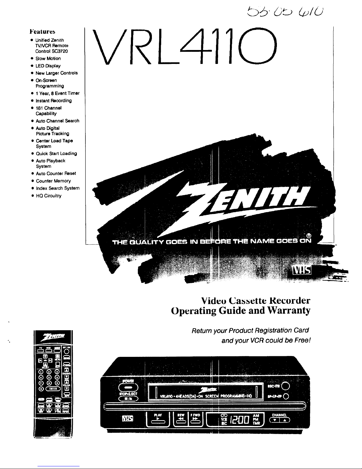
Features
• Unified Zenith
TVNCR Remote
Control SC3720
• Slow Motion
• LED Display
• New Larger Controls
• On-Screen
Programming
• 1 Year, 8 Event Timer
• Instant Recording
• 181 Channel
Capability
• Auto Channel Search
• Auto Digital
Picture Tracking
• Center Load Tape
System
• Quick Start Loading
• Auto Playback
System
• Auto Counter Reset
• Counter Memory
• Index Search System
• HQ Circuitry
VRi 4110
Video Cassette Recorder
Operating Guide and Warranty
Return your Product Registration Card
and your VCR could be Free!
.......... I IIIP'
Page 2
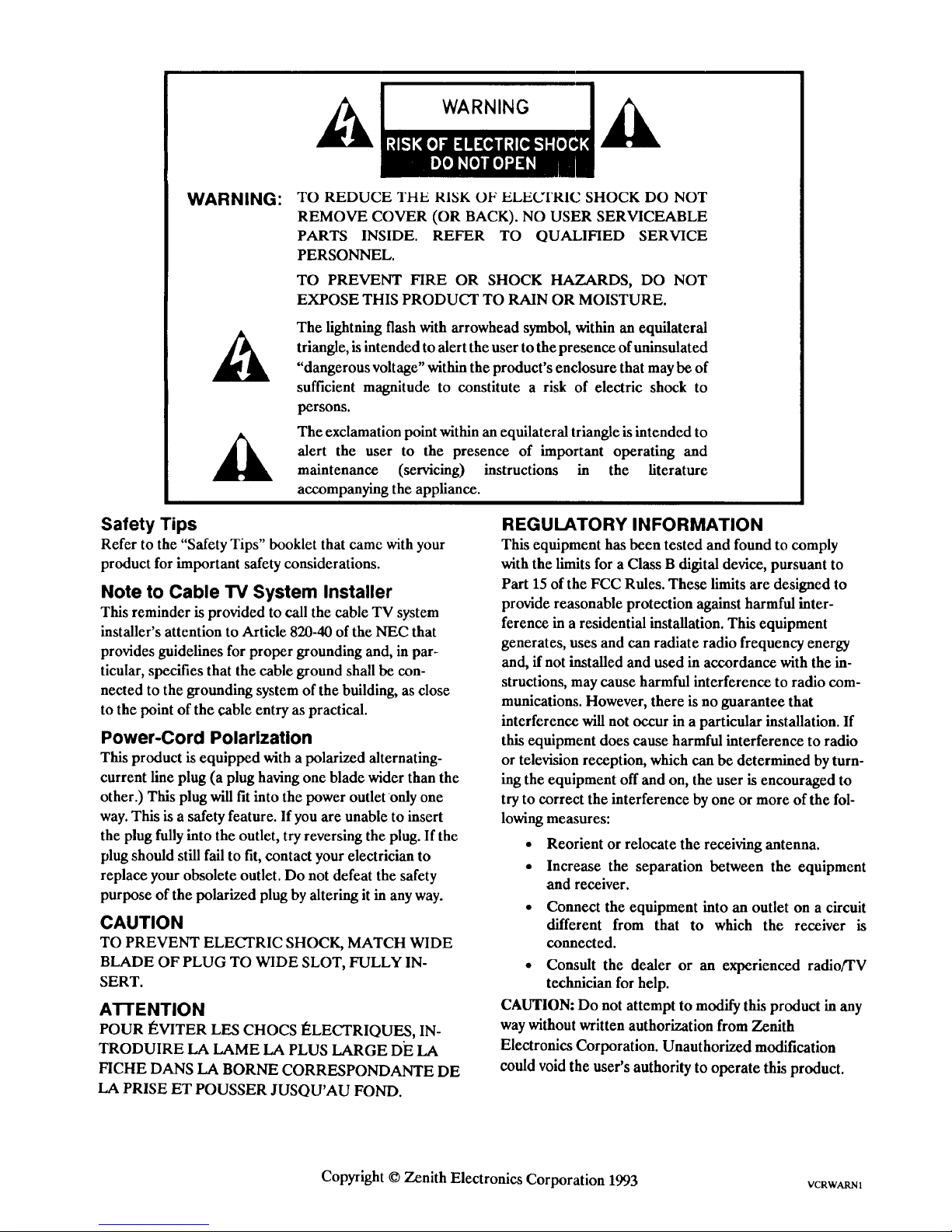
WARNING:
TO REDUCE THE RISK OF ELECq'RIC SHOCK DO NOT
REMOVE COVER (OR BACK). NO USER SERVICEABLE
PARTS INSIDE. REFER TO QUALIFIED SERVICE
PERSONNEL.
TO PREVENT FIRE OR SHOCK HAZARDS, DO NOT
EXPOSE THIS PRODUCT TO RAIN OR MOISTURE.
The lightning flash with arrowhead symbol, within an equilateral
triangle, is intended to alert the user to the presence of uninsulated
"dangerous voltage" within the product's enclosure that may be of
sufficient magnitude to constitute a risk of electric shock to
persons.
The exclamation point within an equilateral triangle is intended to
alert the user to the presence of important operating and
maintenance (servicing) instructions in the literature
accompanying the appliance.
Safety Tips
Refer to the "Safety Tips" booklet that came with your
product for important safety considerations.
Note to Cable TV System Installer
This reminder is provided to call the cable TV system
installer's attention to Article 820-40 of the NEC that
provides guidelines for proper grounding and, in par-
ticular, specifies that the cable ground shall be con-
nected to the grounding system of the building, as close
to the point of the cable entry as practical.
Power-Cord Polarization
This product is equipped with a polarized alternating-
current line plug (a plug having one blade wider than the
other.) This plug will fit into the power outlet only one
way. This is a safety feature. If you are unable to insert
the plug fully into the outlet, try reversing the plug. If the
plug should still fail to fit, contact your electrician to
replace your obsolete outlet. Do not defeat the safety
purpose of the polarized plug by altering it in any way.
CAUTION
TO PREVENT ELECTRIC SHOCK, MATCH WIDE
BLADE OF PLUG TO WIDE SLOT, FULLY IN-
SERT.
ATTENTION
POUR I_VITER LES CHOCS I_LECTRIQUES, IN-
TRODUIRE LA LAME LA PLUS LARGE DE LA
FICHE DANS LA BORNE CORRESPONDANTE DE
LA PRISE ET POUSSER JUSQU'AU FOND.
REGULATORY INFORMATION
This equipment has been tested and found to comply
with the limits for a Class B digital device, pursuant to
Part 15 of the FCC Rules. These limits are designed to
provide reasonable protection against harmful inter-
ference in a residential installation. This equipment
generates, uses and can radiate radio frequency energy
and, if not installed and used in accordance with the in-
structions, may cause harmful interference to radio com-
mtmications. However, there is no guarantee that
interference will not occur in a particular installation. If
this equipment does cause harmful interference to radio
or television reception, which can be determined by turn-
ing the equipment off and on, the user is encouraged to
try to correct the interference by one or more of the fol-
lowing measures:
• Reorient or relocate the receiving antenna.
• Increase the separation between the equipment
and receiver.
• Connect the equipment into an outlet on a circuit
different from that to which the receiver is
connected.
• Consult the dealer or an experienced radio/TV
technician for help.
CAUTION: Do not attempt to modify this product in any
way without written authorization from Zenith
Electronics Corporation. Unauthorized modification
could void the user's authority to operate this product.
Copyright © Zenith Electronics Corporation 1993 VCRWARN1
Page 3
General Information
Introduction
Welcome into the family of Zenith Video Recorder owners.
This guide provides instructions on how to operate your
new VCR. It is supplemented by a booklet containing
Safety Tips. We urge you to read these publications careful-
ly so that you will receive full enjoyment from your new
Zenith VCR for many years to come.
Zenith Electronics Corporation
Customer Service Department
1900 N. Austin Avenue
Chicago, Illinois 60639-5079
Telephone: (312) 745-5152
Mon-Fri, 8:00 a.m. - 4:30 p.m. Central Time
Your new Zenith VCR has been designed and built to give
you the very best in quality, features and performance. There
are approximately 75 regional Zenith distributors and
thousands of distr_utor-approved Zenith video recorder ser-
vice centers throughout the U.S. and Canada who can attend
promptly and effectively to ordinaryservice needs.
If you should have an unusual performance or service problem
that cannot be satisfactorily resolved by your distributor-
approved Zenith video recorder service center, contact the
regional Zenith distributor in your area, or write or call:
Send the model number, serial number, and date of pur-
chase or original installation, with a full explanation of the
problem and the service history. We will welcome the op-
portunity to look into your specific question or problem and
to be of assistance in resolving it promptly.
The model and serial numbers of your new VCR are lo-
cated on the VCR cabinet. For your future convenience and
protection, we suggest that you record these numbers here:
Model No.
Installation Considerations
Before you install your VCR...
Ventilation - Proper ventilation keeps your
Serial No.
VCR running cool. Air circulates through per-
forations in the back and bottom of the cabinet.
Do not block these vents or you will shorten the
life of your VCR.
Power Source - Your VCR is designed to
operate on normal household current, 120 volt
60 Hertz AC. Do not attempt to operate it on
DC current.
Power Cord - Your VCR power cord has a
polarized plug as required by Underwriters'
Laboratories. It has one regular blade and one
wide blade and fits only one way into a standard
electrical outlet. If the blades will not enter
either way, your outlet is very old and non-stand-
• Plugging in Your VCR - Be sure to plug your VCR into
an "unswitched" AC power source. The "switched" AC
outlets found on some video equipment will not continue
supplying power to the VCR once the equipment is
turned off. If the power to the VCR is interrupted for an
extended time, you will have to reset the clock in the VCR.
• Keep the video recorder and video cassette away from
strong magnetic fields.
• Use only Zenith approved and recommended acces-
sory units with your Zenith video recorder to avoid
potential hazards.
• Save the shipping carton and packing material. They
will come in handy if you ever have to ship your video
recorder. For maximum protection, re-pack the video
recorder as it was originally shipped from the factory.
ard. A new outlet should be installed by a qualified
electrician.
Safe Operation - Your VCR is manufactured
_lk nd tested with your safety in mind. However,
unusual stress caused by dropping or mishan-
dling, exposure to flood, fire, rain or moisture,
or accidental spilling of liquids into the VCR,
can result in potential electrical shock or fire hazards. If this
happens, have your VCR checked by a service technician
before using it again.
Please read and observe each safety point in the "Safety
Tips" folder when installing and using your VCR.
Moisture condensation is apt to occur under the following
conditions:
• When the video recorder is moved from a cold place to
a warm place.
• Under extremely humid conditions.
In locations where moisture condensation may occur:
• Keep the power cord plugged into an AC outlet and
the POWER switch set to ON. This will help prevent
condensation from occurring.
• When condensation has occurred, it will not evaporate
quickly once the power is switched on. Wait a few
hours for the video recorder to become dry before
using the video recorder.
i VCRINqR4
Page 4
Specifications
These specifications are subject to change
without notice. Weight and dimensions are ap-
proximate.
Power Requirements
Operating Voltage
120 V, 60 Hz
Power Consumption
19W
Environmental Conditions
Operating Temperature
41" F to 95° F (5°C to 35°C)
Relative Humidity 5% to 80%
Storage Temperature
-4°to + 140° (-20°C to + 60°C)
Relative Humidity 5% to 80%
Physical Characteristics
Dimensions (W x H x D)
14.2 x 3.5 x 13.4 Inches (360 x 88 x 340 mm)
Weight
9.7 Ibs (4.4 kg)
Video System
Format
VHS 1/2 inch (12.7 mm) Cassette
Signal
NTSC color/EIA monochrome (525 lines/50 fields)
Input
1.0 Vp-p, 75 ohms unbalanced, negative sync
Output
1.0 Vp-p, 75 ohms unbalanced, negative sync
Signal to Noise ratio
_>43dB (SP speed)
Signal Processing
HQ enhancement circuitry
Audio Systems
Monaural
1 Channel standard VHS
Frequency Response
70 to 10,000 Hz
Signal to Noise Ratio
_>40dB (SP speed)
Input
Output
Minus 8 dB into
Minus 8 dB into
_>47,000 ohms
< 1,000 ohms
Recording System
Type
Rotary Helical Scan
Heads
4 Heads, Double Azimuth (Slant Design)
Speeds
SP- 1 5/16 IPS (33.34 mm/sec)
LP- 21/32 IPS (16.67 mm/sec)
EP- 7/16 IPS (11.12 mm/sec
Maximum Time
SP- 2 Hours 40 Minutes ('r-160 tapes)
LP- 5 hours 20 minutes (T-160 tapes)
EP- 8 hours (%160 tapes)
Tuning System
Type
50 --800 MHz Frequency Synthesized
VHF Channels
2to 13
UHF Channels
14 to69
CATV Channels
1 to 125 (4A, A to W, W + 1 to W + 84, A-5 to A-1)
Input
1.0 Vp-p, 75 ohms unbalanced
Output
1o0Vp-p, 75 ohms unbalanced
Audio Signals
Monaural (Frequency Modualted)
Timer
Program Capacity
1 Year/8 Events
Power Backup
30 seconds
2_09-0 ii
Page 5
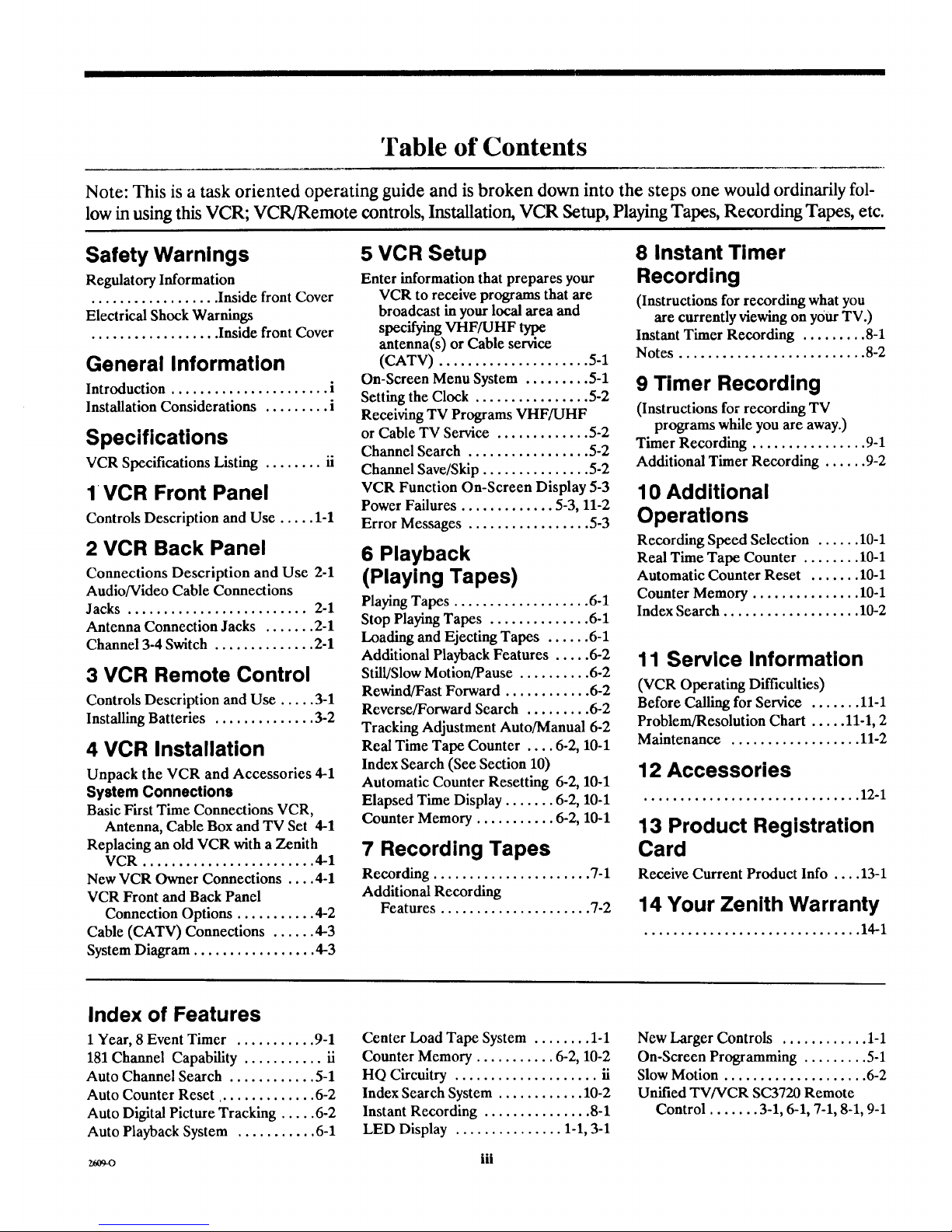
'Fable of Contents
Note: This is a task oriented operating guide and is broken down into the steps one would ordinarily fol-
low in using this VCR; VCR/Remote controls, Installation, VCR Setup, Playing Tapes, Recording Tapes, etc.
Safety Warnings
Regulatory Information
.................. Inside front Cover
Electrical Shock Warnings
.................. Inside front Cover
General Information
Introduction ...................... i
Installation Considerations ......... i
Specifications
VCR Specifications Listing ........ ii
1 VCR Front Panel
Controls Description and Use ..... 1-1
2 VCR Back Panel
Connections Description and Use 2-1
Audio/Video Cable Connections
Jacks ......................... 2-1
Antenna Connection Jacks ....... 2-1
Channel 3-4 Switch .............. 2-1
3 VCR Remote Control
Controls Description and Use ..... 3-1
Installing Batteries .............. 3-2
4 VCR Installation
Unpack the VCR and Accessories 4-1
System Connections
Basic First Time Connections VCR,
Antenna, Cable Box and TV Set 4-1
Replacing an old VCR with a Zenith
VCR ........................ 4-1
New VCR Owner Connections .... 4-1
VCR Front and Back Panel
Connection Options ........... 4-2
Cable (CATV) Connections ...... 4-3
System Diagram ................. 4-3
5 VCR Setup
Enter information that prepares your
VCR to receive programs that are
broadcast inyour local area and
specifying VHF/UHF type
antenna(s) or Cable service
(CATV) ..................... 5-1
On-Screen Menu System ......... 5-1
Setting the Clock ................ 5-2
Receiving TV Programs VHF/UHF
or Cable TV Service ............. 5-2
Channel Search ................. 5-2
Channel Save/Skip ............... 5-2
VCR Function On-Screen Display 5-3
Power Failures ............. 5-3, 11-2
Error Messages ................. 5-3
6 Playback
(Playing Tapes)
Playing Tapes ................... 6-1
Stop Playing Tapes .............. 6-1
Loading and Ejecting Tapes ...... 6-1
Additional Playback Features ..... 6-2
Still/Slow Motion/Pause .......... 6-2
Rewind/Fast Forward ............ 6-2
Reverse/Forward Search ......... 6-2
Tracking Adjustment Auto/Manual 6-2
Real Time Tape Counter .... 6-2, 10-1
Index Search (See Section 10)
Automatic Counter Resetting 6-2, 10-1
Elapsed Time Display ....... 6-2, 10-1
Counter Memory ........... 6-2, 10-1
7 Recording Tapes
Recording ...................... %1
Additional Recording
Features ..................... 7-2
8 Instant Timer
Recording
(Instructions for recording what you
are currently viewing on your TV.)
Instant Timer Recording ......... 8-1
Notes .......................... 8-2
9 Timer Recording
(Instructions for recording TV
programs while you are away.)
Timer Recording ................ 9-1
Additional Timer Recording ...... 9-2
10 Additional
Operations
Recording Speed Selection ...... 10-1
Real Time Tape Counter ........ 10-1
Automatic Counter Reset ....... 10-1
Counter Memory ............... 10-1
Index Search ................... 10-2
11 Service Information
(VCR Operating Difficulties)
Before Calling for Service ....... 11-1
Problem/Resolution Chart ..... 11-1, 2
Maintenance .................. 11-2
12 Accessories
.............................. 12-1
13 Product Registration
Card
Receive Current Product Info .... 13-1
14 Your Zenith Warranty
.............................. 14-1
Index of Features
1Year, 8 Event Timer ........... 9-1
181 Channel Capability ........... ii
Auto Channel Search ............ 5-1
Auto Counter Reset .............. 6-2
Auto Digital Picture Tracking ..... 6-2
Auto Playback System ........... 6-1
Center Load Tape System ........ 1-1
Counter Memory ........... 6-2, 10-2
HQ Circuitry .................... ii
Index Search System ............ 10-2
Instant Recording ............... 8-1
LED Display ............... 1-1, 3-1
New Larger Controls ............ 1-1
On-Screen Programming ......... 5-1
Slow Motion .................... 6-2
Unified TV/VCR SC3720 Remote
Control ....... 3-1, 6-1, 7-1, 8-1, 9-1
iii
Page 6
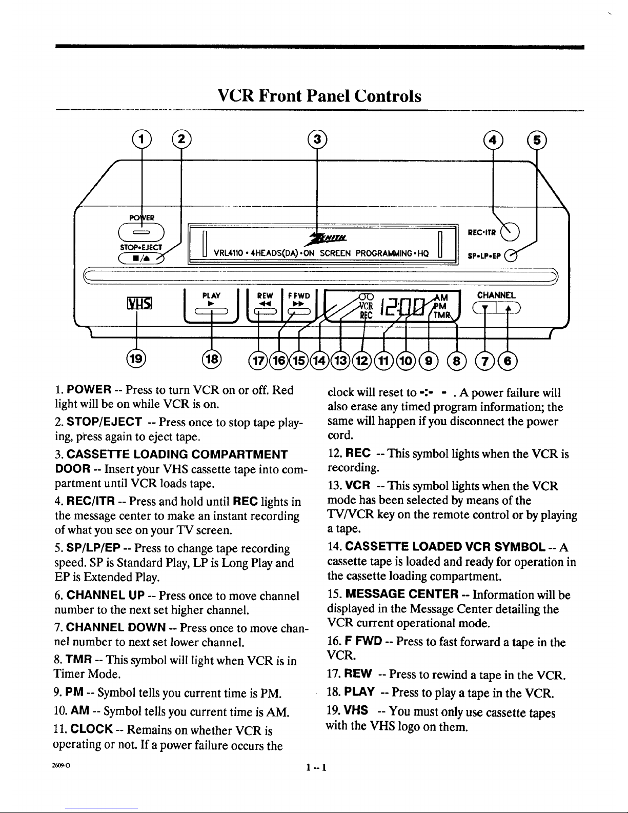
VCR Front Panel Controls
VRL4110 • 4HEADS(DA).ON SCREEN PROGRAMMINGoHQ SP-LP.EP
I ,,- Jl CHANNEL
• I . // V,_R ;HI IL_"_M
(r" i ( / f-
1. POWER -- Press to turn VCR on or off. Red
light will be on while VCR is on.
2. STOP/EJECT -- Press once to stop tape play-
ing, p_'ess again to eject tape.
3. CASSETTE LOADING COMPARTMENT
DOOR -- Insert your VHS cassette tape into com-
partment until VCR loads tape.
4. REC/ITR -- Press and hold until REC lights in
the message center to make an instant recording
of what you see on your TV screen.
5. SP/LP/EP -- Press to change tape recording
speed. SP is Standard Play, LP is Long Play and
EP is Extended Play.
6. CHANNEL UP -- Press once to move channel
number to the next set higher channel.
7. CHANNEL DOWN -- Press once to move chan-
nel number to next set lower channel.
8. TMR -- This symbol will light when VCR is in
Timer Mode.
9. PM -- Symbol tells you current time is PM.
10. AM -- Symbol tells you current time is AM.
11. CLOCK -- Remains on whether VCR is
operating or not. If a power failure occurs the
26O9-0
clock will reset to -:- - . A power failure will
also erase any timed program information; the
same will happen if you disconnect the power
cord.
12. REC -- This symbol lights when the VCR is
recording.
13. VCR -- This symbol lights when the VCR
mode has been selected by means of the
TV/VCR key on the remote control or by playing
a tape.
14 CASSETTE LOADED VCR SYMBOL A
cassette tape is loaded and ready for operation in
the cassette loading compartment.
15. MESSAGE CENTER -- Information will be
displayed in the Message Center detailing the
VCR current operational mode.
16. F FWD -- Press to fast forward a tape in the
VCR.
17. REW -- Press to rewind a tape in the VCR.
18. PLAY -- Press to play a tape in the VCR.
19. VHS -- You must only use cassette tapes
with the VHS logo on them.
1"-1
Page 7
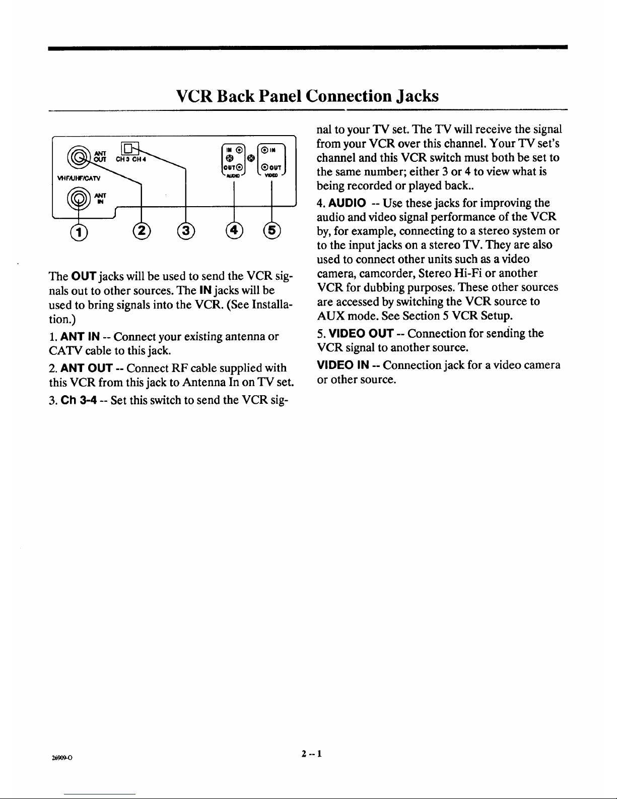
VCR Back Panel Connection Jacks
VHFAJHF/GA_/
The OUT jacks will be used to send the VCR sig-
nals out to other sources. The IN jacks will be
used to bring signals into the VCR. (See Installa-
tion.)
1. ANT IN -- Connect your existing antenna or
CATV cable to this jack.
2. ANT OUT -- Connect RF cable supplied with
this VCR from this jack to Antenna In on TV set.
3. Ch 3-4 -- Set this switch to send the VCR sig-
nal to your TV set. The TV will receive the signal
from your VCR over this channel. Your TV set's
channel and this VCR switch must both be set to
the same number; either 3 or 4 to view what is
being recorded or played back..
4. AUDIO -- Use these jacks for improving the
audio and video signal performance of the VCR
by, for example, connecting to a stereo system or
to the input jacks on a stereo TV. They are also
used to connect other units such as a video
camera, camcorder, Stereo Hi-Fi or another
VCR for dubbing purposes. These other sources
are accessed by switching the VCR source to
AUX mode. See Section 5 VCR Setup.
5. VIDEO OUT -- Connection for sending the
VCR signal to another source.
VIDEO IN -- Connection jack for a video camera
or other source.
2_09-o 2--1
Page 8
Remote Control
Control Keys on the Zenith SC3720 Dual Function Remote Control
and VCR with the remote control will allow you
to operate each unit individually. Some of the ad-
vanced features on your TV cannot be accessed
with the SC3720. Use the remote control
provided with your TV for these advanced fea-
tures.
1.TV - Will light momentarily when mode is
switched to operate TV or when you press a key
on the remote while in the TV Mode.
2. VCR -- Will light momentarily when mode is
switched to operate VCR or when you press a key
on the remote while in the VCR Mode.
3. MODE -- Press to switch control between TV
and VCR.
4. OFF/ON -- Turns VCR or TV off or on when
in that particular mode.
5. MENU -- Press (while in VCR mode) to place
Main Menu (VCR Features) on TV screen.
6. SOURCE -- A function key for your TV, refer
to TV operating guide.
7. FLASHBK -- A function key for your TV, refer
to TV operating guide.
8. QUIT -- Press to exit main menus.
9. CHANNEL -- Press Up arrow to go to next
higher channel, press Down arrow to go to next
lower channel.
10. VOLUME -- For Zenith TVs press Up arrow
to increase volume level, press Down arrow to
decrease volume.
Your Zenith SC3720 remote control operates
your VCR by means of an Infra-Red (IR) Signal.
It must be aimed at the VCR to function and
when controlling the VCR, the VCR light will
come on each time a key is pressed.
Operate Zenith TVs with the SC3720 Remote
This remote can also operate your Zenith Infra-
Red (IR) controlled TV. Switching between TV
26O9-0
11. MUTE -- For Zenith TVs press to turn the
sound coming from your TV off, press again to re-
store the sound.
12. SEARCH -- Use to advance or rewind a
recorded tape to an indexed position.
13. PAUSE -- Press to momentarily cease VCR
record functions or to obtain a still picture while
playing a tape.
3°=1
Page 9

Remote Control
14. TVNCR -- A change key. Press to change be-
tween TV and VCR tuners to show broadcast
programs on the TV screen.
15. F FWD -- Press to advance tape.
16. STOP -- Press to stop playing or recording a
tape.
17. PlAY -- Press to begin playing a tape.
18. REWIND -- Press to rewind tape.
19. RECORD -- Press and hold down until REC
lights in VCR message center to start recording
on a tape.
20. MEMORY -- Use with the tape counter to ac-
cess locations on recorded tapes.
21. AM/PM -- Use to enter AM or PM where re-
quired.
22. TIMER -- Press when all program recording
information has been entered. This will turn off
the VCR until the program time arrives. Press
again to release VCR from Timer Mode.
Note: Once the VCR is in the Timer Mode the
TIMER key must be pressed to release the VCR
from Timer Mode.
23. ENTER -- Press to set entered information.
24. Numbers 0 through 9-- Use these keys to
choose information where applicable. These keys
are also used for direct channel access.
25. SELECT -- Use this key to choose informa-
tion in the menus and sub-menus, where re-
quired.
26. ADJ -- Press to choose information where ap-
plicable; also used to manually adjust the tracking.
Remote Control Battery Compartment
1. &
1. Open battery compartment on the back of the
remote control by using your fingernail to
squeeze the tab lock open.
2. Lift compartment door out and install batteries.
Install two (2) high quality new alkaline AAA
size batteries in the VCR remote control.
Note the positive and negative positions for plac-
ing the batteries in the remote control. Once
fresh batteries are installed into the remote con-
trol it is ready for use.
3. Replace compartment door on remote control.
Notes:
• Be careful not to place heavy objects on top of
the remote control buttons. Prolonged acciden-
tal operation of the remote control will shorten
battery life.
• If you do not use the remote control for a month
or more, remove the batteries. Battery leakage
can cause damage to the remote control.
• Zenith is not responsible for damage caused by
such battery leakage.
2_o 3 -- 2
Page 10
Installation
Unpack The VCR
and All Accessories
(VCR, remote control and
hookup cable. If any parts are
missing notify your nearest
Zenith Dealer.)
Disconnect antenna from your
TV or other units. Position
VCR in desired location away
from any interfering wiring.
Turn the VCR around so you
are looking at the back side and
locate the connections panel.
Note: It is important to place
the VCR where you plan on
using it. After setting the Clock
and completing the Channel
Search, if you disconnect the
VCR power cord all
programmed information will
be erased. (This will also occur
if there is a power failure.)
Antenna Connections
Connect the antenna to the
VCR and the VCR to the TV.
If you have CATV (Cable TV)
use the connections detailed on
page 4-3.
Notes:
1. If you are replacing an ex-
isting VCR, disconnect
your old VCR and connect
the new VCR in the same
way.
2. If this is your first VCR in-
stallation refer to Connec-
tions 4-2 for hookup
procedures.
3. For basic first-time con-
nections, proceed as shown
in Diagram A.
26O9-0
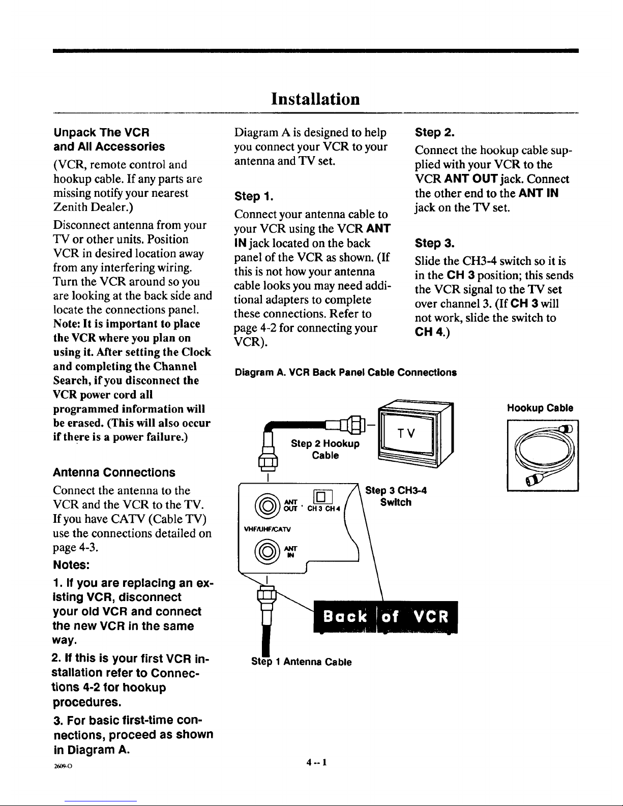
Diagram A is designed to help
you connect your VCR to your
antenna and TV set.
Step 1.
Connect your antenna cable to
your VCR using the VCR ANT
IN jack located on the back
pane] of the VCR as shown. (If
this is not how your antenna
cable looks you may need addi-
tional adapters to complete
these connections. Refer to
page 4-2 for connecting your
VCR).
Step 2.
Connect the hookup cable sup-
plied with your VCR to the
VCR ANT OUT jack. Connect
the other end to the ANT IN
jack on the TV set.
Step 3.
Slide the CH3-4 switch so it is
in the CH 3 position; this sends
the VCR signal to the TV set
over channel 3. (If CH 3 will
not work, slide the switch to
CH 4.)
Diagram A. VCR Back Panel Cable Connections
Step 2 Hookup
Cable
[_ Step 3 CH3-4
rr Switch
OUT" CH3 CH4
VHFIIJHF_AW
Hookup Cable
p 1 Antenna Cable
4°-1
Page 11
Connections
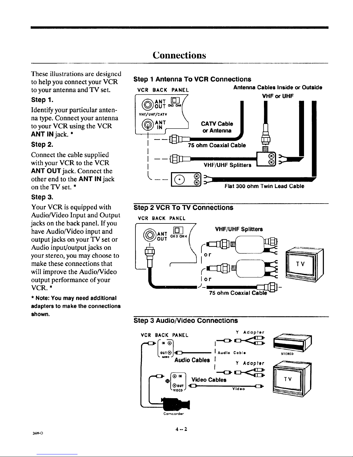
These illustrations are designed
to help you connect your VCR
to your antenna and TV set.
Step 1.
Identify your particular anten-
na type. Connect your antenna
to your VCR using the VCR
ANT IN jack. *
Step 2.
Connect the cable supplied
with your VCR to the VCR
ANT OUT jack. Connect the
other end to the ANT iN jack
on the TV set. *
Step 3.
Your VCR is equipped with
Audio/Video Input and Output
jacks on the back panel. If you
have Audio/Video input and
output jacks on your TV set or
Audio input/output jacks on
your stereo, you may choose to
make these connections that
will improve the Audio/Video
output performance of your
VCR. *
* Note: You may need additional
adapters to make the connections
shown.
Step 1 Antenna To VCR Connections
VCR BACK PANEL Antenna Cables Inside or Outside
( )ANT[] /
OUT c.s c_{
VHF/UHr/CA1V \
f_ANT "_
I
I
I
I ----[:I_:I_
I
[,..._ _
VHF or UHF
CAW Cable
or Antenna
75 ohm Coaxial Cable
VHF/UHF Splitters
Flat 300 ohm Twin Lead Cable
Step 2 VCR To TV Connections
VCR BACK PANEL
lm
OUT CHacH4
t VHF/UHF Splitters
lot
J- able_]-
75 ohm Coaxial C
Step 3 AudioNideo Connections
VCR BACK PANEL
Lo '.?J
Audio Cables
Y Adapter
I Audio Cable
I
Y Adapter
f
Video Cables
Video
SIEREO
Cclrl'lc oFder"
4--2
26O9-O
Page 12

CATV (Cable TV) Converter Box Connections
The connection illustrations
shown in Figures 1 and 2 show
the common methods of con-
necting your VCR to cable ser-
vice and your TV set.
Figure 1.
If your CATV cable connects
directly to your TV (with or
without a converter or
descrambler box) you may use
the connection method shown.
You will not be able to record
an unscrambled (Pay TV) pro-
gram with this connection.
Figure 2.
Using this method you should
be able to record Pay TV
programs with your VCR. You
will only be able to record and
view one channel at-a-time
with this connection.
Notes:
For special cable connections
please refer to your cable
company's service department
or a qualified TV technician.
You may need additional adap-
ters to make the connections
shown.
Figure I CATV "Converter After" VCR Connections
VCR BACK PANEL
ANT [_]
OUT CH3C_4
VHF/UHF/CMV
,);.m
CATV Cable
I+
Converter
Figure 2 Cable TV (Pay TV) To Converter Box To VCR To TV
Set Connections
VCR BACK PANEL
Box
System Diagram
,,Ill,,
"ill"
Antenna
or Cable
I
To
_Camc°rder_:djoO AudiOln__<
ANT
OUT
Optional [
Cable
Box
OUT
VCR
Stereo
I
,.609-0 4 -- 3
Page 13

VCR Menu Settings
On-Screen Menus
This VCR is controlled by an on-screen menu
programming system.
There are 5 VCR Feature menus which you
choose using the remote control. These menus
are then shown on your TV screen. Each menu
and sub-menu asks you to either make a choice
or enter information. Some on-screen menus
have only three screens, like the CLOCK SET
menu, others require more information that has
to be entered or chosen on several screens.
Remote Control MENU Key
(Access to your Menu System)
The MENU key on your remote control is the ac-
cess to the on-screen menu system.
Turn on your TV set.
Turn on the VCR; switch the remote control to
VCR mode. (When you press any key the VCR
LED will light.) Tune the TV to channel 3. Make
sure the switch on the back of the VCR is set to
Ch-3. Note: If you chose Channel 4 to send your
VCR signals to the 'IN set then tune the 'IN to
Channel 4. Whichever decision you made, the
Channel 3-4 Switch on the back of the VCR must
be set and the TV tuned to the same channel.
Press MENU on the remote control; the Main
Menu appears on the TV Screen. These are the
VCR Features. Once the VCR Features are set
up they control the VCR. To choose a feature
press the number key on the remote control that
corresponds to the number of the menu item. For
example, press 1 to bring up the CLOCK SET
menu, press 2 to bring up PROGRAM
RECORD etc.
For the menu system to be accurately functioning
the clock must be set to the correct time.
Note: If you program the VCR with information
and then disconnect the power cord from your
wall socket some of that information will be lost.
If a power failure occurs the result is the same as
if you disconnected the power cord.
2609-O
Main On-Screen Menu (VCR Features)
(Use
2-Press ENTER key
r
-.>
VCR
Press numbe
1 Clock Set
2 Program Record
3 Program
4 Tuning Features
-> 1-Enter program date
Example:03/08
(Use ADJUST to erase)
2-Press ENTER ke_, ,_
ram 1 to record
Month 3/Day 8
Start 1:_ AM/Stop 2.'(15AM
Aux input/Speed SP
__R___.p_____:r9.....
.-> 1-Press SELECT key to
see next program or
Press 'O' key to
erase this program ._
Tuning Features
number key
1-Tuning Band
2-Auto Channel Search
3-Channel Save/Skip
4-Source Select
To quit press QUIT key
VCR Setup
-->Press number key
1-On-Screen Display
To quit press QUIT key
5-°]
Page 14

VCR Menu Settings
Set the Current Time
Set the clock on the front of the VCR in the mes-
sage center. Use the VCR remote control to
show the on-screen display on your TV screen.
1. Press MENU on the remote control. The Main
Menu (VCR Features) appears on your TV
screen.
2. Press I on the remote control.
This will bring you to sub-menu DATE SET.
Set the Month
The first two numbers would be the month. Enter
the month by number; use the numbered keys on
the remote control.
For example April, the 4th month of the year,
would be entered as 04, December the 12th
month of the year would be entered as 12. If you
make an obvious mistake the on-screen display
will show a ? where the correct number should
be. Press ADJ to erase errors.
Programming Tip: If you are having difficulties
press QUIT, then re-enter the Main Menu by
pressing MENU on the remote control to start
over.
Set the Date
The next two numbers would be the date. For ex-
ample 03 would be the 3rd day of November. The
last 2 numbers are the year. For example, 1994
would be entered as 94.
Set the Time
Enter the hours, then the minutes then press
AM/PM on the remote control to choose AM or
PM. For example 9:35 in the morning would be
entered as 09 35 AM.
Receiving VHF/UHF TV Programs or Cable
TV Service
Select Channel 3 on your TV to receive televised
programs from the VCR Tuner.
Press MENU on the remote control to bring up
the Main Menu (VCR Features) on the TV
screen.
Press 4 to choose TUNING FEATURES.
Press 1- Tuning Band. The on-screen menu for
TUNING BAND appears.
Press ADJ to choose TV if you only receive
UHF/VHF CHANNELS. Choose CATV if you
have cable service.
Press SELECT to move to sub-menu AUTO
CHANNEL SEARCH.
VCR Tuner Channel Search
Press ADJ to begin the VCR automatic channel
search program. The VCR searches for the avail-
able channels you receive in your local broadcast
area. When the search program is complete the
channels that were found will be indicated as
CHANNELS FOUND and be followed by the
number of channels that were found. For ex-
ample, CHANNELS FOUND 14.
The VCR has automatically programmed itself to
receive those channels. Press QUIT on the
remote control; the first channel program will ap-
pear on your TV screen.
Note: Make sure you have chosen ON from the
VCR On-Screen Display sub-menu so that the
channel number will appear momentarily in the
upper right hand corner of the TV screen each
time you change channels.
As you press CHANNEL UP or DOWN each
channel the VCR has found will be shown on the
TV screen and the channel number will also be
shown in the VCR message center.
Some Channels may be too weak to send a picture
(adequate viewing signal) to the VCR.
To eliminate these channels in the channel
memory sequence that the VCR has tuned, write
down the numbers of these "weak" channels and
proceed as follows.
Channel Save/Skip
1. Press MENU on the remote control.
2. Choose main menu item 4-TUNING FEA-
TURES.
2609-o 5 -- 2
Page 15

VCR Menu Settings
3. Choose CHANNEL SAVE/SKIP. Each chan-
nel the VCR has found will come up in numerical
sequence. As you press CHANNEL up choose
SKIPPED to delete any weaker channels as
desired. Choose SAVED to keep the channels
with an adequate signal. Repeat this procedure to
eliminate any other weak channels. For example,
if Channel 27 comes in but is too weak for view-
ing, press ADJ so the word SKIPPED appears
next to the weak channel's number.
Press QUIT on the remote control when finished
with the Channel SAVE/SKIP procedure. Now
when you press the CHANNEL UP/DOWN keys
only strong signal channels will be tuned in and
weak ones skipped.
Choosing Channels
The remote control must be set to the VCR
mode to choose channels on the VCR. You can
choose a channel by using either the CHANNEL
UP/DOWN buttons on the VCR or the remote
control, or by using the numbered keys on the
remote control to choose the channel number
directly (32 for example) and pressing ENTER to
switch the VCR Tuner to receive that channel.
The channel number will be shown in the upper
right hand corner of the VCR on-screen display
which will appear momentarily on your TV
screen each time you change channels or initiate
a VCR operation.
VCR Function On-Screen Display
The on-screen display shows the channel you
chose using the VCR tuner, and also the function
the VCR is performing, PLAY, RECORD,
STOP, etc., will be displayed on the TV screen
for a short time.
Typical VCR Status On-Screen Display
STOP-- Indicates the VCR is in the Stop Mode.
SP -- Indicates tape speed is set for Standard
Play.
f _N
STOP VCR CH 11
SP
15 Mon
7:17 AM 1:35:45
.,
VCR CH 11 -- Indicates VCR mode is active and
the VCR Tuner is set to Channel 11.
15 Mon -- The date the VCR is set at.
7:17 AM -- The time the VCR is set at.
1:35:45 -- Tape position indicator is at 1 hour, 35
minutes and 45 seconds.
Power Failures
Occasionally a power failure occurs. The result is
that all the information programmed into the
VCR has to be re-entered. If you were away
when this occurred and notice that the clock time
is missing and -:.... appears, then there was an in-
terruption in electrical service to your VCR.
Error Messages
As you use the menu system, if a problem or con-
flict occurs the menu system alerts you with an
error message on the TV screen, like "No Cas-
sette." For example, if you entered all the infor-
mation for a timed recording and pressed the
TIMER key to set the VCR into TIMER Mode
andno tapewasloadedintothetapeloadingcom-
partment, then that error message would appear
on your TV screen.
z6_o 5 -- 3
Page 16

Playback
•
=
3.
=
J
/
Powilr
IrFO_EJI_2T
l J'- U
VRL4110.4HEADS(D_.ON I SCREEN PROGRAMMING.HQ
®
Turn the TV on and tune it to Channel 3.* (If you have
a Zenith TV use the remote control, press 3, then
ENTER.)
Switch the remote control to VCR mode.
Insert a VHS cassette tape into the VCR loading com-
partment; this turns on the power and the tape will
automatically begin playing if the cassette safety tab has
been removed, or press PLAY on the VCR or the
remote control to start playing the tape.
To stop playing the tape press STOP/EJECT on the
VCR or STOP on the remote control. Press
STOP/EJECT on the VCR again to eject the tape.
Note: The symbols shown on this illustration in the
VCR message center will only appear while the VCR is
performing those functions. However, the clock will
remain on while power is supplied to the VCR.
Automatic Reset-The counter resets when you insert a
tape and when a tape is rewound to its beginning.
Display Elapsed Time- Press ENTER on the remote
control; press it again to leave the tape counter display
on the TV screen.
To Remove Counter Display-Press ENTER on the
remote control.
* Or 4, the same channel that you setwith the CH3-4
switch on the back of the VCR to send the VCR signal
tO the TV set.
SELECT OUIT
®®®
®®®
®®®
Q ( )
_-o 6-- 1
Page 17

Jl I I I ][_ .....
Additional Playback Features
/
IN_VEIt
IJ-oo
VRL.4110.4HI[ADS(DA0.ON SCREEN PROGRAMMING.HQ $P.UP.EP O
t AM J CHA 1_4_L
\
f-
A. Still/Slow Motion Video
B=
Press PAUSE while playing a tape for Still Video. For
Slow Motion, press PAUSE again; follow the on-screen
instructions. Press PLAY to resume tape playing.
Tape Rewind/Fast Forward
In the Stop mode, press and release REW or FFWD to
rewind or fast forward the video cassette tape.
Reverse/Forward Search
In the Play mode, press and release REW or FFWD to
search the video tape recording. If you hold down the
REW or FFWD key the VCR will go into Jet Search,
faster tape scanning.
C. Press PLAY to continue watching the tape.
D. Tracking Adjustment Auto/Manual
E.
F=
Your Zenith VCR automatically adjusts for optimum
tracking every time you play a tape. If however, the
tape was recorded on a different VCR, streaks may
appear. While the tape is playing press and hold down
one of the ADd keys to manually adjust the tracking.
Real Time Tape Counter
The real time tape counter shows you the amount of
time that has elapsed from the start of the recording,
or playback, in actual hours, minutes and seconds.
(1:35:28 = 1 hour, 35 minutes and 28 seconds).
Counter Memory-Press MEMORY on the remote con-
trol, follow the on-screen instructions.
Index Search-(See Additional Operations)
Note: Press ENTER two times to leave the tape counter display on
the TV screen in each mode; STOP, RECORD, PLAY etc.
STOP PAUS[
F FWD
OFF ON
O,
0
FLASHBK
CHANN[L
N
N]
VOLUME
N
CZD
CZD
Srt.ARCH
"W/_R
z_9-o 6 -- 2
Page 18

Recording
/
P_OWll
MO_ENC[
PROGRAMMING. HQ U
120D
tiC 1MR
1. Turn the TV on and tune it to Channel 3.* (If you have
a Zenith TV use the remote control, press 3, then
ENTER.) *See Footnote at the bottom of page 6-1.
2. Change the remote control to VCR Mode.
3. Insert a VHS tape into the VCR tape loading compart-
ment; this turns on the power automatically. Make
sure the cassette safety tab is intact.
4. Tune the VCR to the channel you wish to record. Note:
For recording CATV (cable) broadcasts the cable box
must be on and tuned to the channel you wish to
record. The recording speed will be SP (Standard
Play); to select a different speed press the SP/LP/EP
button to enter the speed selection sequence. (See
Additional Operations for recording speed chart.)
5. Press and hold REC/ITR on the VCR or RECORD on
the remote control until the REC symbol appears in
the VCR message center.
6. Press PAUSE on the remote control to momentarily
cease recording, the REC symbol will begin flashing,
press PAUSE again to resume recording.
7. To stop recording, press PAUSE on the remote control
then STOP/EJECT on the VCR or STOP on the
remote control. (Pressing STOP/EJECT on the VCR
again will eject the tape.)
8. If desired, press REW on the VCR or remote control
to reset the tape to the beginning of the recording, this
readies the tape for playback.
r------]
MENU SOURCE
SELECT QUIT
®
0
MUTE
-- SEARCH
o
ir IrwD TV/Val!
/
Note: CJble/Convetler Box Users
with• CableBoxBeforetheVCR
To recorda program
1. Tune the Cable/Converter Box to
that Channel.
2. Tune the VCR to the Converter Box
outputchannel (usually3 or4); do
notconfusethischannelselection
with the CH 3-4 switch on the back of
the VCR.
3. Tunethe TVto Channel3.*
*See footnote at the bottom of page
6-1.
26o9-0 7 -- 1
Page 19

Additional Recording Features
/ \
POWEm
IIO_ i,Ig.Ct
IIIC.IIll
_ VRLA11C • 4H£ADS(DA) .0_ SCREEN PROGRAMMING • HQ _ _LI'.
f
A. Recording Length of time.
B=
Press and hold down REC/ITR until REC lights in the
VCR message center. The VCR will continue record-
ing until you press PAUSE or STOP; if you press STOP
the VCR will turn off. If you wish to specify a length of
time to record see item A. Instant Timer Recording
page 8-1.
Recording one TV Program While Watching Another
While recording press TV/VCR on the remote control
to turn off the VCR indicator in the VCR message
center. Then tune the TV to the desired channel. (To
return to VCR tuning press TV/VCR again, the VCR
indicator will light again.)*
C. Edit During Recording
Press PAUSE at any time to stop recording momentari-
ly. The REC symbol in the VCR message center will
begin flashing. Press PAUSE again to resume record-
ing. (Using the Pause mode, while recording, instead
of the Stop mode will eliminate video "noise" between
recorded segments when the tape is played back.)
D. Recording Speed
Repeated presses of the SP/LP/EP button will change
the recording tape speed either before or during the
recording setup process. (See Additional Operations,
for Tape Recording Speed Chart.)
*Cable TV companies that supply subscribers with a converter/descrambler box use a
wide diversity of antenna, VCR, cable/converter box to TV connections. Please refer to
your cable company's service department for their options available for recording/watch-
ing the same program.
TV VCR MODE
r---i r---1 C_
SELECT QUIT
®®®
®®®
®®®
Q ( )
0
R..A,_,a(
CHANNEL
IN
VOLU_E
CD
_ (=D C=D
C:::D _ C:::D
STOP _ SEAI_H
7--2
26O9-O
Page 20

Instant Timer Recording
/
I=OWlI
IIIIO_I.IICT
I ,L*V I I ,=wl.wo I I _ .... AM l ,_AN_L \
A. Instant Timer Recording
Press and hold down REC/ITR one time until the REC
symbol lights to enter the VCR into Record mode.
Each time you press REC/ITR thereafter chooses the
amount of recording time in 30 minute intervals. Each
press extends the recording time 30 minutes. (If you do
not press REC/ITR more than once Record mode will
continue until the end of the tape.)
REC/ITR Button Recording Time
2 Presses 30 Minutes, 3 Presses 1 Hour, 4 Presses 1
Hour 30 Minutes, 5 Presses 2 Hours, 6 Presses 2 Hours
30 Minutes, etc. up to a maximum of 4 hours. The time
you choose will be displayed in the VCR clock area and
will count down until recording time is over.
B. Recording One TV Program While Watching Another
Press TV/VCR on the remote control to turn off the
VCR indicator in the VCR message center. Then tune
the TV to the desired channel.
Press TV/VCR again to return to VCR tuning, the VCR
indicator will light again. (See CATV note page 7-1.)
C. Recording Speed Multiple presses of the SP/LP/EP
button will change the recording tape speed either
before or during the instant recording setup procedure.
(See Additional Operations, for Tape Recording
Speed Chart.)
SELECT QUIT
Q®®
®®®
®®®
Q ( E.,E.)
z_,og-o 8 -- l
Page 21

Notes
z_o 8 -- 2
Page 22

Timer Recording
=
1
3.
=
/ \
POwer
U
C-iT--')
Turn the TV on and tune to Channel 3.* (If you have a
Zenith TV use the remote control, press 3, then
ENTER.) *See Footnote at the bottom of page 6-1.
Change the remote control to VCR mode.
Insert a VHS tape into the VCR tape loading compart-
ment. If this is a new tape it will be cued to start at the
beginning; if this is a previously recorded tape advance
or rewind the tape to the position where you want to
begin recording.
Press MENU on the remote control to bring up the
Main Menu (VCR Features).
Press 2 to bring up Program Record. Follow the on-
screen instructions, and enter the recording informa-
tion for Program 1.
5. Press 3 to bring up Program Review, check for ac-
curacy what you entered for program 1. (See page 9-2.)
Note: The clock must be set to the current time to have
the program recorded at the right time.
6. Enter the information for Program 2; if there is one.
Check Program 2 information for accuracy, etc.
7. When programming is complete press QUIT then
TIMER on the remote control to set the VCR in Timer
mode; the VCR will remain off until recording time.
Note: While the VCR is operating in the Timer mode it
cannot be turned on or off manually, and other fea-
tures available in other modes like, PAUSE and STOP,
will _not be available.
®®
® ( -,- )
04rF OI4
-(3
FI.A_QK
CHANNEL
VOLUME
M/TIE
RECORD STOP PAUSE Sr:.ARCH
REW _ F FWD TV/VCR
_-o 9 -- 1
Page 23

Timer Recording
jJ
j_
Program lit6 record:
Month 3//Day 8
Start/lA)5AM/Stop 2:05AM
Chafinel H/Speed SP
Record: Once __._ _ _ ___.___
see next program or
Press 'O' key to
erase this program
Tuning Band
Channel --will automatically come up if you
specified TV in the Tuning Features menu,
Tuning Band submenu.
CATV -- will automatically come up if you
specified CATV in the Tuning Features
menu, Tuning Band submenu before you
entered the Timer program.
Aux Input -- must be specified to record FM
radio broadcasts or to use a surveillance
camera connected to the VIDEO/AUDIO
input jacks on the back of the VCR.
Recording Speed
SP -- Standard Play is the best for video
reproduction.
LP -- Long Play will extend the recording
time available on the tape.
EP -- Extended Play will triple the recording
time over Standard Play.
Recording SeleeUon
Once -- will record a broadcast one time.
Weekly -- will record a broadcast one time
each week.
Daily -- will record one broadcast, one time
each day, Monday through Friday.
The VCR Timer automatically sorts through
the recording information and sets up the
broadcasts based on starting times.
Note: If recording times overlap the on-
screen menu system alerts you to that fact as
you are programming the VCR for recording.
2609-0 9 -- 2
Page 24

I__ 111lTl...... I
Additional Operations
Recording Speed Selection
Your video recorder can record in three speeds:
Standard Play (SP), Long Play (LP), and Ex-
tended Play (EP). SP provides better picture
quality. EP provides longer recording time.
How much you can record depends upon the
recording speed you select and the video cassette
tape length you use. Video cassettes corhe in vary-
ing lengths as shown in the table below.
All tapes, regardless of brand name, are desig-
nated by the letter "T" and by a two or three digit
number. The letter stands for time and the num-
ber represents the amount of time (as expressed
in minutes) available for recording in SP (Stand-
ard Play). As indicated in the table below, the
total amount of recording time available on any
video cassette is doubled when LP is selected and
tripled when EP is selected.
Cassette Record/Play Times
Cassette
Length
SP
(Standard
Play)
30 Minutes
LP
(Long
Play)
1 HourT-30
T-60 1 Hour 2 Hours
T-120 2 Hours 4 Hours
T-160 2 Hours, 5 Hours,
40 Minutes 20 Minutes
EP
(Extended
Play)
1 Hour,
30 Minutes
3 Hours
6 Hours
8 Hours
Tape Counter Resets Automatically
When a tape isinserted into the VCR the
counter is automatically reset to 0:00:00. Once
the counter is reset, the elapsed time begins from
that new position.
To Display Elapsed Time
Press RECORD or PLAY. As the tape advances,
the tape counter times precisely in hours, minutes
and seconds.
Press ENTER to display the on-screen display,
which includes the real time tape counter.
Press ENTER a second time to display counter
time with no on-screen display.
Press ENTER a third time to eliminate all dis-
plays.
Tape Counter Memory
This feature has two positions; On or Off. This
feature enables you to return to a desired point
on a tape. Any point may be selected as your ref-
erence by doing the following:
1. Press RECORD or PLAY.
2. Allow the tape to reach the desired point.
3. Press MEMORY on the remote control to
display the following information on the
TV screen.
Real Time Tape Counter Display
The real time tape counter shows you the
amount of time which has elapsed from the
point at which the tape was inserted in hours,
minutes and seconds. You can also use the tape
counter along with Index Search (described on
the next page) as a guide for locating different
programs on a tape.
Counter : :
Press "0" key
to zero counter
Ol"
Press MEMORY key
for counter memory
(To remove this display
press the QUIT key)
J
2609-0 10 -- 1
Page 25

II II II i l i rl .
Additional Operations
o
Press "0" to zero the counter at that loca-
tion. Press MEMORY to be able to return
Counter Memory is ON
Press MEMORY key
to turn Memory off
(To remove this display
press the QUIT key)
to that location on the tape. The following
display will appear when counter memory
is on.
5. Press QUIT to remove counter display.
To Return to a Desired Point
1. Press STOP.
2. Press REW. The tape will rewind to the
selected zero memory position.
Index Search
Index Search works like an electronic bookmark.
Each time you start a recording, an index mark is
placed on the control track of the video tape,
where it will not interfere with the audio or
video. During Play mode or Stop mode, you can
access any one of these marks (up to a total of 99)
either in fast forward or reverse.
To Start Index Search:
From the PLAY or STOP mode:
1. Press SEARCH on the remote control. The
following display will appear on the TV
screen:
For Index Search:
Code ....
1-Enter index code
Example: 2/not 02
2-Press F FWD/REW key
(To remove this display
press the QUIT key)
2. Press a numbered key that corresponds to
the number of index marks to be passed on
the way to the Index destination from the
present tape location. (Up to 99 marks can
be detected on an individual tape.)
3. Using the remote control press either F FWD
or REW briefly. If either key is held down
too long, the fast forward or rewind mode
will engage.
The tape advances or rewinds past the
number of index marks entered. Playback
begins automatically from that mark.
To Stop Index Search
Press PLAY or STOP.
NOTE: If the end of the tape is reached during
search, the Index mode is cancelled and the tape
rewinds.
21,o9_o 10 -- 2
Page 26

llmllllll lull I IFI II I I IIII
Service Information
Before Calling for Service
Following are some common problems associated with operating a VCR. Please refer to the following
Problem/Resolution Chart before calling for service.
Problem/Resolution Chart
Operating Problems
Observed Condition Possible Cause
No power to the VCR. Power cord not connected.
VCR cannot be turned on. TMR indicator is on in VCR message
center; VCR is in Timer Mode.
Remote control does not function. Batteries are weak.
TV not set to channel 3.
No picture appears on TV screen from
a channel selected using the VCR
Tuner. VCR symbol is lighted in
message center.
Probable Solution
Connect power cord.
Press TIMER to release VCR from
Timer Mode.
Replace with new batteries.
Set TV to channel 3. (Be sure CH3-4
switch on back of VCR is set at CH-3.)
Clock reads -:'- -- There has been a power failure. VCR will have to be reprogrammed. Set
clock to the correct time; redo channel
search if necessary.
Playback Problems
Tape will not rewind or fast forward. Tape is fully rewound or fast forwarded. ]No action required.
Note: This is normal operating sound that will come from the internal mechanical
mechanisms.
VCR operating sound is audible during
operation.
Tape playback picture does not appear
on TV screen.
Video "Noise" appears during normal
playback.
TV not set to channel 3. (Be sure the
VCR symbol is shown in the VCR
message center.)'
Tracking adjusted automatically.
Set TV to Channel 3, make sure the
VCR switch is set to the same channel.
Press "I3/NCFI on the remote control to
switch to VCR mode. VCR symbol will
be shown in message center.
Adjust tracking manually for tapes that
have been recorded on other equipment.
Tape heads are dirty. Clean video heads.
Recording Problems
Observed Condition Possible Cause IProbable Solution
Camcorder image is not shown on TV Source set to TUNER. Set source to Aux.
screen.
Camcorder is not recording. Camcoxder is off. Turn camcorder on.
Tape does not run duringrecording. Rl=Cindicator is flashing;VCR is in Press PAUSEto release VCR from
Pause mode. Pause mode.
TV broadcasts cannot be recorded. Source Select is set to Aux. Set source to Tuner.
Timer recording is not possible. Clock is not set to correct time. Set clock to correct time.
uo+o 11-1
Page 27

n'_1_llllli rlr i ] i L
Service Information
Timer recording is not possible.
Timer has not been programmed
correctly.
[TMR indicator is not on in VCR
lmessage center.
Repro[gram timer. [
Press TIMER to set VCR into Timer
mode.
Some channels are skipped over when
scanning channels.
Tuning Problems
Th9se channels are preset to be skipped. Restore channels to channel search
sequence; select SAVED next to
channel Skipped/Saved.
Channel cannot be switched. VCR set to Timer Mode. Press TIMER to release VCR from
Timer Mode.
Picture and sound are weak or missing. Antenna cable is loose. Tighten connections or replace cable.
Maintenance
Video Head Cleaning
After long periods of use, the video heads may become clogged with accumulated dirt, causing distor-
tion. When this occurs, use do-it-yourself wet head cleaning cassettes available through your Zenith
dealer.
Caution: Do not use dry head cleaning systems. They may seriously damage both the video recorder
and cassette. When visual signs appear (snow, streaking in picture and horizontal pulling of picture) in-
dicating the need for video head cleaning, please see your Zenith approved service center.
Cabinet Cleaning
The outside surfaces of the video recorder may be cleaned with a soft lint-free cloth as required. Use
care not to scratch the VCR message center window during cleaning.
2_o 11 - 2
Page 28

RECOMMENDED ACCESSORIES FOR YOUR VCR
ONLY $29.95
Plus shipping
and handling
MBC4OOP 3 FUNCTION
MULTI-BRAND REMOTE
CONTROL (2 Ibs)
Combining three remotes
into one has never been
easier. Operate your TV, VCR
and cable converter with one
remote control.
• Electronic mode switching
• Easy set-up: simply
depress the "Learn" key
for 5 seconds and enter
the three digit pre-
programmed code
• Operate on-screen menus
and displays
• Ideal replacement for lost
or broken remotes
ALG1310 VHS HEAD
CLEANER (1 Ib)
Keep your VCR or full size
camcorder performing at its
best with Allegro's VHS head
ALG1140 ONE WAY
VIDEO REWINDER
(2 Ib$)
Rewinding tapes in your
VCR or full size camcorder
causes unnecessary wear
on your delicate video
heads. By using our
Allegro VHS tape rewinder,
you can help keep your
equipment in top shape.
ONLY $12.95
Plus shipping
and handling
ALG1141 2 WAY
HIGH-SPEED VIDEO
TAPE REWINDER WITH
FAST FORWARD (2 Ibs)
Allegro's 2 way high
ONLY $9.95
Plus shipping
and handling
cleaner. Monthly maintenance
helps preserve picture quality
and color sharpness.
speed rewinder works
twice as fast as a regular __JC,j
rewinder, and features an f ,,,_
electronic eye that senses /" ,_e;
the end of the tape to _- ,,_v
prevent snapping _" ,t v =t_
Automatic soft eject and _ _O _' o,,_
power shut Off for added _'._'O _ O,_'v .,t_.
convenience. /Q_,_"_ @_Q,4. _'
Order Form Photocopy Page and Detatch Here
To take advantage of this
exciting offer, please fill out Item Number Description
this card and return a photocopy to:
Attn: Accessory Offers
Zenith Video Tech Corporation
1900 N. Austin Avenue
Chicago, Ulinols 80639
Sales Tax: Please add your state sales tax if you
live in one of the following states.
CA 7 3/4%, GA 4%, IL 8 3/4%, KS 4.9%, KY 8%, ME 6%,
PA 8%, RI 7%, TX 7 3/4%, VA 4 t/2%, WA 6 1/2%
Charge card customers, to speed
your order, call toll free 1-800-255-6790
Check payment method you prefer:
[] Check or money order
(made payable to Zenith Video Tech)
[] Visa [] Mastercard
Account Number
111/1111111111/11
Shipping Information
Total (Lbs)
Ship weight
I -51bs
6- 10 Ibs
11 - 15 Ibs
16 - 20 tlos
26 + Ibs
Charge
$4.50
$5.35
$7.0O
$8.75
$10.45
Exp. date
/ /
Mo. Day. Yr.
(Approx.dateofpurchase)
Signature
PLEASE ALLOW 3-4 WEEKS FOR DELIVERY. THANK YOUt
To receive Information on other fine accessory products like those above,
please take a moment to complete the follow4ng:
VCR Model # VCR Sedal #
(from back of unit) (from back of unit)
VCACCESI
Prlce Per Item
Subtotal
State Sales Tax
Ship Charges (See C$1art)
Total Amount of Order
Total Ship
Weight
Ibs
Shipto.
Telephone
Niu'ne
Address
Apt # City
State Zip Code
NOTE: Price and availability subject to change.
Page 29

Product Registration Card
You could win a full refund on your new Zenith product.
Look for the Product Registration Card on your new video
product.
Each month a drawing is held by Zenith from the com-
pleted Product Registration Cards received during the
preceding month. Zenith will reimburse the winner for the
full purchase price of the product purchased.
In order to participate, simply complete and return the
Product Registration Card at once, even if you choose not
to complete the information and interests portion of the
questionnaire.
The odds of winning the free drawing described above
depend on the number of participants. Free drawing
offer is void in Canada and other places where
restricted or prohibited by law. Offer is void for
Hote!/Motel and Institutional models. Rental models
are not eligible.
Product Card lost or misplaced?
The Product Registration Card furnished with your video
product is pre-printed with its Model and Serial numbers.
Please f'dlout the card and mail it at your earliest con-
venience. It is imperative that Zenith know how to reach
you promptly if we discover a safety problem that would af-
fect you. If the original card has been lost or misplaced, you
may use the replacement card provided below. Either card
will qualify you for the free drawing, but you are limited to
only one entry in the drawing. Complete the card, place it in
an envelope and mail it to:
Zenith Electronics Corporation
P. O. Box 173262
Denver, CO 80217-3262
Use the replacement Product Registration Card only if the
original card has been misplaced or lost.
PHOTOCOPY AND CUT ALONG DASHED LINE
Zenith Product Registration Card H5Y01-01
O Please Print Clearly or Type @ Area Code Telephone
,.I-I*. =.D*.. 3.1-1=,.,.I-IN,,= I I IIII I I-I I I
First Name Initial Last Name
IIIIIIIIIIIIIIIIII
Apt. No.
IIIIIIIIIIIIIIIII
II
l
I
llllllllll
Street
I II I I I I I I I
Clty
III I I I I I II
State ZIp Code
I III I I I I I-II I I I
I l l I II
5(_) Date of Purchase
Mo. Day Yr.
IIIIIIIII
"=llrlllllllll
NUMBER
Copy Numbers Here
From Label on Set
Please record the model number
<l==,,m and serial number from the sticker
on the back of your set.
L°... .......... . ........................................................................................... /
VCRCARD3
13 .w1
Page 30

Your Zenith Warranty
Consumer Protection Plan for Zenith Video
Cassette Recorder/Video Player
Welcome into the Zenith family! We believe that you
will be pleased with your new Zenith video product.
Please read this Consumer Protection Plan carefully.
It is a "LIMITED WARRANTY" as defined under
Federal Law. This warranty gives you specific legal
rights, and you may also have other rights that vary
from state to state within the U.S.A.
Zenith's Responsibility
Service Labor -- During a period of 90 days from ef-
fective warranty date, Zenith will pay for service
labor by a U.S. or Canadian distributor-approved
Zenith video recorder service center when needed as
a result of manufacturing defects.
Parts - New or remanufactured replacements for
factory-defective parts will be supplied by a U.S. or
Canadian distr_utor-approved Zenith video recorder/
camcorder service center for one year from effective
warranty date. Such replacement parts are warranted
for the remaining portion of the original warranty
period.
Not Covered - This warranty covers manufacturing
defects and does not cover installation, adjustment of
customer controls in the home, installation or repair
of home antenna systems, cable converters or cable
company-supplied equipment; it also does not cover
damage due to "misuse, abuse, negligence, acts of
God or other causes beyond the control of Zenith.
Any alteration of the product after manufacture
voids this warranty in its entirety.
Owner's Responsibility
Effective Warranty Date - Warranty begins on the
date of original consumer installation. For your con-
venience, keep the dealer's dated bill of sale or
delivery ticket as evidence of the purchase date.
Operating Guide - Read your operating guide care-
fully so that you will understand the operation of
your video product and how to adjust the customer
controls.
Carry-in Service - The video product must be
taken to a U.S. or Canadian distributor-approved
Zenith video recorder service center for warranty ser-
vice and must be picked up by the owner.
"IN Set Performance - It is the owner's respon-
sibility to maintain the TV receiver with which the
video product is used, and the associated antenna sys-
tem, in proper operating condition.
Important: Product Registration - Please flUout
and mail your Product Registration Card. It is im-
perative that Zenith know how to reach you prompt-
ly if we should discover a safety problem that could
affect you.
Warranty Service -- For warranty service informa-
tion, contact your Zenith dealer preferably, or any
U.S. or Canadian distributor-approved Zenith video
recorder service center. Parts and service labor that
are Zenith's responsibility (see above) will be
provided without charge. Other service is at the
owner's expense. If you have any problem in obtain-
ing satisfactory warranty service, write:
Zenith Electronics Corporation
Customer Service Department
1900 N. Austin Avenue
Chicago, Illinois 60639-5079
Telephone: (312) 745-5152
Mon-Fri, 8:00 a.m. - 4:30 p.m. Central Time
NOTE: Before you ask for Warranty service, check the
Operating Guide section entitled, "SERVICE INFOR-
MATION". It may be possible to avoid a service call.
VCRWARR4
14 -- 1
Page 31

VRL 4110 Quick Reference Guide
Quick Play Setup
To play a tape follow this sequence.
1. Turn on the TV and tune it to Channel 3.
2. Make sure the slide switch is set to Channel 3
on the back of the VCR.
3. Turn on the VCR, press POWER on the front
of the VCR or insert a VHS recorded tape into
the VCR tape loading compartment.
4. Press PLAY.
5. When finished watching the tape press
STOP/EJECT twice to eject the tape. Pull the
tape straight out of the VCR.
6_To return to normal TV viewing turn off the
VCR.
Setting The Clock
YCl_ PM
REC TMR
Turn on the TV set and the VCR.
Tune the TV to Channel 3.
Change the remote control to VCR mode.
Press MENU on the remote control to bring up
the Main Menu (VCR Features) on the TV
screen.
Press number 1 to bring up the TIME SET sub-
menu. Follow the on-screen instructions and
enter the information for the current time. Enter
Month, Date, Year etc. (Day of the week, Mon-
day Tuesday etc., comes on automatically). When
finished press QUIT to exit the Time Set Menu.
Recording Tapes
Turn on both the TV set and VCR. (You must
have specified either TV or CATV in the Tuning
Features submenu, see Installation Section.)
Insert a videotape cassette into the cassette load-
ing compartment. (Make sure the safety tab on
the video cassette is intact.)
Select Channel 3 on the TV set. Use the VCR
Tuner to select the channel you wish to record.
When the TV program comes on you wish to
record simply press and hold RECORD on the
remote control or REC/ITR on the VCR until the
REC symbol lights in the VCR message center.
Select the recording speed by pressing SP/LP/EP
repeatedly until the appropriate recording speed
appears in the VCR message center. You can
record a program from 30 minutes up to 4 hours
by pressing REC/ITR to
choose the time. Note: For
recording CATV (cable)
broadcasts the cable box
must be on and tuned to
the same channel you wish
to record.
_o QRG -- 1
Page 32

VRL 4110 Quick Reference Guide
Recording Using the Timer
(Recording while you are away.)
Turn on both the TV set and VCR. (You must
have specified either TV or CATV in the Tuning
Features submenu, see Installation Section.)
Insert a VHS video cassette tape into the cassette
loading compartment on the front of the VCR.
Make sure the safety tab on the video cassette is
intact.
Select Channel 3 on the TV set.
Change the remote control to VCR mode.
Press MENU on the remote control to choose the
Main Menu (VCR FEATURES).
Select 2-PROGRAM RECORD.
Enter the required information using the remote
control. Date of the Program. Start Time and
Stop Time. Choose the Channel. Choose the
Recording Speed. Choose the number of times
you want to record this program, Once, Weekly
(1 time each week) or Daily (the same time each
day Monday through Friday).
When finished programming the Timer, press
TIMER once to turn off the VCR and set it into
TIMER RECORDING mode.
Note: The VCR cannot be turned on while it is in
the TIMER mode. If you want to use the VCR
before your recorded program broadcast time,
press TIMER on the remote control to release
the VCR from the TIMER mode. Once the
TIMER is activated TMR will appear in the VCR
message center.
When the program comes on that you wish to
record you can also watch it, press TV/VCR once
on the remote control then turn on the TV set
and tune it to channel 3.
Note: For recording CATV (cable) broadcasts
the cable box must be on and tuned to the same
channel you wish to record.
When the timed program is finished press
TIMER then the VCR will be released from the
Timer mode.
Recording with a Camcorder
Turn on the TV set and the VCR.
Press MENU on the remote control to choose
the Main Menu (VCR FEATURES).
Choose 4-TUNING FEATURES; press the num-
ber 4 key. This brings up the TUNING FEA-
TURES submenu.
Press number 4 to choose SOURCE SELECT.
Press ADJ to place the arrow next to the word
AUX. Camcorders use the AUX inputs. (When
finished recording you will reset the arrow so it
points to TUNER).
Connect the camcorder cables into the VIDEO
IN, AUDIO IN jacks on the back of the VCR.
Insert a VHS cassette into the VCR cassette
loading compartment. Make sure the safety tab is
intact.
Turn on the camcorder and start recording.
(Refer to camcorder operating guide for informa-
tion about camcorder particulars.) To stop
recording momentarily, press PAUSE on the
remote control. When finished recording press
STOP on the remote control or the VCR. To
eject the tape press STOP/EJECT on the VCR
twice.
When you are finished with the camcorder, the
VCR source select option will have to be
switched back to TUNER.
Press MENU on the remote control.
Press 4 to choose TUNING FEATURES.
Press number 4 to choose SOURCE SELECT.
When that sub-menu comes up on the TV screen
press ADd to place the arrow so it is next to the
word TUNER; this resets the VCR back to nor-
mal VCR mode.
_o_o QRG -- 2
Page 33

Page 34

r - - Ill II II I III I
ZENITH ELE(.._I'RONICS CORPORATION
1000 MILWAUKEE AVENUE
GLENVIEW, ILLINOIS 60025
Printed m Korea
Zenith Part No. 206-2609
Issue O
 Loading...