

Page 1
J
Fe_re$
VR,4235HF
• MTS Hi-Fi Stereo
P_yP_x_rd
p. 11-I
• Bilingual (English-
Spanish)
On-Screen Display
p. 4-3
• Mural-Brand
== :: Remote Conltols _,
p. 3-I
• Slow Motion
StJl_ause
p. 7-2
• Message Center
Display
p. 1-1
• Index Search
p. 11-1
• On-Screen
Programming
p. 4-1
• On-So'sen Display
p. 5-1
• 1 Year, 8 Event Timer
p. 9-1, 10-2
• Instant Reco_'ding
p. 8-1, 11-1
• 18! Channel
Capability
• Auto Channel Search
p. 4-2
• Auto Digital
Picture Tracking
p. 7-2
• Quick Start Loading
p. 7-1
• Auto Head Cleaner
p. 14-3
• Auto Playback
System
p. 7-1
• Auto Counter Reset
p. 7-1
• Counter Memory
p. 7-1
• Auto Daylight
Savings Adjust
p. 13.1
• VCR Rashback
p. 3-7
• HQ Circuitry
Note: Features vary
between models;
some features listed
• may not be available
on your VCR.
VR
4235H
%:
Video Cassette Recorder
Operating Guide and Warranty
11
POWI_R _ =L_JF_ I
,- ®®®,
P
CIA 4-Haad H_F_l_-._pee_ Re*_nd,'Aulo Trsc.W,r_g r
IL.'_U _ ,=
6
Page 2
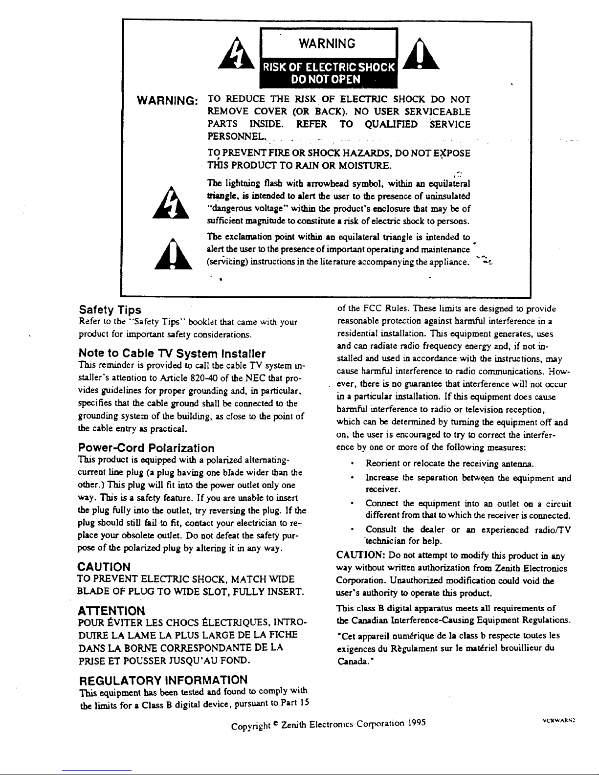
WARNING:
A
TO REDUCE THE RISK OF ELECTRIC SHOCK DO NOT
REMOVE COVER (OR BACK). NO USER SERVICEABLE
PARTS INSIDE. REFER TO QUALIFIED SERVICE
PERSONNEL ..............
TO PREVENT FIRE OR SHOCK HAZARDS, DO NOT E.XPOSE
THIS PRODUCT TO RAIN OR MOISTURE.
0-.
The lightning flash with arrowhead symbol, within an equilateral
I_. gle, is intended to alert the user to the presence of uninsulat6d
"dangerous voltage" within the product's enclosure that may be of
sufficient magnitude to constitute a risk of €lectric shock to persons.
The exclamation point within an equilateral triangle is intended to
alert the user tothe presence of important operating andmaintenance
(scribing) instructions in the literature accompanying the appliance.
q
°
Safety Tips
Refer to the "Safety Tips" booklet that came with your
product for knportant safety considerations.
Note to Cable TV System Installer
This reminder is provided to call the cable TV system in-
staller's attention to Article 820--40 of the NEC that pro-
vides guidelines for proper grounding and, in particular,
specifies that the cable ground shall be connected to the
grounding system of the building, as close to the point of
the cable entry as practical.
Power-Cord Polarization
This product is equipped with a polarized alternating-
current line plug (a plug having one bhde wider than the
other.) This plug will fit into the power outlet only one
way. This is a safety feature. If you are unable to insert
the plug fully into the outlet, try reversing the plug. If the
plug should still fail to fit, contact your electrician to re-.
place your obsolete outlet. Do not defeat the safety pur-
pose of the polarized plug by altering it in any way.
CAUTION
TO PREVENT ELECTRIC SHOCK, MATCH WIDE
BLADE OF PLUG TO WIDE SLOT, FULLY INSERT.
ATTENTION
POUR I_VITER LES CHOCS ]_LECTKIQLTES,INTRO-
DUIRE LA LAME LA PLUS LARGE DE LA FICHE
DANS LA BORNE CORRESPONDANTE DE LA
PRISE ET POUSSER JUSQU'AU FOND.
of the FCC Rules. These limits are designed to provide
reasonable protection against harmful interference in a
residential installation. This equipment generates, uses
and can radiate radio frequency energy and, if not in-
stalled and used in accordance with the instructions, may
cause harmful interference to radio communications. How-
ever, there is no guarantee that interference will not occur
in a particular installation. If this equipment does cause
harmful interference to radio or television reception,
which can be determined by turning the equipment off and
on, the user is encouraged to try to correct the interfer-
ence by one or more of the following measures:
• Reorient or relocate the receiving antenna.
• Increase the separation between the equipment and
receiver.
• Connect the equipment into an outlet on a circuit
different from that to which the receiver is connected.
• Consult the dealer or an experienced radio/TV
technician for help.
CAUTION: Do not attempt to modify this product in any
way without written authorization from Zenith Electronics
Corporation. Unauthorized modification could void the
user's authority to operate this product.
This class B digital apparatus meets all requirements of
the Canadian Interference-Causing Equipment Regulations.
"Cet appareii num_rique de la class b respecte routes les
exigences du R_gulament sur le materiel brouillieur du
Canada."
REGULATORY INFORMATION
This equipment has been tested and found to comply with
the limits for a Class B digital device, pursuant to Part 15
Copyright e Zenith Electronics Corporation 1995 vc=_.'_r_:
Page 3

CONTENTS
Ill General Information
Introduction.
Installation Considerations.
1
1 Installation/Step A
VCR Setup Checklist.
"_: Connectionswithantennaor a cablebox.
Audio/Video and Accessoriesconnections.
FrontAudio/Video InJacks
Ch3-4 Switch.
2 VCR Message Center/Front Controls
VCR Message Center. Overview of VCR buttons.
VCR Accessories.
III
3 Remote Control
Overview of remote keys. Install_ng Batteries; read-
ies remote to operate VCR etc.
Simple instructions for using remote.
4 VCR Features Setup/Step B
Personalize VCR On-screen Menus before playing
or recording tapes.
5 VCR/TV Displays
VCR On-Screen Display.
VCR Message Center Displays.
I
6 Watching 1V
Overview of three tuning options.
Antenna In TV Connections.
Audio/Video In TV Connections.
TV Tuning, VCRTuning,'Cable BoxTuning.
II
7 Playing Tapes
Playing pre-recorded tapes.
Cassette Play/Record Times Chart.
Playing Tapes Options.
|
8 Instant Recording
Recording what you see on your TV screen (VCR
turnedon.)
9 Timer Recording
Recording while you are away (VCR turned off.)
L
10 Instant/Timer Recording
with a Cable. Box
Recording Cable TV (C/_,TV) subscriber program-
....ming that requires a cable/convener box.- • .......
Timer Recording broad._asts with a cable box.
I
11 VCR Plus Recording VR4185
Recording broadcast programming using the VCR
Plus feature with Cable Box control.
I
12 VCR Plus Setup VR4185/Step C
VCR must be set up before yo_ can record VCR
Plus program ming. ""_
Channel Mapping Instructions.
I
13 Additional Information
Index Search.
Real-Time Tape Counter/Memory.
Special Menu.
Auto Clock Set.
Auto Daylight Savings Adjust.
Audio Record Mode.
Audio Playback Mode.
Aux Channel.
(Audio/Video Connections-- use to enhance
audio/video performance from your VCR.)
II
14 Service Information
Operating Difficulties.
Problem Resolution Chart.
Video heads and cabinet cleaning.
15 Specifications
VCR Features Chart.
Your Sears Warranty
Warranty coverage for your VCR.
This product is exclusive to and warranted solely
by Sears. Refer to back cover for specific warranty
information.
Notes: All VCR features, graphics and identifica-
tion labeling are subject to change without prior no-
tice.
Features vary between models----not all features
listed may be available for your particular VCR.
Check VCR Features Chart.
Page 4
GENERAL INFORMATION
Congratulations on buying the _ Video Cassette Recorder (VCR). For you convenience,
please read these simple Instructlons before operatlng your VCR.
NOTES:
_ ._, * ..- This Video Cassette Recorder is compatible with any video cassette bearing the mark _]_. .... - -
• _ is designed to expand yoU opportunities for in-home TV viewing and not for any usage which might violate copy-
right laws.
• ]_1_,, The Video Cassette Recorder (VCR) with this marking incorporates _ high_l_ality picture technology and
is compatible with _ Video Cassette Recorders bearing the _ mark.
Installation Considerations
Before you install your VCR...
Ventilation -- Proper ventilation keeps your
VCR running cool. Air circulates through perfora-
tion.s in the back and bottom of the cabinet. Do
not block these vents or you will shorten the life
of your VCR.
Power Source -- Your VCR is designed to oper-
ate on normal household current, 120 volt 60
Her'z AC. Do not attempt to operate it on DC
current.
Power Cord Q Your VCR power cord has a po-
_k ariz.ed plug as required by Underwriters' Labora-
tories. It has one regular blade and one wide
blade and fits only one way into a standard electri-
cal outlet. If the blades will not enter either way,
your outlet is very old and non-standard. A new outlet should
be installed by a qualified electrician.
Safe Operation -- Your VCR is manufactured
"
and tested with your safety in mind. However,
unusual stress caused by dropping or mishan-
dling, exposure to flood, fire, rain or moisture,
or aceidentai spilling of liquids into the VCR,
can result in potential electrical shock or fire hazards. If this
happens, have your VCR checked by a service technician be-
fore using it again.
Please read and observe each safety point in the "Safety
Tips" folder when installing and using your VCR.
• Plugging in Your VCR -- Be sure to plug your VCR mt_
an "_tched" A_ power source. The "switched" AC
outlets found on some video equipment will not continue
supplying power to the VCR once the equipment is turned
off. If the power to the VCR is interrupted for an extended
time, you will have to reset the clock in the VCR.
• Keep the video recorder and video cassette away from
strong magnetic fields.
• Use only approved and recommended accessory units
with your video recorder to avoid potential hazards.
• Save the shipping carton and packing material. The)"will
come in handy if you ever have to ship your video re-
corder. For maximum protection, re-pack the video re-
corder as it was ori_nally shipped from the factory.
Moisture condensation is apt to occur under the following
conditions:
• When the video recorder is moved from a cold place to a
warm place.
• Under extremely humid conditions.
In locations where moisture condensation may occur:
• Keep the power cord plugged into an AC outlet and the
POWER switch set to ON. This will help prevent con-
densation from occurring.
• When condensation has occurred, it will not evaporate
quickly once the power is switched on. Wait a few hours
for the video recorder to become dry before using the
video recorder.
iii
V]N']T L|
Page 5
INSTALLATION
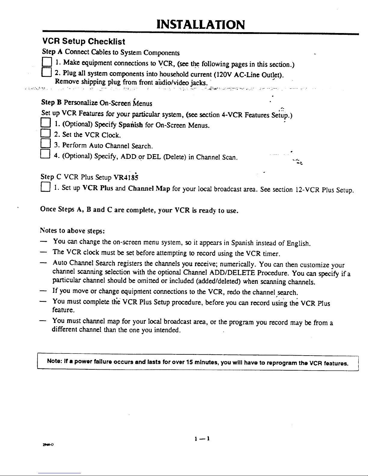
VCR Setup Checklist
Step A Connect Cables to System Components
["7 1. Makeequipment connectionsto VCR, (see _e fol!owingpages in this section.)
['7 2. Plug all system components into householdcurrent(120V AC-Line Outlet).
Remove shipping plug fromfrontahdio/video jacks.
:-:.!'-_"::."- '- " _:" .T'" :::7 _ ,.... _ :-.-,: _-.'" , :.._:-_'_--"'_i7 "':'_" "=--_' _'_ "':_"_' . ..... "_ "
.e
Step B PersonalizeOn-Screen Menus
Set up VCR Features for yourparticular system, (see section 4-VCR Features Setup.)
[--] 1. (Optional) Specify Spafiish for On-Screen Menus.
[--'] 2. Set the VCR Clock.
["7 3. PerformAuto Channel Search.
[-"] 4. (Optional) Specify, ADD or DEL (Delete) in Channel Scan. -
Step C VCR Plus Setup VR4185
F']I. Set up VCR Plus and Channel Map for your local broadcast area. See section 12-VCR Plus Setup.
Once Steps A, B and C are complete, your VCR is ready to use.
Notes to above steps:
You can change the on-screen menu system, so it appears in Spanish instead of English.
The VCR clock must be set before attempting to record using the VCR timer.
Auto Channel Search registers the channels you receive; numerically. You can then customize your
channel scanning selection with the optional Channel ADD/DELETE Procedure. You can specify if a
particular channel should be omitted or included (added/deleted) when scanning channels.
If you move or change equipment connections to the VCR, redo the channel search.
You must complete the VCR Plus Setup procedure, before you can record using the VCR Plus
feature.
You must channel map for your local broadcast area, or the program you record may be from a
different channel than the one you intended.
Note: If • power failure occurs and lasts for over 15 minutes, you will have to reprogram the VCR features. ]
J
Page 6
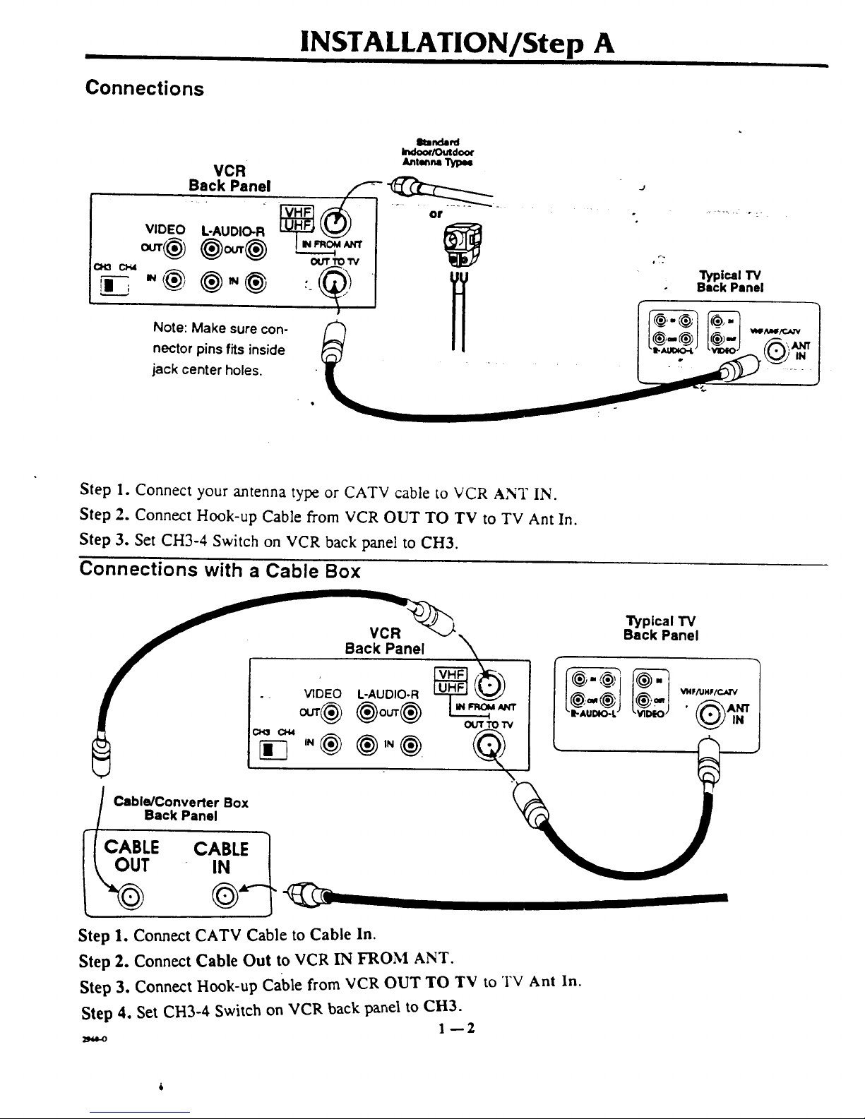
Connections
INSTALLATION/Step A
VCR
Back Panel
VIDEO
"@
L-AUDIO-R
Note: Make sure con-
nector pins fits inside
jack center holes.
elumda_d
Indoo¢/Outdoor
A_nl_n=
ou'r TO I"V
Step 1. Connect your antenna type or CATV cable to VCR ANT IN.
Step 2. Connect Hook-up Cable from VCR OUT TO TV to TV Ant In.
Step 3. Set CH3-4 Switch on VCR back panel to CH3.
Connections with a Cable Box
Back Panel
_ _ ou'r TO 1_
Cable/Converter Box
Back Panel
Step 1. Connect CATV Cable to Cable In.
Step 2. Connect Cable Out to VCR IN FROM ANT.
Step 3. Connect Hook-up Cable from VCR OUT TO TV to TV Ant In.
Step 4. Set CH3-4 Switch on VCR back panel to CH3.
1--2
"i_pical TV
Back Panel
Page 7
INSTALLATION/Step A
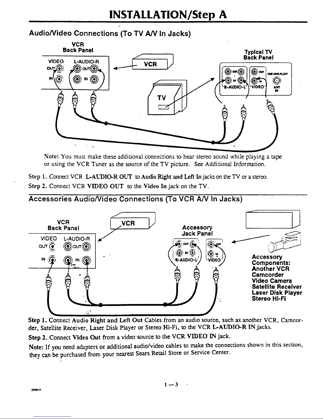
Audio/Video Connections (To TV A/V In Jacks)
VCR
Back Panel
Typical TV
Back Panel
_lf/ul4/c_-v
/u_rr
IN
Note: You must make these additional connections to hear stereo sound while playing a tape
or using the VCR Tuner as the source of the TV picture. See Additional Information.
Step 1. Connect VCR L-AUDIO-R OUT to Audio Right and Left In jacks on the TV or a stereo.
Step 2. Connect VCR VIDEO OUT to the Video In jack on the TV.
Accessories Audio/Video Connections (To VCR A/V In Jacks)
z
VCR _,.
Back Panel ,,,.VCR
VIDEO L-AUDIO-R
IN
Accessory
Jack Panel
I
Accessory
Components:
Another VCR
Camcorder
Video Camera
Satellite Receiver
Laser Disk Player
Stereo Hi-Fi
Step 1. Connect Audio Right and Left Out Cables from an audio source, such as another VCR, Camcor-
der, Satellite Receiver, Laser Disk Player or Stereo Hi-Fi, to the VCR L-AUDIO-R IN jacks.
Step 2. Connect Video Out from a video source to the VCR VIDEO IN jack.
Note: If you need adapters or additional audio/video cables to make the connections shown in this section,
they can be purchased from your nearest Sears Retail Store or Service Center.
1--3
Page 8
INSTALLATION/Step A
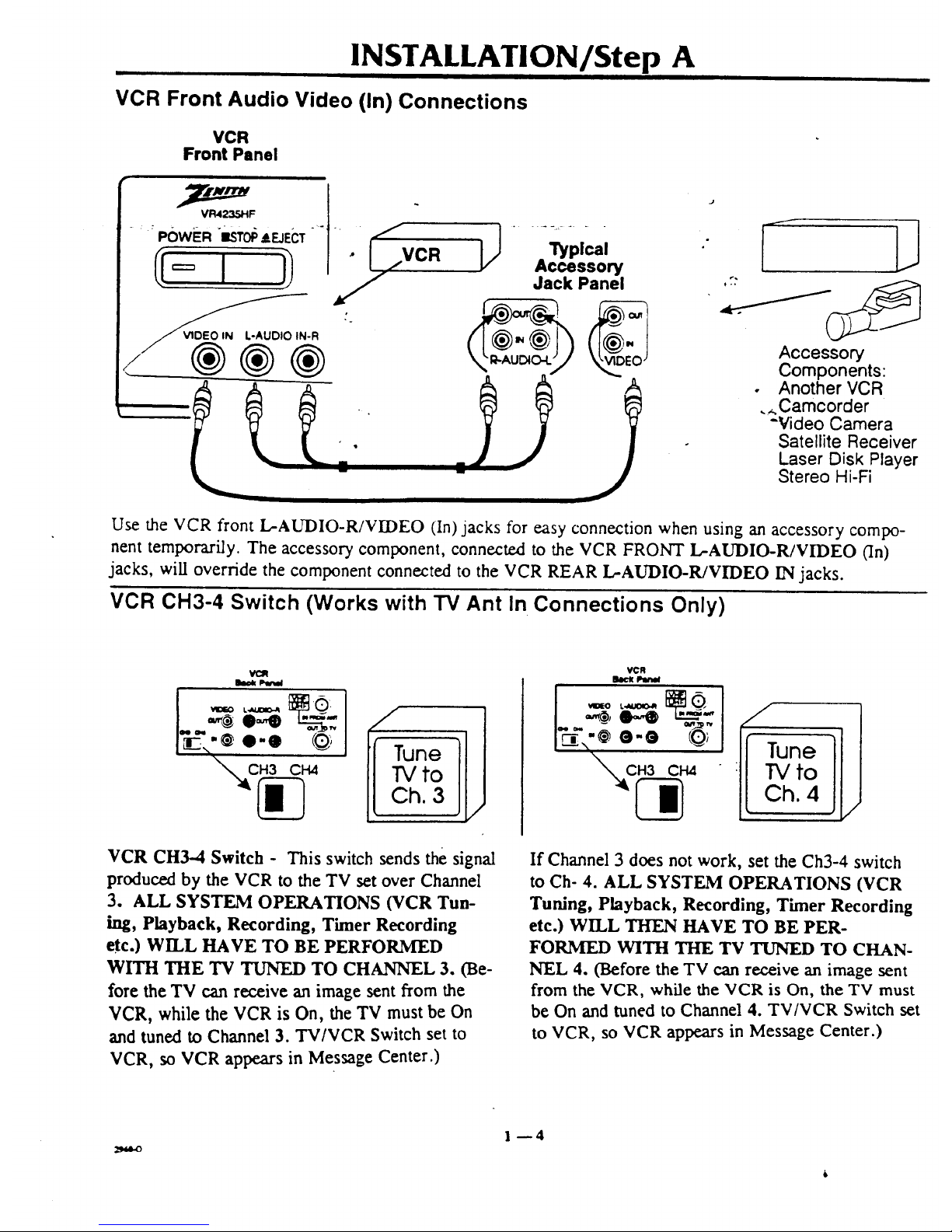
VCR Front Audio Video (In) Connections
VCR
Front Panel
.... POWER _ISTOp&EJECT -" . _,-
_-R
®®®
l_plcel
Accessory
Jack Panel
J
,7: /_
Accessory
Components:
• Another VCR
._.Camcorder
-Video Camera
Satellite Receiver
Laser Disk Player
Stereo Hi-Fi
Use the VCR front L-AUDIO-R/VIDEO (In)jacks for easy connection when using an accessory compo-
nent temporarily. The accessory component, connected to the VCR FRONT L-AUDIO-R/VIDEO (In)
jacks, will override the component connected to the VCR REAR L-AUDIO-R/VIDEO IN jacks.
VCR CH3-4 Switch (Works with TV Ant In Connections Only)
to
h. 3
VCR CH3-4 Switch - This switch sends the signal
produced by the VCR to the TV set over Channel
3. ALL SYSTEM OPERATIONS (VCR Tun-
hag, Playback, Recording, Timer Recording
etc.) WILL HAVE TO BE PERFORMED
WITH THE TV TUNED TO CHANNEL 3. (Be-
fore the TV can receive an image sent from the
VCR, while the VCR is On, the TV must be On
and tuned to Channel 3. TV/VCR Switch set to
VCR, so VCR appears in Message Center.)
VCR
loclt IJw_l
If Channel 3 does not work, set the Ch3-4 switch
to Ch- 4. ALL SYSTEM OPERATIONS (VCR
Tuning, Playback, Recording, Timer Recording
etc.) WILL THEN HAVE TO BE PER-
FORMED WITH THE TV TUNED TO CHAN-
NEL 4. (Before the TV can receive an image sent
from the VCR, while the VCR is On, the TV must
be On and tuned to Channel 4. TV/VCR Switch set
to VCR, so VCR appears in Message Center.)
1--4
Page 9

VCR Front Panel
VCR FRONT PANEL CONTROLS
Cassette Loaded in VCR Symbol
Stop/Eject Key
On/Off
Switch
Cassette Loading
Compartment
Appears When Clock Time is AM/PM
Tape Recording/Playing
Ophons
i
Front Alternate Input
Audio, Video Jacks
VCR Performing
a Function Symbol
J
DA 4-Head Hi-FilHi-Speed Rewind/Auto Tracking i
I:/./-/I'7
i
i}
,ql.41_=_:!,,"PLAY),.I,._
SP?EP • _EC,'tTR
({ ' }j
C_ANNEL
T C:::::::::::D
\ I
Channel Up/Down
Selectors
Message Center Window_"_
(Displays and Symbols Depend Timer Mode
on Particular VCR Function) Indicator
Operate your VCR using the" front panel buttons or
the Remote Cor_.ol keys.
VCR Accessories
Hookup Cable
2--1
Page 10
REMOTE CONTROL MBR3350-02
I II I I I
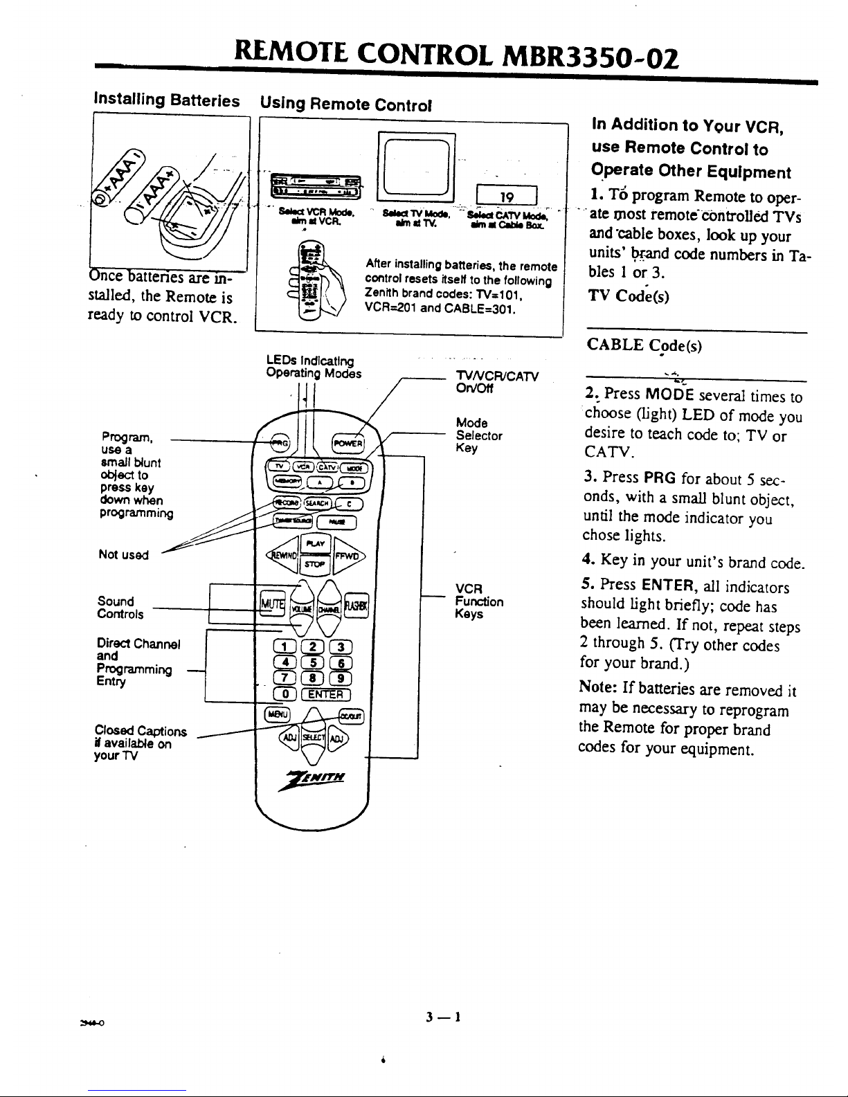
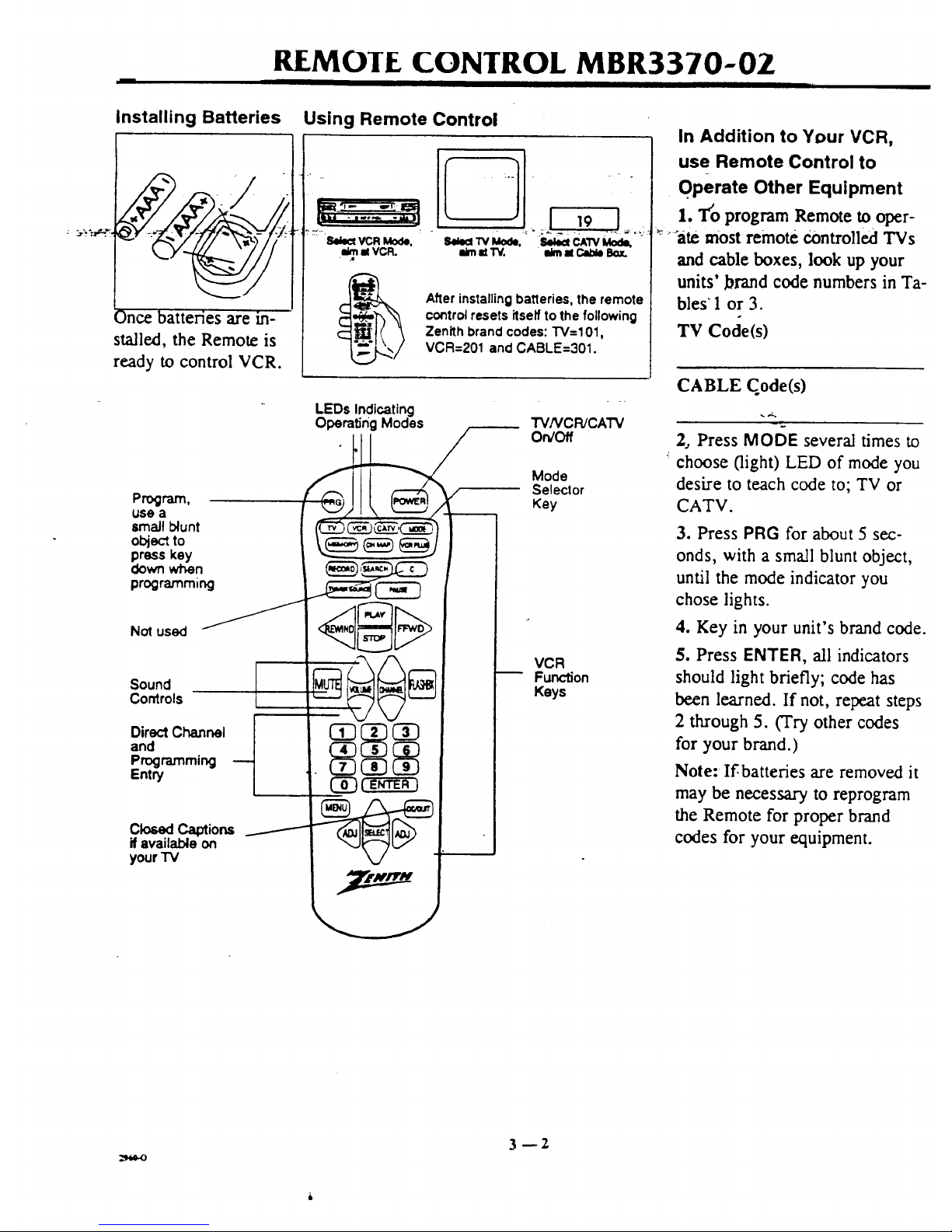
Installing Batteries Using Remote Control
.4
_)nce batteries are in--
stalled, the Remote is
ready to control VCR.
r-
..... 8I_IV'Mo_, -'bI_CAWMo_
i_ =t W. eJmMCab_ Bo_.
After installing batteries, the remote
control resets itself to the following
Zenith brand codes: TV=101,
VCR=201 and CABLE=301.
Program.
use a
small blunt
object to
press key
down when
programming
Not used
Sound
Controls
DirectChannel
and
Programming
Entry
ClosedCaptions
ifavailable on
your "IV
LEDs Indlcatlng
Operating Modes
TVNCR/CATV
On/Off
Mode
Selector
Key
VCR
Function
Keys
In Addition to Your VCR,
use Remote Control to
Qperate Other Equipment
I. T6 program Remote to oper-
ate most remote'€ontroUed TVs
and "cable boxes, look up your
units' _and code numbers in Ta-
bles 1 or 3.
Tv Code(s)
CABLE Code(s)
_¢..
2. Press MODE several times to
:choose (light) LED of mode you
desire to teach code to; TV or
CATV.
3. Press PRG for about 5 sec-
onds, with a small blunt object,
until the mode indicator you
chose lights.
4. Key in your unit's brand code.
5. Press ENTER, all indicators
should light briefly; code has
been learned. If not, repeat steps
2 through 5. (Try other codes
for your brand.)
Note: If batteries are removed it
may be necessary to reprogram
the Remote for proper brand
codes for your equipment.
3fl
Page 11
REMOIE CONTROL MBR3370-OZ
Installing Batteries
¢S ate m-
stalled, the Remote is
ready to control VCR.
Using Remote Control
llelect VCR Mode.
el VCR.
i_midW. ilimal Clide Box.
Afler installing batleries, the remote
control resets itself to the following
Zenith brand codes: "1"V=101,
VCR=201 and CABLE=301.
LEDs Indicating
OperatingModes
Program,
usea _/ I "_."_"_Z
lmaJl blunt (_)_ c_--'C__) I I
obj_:_to _,_ c;-_ _,,_ / I I
press key _--_ "_" "_-'J I I
programm,ng _ _ I
Direct Channel I 03 I
and
your i v M/
TV/VCR/CATV
On/Off
Mode
Selector
Key
VCR
Function
Keys
In Addition to Your VCR,
use Remote Control to
OPerate Other Equipment
1. T'o program Remote to oper-
_ :'-'ate most remote Controlled TVs
and cable boxes, look up your
units' brand code numbers in Ta-
bles 1 or 3.
TV Code(s)
CABLE Code(s)
2, Press MODE several times to
choose (light) LED of mode you
desire to teach code to; TV or
CATV.
3. Press PRG for about 5 sec-
onds, with a small blunt object,
until the mode indicator you
chose lights.
4. Key in your unit's brand code.
5. Press ENTER, all indicators
should light briefly; code has
been learned. If not, repeat steps
2 through 5. (Try other codes
for your brand.)
Note: If,batteries are removed it
may be necessary to reprogram
the Remote for proper brand
codes for your equipment.
3--2
Page 12
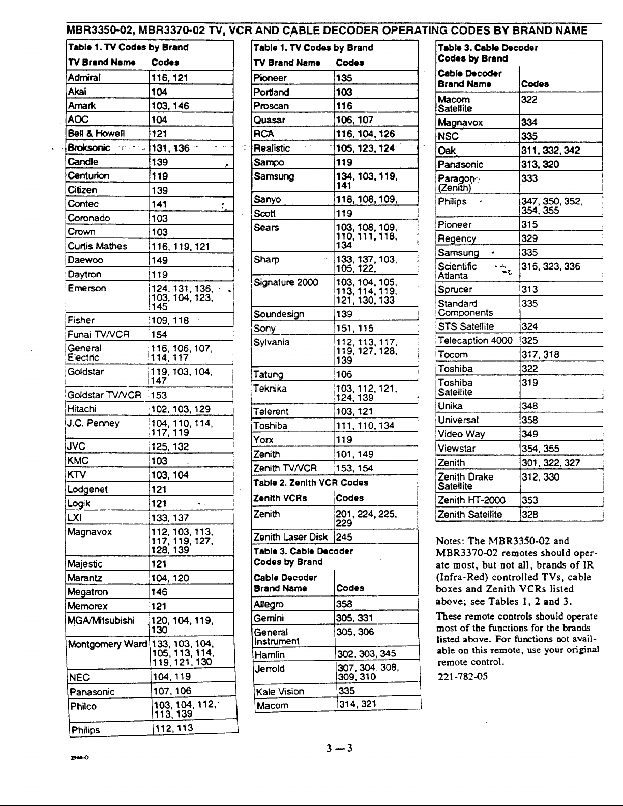
MBR3350-02, MBR3370-02 "FV,VCR AND C,ABLE DECODER OPERATING CODES BY BRAND NAME
Table 1. TV Codes by Brand Table 1. TV Codes by Brand Table 3. Cable Decoder
TV Brand Name Codes
Admiral 116, 121
Akai 104
Amark 103, 146
AOC 104
Bell & Howell 121
Bmksonic _.:._ . 131,136 .......
Candle 139 .,
Centurion 119
Citizen 139
Contec :141 •
"x
Coronado 103
Crown 103
Curtis Mathes 116, 119, 121
I
Daewoo J149
IDaytron il 19
L
iEmerson 124, 131,136, • .
103, 104, 123,
J 145
Fisher 109, 118
iFunai TV/VCR 154
i
General 116, 106, 107,
Electdc 114, 117
iGoldstar i119, 103, 104,
t 1147
IGoldstar "I'V/VCR 1153
Hitachi 1102,103, 129
J.C. Penney !117,119t104'110, 114,
JVC ',125, 132
KMC 1103
I
KTV 103,
LodQenet 121
Locjik 121
L.XI 133,
Magnavox 112,
Majestic
Marantz
Megatron
Memorex
MGNMitsubishi
MontgomeryWard
NEC
Panasonic
iPhilco
Philips
104
137
103, 113,
117, 119, 127,
128, 139
121
104, 120
146
121
120, 104, 119,
130
,133, 103, 104,
105, 113, 114,
119, 121,130
104,119
,107, 106
103, 104,
113, 139
112,113
112,"
I
i
I
TV Brand Name Codes
Pioneer
Por'dand
)roscan
Quasar 107
RCA 104,126
Realistic - 123, 124 : - -
Sampo
Samsung 103, 119,
Sanyo 108, 109,
Scott
Sears 108,109,
111,118,
137, 103,
122,
Sharp
Signature 2000
135
103
116
106,
116,
105,
119
134,
141
118,
119
103,
110,
134
133,
105,
103,
113,
121,
139
1151,
!
!112,
119,
139
t106
103, 112,
124, 139
103, 121
111,110,
119
101,149
153, 154
104,105,
114,119,
130, 133
Soundesign
Sony 115
Sylvania 113, 117,
127, 128,
Tatung
Teknika 121,
Telerent
Toshiba 134
Yorx
Zenith
4
Zenith "rv/vcR
Table 2. Zenith VCR Codes
Zenith VCRs Codes
Zenith 201,224, 225,
229
Zenith Laser Disk 245
Table 3. Cable Decoder
Codes by Brand
Cable Decoder
Brand Name Codes
358
305,331
305,306
302,303,345
307,304,308,
309,310
-Kale Vision 335
_lacom 1314, 321
Allegro
Gemini
General
Instrument
Hamlin
Jerrold
i
J
Codes by Brand
;able Decoder
Irand Name
Macom
Satellite
Mag_vox
NSC
Oak,
Panasonic
)aragon::
Zenith)'
Philips
Codes
322
334
335
3111 332, 342
313, 320
I
347, 350, 352, !
354, 355
Pioneer 315 ;
Regency 329 I
Samsung o 335
Scientific _._. 316, 323,336
AtJanta ":
!
Sprucer !313
Standard !335
Components
iSTS Satellite 324
Telecaption 4000 !325
ITocom 1317,318
'Toshiba
Satell te
Universal
L
Video Way
Viewstar
Zenith
Zenith Drake
Satellite
Zenith HT-2000
Zenith Satellite
349
354, 355
301,322, 327
312, 330
353
328
Notes: The MBR3350-02 and
MBR3370-02 remotes should oper-
ate most, but not all, brands of IR
(Infra-Red) controlled TVs, cable
boxes and Zenith VCRs listed
above; see Tables 1, 2 and 3.
These remote controls should operate
most of the functions for the brands
listed above. For functions not avail-
able on this remote, use your original
remote control.
221-782-05
I
J
i
!
3--3
Page 13

REMOTE CONTROL KEY DESCRIPTIONS
II I I
A - B - C_ Features not used.
ADJ (ADJUST Left/Right)-
Use to modify on-screenmenu
optionsand to adjusttape play-
backtracking.
• "_CC/QUITmUse to exit any oTi-_......
screen menu and to access ,
Closed Captions or Text options
if available on TV.
CH MAP-- Press to begin "
VCR Plus Setup.
CHANNEL (Up/Down)-- Use
to change channels one at-a-time.
" °
E,N'rERm Use for program-
ruing on-screen menus. Press • •
channel number(s) then ENTER
for direct channel entry.
FF, FAST Fa,VD, F F3,VD--
Use to advance tape rapidly.
FLASHBK (Flashback)-- Use
during tape playback to return to
previous VCR channel.
F3VD m Twist shuttle toward
this direction to advance tape
playback one frame at-a-time.
gZEMORY-- Use to zero Real-
Time tapecounter or return tape
to M 0:00:00 position.
Nff_.,NU-- Press to display on-
screen menu options.
MODE-- Mode selector.
MUTF,-- Press to turn off
sound, press again torestore.
Numbered keysm Use to
eh6ose channels and enter pro-
SEARCH-- Use to access re-
cording start locations.
•SELECT (Up/Down)-- Use to
choose on-screenmenu options.
SOIJRCE-- OperatesSource
gramming informati6ii.Press ....:"""function on some TVs.
channel number(s), then ENTER
for direct channel entry.
PAUSE-- Use to pause tape
playbackor record.
PLAY-- Use tobegintapeplay-
back.
POWER--Turns VCR on and
off.Turns VCR Timer On and
Off.
PRG-- Press to begin Remote
control Brand Code program-
ming.
QUIT-- Use to exit any on-
screen menu.
RECORD-- Use to access re-
cord feature.
REV-- Twist shuttle toward
this direction to reverse tape
playback direction one frame at-
a-time.
REW, REWIND-- Use to re-
wind tape rapidly.
REWIND-- Use to rewind tape
rapidly.
SPEEDm Use to change indi-
cated r_eording speed.
STILl.,--.--Press during playback
to freeze tape frame.
STOP-- Use to cancel VCR
functions, like tape playback or
record modes.
TV VCR CATV-- Mode indica-
: tor lights.
TV/VCR-- Use to switch TV
picture from VCR tuner or play-
back to TV tuner.
TV/VCR SOURCE-- Use to
switch TV picture from VCR
tuner or playback to TV tuner.
VCRPLUS_ Press to begin
VCR Plus Recording procedure.
VOLUME-- Useto increase/de-
crease sound level.
VCR CBL TV w Mode selec-
tor keys.
3--6
Page 14

VCR FEATURES SETUP/Step B
I i i
To set up VCR features see following pages.
Perform steps in order as instructed, I, 2, 3, etc.,
to set up each feature.
Overview: VCR Features On-Screen Menus and Submenus
The example below shows how to use Remote Con-
trol to access on-screen menus.
Press MENU to access on-screen menus.
Use up/down/left/right arrows to select and adjust
- VCR options.
t
I
I
CLOCK TIMER SETUP AUDIO
4 II_ to select
"MENU" to adjust
To exit press 'QUIT'
J
Use
Remote Control
Press
MENU
(2D--
'_3LOCK
MENU
('ToSet
VCR Clock)
TIMER
MENU
(3"0"13mer
Record a Program)
SETUP
MENU
(To Personalize
On-Screen Menus)
Use to choose
and modify options
AUDIO
MENU
(To Specify
Sound Play/Record
Options)
4Jl
Page 15

• ii
Features Setup Requirements
TV and VCR on.
TV tuned to Channel 3 or set up with the TV
Audio/Video In Jacks as the source of the TV pic-
ture.
TV/VCR Switch on remote control set ;it VCR.
V(2R FEATURES SETUP/Step B
Features Setup Requirements with a Cable Box.
TV, VCR and Cable Box On.
"IVtuned to Channel 3 or set up with the TV
Audio Video In jacks as the source of the "IVpic-
ture. VCR tuned to Cable Box output channel num-
ber 2, 3, 4, 5 or 6. "
..... •, (VCR symbol appears in VCR Message Center win-_"---TV/VCR Switch on remote control set-at VCR. -
dow.) . (VCR symbol appears in VCR Message Center win-
dow.)
(Optional Language Select) Specifying Spanish for On-Screen Menus
1 2 3 4 5
AUTOCHANNEL
TUNINGBAND
CH./_D/DEL
SOURCESELECT
ON-SCREENDISPLAY
• LANGUAGESELECT
#touma:=l,_=.to_i_
Toe_ pro_'QUIT'
w
Step 1. Turn VCR on.
Step 2. Press MENU. Press ADJUST Left/Right
repeatedly to choose SETUP, press MENU.
Step 3. Press SELECT down arrow repeatedly to
choose LANGUAGE SELECT.
Step 4. Press ADJUST Left/Right to choose
Spanish.
Step 5. Press QUIT when finished.
Specifying Tuning Band .... 'iV or CAW
To Select English Menus
Step 1. Turn VCR on.
Step 2. Press MENU. Press ADJUST Left/Right
repeatedly to choose PRE, press ME,_.
Step 3. Press SELECT down arrow repeatedly to
choose IDIOMA.
Step 4. Press ADJUST Left/Right to choose
I?qGLES.
Step 5. Press QUIT when finished.
1 2 " 3 4
5
AUTOCHANNEL
• TUNINGBAND
CH.ADD/OEL
SOURCESELECT
ON-SCREENDISPLAY
LANGUAGESELECT
Tooxl _ 'QUIT"
Step 1. Turn VCR on.
Step 2. Press MENU. Press ADJUST Left/Right
repeatedly to select SETUP, press MENU.
Step 3. Use SELECT Up/Down arrows to choose
TUNING BAND.
Step 4. Use ADJUST Left/Right arrows to choose
TV, for an antenna, or CATV if you subscribe to
cable service.
Step 5. Press QUIT when finished.
Page 16

VCR FEATURES SETUP/Step B
Using Auto Channel (Search), VCR saves available channels In memory
1 2 3 4 5
Step 1. Turn VCR on.
• AUTOCHANNEL
TUNINGBAND
CH.ADD/DEL
.... 80URCESELECT.....
ON'SCREENDISPLAY
_,LANGUAGESELECT
Toult prom'(_.JIT"
Step 2. Press MENU. Press ADJUST Left/Right
repeatedly to choose SETUP, press MENU.
Step 3. Use SELECT Up/Down arrows to choose
AUTO CHANNEL.
J
0r. " '
Step 4. Press ADJUST to begin search.
Step 5. Press QUIT when search is finished.
(Optional) Using Channel Scan Add or Delete Procedure
1 2 3 4 5
AUTO CHANNEL
TUNINGBAND
Cl-(.ADD/DEL
SOURCE SELECT
ON-SCREENDISPLAY
LANGUAGE SELECT
_to Nk_t ,o. t0 _lju=t
To ex_ _ 'CKJI'T"
Step 1. Turn VCR on.
Step 2. Press MENU. Press ADJUST Left/Right
repeatedly to choose SETUP, press MENIJ.
Step 3. Press SELECT ui)/Down arrows to
choose CH ADD/DEL.
Step 4. Use numbered keys to choose channels and
ADJUST LefiJR.ight to choose ADD or DEL.
Step 5. Press QUIT when finished.
4--3
.-_$,FO
Page 17

VCR FEATURES SETUP/Step B
Setting The VCR Clock
1 2
3 4 5 6
O3
MONTH:JANUARY
DAY :10TIlE
YEAR :1995
" TIME :12:00PM
#t=_ o t0 adlum
're exll ixma 'OUff'
J
r.
t.-
Step 1. Turn VCR on.
Step 2. Press MENU.
Step 3. Press MENU.
Step 4-5. Use SELECT Up/Do_vn arrows and AD-
JUST Left/Right arrows to choose and specify cur-
rent time. For example: Use SELECT Up/Down
arrows to choose MONTH position, use ADJUST
Use to choose
and modify options
Left/Right arrows to choose current month, JANU-
ARY, FEBRUARY, MARCH etc. Use SELECT
Up/Down arrows to choose D'A-'Yposition, use AD-
JUST Left/Right arrows to choose current date.
Use SELECT Up/Down arrows to choose TIME
position. Use numbered keys or ADJUST
Left/Right to choose current time and AM or PM
as appropriate, etc.
Step 6. Press QUIT when finished.
Note: This VCR can automatically adjust the clock
for Daylight Savings Time.
Setting Other Menu Options
Use the following method to choose and specify on-
screen menu options for your particular VCR.
Step 1. Turn VCR on.
Step 2. Press MENU. Press ADJUST Left/Right
repeatedly to choose desired on-sci'een option from
the CLOCK, TIMER, SETUP or AUDIO menus.
Use SELECT and ADJUST keys to modify de-
sired options.
Step 3. Press QUIT when finished.
All features listed below may not be available on
your VCR. Check the VCR Features listed for
your particular VCR.
See ADDITIONAL I_TORMATION for descrip-
tions of the following features.
On-Screen Display
--On/Off
Special Menu
--Auto Daylight Savings (0n/Off Adjustment)
--Auto Clock Set (On/Off Adjustment)
(For this option only, press MENU to show Main
Menu. Press 4567 to access Special Menu.
Press QUIT when finished.)
Audio Record Mode
--Stereo/Monaural/2nd Audio
Audio Playback Mode
--Hi-Fi/Normal
Aux Channel
mUsing Accessory Components
Source Select
--Tuner/Aux
4m4
Page 18

VCR/TV DISPLAYS
Your VCR is controlled by both the remote control
and the buttons on the VCR. Some VCR functions
can be initiated by both units, but mostly the remote
control must be used.
Notes: For all operations both the VCR and TV
power should be ON. To control the VCR, the re-
mote control should be in VCR mode.
VCR On-Screen Display_
STOP
SP
[
.e
VCR CH 11
Stereo
15 Men
7:17 AM
f
M 1:35H5
J
ChannelSelected withVCR 'i'uner
AudioMode ofBroadcast
Current VCR Mode
VCR Recording Tape Speed
CurrentDate/TimeSet onClock"
Real-_me Tape Counter "--
(Tape Position Hours/Minutes!Seconds)
Memory Feature is On
The VCR On-Screen Display appears on the TV
screen when a VCR function starts, like changing a
channel or selecting a different VCR mode. For ex-
ample, pressing STOP while VCR is in PLAY
mode.
Press ENTER to show VCR On-Screen Display on
TV screen.
Press ENTER again to leave Real-Time Tape
Counter position display on TV screen.
M-01:35:45 REM 1:35
Note:
If the VCR On-Screen Display does not appear on
your TV screen, do the following:
Step 1. Press MENU. Press ADJUST repeatedly
to choose SETUP, press MENU.
Step 2. Use SELECT Up/Down arrows to choose
ON-SCREEN DISPLAY.
Step 3. Use ADJUST Left/Right arrows to specify
ON.
Step 4. Press QUIT.
Press ENTER a third time to leave Tape Time Re-
maining display on TV screen. (I_M indicates the
time left on the video tape in the VCRml:35
means one hour and thirty-five minutes are left on
the video tape.)
Press ENTER repeatedly to remove all displays.
5--1
Page 19

VCR MESSAGE CENTER DISPLAYS
VCR Message Center Displays
'-'C' LOI ] _ L. _M- _ STILL -- Play mode has halted on one frame.
SLOW -- Play modespeedhasbeen reduced.
Thecurrent functionof theVCRis detailedonthe
TV screen and in the VCR MesSageCenter/Clock
areaof theVCR.
Information displayed in the VCR Message Center
will depend on the VCR function. If the Clock dis-
plays SET CLOCK then there has been a power
failure, or the power cord has been disconnected.
You may have to reprogram the VCR.
Clock/Message Center - As a VCR function
starts, the VCR Message Center,displays the func-
tion. For example, when you press REW, (rewind)
the VCR Message Center will read
RE\VEND and the VCR On-Screen Display, which
appears on the TV screen, will briefly show RE-
WIN'D. Clock remains on even while VCR is off.
Setup Messages
SET CLOCK -- Press MENU follow instructions.
Tuner Messages
HELLO -- VCR has been turned on.
Record Messages .
REC AUX -- VCR is reco..rdingthe signalsent by
the system component connected to VCR
L-Audio-R/Video In fi'ont or rear jacks.
REC CH_ -- VCR is recording Channel_.
RECORDING 1 -- VCR is recordingfirst Timer
Recording assignment. ,
TAPING DONE -- All Timer_l_ecording
assignments have been completed.
TRIER SET -- VCR is in Timer mode.
INDEX MARK -- VCR is marking the start
location of a recording.
MONO -- VCR is receiving a Mono audio signal.
ST/2nd AUDIO -- VCR is receiving Stereo and
2nd Audio monaural audio signals.
STEREO -- VCR is receiving a Stereo audio
signal.
NO TAPE TAB -- Can't record, Cassette Safety
Tab is missing. Paste tape over safety tab hole.
NO CASSETTE --No cassette in VCR.
ADDED 3 -- Channel 3 has been omitted.
DELETED 7 -- Channel 7 has been deleted.
CHANNEL -- VCR tu0ed to Channel
AUX -- Equipment connected to VCR
L-AUDIO-R/VIDEO IN is
being played through VCR.
Playback Messages
PLAY --Tape is playing.
AUTO TRACK -- VCR is adjusting tracking.
STOP -- VCR is in Stop mode.
FFWD -- (Fast Forward) Tape is advancing
rapidly.
REW -- (Rewind) Tape is rewinding rapidly.
FWD SEARCH --Tape is advancing rapidly in
Play mode.
REV SEARCH --Tape is reversing rapidly in
Tape Transport Messages
EJECT -- VCR is ejecting tape.
ERROR -- See authorized:Zenith dealer.
Operating Indicators
-_ A cassette tape is loaded in the VCR.
VCR functions are active.
Play mode.
25'_.9.-O
5--2
Page 20

, WATCHING TV (Antenna In TV Connections)
POWER IIST0P AEJECT
®
l
I
. /_ I_F -/_//_/
/
DA 4-Head Hi-Fi/Hi-Speed RewindlAuto Tracking J J
SP/IEP e RECJIl'R
[[ J i _J3
i
Note: This setup (Antenna In TV Connections) requires that the TV be tuned to the same channel
that the VCR Ch3-4 Switch is set at, either Channel 3 or 4. -_.
There are three tuning options available to you for selecting channels
to watch on your TV. You can use the TV tuner, the VCR tuner, or
the Cable Box Tuner (if you have a cable box).
"iV Tuner
1. Turn TV and VCR on, tune TV to Channel 3.
2. Set Remote to VCR mode.
3. Press TV/VCR SOURCE repeatedly to turn off VCR indi-
cator in VCR Message Center.
4. Set Remote to TV mode. Select channels with Remote or TV
controls.
Note: Remote will operate most Zenith TVs.
VCR Tuner
1. Turn TV and VCR on, tune TV to Channel 3.
2. Set Remote to VCR mode.
3. Press TV/VCR SOURCE repeatedly until VCR indicator
appears in VCR Message Center.
4. Select desired channel with Remote or VCR Channel
Up/Down.
Cable Box Tuner
1. Turn TV, VCR and cable box on, tune TV to Channel 3.
2. Set Remote to VCR mode. Tune VCR to cable box output
channel number; 2, 3, 4, 5 or 6.
3. Press TV/VCR SOURCE repeatedly until VCR indicator
appears in VCR Message Center.
4. Tune cable box to desired channel number.
6_1
Page 21

WATCHING TV (Audio/Video in TV Connections)
V_42_F
. POWER II$T0P AEJECT
DA 4-Head Hi-Fi/Hi-Speed Rewind/Auto Tracking
_a
• SP_EP • REC/ITR
J [[ I 1 3_
Note: This setup (Audio/Video In TV Connections) requires that the TV use the _iu.dio/Video In jacks
as the source of the TV picture. " -'-
There are three tuning options'available to you for selecting channels
to watch on your stereo TV. You can use the TV Tuner, the VCR
Tuner, or the Cable Box Tuner (if you have a cable box). To hear
stereo sound from the VCR Tuner or a tape playing in the VCR, use
the TV Audio/Video Input as the source for the TV picture.
TV Tuner
Follow instructions on previous page for TV viewing.
VCR Tuner
(Requires Audio/Video In jacks on TV)
1. Turn TV and VCR on, set TV to Audio/Video Input.
2. Switch Remote to VCR mode.
3. Select desired VCR channel with Remote or VCR Channel
Up/Down.
Cable Box Tuner
1. Turn TV, VCR and cable box on, set TV to Audio/Video In
Source.
2. Switch Remote to VCR mode. Tune VCR to your cable box
output channel number; 2, 3, 4, 5 or 6.
3. Tune cable box to desired channel number.
6_2
Page 22

PLAYING TAPES
POWER Ib-roP & F.JECT
DA 4-Head Hi-Fi/Hi-Speed Rewind/Auto Tracking
1. Press POWER to turn VCR on,
or insert a prerecorded VHS cassette tape.
2. Press PLAY.
_Cassette PlaylRecord Times
ICassette Length _SP EP
f I(Standard Play)
iT-30 i30 Minutes
IT--60 il Hour
r
iT-120 i2 Hours
'T-160 2 Hours, 40 Minutes
(Extended Play)
i1 Hour, 30 Minutes
_3Hours
:6 Hours
8 Hours
\ nf .11
Casse_
Safety i )
Auto Playback Systemw If the
Cassette Safety Tab has been re-
moved, the VCR will begin to
play the tape automatically. (A
Rental tape will often have the
Safety Tab removed.)
Options
A. Press STOP to stop playing tape.
B. Press EJECT to eject tape.
C. Real-Time Tape Counter
Press ENTER two times to leave the Real-Time tape counter
display on the TV screen, press ENTER repeatedly to remove
all displays. (1:35:28= 1 hour, 3S minutes and 28 seconds).
The counter resets to 0:00:00 when you insert a tape or when
a tape is rewound to its.beginning.
q
l,
7--1
Page 23

PLAYING TAPES
i
DA 4-Head Hi-Fi/Hi-Speed RewindlAuto Tracking
<1<1_1_ PrAY I_Vr
J,]
Use these buttons
Playing Tapes Options
(See Remote Control and Additional Information Sections)
A. Pause/Variable Speed Forward/Reverse Slow Motion
Video
(While in Play mode) Press PAUSE twice, follow on-screen
instructions for slow motion. Press PLAY to resume playing
tape. To adjust Slow Motion playback speed while in forward
or reverse slow motion, press and hold down FAST FWD for
faster slow motion, press and hold down REW for slower
slow motion. Press PLAY to resume playback.
B. Tape Rewind/Fast Forward
(While in Stop mode) Press and release REWIND or FAST
FWD. Press STOP when tape reaches desired location.
C. Reverse/Forward Search
(While in Play mode) Press and release REWIND or FAST
FWD, and hold down REWIND or FAST FWD for Jet
Search. Press PLAY to resume playing tape.
D. Tracking Adjustment Auto/Manual
Your Zenith VCR automatically adjusts tracking when you
play a tape. If, however, the tape was recorded on a different
VCR, streaks (video noise) may appear. While the tape is
playing, press and hold down ADJUST (Left/Right) to manu-
ally adjust the tracking.
E. Index Search
At the start of each recording an Index mark is inserted on
the tape. Press SEARCH, then the number of the marks (1,
2, 3 etc.) that need to be passed to reach your desired
recording start location, then press FAST FWD or REWIND
as appropriate. Or, rewind the tape to the beginning and press
the number of marks from the beginning of the tape that will
get you to your recording start location, then press FAST
FWD, the VCR advances the tape to that location and begins
playback.
Use
these
keys
Use
these
keys
7_2
Page 24

INSTANT RECORDING
• III III
POWER II_ AEECT
..
p,
/ :_
Recording What You See oa Your TV Screen
1. Turn TV and VCR on, insert a VHS cassette tape.
2. Tune VCR to channel you wish to record.
3. Press REC/ITR or RECORD. Recording will continue until
end of tape or until you cancel Record. Each press of
REC/ITR or RECORD will increase recording time 30 min-
utes. Press SP/EP to choose recording speed. (See Playing
Tapes for Recording/Playing Tapes Times Chart.).
RECORD and REC/ITR Recording Times
Presses i On-Screen Display Recording Time
l 112:20 (Current Time) Until end of tape.
2 _ 0:30 30 Minutes
3 1:00 60 Minutes
4 1:30 1 Hour 30 Minutes
5-10 Etc. until Record time 4 Hours Maximum
reaches 4:00
Recording Options
A. Press STOP to stop recording. Press EJECT to eject tape.
B. Press REWIND to rewind tape.
C. Press PAUSE to momentarily cease recording.
Note: Pause mode only works with the first press of RE-
CORD or REClITR. Once a recording time is selected,
(,second and third presses etc. of RECORD or RF_.CIITR)
pause mode will not be available.
8_1
Page 25

TIMER RECORDING
VI_42_SI-IF
l
, L
6
DA 4-Head Hi-Fi/Hi-Speed Rewind/Auto Tracking
. I
,<i<1_'*,€1_PLAY IH_rF
i (J t)
[If I I "J3
Recording While You Are Away (VCR turned off)
1. TV and VCR on. Insert a'VHS cassette tape.
2. Set Remote to VCR mode.
3. Press MENU, use ADJUST Left/Right to select TIMER,
press MENU. Enter information for programs l, 2, 3, etc.
Number of Recording
Month of First
Recording
PROGRAM 1 When Highlighted,
Press ADJ to Choose
Program 2
Day of First Selected Mode
Recording (Timer)
Start Time of :SP
First Recording Selected Option
Stoo ]3me of
First Recording
Channel of
First Recording
Recording
Speedof
First Recording
Frequency of
Recording
Choose
•Options
4. Press QUIT when finished, press POWER to turn VCR off
and set VCR into Timer Recording mode.
Note: While VCR is operating in Timer mode it cannot be operated
manually. If needed, press POWER to release VCR from Timer
mode.
Timer Recording Options
Ouce_ will record a broadcast one time.
Weeldy-- will record a broadcast one time each week.
Daily-- will record a broadcast, one time each day, Monday through
Friday.
Capabillity -- Timer can be programmed to record eight different
-events.
Use
these
keys
9_1
Page 26

INSTANT RECORDING WITH A CABLE BOX
[ I
w
I
I_JO
DA 4-Head Hi-Fi/Hi-Speed Rewind/Auto Tracking
_ °I.JL.I
L !
Recording Programs with a Cable Box (VCR turned on)
1. TV on, VCR on, tune VCR to cable/converter box output
channel; 2, 3, 4, 5 or 6.
2. Cable/converter box on, tune to channel you wish to record and
leave on.
3. Insert a VHS cassette tape.
4. Press and hold REC-ITR or RECORD until RECORD ap-
pears in VCR Message Center. Recording will continue until
end of tape or until you cancel Record mode. Press REC-ITR
or RECORD repeatedly to specify additional recording time.
Each press of REC/ITR or RECORD will increase recording
time 30 minutes. (See Instant Recording.)
Note: Recording Speed will be SP, press SP/EP to select EP,
Extended Play. (See Play/Record Times Chart page 7-1.)
Options
A. Press STOP to stop recording. Press EJECT to eject tape.
B. Press REW or REWIND to rewind tape.
C. Press PAUSE to momentarily cease recording.
Note: Pause mode only works for the first press of RECORD
or REC/ITR. Once a recording time is selected, (second and
third presses etc., of RECORD or REC/ITR) pause mode will
not be available.
Recording/Viewing Options
YOU C3.nonl_ watch what you are recording. Contact your cable com-
pany for their viewing-while-recording options.
1
10--1
Page 27

TIMER RECORDING WITH A CABLE BOX
VN42_._HF
I
II
_.
r
.R
DA 4-Head Hi-Fi/Hi-Speed RawindlAuto Tracking
i l_T_l,nn
!£. ,u/.J
=
3.
4.
5.
Timer Recording Cable Programming (VCR turned off)
1. TV on, VCR on, tune VCR to cable/converter box output
channel; 2, 3, 4, 5 or 6.
Cable/converter box on, tune to channel you wish to record and
leave on.
Insert a VHS cassette tape.
Press MENU, select TIMER, enter information for programs
1, 2, etc.
Press QUIT when finished. Press POWER to turn VCR off
and set VCR into Timer Recording mode. (See Timer Record-
ing.)
Note: While VCR is operating in Timer mode it cannot be operated
manually. If needed, press POWER to release VCR from Timer
mode.
Recording/Viewing Options
You canonly watchwhatyou are recording. Contact your cablecom-
pany for their viewing one channel, while recording a different chan-
nel options.
Timer Recording Options
Once-- will record a broadcast one time.
Weekly-- will record a broadcast one time each week.
Daily-- will record a broadcast, one time each day, Monday through
Friday.
Capability --Timer can be programmed to record eight different
events.
Use
these
keys
@
10 --2
Page 28

VCR PLUS RECORDING VR4185 (Cable Box Control)
POWER IISTOP & E.!ECT
DA 4-Head Hi-Fi/Hi-S leed Rewind/Auto Tracking
I
I
I] ,o
- J SIiIEP e REC#I'rR
[[ i ! )]
CNA_IklEL
J
Recording VCR Plus Coded Programs (VCR turned off)
1. TV, VCR and cable box on.
2. Set Remote to VCR mode.
3. Insert a VHS cassette tape.
4. Press VCR PLUS, follow on-screen instructions.
Enter PlusCode from local TV program guide.
5. Press QUIT when finished. Press POWER to turn VCR off
until recording time.
Notes: The VCR Plus Setup beginning on page 12-1 must be com-
pleted before you can record using the VCR Plus feature.
While VCR is operating in Timer Recording mode it cannot be oper-
ated manually. If needed, press POWER to release VCR from
Timer Recording mode.
Timer Recording Options
Once_ will record a broadcast one time.
Weeldym will record a broadcast one time each week.
Daily-- will record a broadcast, one time each day, Monday through
Friday.
Capability --Timer can be programmed to i'ecord eight different
even_.
To find out which publications in your area carry the
PlusCodeTM numbers, please call 1-800-2584-827.
V(_P, Plus + and PlusCode are trademarks of Gemsta¢ Development Corp.
VCR Plus + system is manufactured under license from
Gemstsr Development Corp.
VCR Plus + et PlusCode sons des marques de Gemster Development Corp.
kl syst6me VCR Plus + eat fsbriqu6 sous licence de
Gemstar Development Corporation.
II --1
Page 29

VCR PLHS SETHP
Preliminary Setup, Outside Antenna
Clockmustbe settocorrecttime.
Source Select must be set to Tuner.
m Tuning Band must be set to TV.
VCR, and TV must be turned On.
TV/VCR set to VCR (VCR appears in Message
Center.)
TV on and tuned to Channel 3, or TV
Audio/Video In as the source of the TV picture,
as appropriate.
1. Complete Channel Mapping Worksheet.
See page 12-4
J
2. Press CH MAP to beginVCR Plus Setup,
follow on-screen instructions.
, ::
Preliminary Setup, Cable Service without a Cable Box
Clock must be set to correct time.
Source Select must be set to Tuner.
Tuning Band must be set to CATV.
VCR, and TV must be turned On.
TV/VCR set to VCR (VCR appears in Message
Center.)
TV on and tuned to Channel 3, or TV
Audio/Video In as the source of the TV picture,
as appropriate.
1. Complete Channel Mapping Worksheet.
See page 12-4
2. Press CH MAP to begin VCR Plus Setup,
follow on-screen instructions.
12--1
Page 30

VCR PLUS SETUP
Preliminary Setup, Cable Service with a Cable Box
Cable Box
Tunes_to
.... Channel 19 .... --- ... - - -
i
I Cable Box
IR (Infra Red)
-- Signal Path
from VCR
to Cable Box
J
J
Wall,Wlndow
or any .....
Reflective
Surface to
,": Bounce IR
Signals to
Cable Box
-- Clock must be set to correct time.
-- Source Select must be set to Tuner.
Tuning Band must be set to CATV.
-- VCR, cable box and TV must be turned On.
-- TV/VCR set to VCR (VCR appears in Message
Center.)
-- TV on and tuned to Channel 3, or TV
Audio/Video In as the source of the TV picture,
as appropriate.
VCR tuned to cable box output channel number:
2, 3, 4, 5 or 6.
-- Cable box must be connected to VCR ANT IN
tin FROM ANT).
-- IR 0mfra Red) Signal path from the VCR to the
cable box must be unobstructed.
1. For the Cable Box Test
Get the following information and enter in appropri-
ate spaces below.
Cable Box Output Channel Number.
May be printed in cable box owner's manual or on
cable box. If not, call cable company for number;
2, 3, 4, 5 or 6.
"MFR" Number.
A series of numbers for your particular cable box.
If the fLrst number does not work, try all the others
in sequence. See page 12-3.
2. Complete VCR Plus Channel Mapping Work-
sheet.
See page 12-4
Press CH MAP to begin VCR Plus Setup,
follow on-screen instructions.
Write In:
Cable Box Output Channel Number
If cable box test is successful, the cable box will
tune to Channel 19 as shown above.
"MFR" Number(s)
12 --2
Page 31

I
VCR PLUS SETUP
MFR Numbers List
Archer :1, 29, 42, 44, 76
Cabletenna :29
Cableview :42, 44, 63
Century :44
Citizen . :30. 42, 44, 52
Curtis :8, 9, 56, 61
Diamond :29, 44, 76 ,"
Drake :37, 67, 71
Eagle :13, 20. 21. 22, 23, 25, 58, 62
Eastern :28 :.
General Electric :57
General Instruments :1, 2, 3, 4, 34, 55, 75, 83
GC Electronics :42, 44, 63
Gemini :4, 30
Gerrard :44 " "
Hamlin :14, 15, 28,,41
Hitachi :31, 79, 80
Jerrold :1, 2, 3, 4, 34, 55, 75, 83
Jerrold Starcom "1, 3, 4, 55
Macom :31, 79, 80
Maganavox :13, 20, 21, 22, 23, 25, 26
Matsushita :16
Movietime :32, 38, 39, 40, 60
NSC :32, 38, 39, 40
Oak/OakSigma :10, 11, 12, 13, 46, 47
Panasonic :6, 16, 17
Philips :13, 20, 21, 23, 24
Pioneer :5, 6, 78
Pulser :42, 44
Quest :78
RCA :6, 16, 17
Realistic :44, 51, 53
New MFR Numbers
The MFR Number List is a current listing of all
available MFR numbers to date. If your cable/con-
vener box does not tune to Channel 19, perhaps a
newly created MFR number will work, that has not
yet been published. In this case, try entering all
MFR numbers starting with number I and continue
through MFR number 83, to see if the cable box
will tune to Channel 19, and leave Channel 19 re-
main selected.
Note:
If the system test is not successful, enter 99 as the
MFR number. If the system test is not successful,
Recoton :44
Regal :14, 23, 41
Regency :28
Rembrandt :29, 32, 42, 44, 60
SLMarx - :4, 6. 42, 78 . ..
Sal0ra " :68q 72
Samsung :4, 6, 32, 42, 78
Scientific Atlanta :8, 9, 56, 61
Sheritech :27
Signal :26
Sprucer :6, 16, 17
Stargate :4, 6, 42, 44, 78
Starquest :6
r
Sylvania .... :19
Teknika :54, 74 .
Telecaption :77
Teleview :4, 6, 40, 42, 78
Texscan :18, 19
Tocom :1, 33, 34, 42, 48, 49, 73
Toshiba :36, 66, 70
Uniden Satellite :65, 69
Unika :29, 42, 44, 76
Universal :42, 43, 44, 52, 63, 82
Videoway :7, 45, 50, 59
Vid Tech :64
Vidter :64
Viewstar :13, 20, 21, 22, 23,
25, 40, 58, 62
Zenith :7, 23, 45, 50, 59
All other cable/converter boxes use: 99
Channel Mapping Example
Channel Map 1 Channel Map
CableCh VCR+P_.,h' Cab_P..,h VCR.,Ch
2 -- f
3
4
5 m
Before Channel _ Channel Mapping
Mapping lot MAX
then the VCR cannot control the cable box func-
tions. You will have to turn on the cable box and
tune the channels manually for each recording. (Ch
Review is not available with MFR No. 99.)
12 _3
Page 32

VCR Plus Channel Mapping Worksheet
Cable Company Assigned, and VCR Plus+ TV Channel Numbers
for Your Local Broadcast Area
On the worksheet below, write in (with a pencil)
each channel number that you receive these net-
work's programming over. Write in the.channel
number. _WhenCh_eJ. Mapping the VCR.for _._ _.:-......
your local broadcast area, you would enter the
VCR Plus+ channel number on the same line that
corresponds to the channel number you receive
these programs over. In the example shown on the
previous page, a cable subscriber receives MAX
on Channel 16, So, when channel mapping, the sub-.
scriber Would enter 45 (for. MAX) under,the VCR
Plus+ Ch column on the same line as Channel 16,
as shown. Use your cableflompany's TV guide for
reference. ""
In this column, write In
the channel numbers
you receive these
networks on.
VCR Plus+ Channel
Numbers
Over-the-Air Broadcast TV Channels VHFAJHF
CBS I
NBC i
i
ABC
PBS
PBS
Cable Network TV Channels CATV
A&E
AMC
BRAV
CNBC
CNN
COM
C-SPAN
(SATELITE)
DIS
DISC
ENC
ESPN
:AM
HBO
LIFE
39
35
54
i 19
i
42
21
53
37
70
34
47
33
46
In this column, write in i VCR Plus+ Channel
the channel numbers t -- Numbers
.. you receive these ......
networks on. -"-
Cable Network T3/Channels CATV Continued
VIAX 45
MTV I 48
!
NICK 38
I
SHOW i 41
sc i s9
TBS ! 43
TLC [ 51
TMC 58
TNN 49
TNT 52
!USA 44
VH-I 62
WWOR 60
Note: Some of the VCR Flus+ numbers may vary
in your particular broadcast area. Consult your TV
guide; .make any necessary additions or deletions.
L
12 --4
Page 33

ADDITIONAL INFORMATION
Index Search (Use to access each recorded segment's beginning)
Each time a recording starts, the VCR marks that
location with an index mark; Index 1, Index 2, In-
dex 3, etc. These kr.ations can then be accessed by
using the Search mode. (From the Stop or Play
mode,) press SEARCH to begin Index Search -_ - _
mode.
For example, rewind the tape to the beginning.
Press SEARCH. To advance the tape to Index loca-
tion three, follow on-screen instructions, then press
3. The tape will move to-'recording start Index loca-
tion 3 and start playback. Note: This feature only
works with tapes recorded on this VCR.
Real-Time Tape Counter
The Real-Time Tape Counter will only count re-
corded segments on VHS cassette tapes. If the on-
screen tape counter stops at a location while the
tape is moving, then the recorded segments have
ended and blank segments are being passed over at
that location on the tape; the Real-Time Tape
Counter will not count the blank (unrecorded) seg-
ments of a tape.
MEMORY-- Press while a tape is being played or
recorded, to zero the Real-tiros tape counter. If
you activate the Counter Memor_ofeature, the VCR
will automatically stop at the M 0-00:00 position
when the tape is rewdund.
Special Menu
--AUTO CLOCK SET On/Off Adjustment
--AUTO DAYLIGHT SAVINGS On/Off Adjust-
ment
Step 1. Press MENU to place VCR Main Menu on
TV screen.
Step 2. Press 4567 to access the Special Menu.
Use SELECT and ADJUST keys to choose and
specify:
Auto Clock Set-- VCR will automatically set the
clock.
Auto Daylight Set-- VCR will automatically adjust
the VCR clock for Daylight savings time.
Press QUIT when finished.
Audio Record Mode
Step 1. Press MENU. Press ADJUST Left/Right
repeatedly to choose AUDIO, press MENU.
Step 2. Use SELECT Up/Down to specify
AUDIO RECORD MODE.
Step 3. Use ADJUST Left/Right arrows to spec-
i_:---STEREO_ MONO or 2ND AUDIO.
Audio Playback Mode
Step 1. Press MENU. Press ADJUST Left!Right
repeatedly to choose AUDIO, press MENU.
Step 2. Use SELECT Up/Down to specify
AUDIO PLAYBACK MODE.
Step 3. Use ADJUST Left/Right arrows to spec-
ify:--Hi-Fi, or Normal.
Hi-Fi m Sound will be heard in Stereo, if available.
Normal-- Sound will be heard in Monaural,
whether Audio source is Stereo, Monaural or 2nd
Audio.
Stereo w Records sound from the left and right
sound tracks as supplied by the program source.
Mono (Monaural)-- Records Monaural sound only.
2nd Audio-- Records the 2nd Audio sound track,
if available.
Notes: Broadcast programs can be heard in Stereo
as supplied by the broadcast signal to the TV
Tuner. However, to hear Stereo sound from the
VCR Tuner or during tape playback, you must use
the VCR AUDIO/VIDEO Out jacks as the source.
The TV, or sound source, must be set up to use (as
the picture and sound source) the TV Audio/Video
In jacks. Only the VCR Audio/Video Out jacks pro-
vide Stereo output for a tape playing in the VCR.
13 -- 1
Page 34

ADDITIONAL INFORMATION
AUX Channel (Use to Play or Record from Accessory System Components)
(Connected to the VCR Audio/Video In Jacks)
Step 1. Press MENU. Press ADJUST LcfiJ_ght
repeatedly to choose SETUP, press MENU.
Step 2. Use SELECT Up/Down to choose
SOURCE SELECT.
Channel, which is the lowest/highest number in the
channel scan. This sets up the VCR t6 receive the
signal from the system component (Video Disk
Player, Hi-Fi Stereo, TV, Video Camera,Camcor-
der another VCR etc.,) i:onnected to the VCR
•Step 3. USe AD30ST L_ghf to specify AUX. AUDIO/VIDEO IN cennection jacks: When you
Note: When finished with the AUX channel, use
the method described above to choose TUNER.
AUX Channel Direct Access
Another method of choosing the AUX channel is to
use CHANNEL Up/Down to choose the AUX
wish to return to normal VCR operation, simply
use CHANNEL up/down .._. choose a di fferent
channel.
4t
Double Channel Mapping VR4185
In a few parts of the country, some VCR Plus+ us-
ers will need to channel map two VCR Plus+
Channel numbers to one TV Channel Number. If
two VCR Plus+ Channel numbers are printed in
your TV Guide for one TV Channel number, you
must channel map these two numbers in order for
the VCR Pluscode to be interpreted by the VCR.
Write these two numbers on the Channel Mapping
Worksheet.
When Channel mapping, press 0000 to show the
double channel mapping screen on the TV.
For further information on this special condition,
call the Gemstar company at 1-800-4321-VCR.
,,_Press 0000 to show
*Double MaD Scree_
1 i
C_ VCR,, Ch , _ VCR+ C_ _'_ VCI:_ C_
, _ _ --
5 --
6 --
J j
SV_ofe_ CBS Ctwv_ Ma_r_
13 --2
Page 35

SERVICE INFORMATION
Before Calling for Servlce
Following are some common problems associated with operating a VCR. Please refer to the following Problem/Resolution Chart
before calling for service. Many problems are created when the writing key is pressed on the remote control. As a prelude to solv-
hag any VCR problem, turnTV, VCR and (if you have one) Cable Box on. Tune VCR to cable box output channel; 2, 3, 4, 5, 6,
7, 8 or 9. Ttme Cable Box to desired channel. As necessary, select appropriate INPUT for the "IV to receive the VCR signal,
Channel 3 if you connected to the TV Antenna In. TV/VCR set at VCIL so VCR appears in Message Center.--or TV
Audio/Video Input, ifyou made Audio/Video connections to the TV. Tune TV to Audio/Video In as the source for the TV pic-
ture. j
Problem/Resolutlon Chart
Observed CondlUon
VCR does not respond to remote control
keys or VCR buttons.
:4
No power to the VCR.
Remote controldoes not function.
No picture appears on TV screen.
Operating Problems
?osslble Cause
VCR software "lock-up" problem.
Power cord not connected.
!Batteries are weak.
Input on "IV, not set to Audio/Video In,
or TV not tuned to Channel 3.
TV/VCR set to TV.
Probable 5o!utlon
Disconnect _ibwer cord for 5 minutes,
reprogram VCR if necessary.
Connect power cord.
Replace with new batteries.
!Set INPUT souree on TV to
Audio/VideoIn,or.tuneTV toChannel
[3, as appropriate. "
iSet TV/VCR to VCR, so VCR appears
I.
im Message Center.
i
No action required.
,No action required.
1
b
Playing Tapes (Playback) Problems
Tape will not fast forward or rewind [Tape is fully rewound or fast forwarded.
VCR operating sound is audible during [Note: This is normal operatingsound
" [from internal mechanisms.operation.
Tape playing m VCR does not appear on _TV i-_put _to _---'_rceoTer tha_ V'-C'R.
TV screen.
TV/VCR set to TV.
Video "Noise" (horizontal streaks ) ap-- Tape is a rental or recorded on another
war during normal tape playing. VCR.
.Tape headsare dirty.
_Set Input on TV to Audio/Video In or
!tune TV to Channel 3 as appropriate.
iSet TV/VCR to VCR, so VCR appears
fin Message Center.
iUso ADJUST Left/Right arrows to
]nmnually adjust tracking.
iClean Video heads.
I
Cable Service Problems
No cable channel appears on "IV screen.
Cable system not operating.
Cable box not turned on.
VCR not tuned to Cable Box output
channel.
VCR SOURCE SELECT set to AUX.
iCall cable company for information.
iTum on Cable Box.
e
Tune VCR to Cable Box output channel.
1
iSet VCR SOURCE SELFC'T to TUNER.
n
Observed CondRton
Camcorder image is not shown on TV
screen.
Camcorder is not recording.
Recording Problems
IPosslble Cause !Probable Solut4on
VCR SOURCE SELECT not set to AUX. iSet VCR SOURCE SELECT to AUX.
lTurn camcorder on.
Camcorder is off.
296*.0
14_1
Page 36

SERVICE INFORMATION
Timer recording is not possible.
Clock is not set to correct time. Set clock to correct time.
i
!Timer has been programmed Reprogram Timer.
iincorrectly.
VCR is on. I'urnVCR off to activate Timer.
Reprogram Timer.
J
TillER SET or TMR does not appear
after programming timer.
' Tuning Problems
Some channels are skipped over when Those channels are preset to be skipped. Restore cha'tmels to channel search
scanning channels, sequence; select ADD next to channel
:. number.
Channel cannot be switched. VCR is in Timer Recording mode.
Picture and sound are weak or missing, gntenna or cables are loose.
Press POWER to release VCR from
Timer Recording mode.
Tighten connections or replace cable.
Stereo is not present from VCR output.
Audio-Stereo Record/Playback Problems
TV is not Stereo. VCR notconnected to Connect VCR to TV Audio/Video In (or
TV Audio/Video Input jacks. Hi-Fi Stereo Audio In jacks.)
VCR Record Mode was not set to Stereo.
Tape recorded with 2rid Audio or
Vlonaural specified as Record Mode.
VCR Audio/Video Output jacks not
connected to TV Audio/Video input
acks.
Set VCR Audio to appropriate mode.
I
Connect VCR Audio/Video Out to "I"V
Audio/Video In.
VCR records program on different chan-
nel than channel specified.
VCR Plus Problems
Channel Map Procedure is incorrect or
was not performed.
Cable Box not tuned to channel you
wanted to record.
Recorded wrong channel or no channel
with Cable Box.
No program on cable system.
Cable Box not turned on.
VCR not tuned to Cable Box Output
Channel; 2, 3, 4, 5, 6, 7, 8 or 9.
Cable system not operating.
i
Channel Map for your local broadcast
area.
Tune Cable Box to channel you wish to
record.
Turn Cable Box oh and leave on.
Tune VCR to Cable Box Output Channel
number. Call cable company for number
if necessary.
Call cable company for information.
14 _2
Page 37

SERVICE INFORMATION
MAINTENANCE
Auto Head Cleaning/Video Head Cleaning _
The VCR automatically cleans the heads as it is used. However after long periods of use, the-video heads
may become clogged with accumulated dirt, causing distortion. When this occurs, use do-it-yourself wet
head cleaning cassettesavailable through your nearest Scars Retail Store or Service Center.
Caution: Do not use dr_ head cleaning Systems.They may seriously damage both the video recorder and
cassette.When visual signs appear (snow, streaking m picture and horizontal pulling of picture) indicating
:..... the need for video head cleaning, please seeyour nearest Sears Retail Store or Service Center.
Cabinet Cleaning ."
The outside surfaces of the VCR may be cleaned with a soft lint-free cloth as reqtrired. Use care not to
scratch Me VCR during cleaning.
.'_
.-.--'1
294.-O
14 m3
Page 38

VCR FEATURES CHART
roll
FEATURES VR2D5 VR4L35 VR4185 VR4235HF
VCR Plus + + (Cable Box Control)
2-Heads
4-Heads
. - .. _. .
On-Screen Audio Menu
Front/Rear Audio/Video In Jacks
Stereo Audio In/Out Jacks
Rear Audio/Video Out Jacks
Record Speeds SP/EP
Playback Speeds SP/LP/EP
MBR3350-O2 Remote Control -,.
MBR3370--02RemoteControl
IMBR4135
AutoClockSet
AutoHead Cleaner
AutoPlaybackSystem
Auto/ManualTuningBand Select
Auto/ManualChannelSearch
Auto/ManualDigitalTracking
InstantRecord
TimerRecord
'Forward/ReverseSlow Motion
X
X
Steroo VCR
English/Spanish On-Screen Menus
Pause/Still Video
Real-Time Tape Counter
Index Search
Speed Search
Jet Search
1 Year, 8 Event Timer
!LED Message Center Display
FDP Message Center Display
Hook-up Cable
m
x
x
Monaural VCR
x
x
x
x
n
X
X
X
X
X
X
× i
X
X
(Noise)
x
X
X
X
X
X
X
m X
w -3"
--..-..X ......... X
x
Monaural VCR
X
X
X
m
X
X
X
X
t
x i
I
X I
I
X
i
X
X
X
(Variable Speed)
X
X
(Clear)
X
X
X
X
X
X
Note: All features subject to chmage without prior fiotice.
m
0-.
Monaural VCR
X
Feature not available
X Feature is provided
X
X
X
X
-- I
x !
x i
x I
I
x i
X
X
X
X
X
(Variable Speed)
X
X
(Clear)
X
X
X
X
X
X
x I
X
X
X
X
X
X
X
X
X
X
X
X
(FixedSpeed)
X
x
(Clear)
X
X
X
X
X
X
X
15--1
Page 39

i
I
I
Forthe repair or replacement parts youneed
Call7 am - 7 pm, 7 days a week
1-800-366-PART
(1-800-365-7278)
,'°
For in-homemajor brandrepair service
Call24 hours a day, 7 daysa week
1-8OO-4-REPAIR
(1-800-473-7247)
Forthe location of a
SearsRepair Service Centerinyourarea
Call24 hours a day, 7 days aweek
1-800-488-1222
For information on purchasinga Sears
Maintenance Agreementor to inquire
about an existing Agreement
call 9 am - 5 pro, Monday-Saturday
1-800-827-6655
8E/ARS
America's Repair SpecJahst$
Page 40

S-WAKR
OWNERS
MANUAL
MODEL NO.
VR2135
VR4135
VR4185
VR4235HF
_P
VIDEO CASSETTE
RECORDER
Your Sears Video Cassette Recorder has added value when you consider
that Sears has service units nationwide staffed with Sears trained techni-
cians.., professional technicians specifically trainedQr_ Sears home enter-
tainment products; having the parts, tools and equipment to insure that
we meet our pledge to you... "We Service What We Sell."
Should a need ever exist for repair parts or service, simply contact any
Sears Service Center/Department.
WARRANTY
This product is exclusive to and is warranted solely by Sears. For 90
days from the date of purchase, Sears will repair any defect in
material or workmanship in this video cassette recorder, free of
charge. For one year from the date of purchase, Sears will supply,
at no charge, replacement for defective parts.
The above warranty coverage applies only to video cassette re-
corders which are used for private household purposes.
TO OBTAIN WARRANTY SERVICE, SIMPLY RETURN THE
VIDEO CASSE'fq'E RECORDER TO THE NEAREST SEARS
SERVICE CENTER/DEPARTMENT IN THE UNITED STATES.
This warranty gives you specific legal rights, and you may also have
other dghts which vary from state to state.
Seam, Roebuck and Co.,
Dept. 817WA, Hoffman Estates, IL 60179 U.S.A.
ZENITH ELECTRONICS CORPORATION
1000 MILWAUKEE AVENUE
GLENVIEW, ILLINOIS 60025
Printed in Korea
Zenith Part No. 206-2960
Issue O
 Loading...