

Zenith VR2135 Owner’s Manual
Fe_re$
VR,4235HF
• MTS Hi-Fi Stereo
P_yP_x_rd
p. 11-I
• Bilingual (English-
Spanish)
On-Screen Display
p. 4-3
• Mural-Brand
== :: Remote Conltols _,
p. 3-I
• Slow Motion
StJl_ause
p. 7-2
• Message Center
Display
p. 1-1
• Index Search
p. 11-1
• On-Screen
Programming
p. 4-1
• On-So'sen Display
p. 5-1
• 1 Year, 8 Event Timer
p. 9-1, 10-2
• Instant Reco_'ding
p. 8-1, 11-1
• 18! Channel
Capability
• Auto Channel Search
p. 4-2
• Auto Digital
Picture Tracking
p. 7-2
• Quick Start Loading
p. 7-1
• Auto Head Cleaner
p. 14-3
• Auto Playback
System
p. 7-1
• Auto Counter Reset
p. 7-1
• Counter Memory
p. 7-1
• Auto Daylight
Savings Adjust
p. 13.1
J
• VCR Rashback
p. 3-7
• HQ Circuitry
Note: Features vary
between models;
some features listed
• may not be available
on your VCR.
VR
Operating Guide and Warranty
POWI_R _ =L_JF_ I
11
Video Cassette Recorder
CIA 4-Haad H_F_l_-._pee_ Re*_nd,'Aulo Trsc.W,r_g r
4235H
P
%:
6
,- ®®®,
IL.'_U _ ,=
A
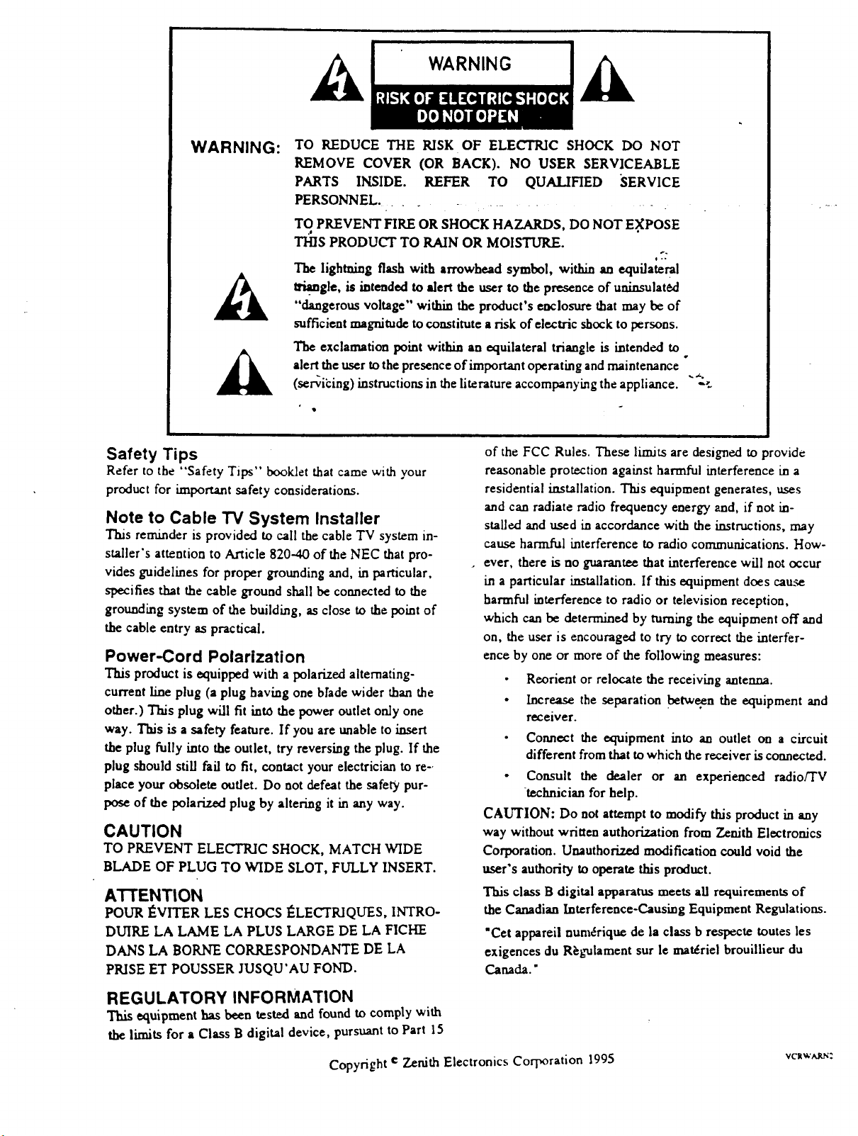
WARNING:
Safety Tips
Refer to the "Safety Tips" booklet that came with your
product for knportant safety considerations.
TO REDUCE THE RISK OF ELECTRIC SHOCK DO NOT
REMOVE COVER (OR BACK). NO USER SERVICEABLE
PARTS INSIDE. REFER TO QUALIFIED SERVICE
PERSONNEL ..............
TO PREVENT FIRE OR SHOCK HAZARDS, DO NOT E.XPOSE
THIS PRODUCT TO RAIN OR MOISTURE.
The lightning flash with arrowhead symbol, within an equilateral
I_. gle, is intended to alert the user to the presence of uninsulat6d
"dangerous voltage" within the product's enclosure that may be of
sufficient magnitude to constitute a risk of €lectric shock to persons.
The exclamation point within an equilateral triangle is intended to
alert the user to the presence of important operating and maintenance
(scribing) instructions in the literature accompanying the appliance.
Note to Cable TV System Installer
This reminder is provided to call the cable TV system in-
staller's attention to Article 820--40 of the NEC that pro-
vides guidelines for proper grounding and, in particular,
specifies that the cable ground shall be connected to the
grounding system of the building, as close to the point of
the cable entry as practical.
Power-Cord Polarization
This product is equipped with a polarized alternating-
current line plug (a plug having one bhde wider than the
other.) This plug will fit into the power outlet only one
way. This is a safety feature. If you are unable to insert
the plug fully into the outlet, try reversing the plug. If the
plug should still fail to fit, contact your electrician to re-.
place your obsolete outlet. Do not defeat the safety pur-
pose of the polarized plug by altering it in any way.
CAUTION
TO PREVENT ELECTRIC SHOCK, MATCH WIDE
BLADE OF PLUG TO WIDE SLOT, FULLY INSERT.
ATTENTION
POUR I_VITER LES CHOCS ]_LECTKIQLTES,INTRO-
DUIRE LA LAME LA PLUS LARGE DE LA FICHE
DANS LA BORNE CORRESPONDANTE DE LA
PRISE ET POUSSER JUSQU'AU FOND.
0-.
q
°
of the FCC Rules. These limits are designed to provide
reasonable protection against harmful interference in a
residential installation. This equipment generates, uses
and can radiate radio frequency energy and, if not in-
stalled and used in accordance with the instructions, may
cause harmful interference to radio communications. How-
ever, there is no guarantee that interference will not occur
in a particular installation. If this equipment does cause
harmful interference to radio or television reception,
which can be determined by turning the equipment off and
on, the user is encouraged to try to correct the interfer-
ence by one or more of the following measures:
• Reorient or relocate the receiving antenna.
• Increase the separation between the equipment and
receiver.
• Connect the equipment into an outlet on a circuit
different from that to which the receiver is connected.
• Consult the dealer or an experienced radio/TV
technician for help.
CAUTION: Do not attempt to modify this product in any
way without written authorization from Zenith Electronics
Corporation. Unauthorized modification could void the
user's authority to operate this product.
This class B digital apparatus meets all requirements of
the Canadian Interference-Causing Equipment Regulations.
"Cet appareii num_rique de la class b respecte routes les
exigences du R_gulament sur le materiel brouillieur du
Canada."
REGULATORY INFORMATION
This equipment has been tested and found to comply with
the limits for a Class B digital device, pursuant to Part 15
Copyright e Zenith Electronics Corporation 1995 vc=_.'_r_:
CONTENTS
Ill General Information
Introduction.
Installation Considerations.
1
1 Installation/Step A
VCR Setup Checklist.
"_: Connectionswithantennaora cablebox.
Audio/Video and Accessoriesconnections.
FrontAudio/Video InJacks
Ch3-4 Switch.
2 VCR Message Center/Front Controls
VCR Message Center. Overview of VCR buttons.
VCR Accessories.
III
3 Remote Control
Overview of remote keys. Install_ng Batteries; read-
ies remote to operate VCR etc.
Simple instructions for using remote.
4 VCR Features Setup/Step B
Personalize VCR On-screen Menus before playing
or recording tapes.
5 VCR/TV Displays
VCR On-Screen Display.
VCR Message Center Displays.
I
6 Watching 1V
Overview of three tuning options.
Antenna In TV Connections.
Audio/Video In TV Connections.
TV Tuning, VCR Tuning,'Cable Box Tuning.
II
7 Playing Tapes
Playing pre-recorded tapes.
Cassette Play/Record Times Chart.
Playing Tapes Options.
|
8 Instant Recording
Recording what you see on your TV screen (VCR
turnedon.)
9 Timer Recording
Recording while you are away (VCR turned off.)
L
10 Instant/Timer Recording
with a Cable. Box
Recording Cable TV (C/_,TV) subscriber program-
....ming that requires a cable/convener box.- • .......
Timer Recording broad._asts with a cable box.
I
11 VCR Plus Recording VR4185
Recording broadcast programming using the VCR
Plus feature with Cable Box control.
I
12 VCR Plus Setup VR4185/Step C
VCR must be set up before yo_ can record VCR
Plus program ming. ""_
Channel Mapping Instructions.
I
13 Additional Information
Index Search.
Real-Time Tape Counter/Memory.
Special Menu.
Auto Clock Set.
Auto Daylight Savings Adjust.
Audio Record Mode.
Audio Playback Mode.
Aux Channel.
(Audio/Video Connections-- use to enhance
audio/video performance from your VCR.)
II
14 Service Information
Operating Difficulties.
Problem Resolution Chart.
Video heads and cabinet cleaning.
15 Specifications
VCR Features Chart.
Your Sears Warranty
Warranty coverage for your VCR.
This product is exclusive to and warranted solely
by Sears. Refer to back cover for specific warranty
information.
Notes: All VCR features, graphics and identifica-
tion labeling are subject to change without prior no-
tice.
Features vary between models----not all features
listed may be available for your particular VCR.
Check VCR Features Chart.
GENERAL INFORMATION
Congratulations on buying the _ Video Cassette Recorder (VCR). For you convenience,
please read these simple Instructlons before operatlng your VCR.
NOTES:
_ ._, * ..- This Video Cassette Recorder is compatible with any video cassette bearing the mark _]_. .... - -
• _ is designed to expand yoU opportunities for in-home TV viewing and not for any usage which might violate copy-
right laws.
• ]_1_,, The Video Cassette Recorder (VCR) with this marking incorporates _ high_l_ality picture technology and
is compatible with _ Video Cassette Recorders bearing the _ mark.
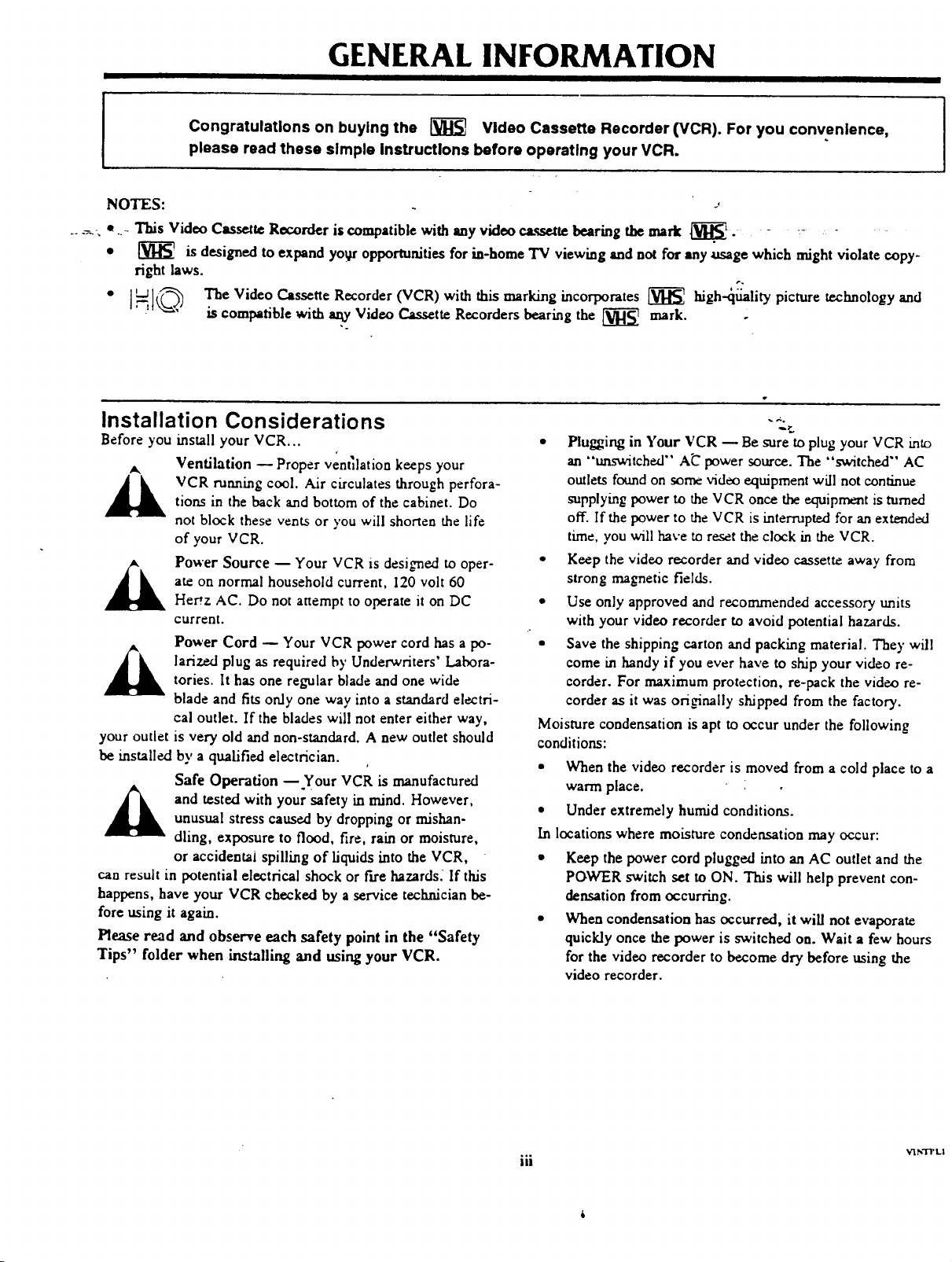
Installation Considerations
Before you install your VCR...
Ventilation -- Proper ventilation keeps your
VCR running cool. Air circulates through perfora-
tion.s in the back and bottom of the cabinet. Do
not block these vents or you will shorten the life
of your VCR.
Power Source -- Your VCR is designed to oper-
ate on normal household current, 120 volt 60
Her'z AC. Do not attempt to operate it on DC
current.
Power Cord Q Your VCR power cord has a po-
_k ariz.ed plug as required by Underwriters' Labora-
your outlet is very old and non-standard. A new outlet should
be installed by a qualified electrician.
can result in potential electrical shock or fire hazards. If this
happens, have your VCR checked by a service technician be-
fore using it again.
Please read and observe each safety point in the "Safety
Tips" folder when installing and using your VCR.
tories. It has one regular blade and one wide
blade and fits only one way into a standard electri-
cal outlet. If the blades will not enter either way,
Safe Operation -- Your VCR is manufactured
and tested with your safety in mind. However,
unusual stress caused by dropping or mishan-
dling, exposure to flood, fire, rain or moisture,
or aceidentai spilling of liquids into the VCR,
"
• Plugging in Your VCR -- Be sure to plug your VCR mt_
an "_tched" A_ power source. The "switched" AC
outlets found on some video equipment will not continue
supplying power to the VCR once the equipment is turned
off. If the power to the VCR is interrupted for an extended
time, you will have to reset the clock in the VCR.
• Keep the video recorder and video cassette away from
strong magnetic fields.
• Use only approved and recommended accessory units
with your video recorder to avoid potential hazards.
• Save the shipping carton and packing material. The)"will
come in handy if you ever have to ship your video re-
corder. For maximum protection, re-pack the video re-
corder as it was ori_nally shipped from the factory.
Moisture condensation is apt to occur under the following
conditions:
• When the video recorder is moved from a cold place to a
warm place.
• Under extremely humid conditions.
In locations where moisture condensation may occur:
• Keep the power cord plugged into an AC outlet and the
POWER switch set to ON. This will help prevent con-
densation from occurring.
• When condensation has occurred, it will not evaporate
quickly once the power is switched on. Wait a few hours
for the video recorder to become dry before using the
video recorder.
iii
V]N']T L|
INSTALLATION
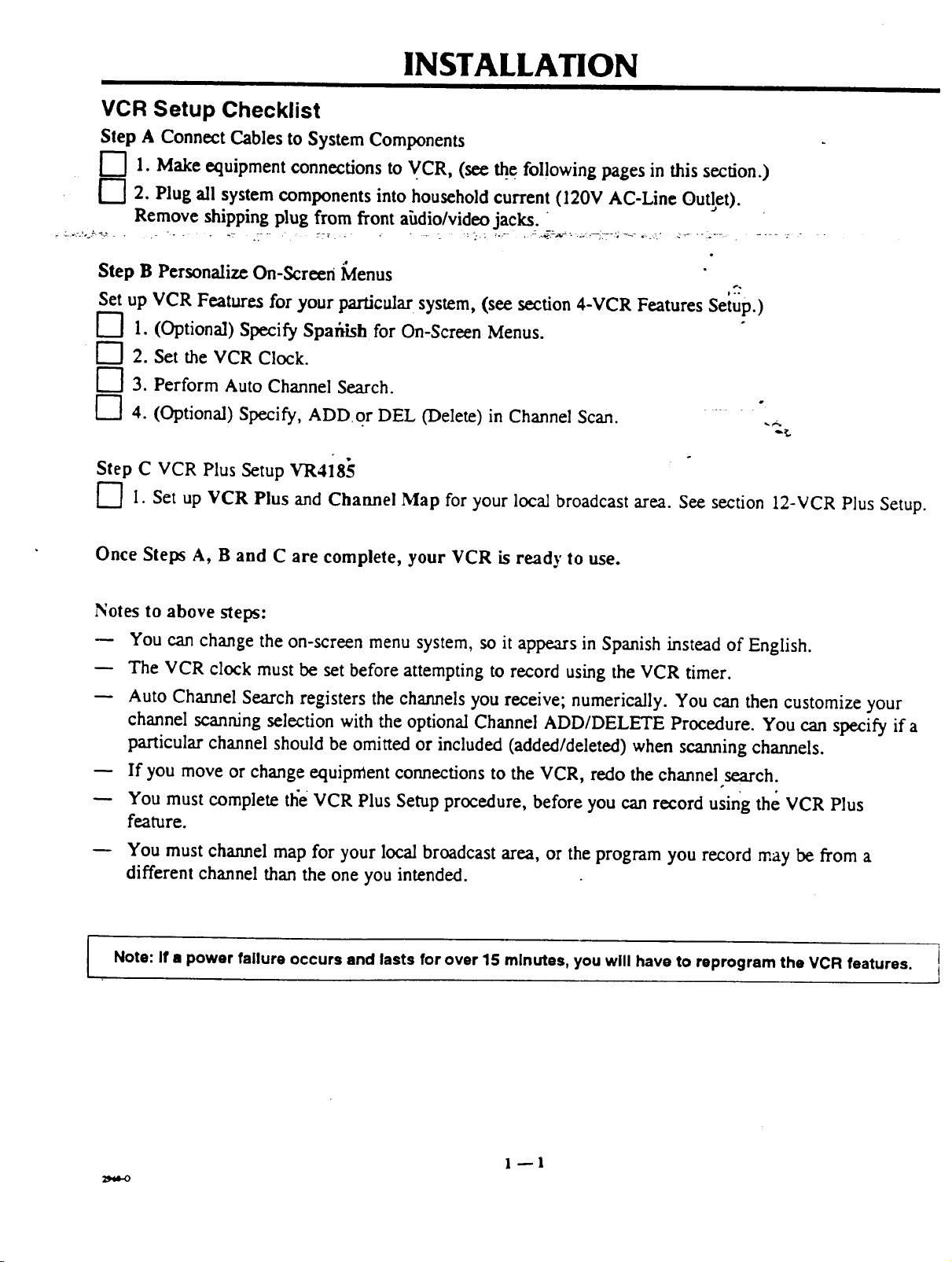
VCR Setup Checklist
Step A Connect Cables to System Components
["7 1. Makeequipment connectionsto VCR, (see _e fol!owingpages in this section.)
['7 2. Plug all system components into householdcurrent(120V AC-Line Outlet).
:-:.!'-_"::."- '- " _:" .T'" :::7 _ ,.... _ :-.-,: _-.'" , :.._:-_'_--"'_i7 "':'_" "=--_' _'_ "':_"_' . ..... "_ "
Remove shipping plug fromfrontahdio/video jacks.
.e
Step B PersonalizeOn-Screen Menus
Set up VCR Features for yourparticular system, (see section 4-VCR Features Setup.)
[--] 1. (Optional) Specify Spafiish for On-Screen Menus.
[--'] 2. Set the VCR Clock.
["7 3. PerformAuto Channel Search.
[-"] 4. (Optional) Specify, ADD or DEL (Delete) in Channel Scan. -
Step C VCR Plus Setup VR4185
F']I. Set up VCR Plus and Channel Map for your local broadcast area. See section 12-VCR Plus Setup.
Once Steps A, B and C are complete, your VCR is ready to use.
Notes to above steps:
You can change the on-screen menu system, so it appears in Spanish instead of English.
The VCR clock must be set before attempting to record using the VCR timer.
Auto Channel Search registers the channels you receive; numerically. You can then customize your
channel scanning selection with the optional Channel ADD/DELETE Procedure. You can specify if a
particular channel should be omitted or included (added/deleted) when scanning channels.
If you move or change equipment connections to the VCR, redo the channel search.
You must complete the VCR Plus Setup procedure, before you can record using the VCR Plus
feature.
You must channel map for your local broadcast area, or the program you record may be from a
different channel than the one you intended.
Note: If • power failure occurs and lasts for over 15 minutes, you will have to reprogram the VCR features. ]
J
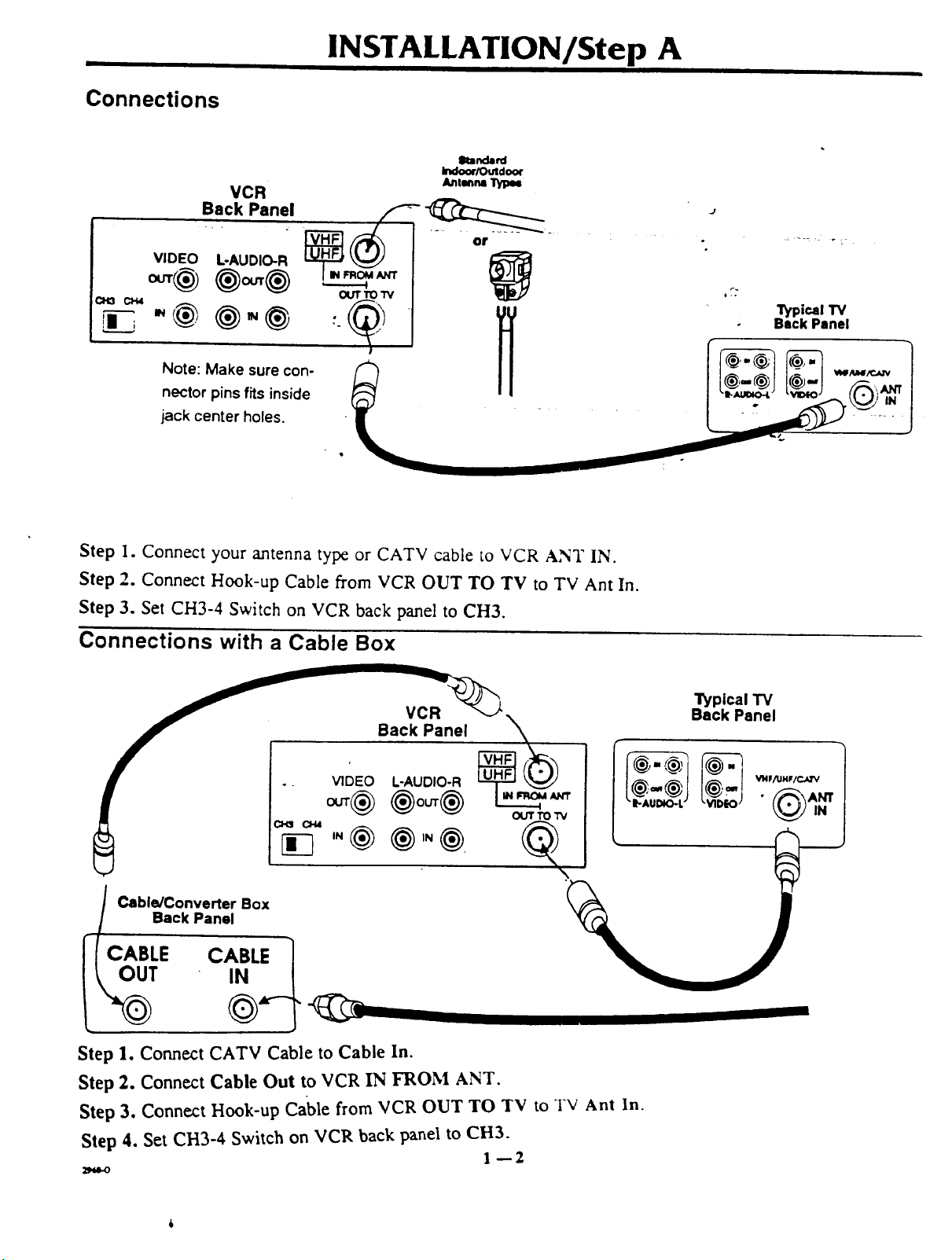
Connections
VCR
Back Panel
INSTALLATION/Step A
elumda_d
Indoo¢/Outdoor
A_nl_n=
VIDEO
L-AUDIO-R
ou'r TO I"V
"@
Note: Make sure con-
nector pins fits inside
jack center holes.
Step 1. Connect your antenna type or CATV cable to VCR ANT IN.
Step 2. Connect Hook-up Cable from VCR OUT TO TV to TV Ant In.
Step 3. Set CH3-4 Switch on VCR back panel to CH3.
Connections with a Cable Box
Back Panel
"i_pical TV
Back Panel
_ _ ou'r TO 1_
Cable/Converter Box
Back Panel
Step 1. Connect CATV Cable to Cable In.
Step 2. Connect Cable Out to VCR IN FROM ANT.
Step 3. Connect Hook-up Cable from VCR OUT TO TV to TV Ant In.
Step 4. Set CH3-4 Switch on VCR back panel to CH3.
1--2
INSTALLATION/Step A
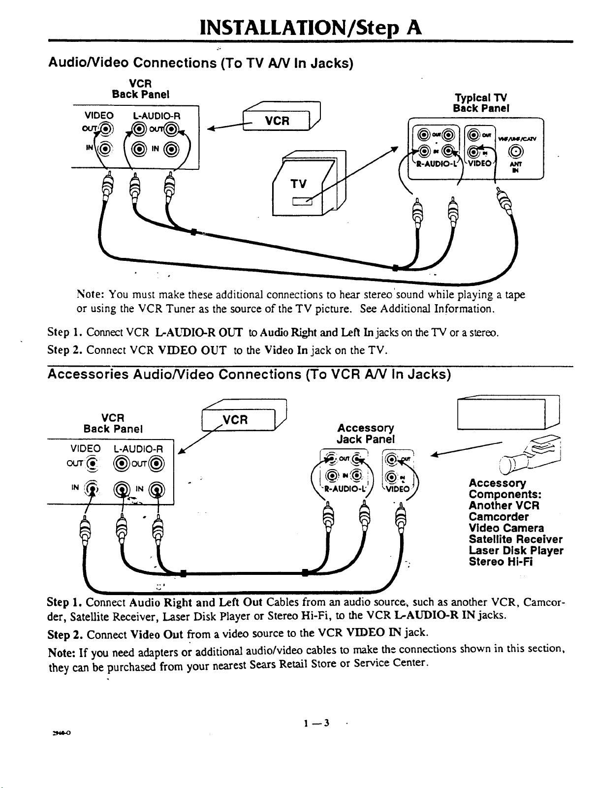
Audio/Video Connections (To TV A/V In Jacks)
VCR
Back Panel
Note: You must make these additional connections to hear stereo sound while playing a tape
or using the VCR Tuner as the source of the TV picture. See Additional Information.
Typical TV
Back Panel
_lf/ul4/c_-v
/u_rr
IN
Step 1. Connect VCR L-AUDIO-R OUT to Audio Right and Left In jacks on the TV or a stereo.
Step 2. Connect VCR VIDEO OUT to the Video In jack on the TV.
Accessories Audio/Video Connections (To VCR A/V In Jacks)
Back Panel ,,,.VCR
VCR _,.
VIDEO L-AUDIO-R
IN
Step 1. Connect Audio Right and Left Out Cables from an audio source, such as another VCR, Camcor-
der, Satellite Receiver, Laser Disk Player or Stereo Hi-Fi, to the VCR L-AUDIO-R IN jacks.
z
Accessory
Jack Panel
I
Accessory
Components:
Another VCR
Camcorder
Video Camera
Satellite Receiver
Laser Disk Player
Stereo Hi-Fi
Step 2. Connect Video Out from a video source to the VCR VIDEO IN jack.
Note: If you need adapters or additional audio/video cables to make the connections shown in this section,
they can be purchased from your nearest Sears Retail Store or Service Center.
1--3
INSTALLATION/Step A
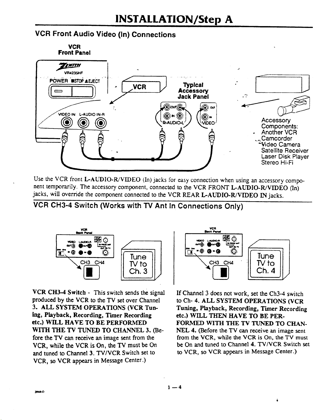
VCR Front Audio Video (In) Connections
VCR
Front Panel
.... POWER _ISTOp&EJECT -" . _,-
l_plcel
Accessory
Jack Panel
_-R
®®®
,7: /_
Accessory
Components:
• Another VCR
._.Camcorder
-Video Camera
Satellite Receiver
Laser Disk Player
Stereo Hi-Fi
J
Use the VCR front L-AUDIO-R/VIDEO (In)jacks for easy connection when using an accessory compo-
nent temporarily. The accessory component, connected to the VCR FRONT L-AUDIO-R/VIDEO (In)
jacks, will override the component connected to the VCR REAR L-AUDIO-R/VIDEO IN jacks.
VCR CH3-4 Switch (Works with TV Ant In Connections Only)
VCR
loclt IJw_l
to
h. 3
VCR CH3-4 Switch - This switch sends the signal
produced by the VCR to the TV set over Channel
3. ALL SYSTEM OPERATIONS (VCR Tun-
hag, Playback, Recording, Timer Recording
etc.) WILL HAVE TO BE PERFORMED
WITH THE TV TUNED TO CHANNEL 3. (Be-
fore the TV can receive an image sent from the
VCR, while the VCR is On, the TV must be On
and tuned to Channel 3. TV/VCR Switch set to
VCR, so VCR appears in Message Center.)
If Channel 3 does not work, set the Ch3-4 switch
to Ch- 4. ALL SYSTEM OPERATIONS (VCR
Tuning, Playback, Recording, Timer Recording
etc.) WILL THEN HAVE TO BE PER-
FORMED WITH THE TV TUNED TO CHAN-
NEL 4. (Before the TV can receive an image sent
from the VCR, while the VCR is On, the TV must
be On and tuned to Channel 4. TV/VCR Switch set
to VCR, so VCR appears in Message Center.)
1--4
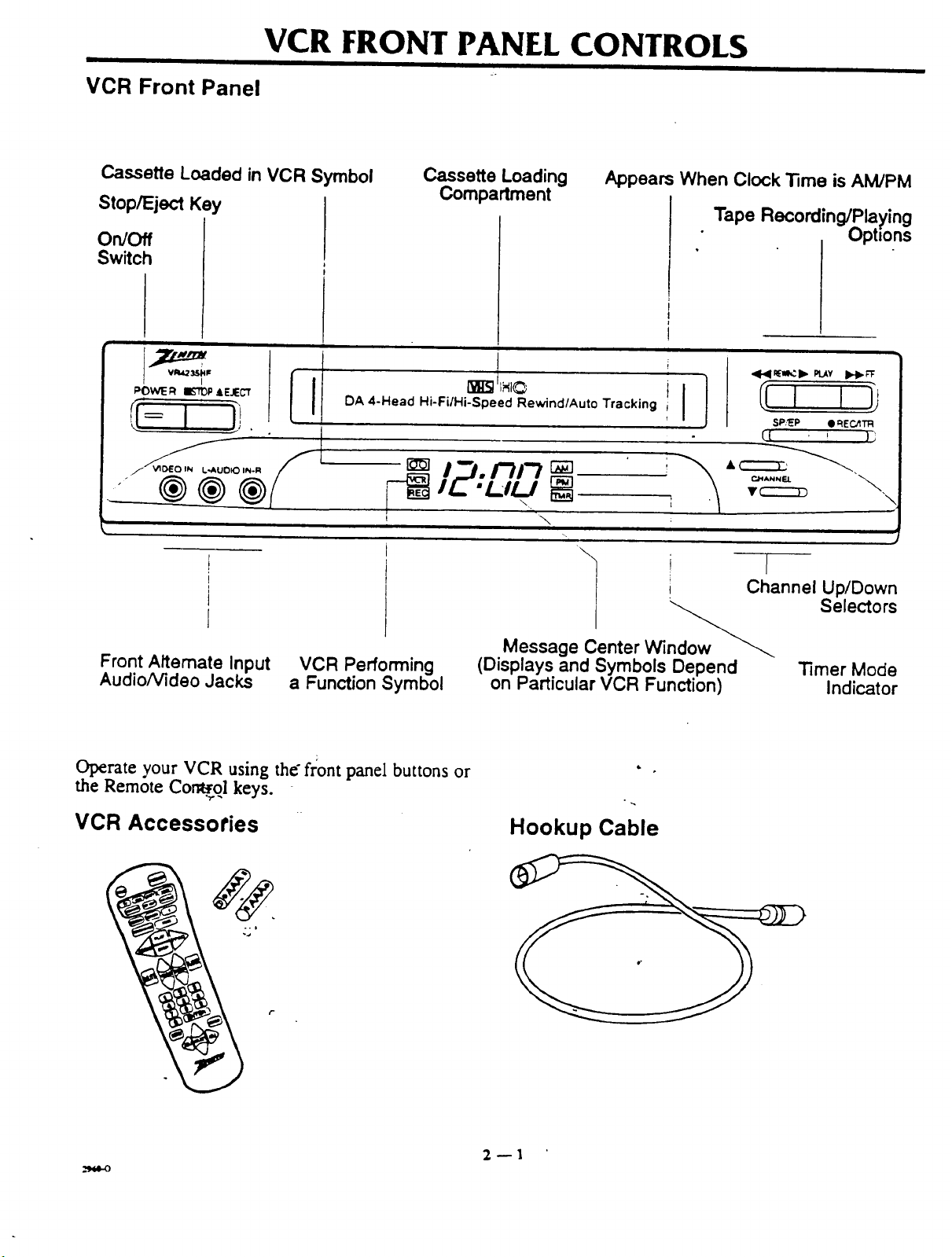
VCR Front Panel
VCR FRONT PANEL CONTROLS
Cassette Loaded in VCR Symbol
Stop/Eject Key
On/Off
Switch
i
DA 4-Head Hi-FilHi-Speed Rewind/Auto Tracking i
Cassette Loading
Compartment
I:/./-/I'7
i
Appears When Clock Time is AM/PM
Tape Recording/Playing
Ophons
J
i}
,ql.41_=_:!,,"PLAY),.I,._
SP?EP • _EC,'tTR
({ ' }j
C_ANNEL
T C:::::::::::D
\ I
Channel Up/Down
Selectors
Front Alternate Input
Audio, Video Jacks
Operate your VCR using the" front panel buttons or
the Remote Cor_.ol keys.
VCR Performing
a Function Symbol
VCR Accessories
Message Center Window_"_
(Displays and Symbols Depend Timer Mode
on Particular VCR Function) Indicator
Hookup Cable
2--1
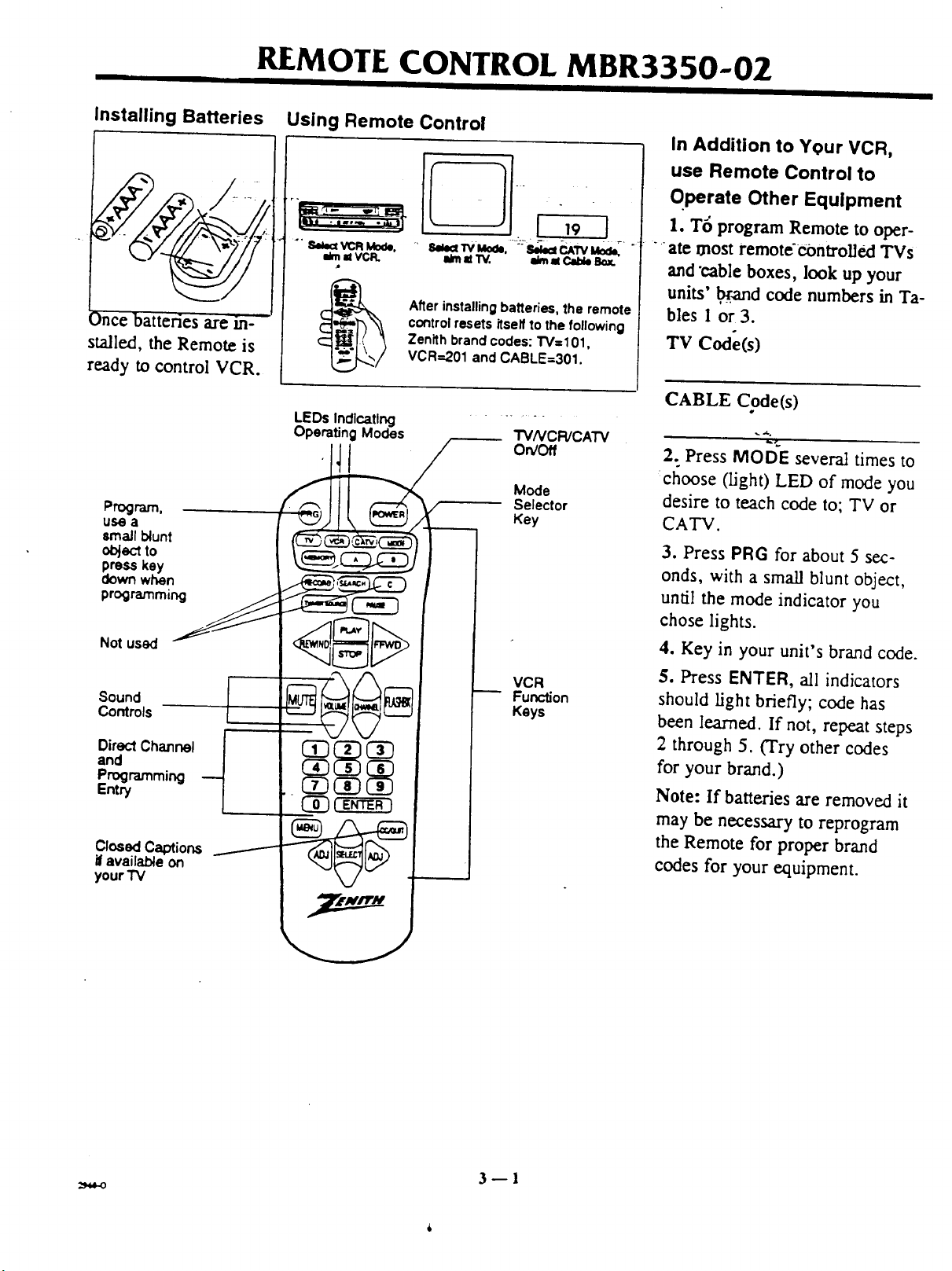
REMOTE CONTROL MBR3350-02
I II I I I
Installing Batteries Using Remote Control
r-
.4
_)nce batteries are in--
stalled, the Remote is
..... 8I_IV'Mo_, -'bI_CAWMo_
After installing batteries, the remote
control resets itself to the following
Zenith brand codes: TV=101,
VCR=201 and CABLE=301.
ready to control VCR.
LEDs Indlcatlng
Operating Modes
Program.
use a
small blunt
object to
press key
down when
programming
i_ =t W. eJmMCab_ Bo_.
TVNCR/CATV
On/Off
Mode
Selector
Key
In Addition to Your VCR,
use Remote Control to
Qperate Other Equipment
I. T6 program Remote to oper-
ate most remote'€ontroUed TVs
and "cable boxes, look up your
units' _and code numbers in Ta-
bles 1 or 3.
Tv Code(s)
CABLE Code(s)
_¢..
2. Press MODE several times to
:choose (light) LED of mode you
desire to teach code to; TV or
CATV.
3. Press PRG for about 5 sec-
onds, with a small blunt object,
until the mode indicator you
chose lights.
Not used
Sound
Controls
DirectChannel
and
Programming
Entry
ClosedCaptions
ifavailable on
your "IV
VCR
Function
Keys
4. Key in your unit's brand code.
5. Press ENTER, all indicators
should light briefly; code has
been learned. If not, repeat steps
2 through 5. (Try other codes
for your brand.)
Note: If batteries are removed it
may be necessary to reprogram
the Remote for proper brand
codes for your equipment.
3fl
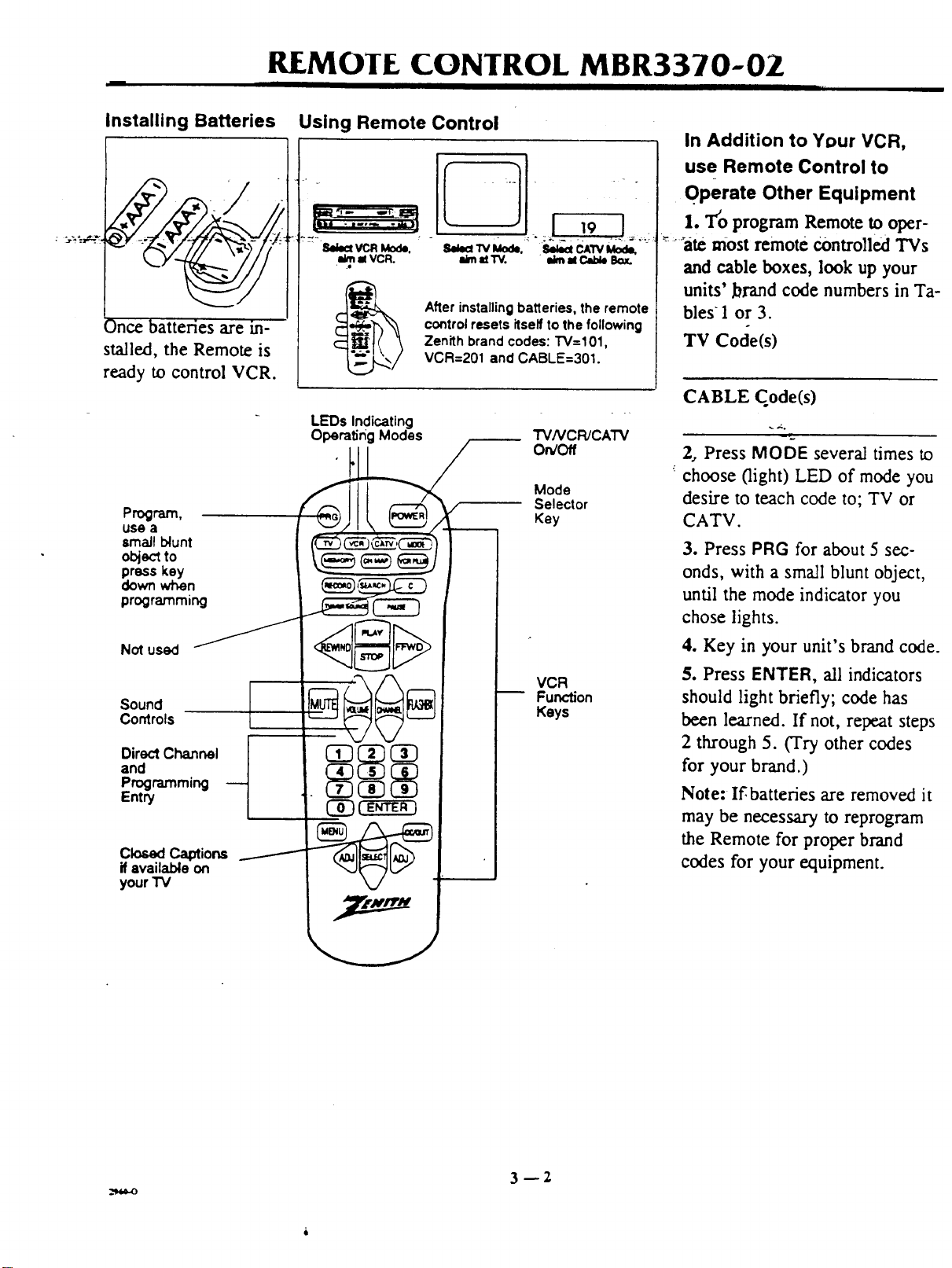
REMOIE CONTROL MBR3370-OZ
Installing Batteries
¢S ate m-
stalled, the Remote is
Using Remote Control
llelect VCR Mode.
el VCR.
Afler installing batleries, the remote
control resets itself to the following
Zenith brand codes: "1"V=101,
VCR=201 and CABLE=301.
ready to control VCR.
LEDs Indicating
OperatingModes
Program,
usea _/ I "_."_"_Z
lmaJl blunt (_)_ c_--'C__) I I
obj_:_to _,_ c;-_ _,,_ / I I
press key _--_ "_" "_-'J I I
programm,ng _ _ I
i_midW. ilim al Clide Box.
TV/VCR/CATV
On/Off
Mode
Selector
Key
In Addition to Your VCR,
use Remote Control to
OPerate Other Equipment
1. T'o program Remote to oper-
_ :'-'ate most remote Controlled TVs
and cable boxes, look up your
units' brand code numbers in Ta-
bles 1 or 3.
TV Code(s)
CABLE Code(s)
2, Press MODE several times to
choose (light) LED of mode you
desire to teach code to; TV or
CATV.
3. Press PRG for about 5 sec-
onds, with a small blunt object,
until the mode indicator you
chose lights.
Direct Channel I 03 I
and
your i v M/
VCR
Function
Keys
4. Key in your unit's brand code.
5. Press ENTER, all indicators
should light briefly; code has
been learned. If not, repeat steps
2 through 5. (Try other codes
for your brand.)
Note: If,batteries are removed it
may be necessary to reprogram
the Remote for proper brand
codes for your equipment.
3--2
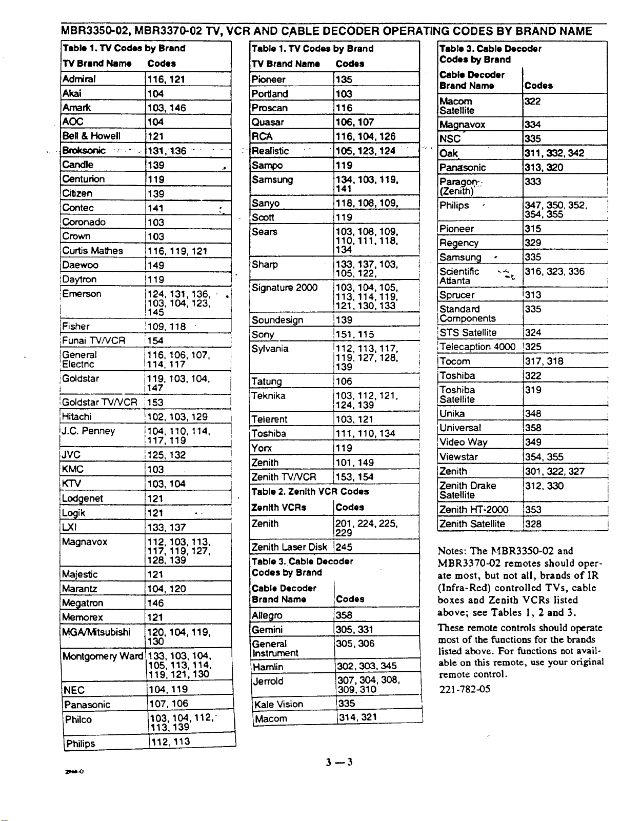
MBR3350-02, MBR3370-02 "FV,VCR AND C,ABLE DECODER OPERATING CODES BY BRAND NAME
Table 1. TV Codes by Brand Table 1. TV Codes by Brand Table 3. Cable Decoder
TV Brand Name Codes
Admiral 116, 121
Akai 104
Amark 103, 146
AOC 104
Bell & Howell 121
Bmksonic _.:._ . 131,136 .......
Candle 139 .,
Centurion 119
Citizen 139
Contec :141 •
Coronado 103
Crown 103
Curtis Mathes 116, 119, 121
Daewoo J149
IDaytron il 19
L
iEmerson 124, 131,136, • .
J 145
Fisher 109, 118
iFunai TV/VCR 154
General 116, 106, 107,
Electdc 114, 117
iGoldstar i119, 103, 104,
t 1147
IGoldstar "I'V/VCR 1153
Hitachi 1102,103, 129
J.C. Penney !117,119t104'110, 114,
JVC ',125, 132
KMC 1103
KTV 103,
LodQenet 121
Locjik 121
L.XI 133,
Magnavox 112,
Majestic
Marantz
Megatron
Memorex
MGNMitsubishi
MontgomeryWard
NEC
Panasonic
iPhilco
Philips
I
103, 104, 123,
i
I
104
137
103, 113,
117, 119, 127,
128, 139
121
104, 120
146
121
120, 104, 119,
130
,133, 103, 104,
105, 113, 114,
119, 121,130
104,119
,107, 106
103, 104,
113, 139
112,113
"x
112,"
TV Brand Name Codes
Pioneer
Por'dand
)roscan
Quasar 107
RCA 104,126
Realistic - 123, 124 : - -
Sampo
Samsung 103, 119,
Sanyo 108, 109,
Scott
Sears 108,109,
Sharp
Signature 2000
Soundesign
Sony 115
Sylvania 113, 117,
Tatung
Teknika 121,
I
i
I
Telerent
Toshiba 134
Yorx
Zenith
Zenith "rv/vcR
Table 2. Zenith VCR Codes
Zenith VCRs Codes
Zenith 201,224, 225,
Zenith Laser Disk 245
Table 3. Cable Decoder
Codes by Brand
Cable Decoder
Brand Name Codes
Allegro
Gemini
General
135
103
116
106,
116,
105,
119
134,
141
118,
119
103,
110,
134
133,
105,
103,
113,
121,
139
1151,
!
!112,
119,
139
t106
103, 112,
124, 139
103, 121
111,110,
119
101,149
153, 154
229
358
305,331
305,306
111,118,
137, 103,
122,
104,105,
114,119,
130, 133
127, 128,
Instrument
Hamlin
Jerrold
-Kale Vision 335
_lacom 1314, 321
302,303,345
307,304,308,
309,310
3--3
Codes by Brand
;able Decoder
Irand Name
Macom
Satellite
Mag_vox
NSC
Oak,
Panasonic
)aragon::
Zenith)'
Philips
Pioneer 315 ;
Regency 329 I
Samsung o 335
Scientific _._. 316, 323,336
AtJanta ":
i
Sprucer !313
Components
J
Standard !335
iSTS Satellite 324
Telecaption 4000 !325
ITocom 1317,318
'Toshiba
Satell te
Universal
Video Way
Viewstar
4
Zenith
Zenith Drake
Codes
322
334
335
3111 332, 342
313, 320
347, 350, 352, !
354, 355
!
349
354, 355
301,322, 327
312, 330
Satellite
Zenith HT-2000
Zenith Satellite
353
328
Notes: The MBR3350-02 and
MBR3370-02 remotes should oper-
ate most, but not all, brands of IR
(Infra-Red) controlled TVs, cable
boxes and Zenith VCRs listed
above; see Tables 1, 2 and 3.
These remote controls should operate
most of the functions for the brands
listed above. For functions not avail-
able on this remote, use your original
remote control.
221-782-05
I
L
I
J
i
!
 Loading...