

Page 1

© Copyright 2003, Zenith Electronics Corporation
Installation and Operating Guide | Warranty
Model Numbers | VCS342 • VCM322 | Video Cassette Recorders
Page 2
Safety Precautions
This lightning flash with arrowhead symbol
within an equilateral triangle is intended to
alert the user to the presence of uninsulated
dangerous voltage within the product’s enclosure that may be of sufficient magnitude to constitute a
risk of electric shock to persons.
The exclamation point within an equilateral
triangle is intended to alert the user to the
presence of important operating and mainte-
nance (servicing) instructions in the literature
accompanying the product.
NOTE TO CABLE/TV INSTALLER: This reminder is provided
to call the cable TV system installer’s attention to Article
820-40 of the National Electric Code (U.S.A.). The code
provides guidelines for proper grounding and, in particular,
specifies that the cable ground shall be connected to the
grounding system of the building, as close to the point of
the cable entry as practical.
REGULATORY INFORMATION:
FCC Part 15
This product has been tested and found to comply with
the limits for a Class B digital device, pursuant to Part 15
of the FCC Rules. These limits are designed to provide
reasonable protection against harmful interference when
the product is operated in a residential installation. This
product generates, uses and can radiate radio frequency
energy and, if not installed and used in accordance with
the instruction manual, may cause harmful interference to
radio communications. However, there is no guarantee
that interference will not occur in a particular installation. If this product does cause harmful interference to
radio or television reception, which can be determined by
turning the product off and on, the user is encouraged to
try to correct the interference by one or more of the
following measures:
• Reorient or relocate the receiving antenna.
•Increase the separation between the product and
receiver.
• Connect the product into an outlet on a circuit
different from that to which the receiver is
connected.
• Consult the dealer or an experienced radio/TV technician for help.
FCC WARNING: This equipment may generate or use radio
frequency energy. Changes or modifications to this
equipment may cause harmful interference unless the
modifications are expressly approved in the instruction
manual. The user could lose the authority to operate this
equipment if an unauthorized change or modification is
made.
FCC COMPLIANCE: The responsible party for this product’s
compliance is:
Zenith Electronics Corporation, 2000 Millbrook Drive,
Lincolnshire, IL 60069, USA
Phone: 1-847-941-8000.
IMPORTANT COPYRIGHT INFORMATION: Many television
programs and films are copyrighted. In certain circumstances copyright law may apply to private in-home video
taping of copyrighted materials.
WARNING
2
RISK OF ELECTRIC SHOCK
DO NOT OPEN
CAUTION: TO PREVENT ELECTRIC SHOCK, MATCH WIDE
BLADE OF PLUG TO WIDE SLOT, FULLY INSERT.
ATTENTION: POUR ÉVITER LES CHOC ÉLECTRIQUES,
INTRODUIRE LA LAME LA PLUS LARGE DE LA FICHE DANS
LA BORNE CORRESPONDANTE DE LA PRISE ET POUSSER
JUSQU’AU FOND.
WARNING: Do not drop the power cord tying band into
the unit. Doing so might cause a fire or an electrical
shock. (See page 10.)
WARNING: TO REDUCE THE RISK OF FIRE OR ELECTRIC
SHOCK, DO NOT EXPOSE THIS PRODUCT TO RAIN OR
MOISTURE.
MOISTURE CONDENSATION
If you pour a cold liquid into a glass, water vapor in the
air will condense on the surface of the glass. This is
moisture condensation. Moisture condensation on the
head drum, one of the most crucial parts of the unit,
will cause damage to the tape. When the VCR is exposed
to a rapid temperature change from cold to warm, some
condensation will occur. Under this condition, connect
the power cord to the AC line, press POWER on and
allow at least two hours for the VCR to dry out.
WARNING: TO REDUCE THE RISK
OF ELECTRIC SHOCK
DO NOT REMOVE COVER (OR BACK)
NO USER-SERVICEABLE PARTS INSIDE
REFER SERVICING TO QUALIFIED SERVICE
PERSONNEL.
SERIAL NUMBER: The serial number is found on the back
of this unit. This number is unique to this unit and not
available to others. You should record requested information here and retain this guide as a permanent record of
your purchase.
Model No. ___________________________
Serial No. ___________________________
Page 3
3
CONTENTSFEATURES
INTRODUCTION
Features/Contents/Accessories . . . . . . . . . . . . . . . . . .3
Important Safety Instructions . . . . . . . . . . . . . . . . . . . .4
VCR Features Chart . . . . . . . . . . . . . . . . . . . . . . . . . .5
VCR SETUP
Connections for Your VCR . . . . . . . . . . . . . . . . . . . .6-7
Control Names and Locations . . . . . . . . . . . . . . . .8-10
Remote Control . . . . . . . . . . . . . . . . . . . . . . . . . .11-12
Onscreen Display (OSD) . . . . . . . . . . . . . . . . . . . . . .13
Setting the Onscreen Menus . . . . . . . . . . . . . . . . . . .14
Setup Menu Features and Operation . . . . . . . . . . . . .15
Channel/Source Selection . . . . . . . . . . . . . . . . . .16-17
Viewing TV Only . . . . . . . . . . . . . . . . . . . . . . . . . . . .17
Video Cassette Tapes . . . . . . . . . . . . . . . . . . . . . . . .18
Setting the Clock . . . . . . . . . . . . . . . . . . . . . . . . .19-20
PLAYBACK
Normal Playback . . . . . . . . . . . . . . . . . . . . . . . . .21-22
Special Effects Playback . . . . . . . . . . . . . . . . . . .23-24
RECORDING
Normal Recording . . . . . . . . . . . . . . . . . . . . . . . . . . .25
Timer Recording . . . . . . . . . . . . . . . . . . . . . . . . . .26-28
Instant Timer Recording . . . . . . . . . . . . . . . . . . . . . .29
Dubbing and Editing . . . . . . . . . . . . . . . . . . . . . . . . .30
ADDITIONAL INFORMATION
EZ Functions . . . . . . . . . . . . . . . . . . . . . . . . . . . . . . .31
VHS Hi-Fi Stereo System/MTS Broadcast . . . . . .32-33
Tape Counter Memory Feature . . . . . . . . . . . . . . . . .34
Editing a Recording . . . . . . . . . . . . . . . . . . . . . . . . . .35
Operating Hints . . . . . . . . . . . . . . . . . . . . . . . . . . . . .35
Video Head Cleaning . . . . . . . . . . . . . . . . . . . . . . . .35
Troubleshooting . . . . . . . . . . . . . . . . . . . . . . . . . . . .36
Specifications . . . . . . . . . . . . . . . . . . . . . . . . . . . . . .37
Warranty . . . . . . . . . . . . . . . . . . . . . . . . . . .Back Cover
• Auto Clock Set System
• Energy Save Function
• Easy Operations
• MTS Hi-Fi Stereo
•1 Year/8 Event Timer with
DAILY and WEEKLY
Functions
• Auto Power and Playback
Functions
• Instant Timer Recording
• Real-Time Tape Counter,
Tape Remaining Time
• Clean Still, Slow, Frame
Advance, Commercial Skip
• Auto Tracking Function/Auto
Head Cleaner
• Onscreen Function Display
•Trilingual Onscreen
Programming Menus
(English/Spanish/French)
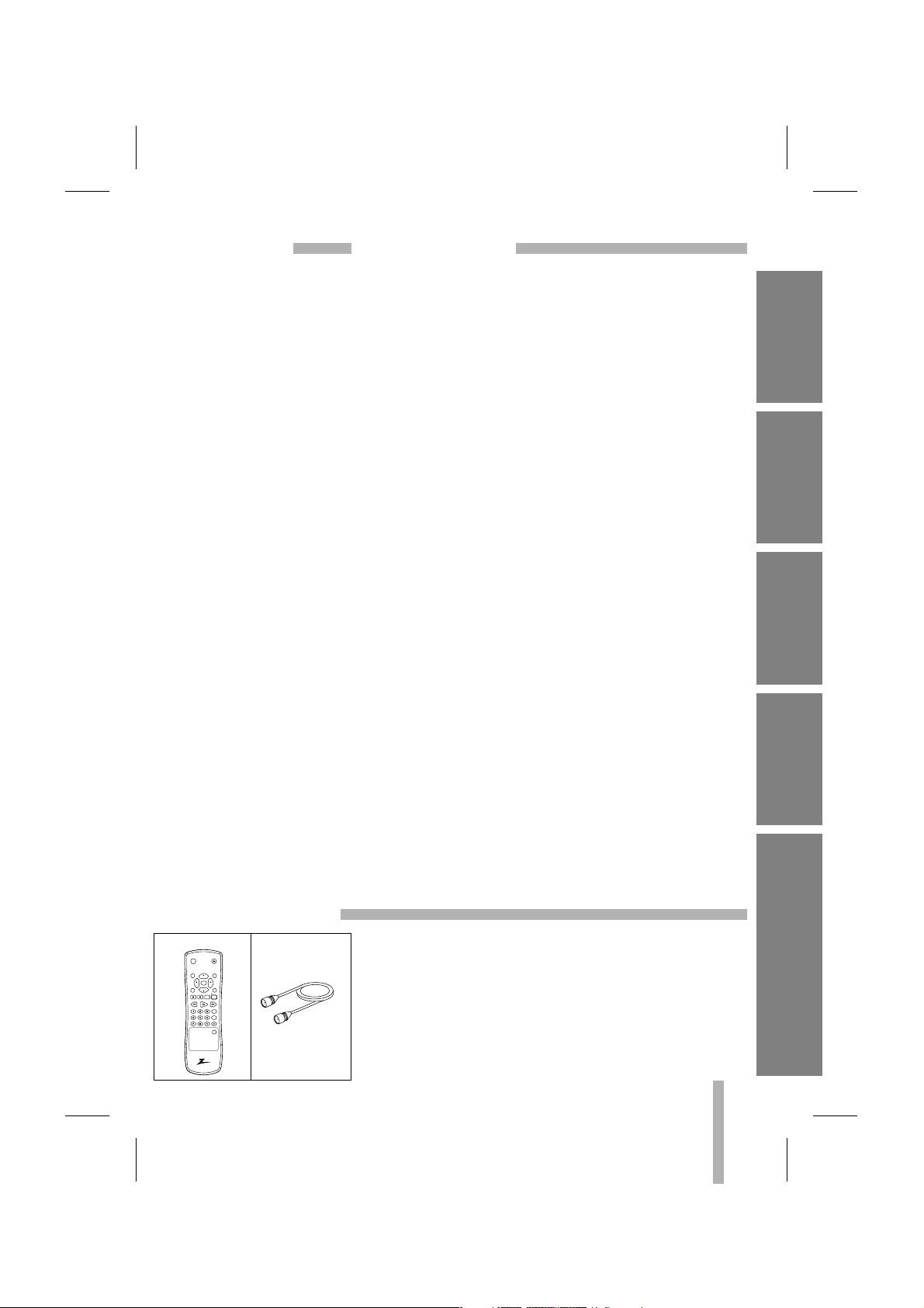
Check to make sure that all accessories listed left have been
included with your VCR.
•
Depending on your antenna system, you may need a different
type of Combiner (Mixer) or Separator (Splitter). These are available at most electronics stores. For further details, see your nearest authorized service center.
ACCESSORIES
INTRODUCTION
VCR SETUP PLAYBACK
RECORDING ADDITIONAL INFORMATION
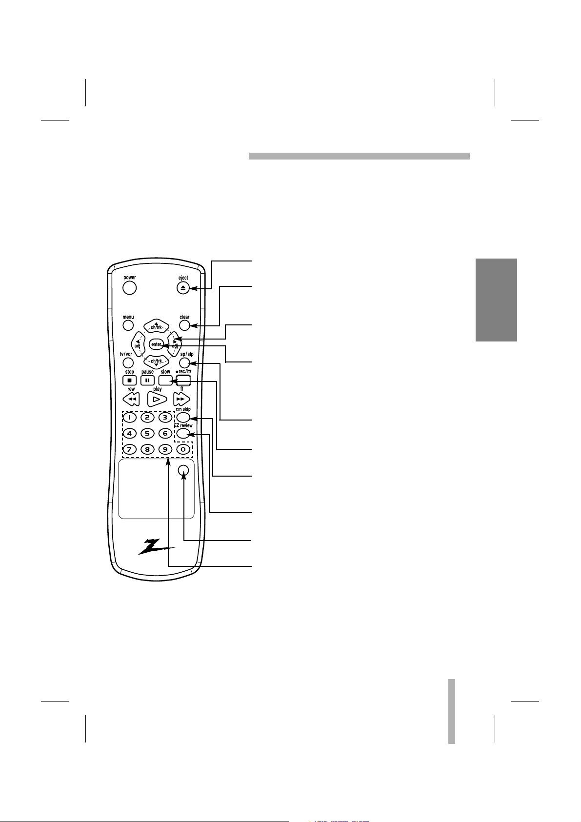
Remote Control RF Coaxial Cable
power
eject
menu clear
ch/trk
enter
adj
adj
sp / slptv / vcr
ch/trk
rec / itr
stop
pause slow
rew play ff
cm skip
EZ review
input
Page 4

4
INTRODUCTION
IMPORTANT SAFETY INSTRUCTIONS
1. Read these instructions. - All these safety and
operating instructions should be read before the
product is operated.
2. Keep these instructions. - The safety, operating
and use instructions should be retained for future
reference.
3. Heed all warnings. - All warnings on the product
and in the operating instructions should be
adhered to.
4. Follow all instructions. - All operating and use
instructions should be followed.
5. Do not use this product near water. – For
example: near a bath tub, wash bowl, kitchen
sink, laundry tub, in a wet basement; or near a
swimming pool; and other areas located near
water.
6. Clean only with dry cloth. – Unplug this product
from the wall outlet before cleaning. Do not use
liquid cleaners.
7.
Do not block any ventilation openings. Install in
accordance with the manufacturer’s instructions. -
Slots and openings in the cabinet are provided for ventilation and to ensure reliable operation of the product and to protect it from overheating. The openings should never be blocked
by placing the product on a bed, sofa, rug or
other similar surface. This product should not be
placed in a built-in installation such as a bookcase or rack unless proper ventilation is provided
or the manufacturer’s instructions have been
adhered to.
8. Do not install near any heat sources such as
radiators, heat registers, stoves, or other
apparatus (including amplifiers) that produce
heat.
9. D
o not defeat the safety purpose of the polarized or grounding-type plug. A polarized plug
has two
blades with one wider than the other.
A grounding
type plug has two blades and a
third grounding prong. The wide blade or the
third prong are provided for your safety. If the
provided plug does not fit into your outlet,
consult an electrician for replacement of the
obsolete outlet.
10. Protect the power cord from being walked
on or pinched particularly at plugs, convenience receptacles, and the point where
they exit from the product.
11. Only use attachments/accessories specified
by the manufacturer.
12. Use only with the cart, stand, tripod, bracket, or table specified by the manufacturer, or
sold with apparatus. When a cart is used,
use caution when moving the cart/product
combination to avoid injury from tip-over.
13. Unplug this product during lightning storms
or when unused for long periods of time.
14.
Refer all servicing to qualified service personnel.
Servicing is required when the product has been damaged in any way, such as
power-supply cord or plug is damaged, liquid has been spilled or objects have fallen
into the product, the product has been
exposed to rain or moisture, does not operate normally, or has been dropped.
PLEASE READ AND OBSERVE ALL WARNINGS AND INSTRUCTIONS IN THIS OWNER’S
MANUAL. AND THOSE MARKED ON THE PRODUCT. RETAIN THIS BOOKLET FOR FUTURE
REFERENCE.
This product has been designed and manufactured to assure personal safety. Improper use can result in
electric shock or fire hazard. The safeguards incorporated in this product will protect you if you observe the
following procedures for installation, use, and servicing.
This product does not contain any parts that can be repaired by the user.
DO NOT REMOVE THE CABINET COVER, OR YOU MAY BE EXPOSED TO DANGEROUS VOLTAGE.
REFER SERVICING TO QUALIFIED SERVICE PERSONNEL ONLY.
Page 5
5
INTRODUCTION
VCR FEATURES CHART
This page shows the features of your VCR and the differences between the models.
FEATURES VCS342 VCM322
4-Heads (Special Video Effects) Yes Yes
Full Load/Quick Start Yes Yes
Auto Head Cleaner Yes Yes
Audio System MTS Hi-Fi Stereo Monaural
Audio/Video (A/V) Jacks Stereo Monaural
Remote Control Yes Yes
Auto/Manual Band Select Yes Yes
Auto/Manual Channel Search Yes Yes
Channel Capability (CATV & TV) 181 181
Record Speeds SP/SLP Yes Yes
Playback Speeds SP/LP/SLP Yes Yes
Auto Playback System Yes Yes
Auto/Manual Digital Tracking Yes Yes
Instant Recording Yes Yes
Timer-Controlled Recording Yes Yes
Auto Playback Tape Speed Adjust Yes Yes
Slow-Motion Video (4-head VCR) Yes (1/19) Yes (1/19)
Pause/Still Video Clear Clear
Real-Time Tape Counter Yes Yes
Visual Search Yes Yes
Logic Search Yes Yes
CM Skip Yes Yes
English/Spanish/French Menus Yes Yes
1-Year, 8-Event Timer Yes Yes
Message Center Front Panel Display Yes Yes
Easy Power On Yes Yes
Easy Review Yes Yes
Easy Information Yes Yes
Auto Clock Set System Yes Yes
Hook-up Cable (VCR to TV) Yes Yes
Energy Saving Yes Yes
1. Model VCS342 is used for the description, operation, and details provided in this
operating guide.
2. VCR design and specifications are subject to change without prior notice.
Page 6
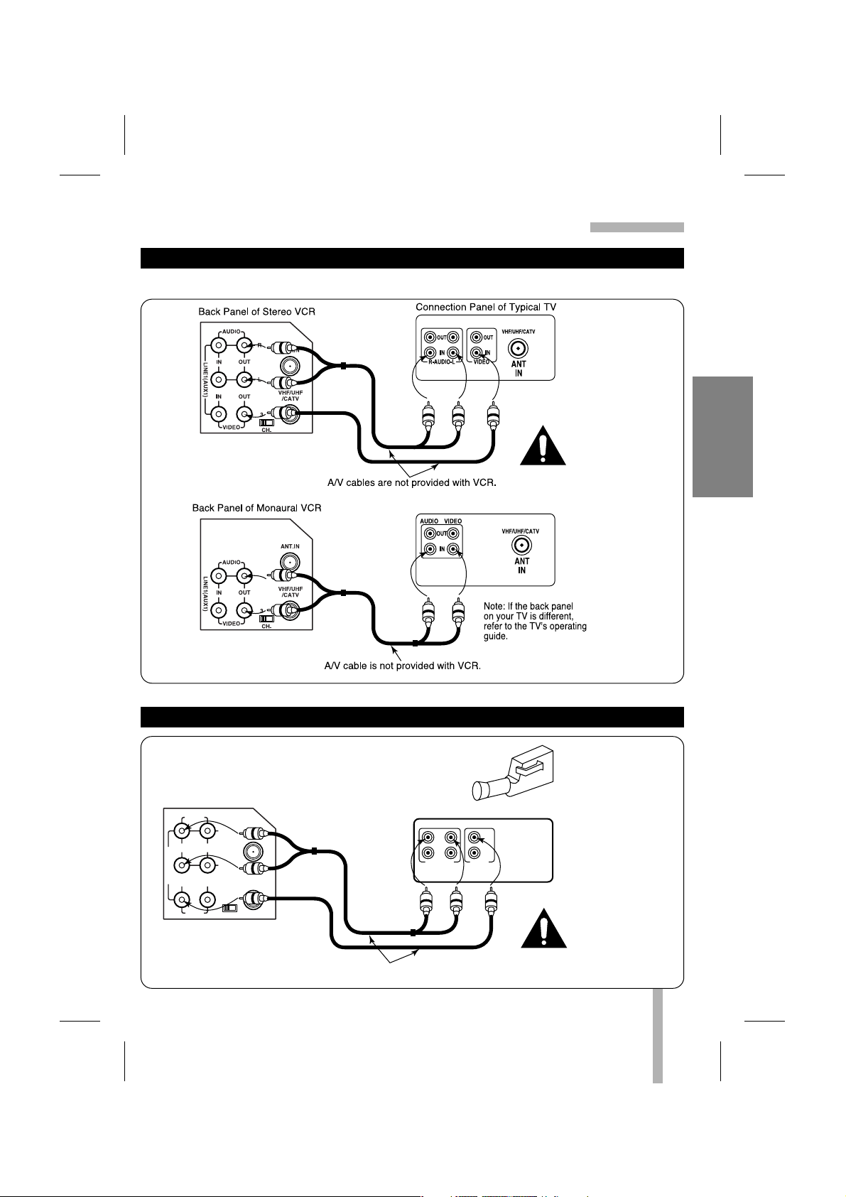
CONNECTIONS FOR YOUR VCR
6
Required connections for your VCR.
AUDIO
LINE1(AUX1)
R
L
IN
IN
OUT
OUT
ANT.IN
VIDEO
CH.
34
VHF/UHF
/CATV
Back Panel of Stereo VCR
Connection Panel of Typical TV
Antenna
Flat Wire
(300 ohm)
300/75 ohm
Adaptor
(Not provided)
Cable TV
Wall Jack
This cable is provided
with your VCR.
OR
OR
IN
OUT OUT
IN
R
L
AUDIO
VIDEO
VHF/UHF/CATV
ANT
IN
AUDIO
LINE1(AUX1)
R
L
IN
IN
OUT
OUT
ANT.IN
VIDEO
CH.
34
VHF/UHF
/CATV
Back Panel of
Typical Cable Box
CH3 CH4
CABLE
OUT IN
Back Panel of
Stereo VCR
Connection Panel of Typical TV
IN IN
OUTOUT
R
L
AUDIO VIDEO
VHF/UHF/CATV
ANT
IN
Cable TV
Wall Jack
This cable
is provided
with your VCR.
Turn off power or unplug VCR
before making any connections.
Turn off power or unplug
VCR before making any
connections.
CONNECTIONS WITHOUT A CABLE BOX
CONNECTIONS WITH A CABLE BOX
VCR SETUP
Page 7
7
VCR SETUP
CONNECTIONS FOR YOUR VCR (Cont’d)
Use A/V connections for a better picture.
Connection Panel of Typical Monaural TV
AUDIO
LINE1(AUX1)
R
L
IN
IN
OUT
OUT
ANT.IN
VIDEO
CH.
34
VHF/UHF
/CATV
Back Panel of Stereo VCR
OUT
IN
OUT
IN
R-AUDIO-L VIDEO
Jack panel of Accessory
A/V cables are not provided with VCR.
AUDIO/VIDEO (A/V) CONNECTIONS TO TV
CONNECTIONS WITHOUT A CABLE BOX
Turn off power
or unplug VCR
before making
any connections.
Turn off power
or unplug VCR
before making
any connections.
Accessory
Component:
Another VCR,
Camcorder,
Video Camera,
Satellite Receiver,
Laser Disc Player
Page 8
8
VCR SETUP
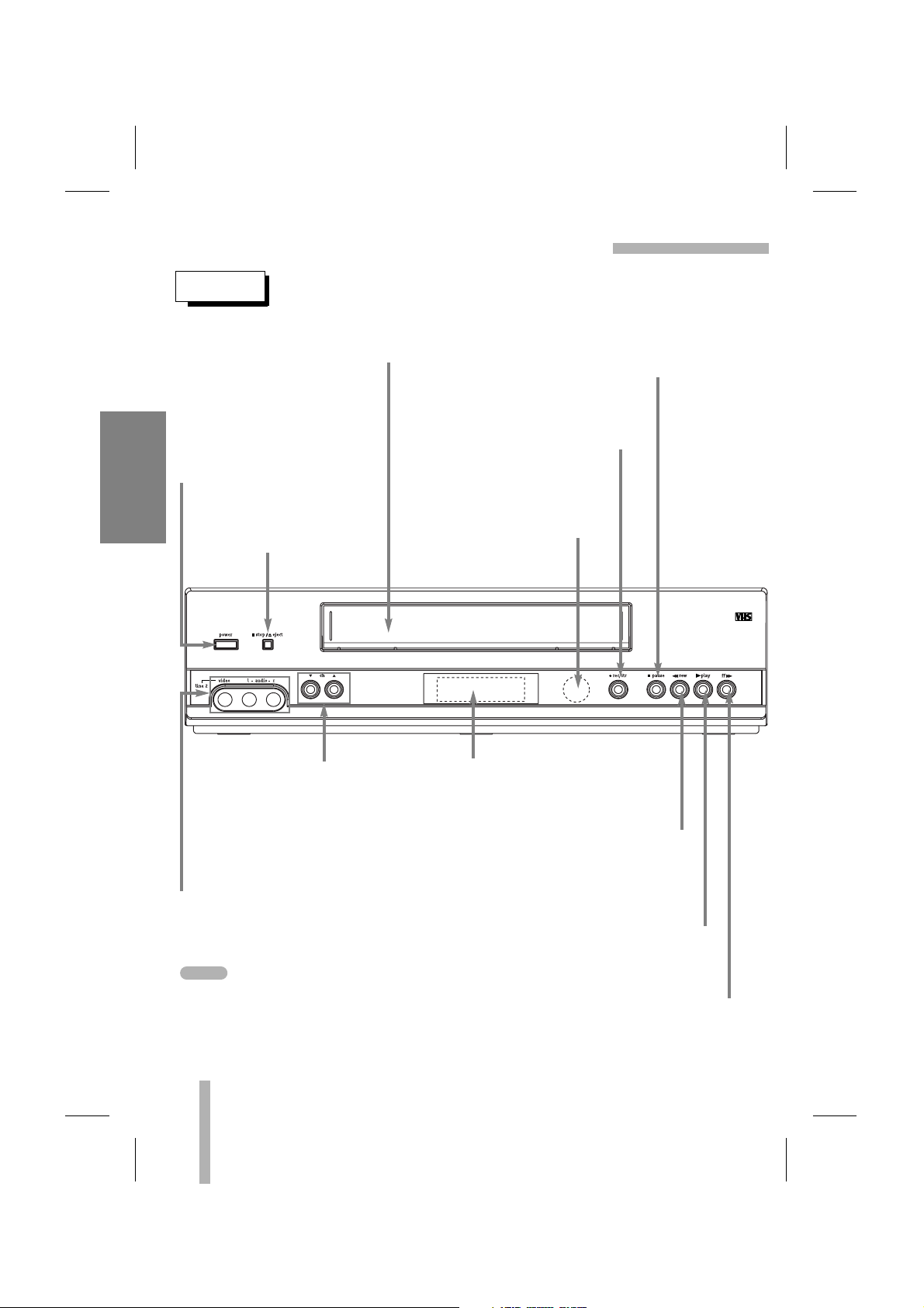
CONTROL NAMES AND LOCATIONS
FRONT
POWER
To turn the VCR on and off.
While plugged into an AC
outlet, the VCR consumes
2W of electrical power in
OFF condition.
CASSETTE COMPARTMENT
Where the video cassette is inserted.
STOP/EJECT
To stop the tape.
To eject the tape in the VCR.
PLAY
To play back a recorded tape
(page 21).
REW (Rewind)
To rewind the tape during the STOP
mode or for fast reverse picture
search (page 23).
INFRARED REMOTE SENSOR
Receives the signal from the
infrared remote control.
CHANNEL (DD/EE)
To scan up or down through
memorized channels (page 16)
or to manually adjust the tape’s
picture onscreen (page 21).
VCR Function Indicator Panel
Details are on the next page.
REC/ITR
To record normally (page 25) or to
activate Instant Timer Recording
(page 29).
PAUSE
To put playback on still (page 23) or
to pause recording (page 25).
FF (Fast Forward)
To advance the tape during the STOP mode
or for fast forward picture search (page 23).
VIDEO IN/AUDIO IN (L/R) JACKS (LINE2)
Connect the audio/video output cable from
an external unit (Audio system, TV/Monitor,
Another VCR) to these jacks.
Use INPUT on remote to select an A/V input
channels (LINE1 or LINE2).
NOTE
Page 9
9
VCR SETUP
CONTROL NAMES AND LOCATIONS (Cont’d)
INDICATOR PANEL
Cassette indicator
Lights while a cassette is
inserted, and flashes while
ejecting a cassette.
Record indicator
VCR indicator
Use TV/VCR on the remote control
to turn this indicator ON or OFF.
ON: for playback, VCR programming
or watching TV programs through the
VCR tuner
OFF: for watching TV programs
through TV tuner
REC
VCR
TIMER
AM
Clock/Tape operation indicator
HI — VCR turned on.
BYE — VCR turned off.
TIMER indicator
AM indicator
(PM is not displayed)
Front Panel Display shows which VCR
function you are using. For example, when
you press SP/SLP, SP or SLP appears
to indicate the tape speed. As you change
channels, the channel numbers appear. The
current time shows even while the VCR is
off.
Playback Messages
FF (Fast Forward) — Tape is advancing
rapidly.
CUE — Tape is advancing rapidly in
playback mode for visual search.
REV — Tape is reversing rapidly in playback
mode for visual search.
PLAY — Tape is playing at normal playback
speed.
REW (Rewind) — Tape is rewinding rapidly.
SLW — Tape is playing at slow-motion
speed.
STILL — Playback is paused on one frame.
STOP — Tape rewind or playback has
stopped.
Record Messages
RECP — Recording is paused.
SP or SLP — Displays the recording speed.
REC — VCR is recording.
STOP — Recording has stopped.
Tuner Messages
L1 or L2 — Auxiliary channel is selected for
viewing equipment connected to Audio/Video
jacks on front or rear of the VCR.
Ch _ — VCR is tuned to Channel _.
HI — VCR turned on.
BYE — VCR turned off.
Page 10
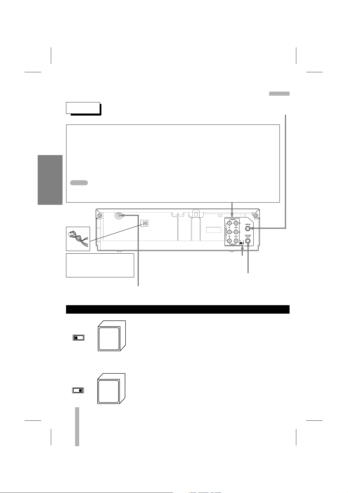
CONTROL NAMES AND LOCATIONS (Cont’d)
REAR
ANTENNA INPUT CONNECTOR
Connect the VHF/UHF/CATV antenna to this terminal.
AUDIO OUT (L/R) JACKS; Connect these output jacks to the audio input on an external
unit (Audio System, TV/Monitor, Another VCR).
VIDEO OUT JACK; Connect this output jack to the video input terminal on an external unit
(TV/Monitor, Another VCR).
AUDIO IN (L/R) JACKS; Connect the audio output cable(s) from an external unit (Audio
system, TV/Monitor, Another VCR) to these jacks.
VIDEO IN JACK; Connect the video output cable from an external unit (TV/Monitor,
Another VCR) to this jack.
Use INPUT to select an A/V input channel (LINE1 or LINE2).
POWER CORD
Connect only to an AC 120V, 60Hz outlet.
VCR OUTPUT CHANNEL SELECT SWITCH
Set this switch to channel 3 or 4.
VHF/UHF/CATV ANTENNA OUTPUT CONNECTOR
Connect this terminal to the VHF or UHF
antenna terminals on the back of a TV.
WARNING : Do not drop the
power cord tying band into the
unit. Doing so might cause a fire
or an electrical shock.
10
VCR SETUP
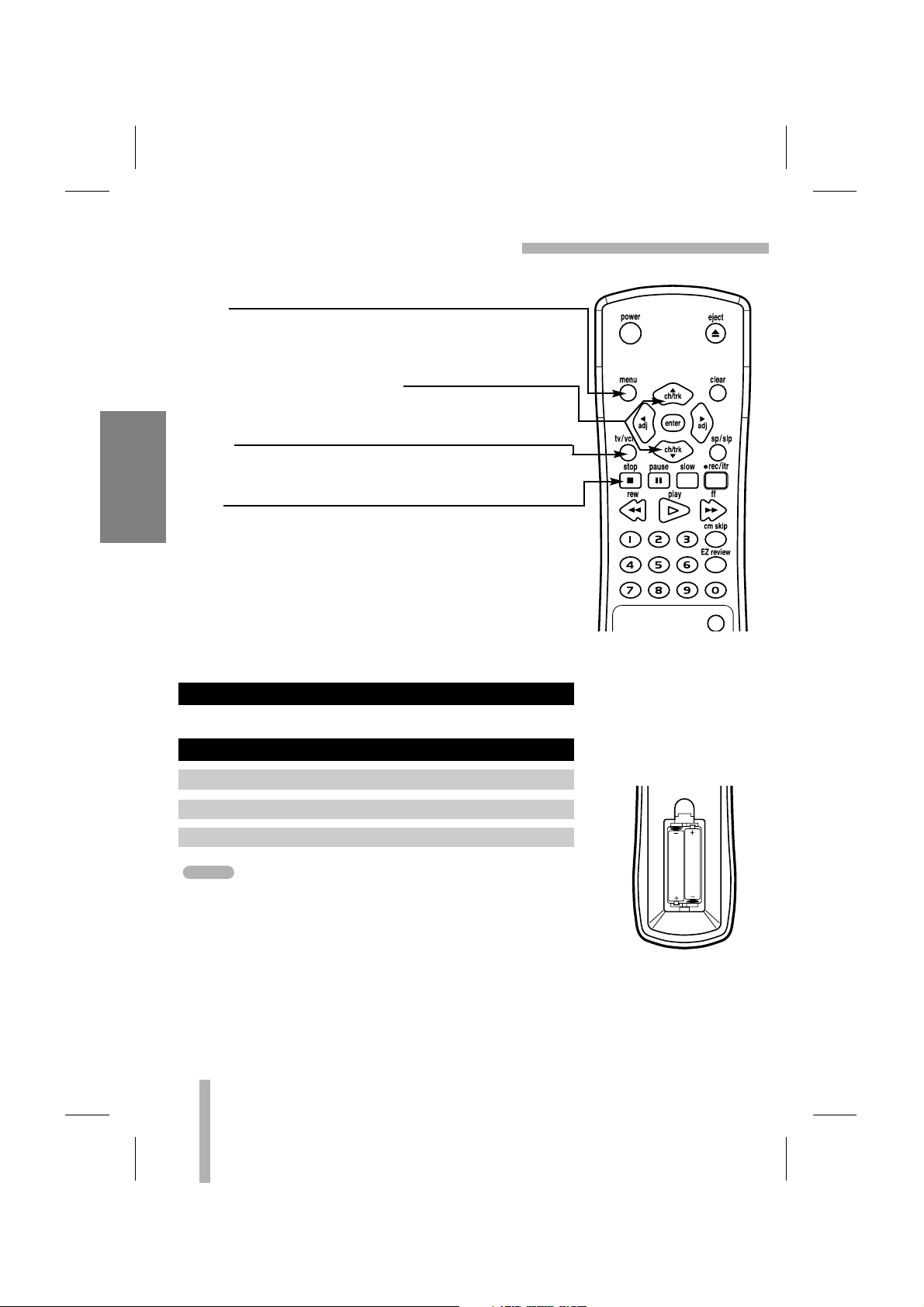
The CH3/CH4 switch on the VCR’s back panel determines
which channel the VCR uses to send video signals to your TV.
The TV must be tuned to the same channel you set with the
CH3/CH4 switch to see tape playback and status displays from
the VCR. To determine which video channel provides the best
picture for your system, try the switch in CH3 position and tune
your TV to channel 3; then try the CH4 position and tune your
TV to channel 4.
For a test display, press TV/VCR on remote repeatedly until
the VCR indicator light appears in the VCR’s front panel
display. Press MENU on the remote to see the main menu.
SET POSITION OF THE CH3/CH4 SWITCH
Tune
TV to
Ch.3
Tune
TV to
Ch.4
OR
CH.
34
CH.
34
NOTE
Page 11
11
VCR SETUP
REMOTE CONTROL
EJECT
To eject the tape in the VCR (page 18).
CLEAR
Cancels a timer recording (page 28).
Resets tape counter to 0:00:00 (page 34).
DD EE FF GG
ARROWS
Move up, down, left, right one row, column, or selection
(hold to repeat) (pages 14, 15).
ENTER
Accesses the onscreen menu (page 14).
Displays functions on the TV screen. Switches among
the clock, tape counter and tape remaining modes on
the display (pages 13, 34).
SP/SLP
Use to select recording speed (page 25).
SLOW
For slow motion playback (page 24).
CM SKIP
To fast forward picture search through 30 seconds of
recording (page 24).
EZ REVIEW
Replays the specified segment twice.
INPUT
Select the VCR’s line input or tuner.
NUMBER buttons
Use these buttons, numbered 0-9, to select a channel.
The remote control is used for most of the operations and features of the VCR. Before
proceeding, put batteries in the remote and become familiar with the buttons. Use only type
AAA batteries. The maximum operating distance is about 25 feet.
The POWER, PLAY, PAUSE, FF, REW and REC/ITR buttons on the remote control unit
perform the same functions as the corresponding buttons on the VCR. The following buttons
are on the remote control unit only.
input
Page 12
input
MENU
Displays the programming menu on the TV screen.
Quits the current screen or Pop-up, or returns to the
currently tuned channel (pages 14, 16).
CH/TRK (channel/tracking) (
DD/EE
)
•To scan up or down through memorized channels (page 16).
•To manually adjust the tape’s picture onscreen (page 21).
TV/VCR
To view channels selected by the VCR tuner or by the TV
tuner (pages 10, 25).
STOP
To stop playback or recording (pages 21, 25).
12
VCR SETUP
REMOTE CONTROL (Cont’d)
Aim the remote control at the sensor on the front panel of the VCR.
• The remote control will not operate properly if something
comes between the VCR and the remote control.
• If the effective range is short, try new batteries.
• An object between the VCR and remote control may block the
invisible light beam and operation will be impossible.
• Batteries installed with incorrect polarity may leak and damage
your Remote Control.
• Do not mix old and new batteries or carbon types with alkaline
types.
• Remove the batteries from the battery compartment if the
remote control will not be used for a long time.
HOW TO INSTALL THE BATTERIES
REMOTE CONTROL OPERATION
AAA
AAA
1.
Remove the battery compartment cover.
2. Insert 2 “AAA”-size batteries, match “+” and “-”.
3. Replace the cover.
NOTES
Page 13
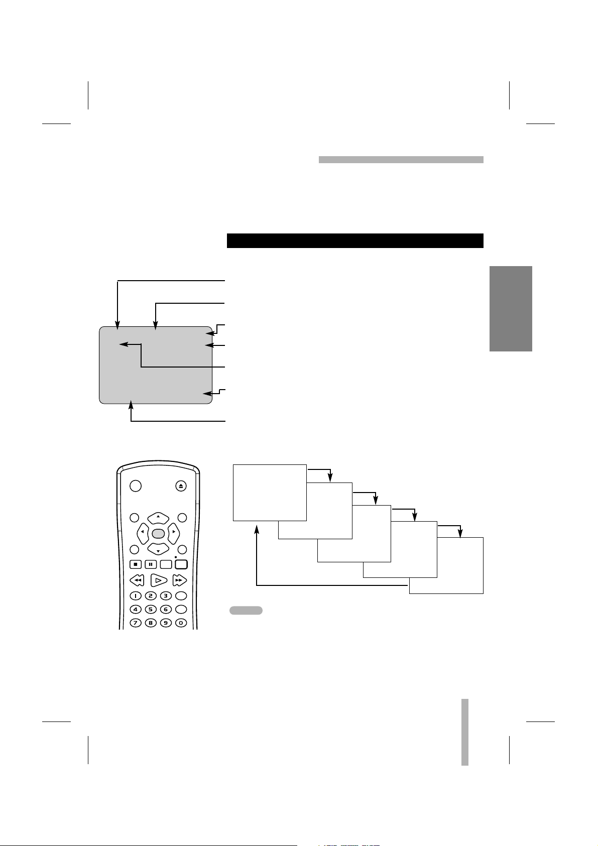
13
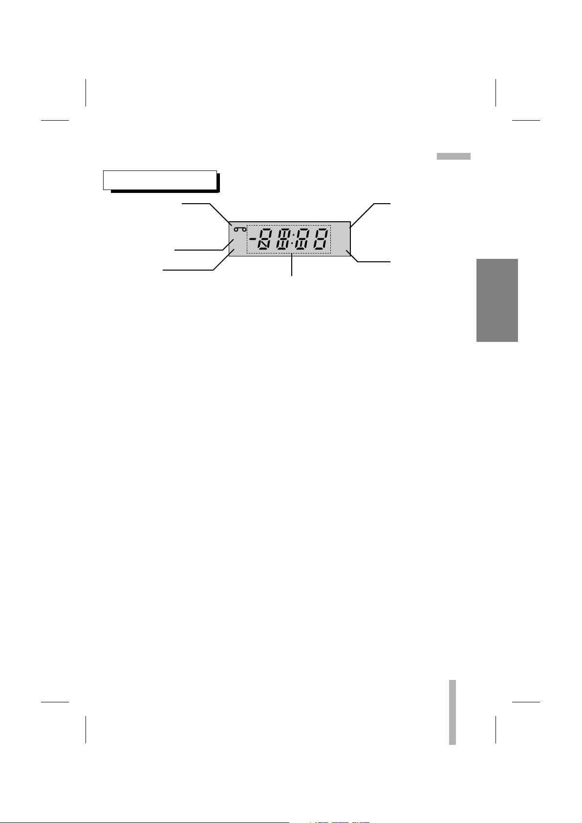
VCR SETUP
ONSCREEN DISPLAY (OSD)
REM 1:58
PREPARATION
• Turn on the power of both the VCR and TV.
• Tune the TV to the VCR output channel (CH 3 or 4).
• If a direct VIDEO/AUDIO connection is made between the
VCR and the TV, set the TV’s source selector to VIDEO.
Some of these functions will be displayed every time the VCR is
operated.
ONSCREEN FUNCTION DISPLAYS
0:35:40
2:15 PM
STOP CH 4
SP STEREO
JUL 5 , SAT 2:15 PM
• The function displays can be seen displayed on the TV screen
for 5 seconds.
• The clock (or tape counter, tape remaining) mode will remain
on the screen until you press ENTER.
• The tape counter and the remaining tape length indicator
appear only when a cassette is inserted. Also, the remaining
tape length indicator appears after any tape operation.
PLAY HI-FI CH 4
SP STEREO
JUL 5 , SAT 2:15 PM
FUNCTION DISPLAY
Indicates the function in progress.
HI-FI DISPLAY
Indicates the unit is playing back a tape recorded in HI-FI.
CHANNEL DISPLAY
Indicates the selected channel (or LINE1, LINE2).
STEREO/SAP DISPLAY (MONO is not displayed)
Shows the type of audio signal received by the VCR tuner.
TAPE SPEED DISPLAY
Shows the current tape speed.
CLOCK/COUNT/REMAIN DISPLAY
Shows the current time, the tape counter, and remaining time
on the tape.
DATE DISPLAY
Shows the current date. (Month/Date/Day of the week format)
Each press of the ENTER changes the TV screen in the
following sequence.
power
eject
menu clear
ch/trk
enter
adj
stop
rew play ff
ch/trk
pause slow
adj
sp / slptv / vcr
rec / itr
cm skip
EZ review
NOTES
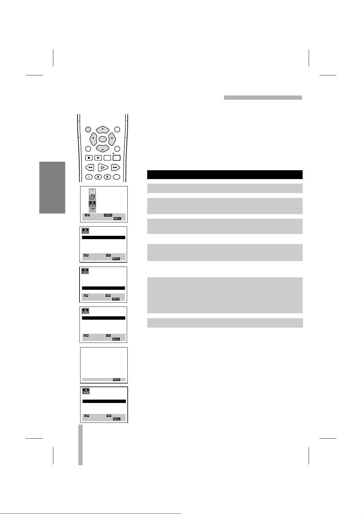
Page 14

14
VCR SETUP
SETTING THE ONSCREEN MENUS
The SETUP, clock setting (Clock Set), and timer recordings
(Program) features are conveniently accessible using the
onscreen menus. The following pages describe the Main and
sub menus.
PREPARATION
• Turn on the power of both the VCR and TV.
• Tune the TV to the VCR output channel (CH 3 or 4).
• If a direct VIDEO/AUDIO connection is made between the
VCR and the TV, set the TV’s source selector to VIDEO.
Use the remote control to adjust the VCR’s features.
CLOCK SET (pages 19-20)
PROGRAM (pages 26-28)
TUNING (pages 16-17)
SETUP (page 15)
MENU SELECTION
MAIN MENU
MONTH: JANUARY
DAY : 1 WED
YEAR : 2003
TIME : 12 : 00 AM
SELECT
TO EXIT PRESS
ADJUST
AUTO CLOCK SET : ON
DAYLIGHT SAVING:AUTO
TIME ZONE: AUTO
CLOCK
PROGRAM
TUNING
SETUP
SELECT
TO EXIT PRESS
ENTER
SELECT
TO EXIT PRESS
ADJUST
PROGRAM 1
MONTH :
DAY :
START :
STOP :
CHANNEL:
SPEED :
REPEAT :
AUTO CHANNEL SET
TUNING BAND: TV
CH. ADD/DEL: CH. 2 ADD
SOURCE SELECT: TUNER
SELECT
TO EXIT PRESS
ADJUST
FUNCTION OSD : ON
LANGUAGE SELECT:ENGLISH
AUDIO MODE: HI-FI
BROADCAST TYPE: STEREO
AUDIO OUTPUT: STEREO
SELECT
TO EXIT PRESS
ADJUST
1. Press MENU and the MAIN menu will appear.
2. Select the desired menu with the
DD
or EEbutton and then
press ENTER.
eject
power
menu clear
sp / slptv / vcr
stop
rew play ff
cm skip
EZ review
pause slow
rec / itr
ch/trk
adj
enter
ch/trk
adj
input
• Menus remain on the screen for 3 minutes.
NOTE
Page 15

15
VCR SETUP
SETUP MENU FEATURES AND OPERATION
SETUP MENU
Use DDor EEto choose a
desired option on the
SETUP menu. Then use
FF
or GGto choose a
desired setting.
The onscreen display of this VCR can be turned on or off.
The onscreen programming menus of this VCR can be displayed
in either English, Spanish, or French.
The VCR has two separate audio playback systems, the high quality
VHS Hi-Fi system and standard NORMAL mono system. The same
audio is generally recorded on both systems. The VHS Hi-Fi system
plays on separate (left and right) channels, and the NORMAL system
plays monaural sound. The normal track is always played so the
cassette can be played on a VCR that does not have VHS Hi-Fi.
Multichannel Television Sound (MTS) carries stereo and/or
Second Audio Program (SAP) bilingual signals. Set this display
to the desired position when both MTS stereo and SAP signals
are received. When only one of the MTS signal is received, the
VCR automatically selects the corresponding receiving mode
(Stereo or SAP) regardless of the selected position.
For normal operation, the display should be in the STEREO position. The VCR will then record a STEREO program when available,
and record a mono program if the program is NOT IN STEREO.
• For weak STEREO and/or SAP broadcasts, changing the dis-
play to mono may give clearer sound.
Used during playback [when AUDIO MODE display (HI-FI/NORMAL) is in HI-FI position] for selecting the audio output signals from
the AUDIO OUT terminals (L ch and R ch), and VHF/UHF/CATV.
This display setting should normally be left in the stereo position,
so that when a stereo tape is played, the stereo sound will be
heard through the left and right channels. If a mono tape is
played and the audio output is set to stereo, the same mono
sound will be heard from both left and right channels.
AUDIO OUTPUT DISPLAY (STEREO/LEFT/RIGHT)
BROADCAST TYPE DISPLAY (STEREO/SAP/MONO)
AUDIO MODE DISPLAY
LANGUAGE SELECT
FUNCTION OSD
Go to the AUDIO MODE option and select HI-FI or NORMAL
using
FF
or GG.
Go to the BROADCAST TYPE option and select STEREO,
SAP, or MONO using
FF
or GG.
Go to the AUDIO OUTPUT option and select STEREO, LEFT,
or RIGHT using
FF
or GG.
Go to the LANGUAGE SELECT option and select ENGLISH,
SPANISH, or FRENCH using
FF
or GG.
Set up the FUNCTION OSD option by selecting ON or OFF
using
FF
or GG.
MAIN MENU
CLOCK
PROGRAM
TUNING
SETUP
SELECT
TO EXIT PRESS
ENTER
FUNCTION OSD : ON
LANGUAGE SELECT:ENGLISH
AUDIO MODE: HI-FI
BROADCAST TYPE: STEREO
AUDIO OUTPUT: STEREO
SELECT
TO EXIT PRESS
ADJUST
Page 16
16
VCR SETUP
CHANNEL/SOURCE SELECTION
This VCR is equipped with a frequency synthesized tuner capable of receiving up to 181 channels. These include VHF channels 2-13, UHF channels 14-69 and CATV channels 1-125.
PREPARATION
• Connect the VCR to the desired type of antenna or cable TV
system, as shown in ANTENNA TO VCR CONNECTIONS and
CABLE ANTENNA (CATV) CONNECTION (page 6).
• Switch on the power to the VCR and TV.
• Tune the TV to the VCR output channel (CH 3 or 4).
Press
FF
or GGrepeatedly to select TUNER, LINE1 or LINE2.
The VCR will automatically search for all available active channels in the area and place them in the tuner’s memory.
Use CH/TRK (
DD/EE
) or CH (▲/▼) on the front panel to cycle
through the channels in the VCR’s memory.
AUTO CHANNEL PROGRAMMING
1. Press MENU and the MAIN menu will appear.
2. Use
DD
or EEto select the TUNING menu option, then press
ENTER. The TUNING menu will appear.
3. Use
EE
to choose the SOURCE SELECT option, then Use
FF
or GGto select TUNER.
4. Use
DD
or EEto choose the AUTO CHANNEL SET option,
then press
FF
or GGto start the channel search.
5. Select the TUNING BAND: TV or CATV.
TV is for over the air antenna reception.
CATV is for cable or wireless cable subscribers.
Use
DD
or EEto choose the TUNING BAND option, then use
FF
or GGto select TV or CATV.
6. Press MENU to return to the TV screen.
menu clear
sp / slptv / vcr
stop
rew play ff
cm skip
EZ review
pause slow
rec / itr
ch/trk
adj
enter
ch/trk
adj
SELECT
TO EXIT PRESS
AUTO CHANNEL SET
TUNING BAND: TV
CH. ADD/DEL: CH. 2 ADD
SOURCE SELECT: TUNER
SELECT
TO EXIT PRESS
AUTO CHANNEL SET
TUNING BAND: TV
CH. ADD/DEL: CH. 2 ADD
SOURCE SELECT: TUNER
SELECT
TO EXIT PRESS
AUTO CHANNEL SET
TUNING BAND: TV
CH. ADD/DEL: CH. 2 ADD
SOURCE SELECT: TUNER
SELECT
TO EXIT PRESS
AUTO CHANNEL SET
PROCEEDING
CHANNEL 13
CLOCK
PROGRAM
TUNING
SETUP
ADJUST
ADJUST
ADJUST
ENTER
TO EXIT PRESS
AUTO CHANNEL SET
TUNING BAND: TV
CH. ADD/DEL: CH. 2 ADD
SOURCE SELECT: TUNER
SELECT
TO EXIT PRESS
ADJUST
Page 17

17
VCR SETUP
CHANNEL SELECTION (Cont’d)
You don’t need to disconnect the VCR from the TV to watch TV
separately. When the VCR’s power is OFF, or when the VCR’s
power is ON and the TV/VCR selector is set to TV, the TV will
operate as if it were connected directly to the antenna or cable.
• The power cord must be plugged into an AC outlet.
• To view or record cable TV programs with the VCR, the VCR’s
TUNING BAND option must be set to CATV (TUNING menu).
• Do not place the VCR directly on top of the TV. This may
cause interference in the picture and sound (of the VCR) during the recording or playback mode. If this interference
occurs, move the VCR away from the TV.
Turn on the TV and tune it to the
channel that you wish to watch.
Set POWER to OFF.
This feature allows you to add or erase channels from memory
manually.
Repeat steps 3 and 4 to add or erase channels.
TO ADD OR ERASE CHANNELS FROM MEMORY
VIEWING TV ONLY
MAIN MENU
TUNING MENU
1. Press MENU and the MAIN menu will appear.
2. Use
DD
or EEto select the TUNING menu option, then press
ENTER. The TUNING menu will appear.
3. Use
EE
to choose the CH. ADD/DEL option. UseFFor GGto
select a channel to add or erase.
4. Use ENTER to add or erase the channel.
5. Press MENU to return to the TV screen.
CLOCK
PROGRAM
TUNING
SETUP
SELECT
TO EXIT PRESS
ENTER
AUTO CHANNEL SET
TUNING BAND: TV
CH. ADD/DEL: CH. 2 ADD
SOURCE SELECT: TUNER
ADD/DELETE
SELECT
TO EXIT PRESS
ADJUST
NOTES
Page 18

18
VCR SETUP
VIDEO CASSETTE TAPES
This VCR will operate with any video cassette which has
the mark. The table below shows the recording/playback
time of VHS cassettes when they are used in the SP, LP and
SLP speeds. (LP speed is for playback only.)
• Do not expose video cassettes to extreme heat, high
humidity, or strong magnetic fields.
• Do not tamper with the cassette mechanism.
• Do not touch the tape with your fingers.
• Always store an unused cassette in its case.
Hold the cassette with the arrow side up (top). Insert the
cassette gently into the slot in the direction of the arrow (on the
cassette) until the loading mechanism automatically pulls the
cassette into the unit. Make certain that the cassette is inserted
correctly.
• If the cassette is not loaded correctly, the VCR will eject the
cassette automatically after approximately 3 seconds.
Press STOP/EJECT twice or press EJECT on the remote
control. The cassette will be ejected automatically. After the
cassette is visible in the tape slot, pull it out to remove it.
• Unloading the cassette is possible only when the power cord
is connected to the wall outlet.
• The cassette can be ejected when STOP/EJECT is pressed,
even if the VCR’s power is OFF.
UNLOADING
LOADING
WHEN HANDLING VIDEO CASSETTES
TYPE
T-60 T-120 T-160
SPEED
SP MODE 60 mins. 120 mins. 160 mins.
LP MODE 120 mins. 240 mins. 320 mins.
SLP MODE 180 mins. 360 mins. 480 mins.
To prevent accidental erasure, remove the tab after
recording.
To record again cover the
hole with vinyl tape.
SAFETY TAB
Page 19

19
VCR SETUP
SETTING THE CLOCK
menu clear
sp / slptv / vcr
stop
rew play ff
cm skip
EZ review
pause slow
rec / itr
ch/trk
adj
enter
ch/trk
adj
PREPARATION
• Turn on the power of both the VCR and TV.
• Tune the TV to the VCR output channel (CH 3 or 4).
• If a direct VIDEO/AUDIO connection is made between the
VCR and the TV, set the TV’s source selector to VIDEO.
The VCR gives you two ways to set the time and date: the Auto
Clock Feature or manually. The Auto Clock Feature enables the
VCR to set up the clock when the VCR is turned off.
The Auto Clock Set feature is set to ON at the factory. In the ON
setting, the VCR looks for a channel carrying XDS (Extended
Data Services) information. XDS updates the clock using the
Coordinated Universal Time.
If you choose AUTO, the VCR sets the clock using the DST
information broadcast in the signal (channel).
If you choose ON, the VCR sets the clock when the Daylight
Saving Time is started and ended.
If “AUTO” is selected as the time zone, the VCR sets the clock
using the first Coordinated Universal Time information it finds in
a broadcast signal.
AUTO CLOCK SET
• The clock uses the 12-hour system. (Be sure to set AM and
PM correctly.)
• The buttons for setting the clock are on the remote control.
• An illogical date will not be accepted (for example:
February 30).
• The initial Clock Setting is JANUARY 1, 2003, 12:00 AM.
MAIN MENU
CLOCK MENU
CLOCK
PROGRAM
TUNING
SETUP
SELECT
TO EXIT PRESS
ENTER
1. Press MENU and the MAIN menu will appear.
2. Use
DD
or EEto choose the CLOCK menu option.
Press ENTER and the CLOCK menu will appear.
3. Use
EE
to choose the AUTO CLOCK SET option.
Use
FF
or GGto choose ON.
6. Press MENU when finished.
7. Turn off the VCR to complete auto clock setting.
Things to know before starting
There are cases that the
TV station does not send
or sends wrong date
and/or time information
and the VCR sets the time
incorrectly.
In this case we recommend that you set the
clock manually.
4. Use
EE
to choose the DAYLIGHT SAVING option.
Use
FF
or GGto choose AUTO, ON or OFF.
5. Use
EE
to choose the TIME ZONE option.
UseFFor GGto choose the correct time zone (AUTO,
EASTERN, CENTRAL, MOUNTAIN, PACIFIC, ALASKA, or
HAWAII).
MONTH: JANUARY
DAY : 1 WED
YEAR : 2003
TIME : 12 : 00 AM
AUTO CLOCK SET : ON
DAYLIGHT SAVING:AUTO
TIME ZONE: AUTO
SELECT
TO EXIT PRESS
MONTH: JANUARY
DAY : 1 WED
YEAR : 2003
TIME : 12 : 00 AM
AUTO CLOCK SET : ON
DAYLIGHT SAVING:AUTO
TIME ZONE: AUTO
SELECT
TO EXIT PRESS
MONTH: JANUARY
DAY : 1 WED
YEAR : 2003
TIME : 12 : 00 AM
AUTO CLOCK SET : ON
DAYLIGHT SAVING:AUTO
TIME ZONE: AUTO
SELECT
TO EXIT PRESS
ADJUST
ADJUST
ADJUST
NOTE
Page 20

20
VCR SETUP
SETTING THE CLOCK (Cont’d)
CLOCK MENU
Example: JULY 5, 2003 ; 2:15 AM
The day of the week will display automatically.
“AUTO CLOCK SET” must be set to “OFF”. If set to “ON”, an
incorrect date and/or time will be entered again when the VCR
is turned off.
MANUAL CLOCK SET
MONTH: JANUARY
DAY : 1 WED
YEAR : 2003
TIME : 12 : 00 AM
SELECT
TO EXIT PRESS
ADJUST
AUTO CLOCK SET : ON
DAYLIGHT SAVING:AUTO
TIME ZONE: AUTO
1. Press MENU and the MAIN menu will appear.
2. Use
DD
or EEto choose the CLOCK menu.
Press ENTER and the CLOCK menu will appear.
3. Use
FF
or GGto choose the month.
4. Use
EE
to choose the DAY option.
Use
FF
or GGto choose the day.
5. Use
EE
to choose the YEAR option.
Use
FF
or GGto choose the year.
6. Use
EE
to choose the TIME option.
Use
FF
or GGto choose the time.
7. Use
EE
to choose the DAYLIGHT SAVING option.
Use
FF
or GGto choose the ON or OFF option.
8. Press MENU when finished.
MAIN MENU
CLOCK
PROGRAM
TUNING
SETUP
SELECT
TO EXIT PRESS
ENTER
MONTH: JULY
DAY : 5 SAT
YEAR : 2003
TIME : 12 : 00 AM
AUTO CLOCK SET : OFF
DAYLIGHT SAVING:AUTO
TIME ZONE: AUTO
SELECT
TO EXIT PRESS
MONTH: JULY
DAY : 5 SAT
YEAR : 2003
TIME : 12 : 00 AM
AUTO CLOCK SET : OFF
DAYLIGHT SAVING:AUTO
TIME ZONE: AUTO
SELECT
TO EXIT PRESS
MONTH: JULY
DAY : 5 SAT
YEAR : 2003
TIME : 2 : 15 AM
AUTO CLOCK SET : OFF
DAYLIGHT SAVING:AUTO
TIME ZONE: AUTO
SELECT
TO EXIT PRESS
MONTH: JULY
DAY : 5 SAT
YEAR : 2003
TIME : 2 : 15 AM
AUTO CLOCK SET : OFF
DAYLIGHT SAVING: ON
TIME ZONE: AUTO
SELECT
TO EXIT PRESS
ADJUST
ADJUST
ADJUST
ADJUST
NOTE
Page 21

NORMAL PLAYBACK
21
PLAYBACK
PREPARATION
• Turn on the TV.
• Tune the TV to the VCR output channel (CH 3 or 4).
• If a direct VIDEO/AUDIO connection is made between the
VCR and the TV, set the TV’s source selector to VIDEO.
The indicator will light and the VCR will power-up
automatically.
• Make sure that the TIMER indicator in the VCR indicator panel
is not lighted. If it is, press POWER once.
• If a tape without a safety tab is inserted, the VCR will start
playback automatically.
PLAY appears in the VCR indicator panel and TV screen.
• It is not necessary to select the tape speed for playback. It will
be automatically selected by the VCR.
• In playback, the TV/VCR selector switches to VCR mode
automatically.
STOP appears in the VCR indicator panel and on the TV screen.
• If the tape reaches the end before STOP is pressed, the VCR
will automatically stop, rewind, eject, and it will turn itself off.
AUTO TRACKING
The automatic tracking function adjusts the picture to remove
snow or streaks.
The AUTO TRACKING function works in the following cases:
• A tape is played back for the first time.
• Tape speed (SP, LP, SLP) changes.
• Streaks or snow appear because of scratches on the tape.
MANUAL TRACKING
If noise appears on the screen during playback, press either
CH/TRK (
DD/EE
) on the remote control or CH (DD/EE) on the front
panel until the noise on the screen is reduced.
• In case of vertical jitter, adjust these controls very carefully.
• Tracking is automatically reset to normal when the tape is
ejected or the power cord is unplugged for more than 3
seconds.
TRACKING CONTROL
NORMAL PLAYBACK
1. Insert a prerecorded video cassette.
2. Press PLAY once.
3. Press STOP to stop playback.
eject
power
menu clear
sp / slptv / vcr
stop
rew play ff
cm skip
EZ review
pause slow
rec / itr
ch/trk
adj
enter
ch/trk
adj
input
Page 22

22
PLAYBACK
NORMAL PLAYBACK (Cont’d)
This VCR features full automatic playback and rewind.
Load a cassette (with the safety tab removed).
• The power turns on automatically and playback begins.
• At the end of the tape, the VCR stops, then rewinds.
• The cassette is ejected after rewinding and the VCR turns itself off automatically.
This feature is especially helpful when you finish watching a tape. Press STOP, REW, and
POWER. The VCR will rewind the tape and turn itself off automatically.
1. Press STOP when you finish watching a tape.
2. Press REW to rewind the tape.
3. Press POWER during the REWIND mode, the VCR will enter the AUTO POWER SHUT-
OFF mode.
4. REW will flash on the VCR indicator panel.
5. After tape is rewound, VCR will turn off automatically.
AUTO POWER SHUT-OFF FUNCTION
AUTO PLAY SYSTEM
LOAD
TAPE
AUTO
REWIND
AUTO
POWER
OFF
AUTO
EJECT
AUTO
PLAY
power
rew
stop
REWIND
AUTO
POWER
OFF
Page 23

23
PLAYBACK
SPECIAL EFFECTS PLAYBACK
These special effects are available during playback.
During PLAYBACK mode...
Still picture will appear on the TV screen.
• If a still picture vibrates vertically, stabilize it by pressing
CH/TRK (DD/EE) on the remote control.
• If the VCR is left in the STILL mode for more than 5 minutes,
the VCR will automatically enter the STOP mode to
protect the tape and video heads.
This function lets you quickly and visually search for a desired
tape section in either direction: forward or reverse.
During PLAYBACK mode...
The VCR will be activated in the SEARCH mode and CUE or
REV will appear on the VCR indicator panel.
• If the VCR is left in the SEARCH mode for more than 3 minutes, the VCR will automatically enter the PLAY mode, to
protect the tape and video heads.
The VCR must be in the STOP Mode.
Visual search (Cue/Review) begins so you can check what is on
the tape.
• The CUE or REVIEW mode will continue until the FF or REW
button is released.
LOGIC SEARCH FUNCTION
VISUAL SEARCH FUNCTION
TO WATCH A STILL (or Frame Advance) PICTURE
1. Press PAUSE.
3. To continue normal playback, press PLAY.
1. Press desired search button (FF or REW).
2. To continue normal playback, press PLAY.
2. Press PAUSE repeatedly to advance the video picture one
frame at a time while viewing a still picture.
eject
power
menu clear
sp / slptv / vcr
stop
rew play ff
cm skip
EZ review
pause slow
rec / itr
ch/trk
adj
enter
ch/trk
adj
input
1. Press FF or REW once. Fast winding begins.
2. Press and hold FF or REW again.
3. When released, Fast Forward or Rewinding resumes.
Page 24

24
PLAYBACK
SPECIAL EFFECTS PLAYBACK (Cont’d)
eject
power
menu clear
sp / slptv / vcr
stop
rew play ff
cm skip
EZ review
pause slow
rec / itr
adj
enter
adj
ch/trk
ch/trk
input
SPECIAL EFFECTS PLAYBACK NOTES:
• Horizontal lines (noise bars) will appear on the TV screen.
This is normal.
• The audio is automatically muted during special effect
modes, so there is no sound during search.
• During the high-speed picture search modes, a short period is
needed to stabilize tape speed when re-entering the PLAY
mode. Slight interference may be observed during this period.
During PLAYBACK mode...
The tape will be played back at a speed 1/19 times slower than
the normal speed.
• During slow playback, CH/TRK (
DD/EE
) on the Remote Control
can be used to minimize noise bands.
• If slow mode continues for more than 3 minutes, the VCR will
automatically change to PLAYBACK mode.
This is useful for skipping commercials or short program
segments.
During PLAYBACK mode...
The tape will fast forward picture search through 30 seconds of
recording.
The skipping time can be extended by pressing CM SKIP.
Subsequent presses result in advancing the fast forward picture
search time by 30-second increments (maximum 3 minutes).
CM SKIP (Commercial Skip)
USING THE SLOW MOTION FEATURE
1. Press CM SKIP.
2. When the search is complete, the VCR will go into
PLAYBACK mode automatically.
1. Press SLOW.
2. Press PLAY to return to normal playback speed or press
STOP to stop tape movement.
Page 25

25
RECORDING
NORMAL RECORDING
PREPARATION
• Turn on the power of both the VCR and TV.
• Tune the TV to the VCR output channel (CH 3 or 4).
• If a direct VIDEO/AUDIO connection is made between the
VCR and the TV, set the TV’s source selector to VIDEO.
• If you are recording from an external source via audio/video
input jacks (at the Rear or Front panel), select LINE1 or LINE2
using the INPUT button.
• This VCR is not designed to record in LP mode.
Recording will start. (REC will appear)
• If a cassette with no safety tab is loaded, the cassette will be
ejected automatically.
• If the tape reaches the end before STOP is pressed, the VCR
will automatically stop, rewind, eject, and turn itself off.
During the RECORDING mode...
RECP will show on the VCR indicator panel.
• After 5 minutes in pause mode, the tape will be stopped
automatically to protect the tape and the video heads.
The VCR indicator disappears.
To record one TV program while watching another
To PAUSE the recording
1. Insert the video cassette with the safety tab in place.
2. Select the desired channel by using CH/TRK (▲/▼).
3. Set the desired speed (SP or SLP) using SP/SLP.
4. Set the MTS mode as desired (See page 15, 33).
5. Press REC/ITR once.
6. Press STOP to stop recording.
1. Press PAUSE to pause the tape.
2. When you want to continue recording, press PAUSE again
or press REC/ITR.
Always use PAUSE for
best results when making
changes during recording.
For example: To change
channels during recording,
first press PAUSE to put
the unit in pause mode.
Then select the desired
channel on the VCR, and
press PAUSE again to
resume recording.
1. Press TV/VCR to select the TV mode during recording.
2. Using the TV tuner, select the channel to be viewed.
eject
power
menu clear
sp / slptv / vcr
stop
rew play ff
cm skip
EZ review
pause slow
rec / itr
ch/trk
adj
enter
ch/trk
adj
input
Page 26

TIMER RECORDING
26
This VCR can be programmed to record up to 8 programs
within a period of 1 year. For unattended recording, the timer
needs to know the channels to be recorded and the starting and
ending times.
PREPARATION
• Turn on the power of both the VCR and the TV.
• Tune the TV to the VCR output channel (CH 3 or 4).
• Make sure the TUNING BAND in the TUNING menu is set
appropriately (TV or CATV) (see illustration left).
The PROGRAM menu will appear.
• If all programs have already been entered, FULLY
PROGRAMMED message will appear for a moment and then
PROGRAM 1 will appear on the TV screen.
Example JULY.
• If you try to set the program timer before setting the clock,
PLEASE SET THE CLOCK appears for a moment and then
CLOCK menu appears on the TV screen. Set the time and
date before proceeding.
• The display contents will be automatically replaced by TV
programs after 3 minutes.
• Make sure a tape is in the VCR and the safety tab is in place
or the tape will be automatically ejected.
MAIN MENU
TUNING MENU
1. Press MENU and the MAIN menu will appear.
2. Use
DD
or EEto choose the PROGRAM menu.
3. Press ENTER to go to the PROGRAM menu.
4. Use
FF
or GGto choose the PROGRAM No. (1-8).
5. Use
EE
to choose the MONTH option.
Use
FF
or GGto choose the desired month.
Things to know before starting
menu clear
sp / slptv / vcr
stop
rew play ff
cm skip
EZ review
pause slow
rec / itr
ch/trk
adj
enter
ch/trk
adj
RECORDING
AUTO CHANNEL SET
TUNING BAND: TV
CH. ADD/DEL: CH. 2 ADD
SOURCE SELECT: TUNER
SELECT
TO EXIT PRESS
SELECT
TO EXIT PRESS
PROGRAM 1
MONTH :
DAY :
START :
STOP :
CHANNEL:
SPEED :
REPEAT :
SELECT
TO EXIT PRESS
PROGRAM 1
MONTH : JULY
DAY :
START :
STOP :
CHANNEL:
SPEED :
REPEAT :
SELECT
TO EXIT PRESS
ADJUST
CLOCK
PROGRAM
TUNING
SETUP
ADJUST
ADJUST
ENTER
Page 27

27
RECORDING
TIMER RECORDING (Cont’d)
Example: 6 SUN
Example: 6:00 PM
Example: 7:30 PM
Example CH 4
Cable Users: If you have CABLE TV and used the Cable Box
setup on the Cable Connections (page 7) using a cable box converter, you must tune the VCR to the cable box output channel
(usually CH 3 or 4). Change channels with the cable box instead
of the VCR.
Example SP
• The AUTO mode determines how much tape is left and
switches speed from SP to SLP, if necessary, to complete
recording the program. There will be some picture and sound
distortion at the point of the speed change.
Example: ONCE
If the recording data is wrong, Use
DD
to select the data and
correct it using
FF
or GG.
ONCE event....for recording up to 8 programs on a single day
or over the days within a period of 1 year.
WEEKLY event....for recording up to 8 programs on a certain
day of every week.
DAILY event....for recording up to 8 programs at the same
time(s) Monday through Friday.
6. Use
EE
to choose the DAY option.
Use
FF
or GGto choose the desired day.
7. Use
EE
to choose the START option.
Use
FF
or GGto choose the desired start time.
8. Use
EE
to choose the STOP option.
Use
FF
or GGto choose the desired stop time.
9. Use
EE
to choose the CHANNEL option.
Use
FF
or GGto choose the desired channel (Channel XX,
LINE1 or LINE2).
10. Use
EE
to choose the SPEED option.
Use
FF
or GGto choose the desired tape speed (AUTO, SP,
or SLP).
11. Use
EE
to choose the REPEAT option.
Use
FF
or GGto choose the desired repeat (ONCE,
WEEKLY, or DAILY).
PROGRAM 1
MONTH : JULY
DAY : 6 SUN
START :
STOP :
CHANNEL:
SPEED :
REPEAT :
SELECT
TO EXIT PRESS
PROGRAM 1
MONTH : JULY
DAY : 6 SUN
START : 6:00 PM
STOP :
CHANNEL:
SPEED :
REPEAT :
SELECT
TO EXIT PRESS
PROGRAM 1
MONTH : JULY
DAY : 6 SUN
START : 6:00 PM
STOP : 7:30 PM
CHANNEL:
SPEED :
REPEAT :
SELECT
TO EXIT PRESS
PROGRAM 1
MONTH : JULY
DAY : 6 SUN
START : 6:00 PM
STOP : 7:30 PM
CHANNEL: 4 TV
SPEED : AUTO
REPEAT : ONCE
SELECT
TO EXIT PRESS
PROGRAM 1
MONTH : JULY
DAY : 6 SUN
START : 6:00 PM
STOP : 7:30 PM
CHANNEL: 4 TV
SPEED : SP
REPEAT : ONCE
SELECT
TO EXIT PRESS
PROGRAM 1
MONTH : JULY
DAY : 6 SUN
START : 6:00 PM
STOP : 7:30 PM
CHANNEL: 4 TV
SPEED : SP
REPEAT : ONCE
SELECT
TO EXIT PRESS
ADJUST
ADJUST
ADJUST
ADJUST
ADJUST
ADJUST
Page 28

28
RECORDING
TIMER RECORDING (Cont’d)
• If the program preset time is past, the PAST TIME PRO-
GRAMMED message will appear on the TV screen. Return to
the incorrect program and reprogram it with the correct time.
• If you had entered a past date, the timer recording will be per-
formed on that date of the next year.
• Additional programs may be entered by repeating steps 1-12.
Cable Users: If your cable hookup is via a TV converter box, you
can program multiple recordings only on the converter box output channel. This is because the converter determines what
channel you view through your VCR.
You can stop timer recording by pressing POWER
during timer recording.
Programming can be checked whenever the VCR is turned on.
If the recording start and end times of preset programs overlap
on the same day (see the example and diagram left), program
number 2 will not be recorded until program number 1 is finished.
The first part of program number 2 will not be recorded. The
same thing will happen to program number 3.
PROGRAM PRIORITY
CHECKING (ERASING) A TIMER PROGRAM
3
The VCR must be off for Timer Recording to work!
1. Press MENU and the MAIN menu will appear.
2. Use
DD
or EEto choose the PROGRAM menu.
Press ENTER and the PROGRAM menu will appear.
3. Use
FF
or GGto select a program you want to check or
erase. If you want to erase the program, press CLEAR.
4. Press MENU to return to the TV screen.
12.
Press MENU, the program will be memorized by the VCR.
MAIN MENU
PROGRAM MENU
If you are finished programming and you want to set the VCR
to record the programs you have entered. A) MAKE SURE
YOU HAVE INSERTED A TAPE INTO THE VCR. B) YOU
MUST TURN OFF THE VCR BEFORE IT WILL RECORD
ANY TIMER PROGRAMS. (TIMER indicator lights). The
VCR is now set to record the preset programs.
If the power fails or the
VCR is unplugged from
the AC outlet, the correct
clock time and timer settings are kept in memory
for approximately 3 seconds. After 3 seconds,
the clock and program
timer must be reset
when power is restored.
Reset time according to
instructions.
CLOCK
PROGRAM
TUNING
SETUP
SELECT
TO EXIT PRESS
PROGRAM 1
MONTH : JULY
DAY : 6 SUN
START : 6:00 PM
STOP : 7:30 PM
CHANNEL: 4 TV
SPEED : SP
REPEAT : ONCE
TO ERASE PRESS
TO EXIT PRESS
ENTER
7:00 PM 8:00 PM 9:00 PM 10:00 PM
Prog No. 1
Prog No. 2
These portions will
not be recorded.
Prog No.
Page 29

29
RECORDING
INSTANT TIMER RECORDING
0H30M 1H00M 1H30M
0H00M 9H00M 8H30M
Length Display
(each press increases
recording by 30 minutes)
INSTANT TIMER RECORD
MENU
INSTANT TIMER RECORD
CHANNEL 2 CATV
SPEED SP
START NOW
LENGTH 0H30M
Instant Timer Recording allows you to make a recording easily of
a preset length without using the program timer.
PREPARATION
• Turn on the power of both the VCR and the TV.
• Tune the TV to the VCR output channel (CH 3 or 4).
• If a direct VIDEO/AUDIO connection is made between the
VCR and the TV, set the TV’s source selector to VIDEO.
The channel number appears on the TV screen and indicator panel.
• If you are recording from another source via audio/video input
jacks (at the Rear or Front panel), select the LINE1 or LINE2.
The tape speed will appear on the TV screen and indicator panel.
The menu as illustrated, will appear on the TV screen.
Recording will start (The TIMER indicator will light).
At the end of recording the display will read 0H00, the VCR will
stop recording and shut off.
• During Instant Timer Recording, changing the channel on the
VCR will not be possible.
• You can stop the recording by pressing STOP.
Press REC/ITR once to check the recording time. The recalled
setting will automatically return to the TV screen after 6 seconds.
The recording time can be extended anytime by pressing REC/ITR.
Subsequent presses result in advancing the recording time by
30-minute increments.
• If you press PAUSE during instant timer recording, the VCR
will enter the normal recording mode.
• If the VCR is set to “0H00M”, the VCR goes to normal record-
ing mode.
TO EXTEND THE RECORDING TIME
CHECKING THE RECORDING TIME
1. Insert a video cassette with the safety tab in place.
2. Select the desired channel by using CH/TRK (▲/▼) or
number (0-9).
3. Set the TAPE SPEED option to desired speed (SP or SLP)
by pressing SP/SLP.
4. Press REC/ITR twice.
5. Press REC/ITR repeatedly to select the recording time
length.
eject
power
menu clear
sp / slptv / vcr
stop
rew play ff
cm skip
EZ review
pause slow
rec / itr
ch/trk
adj
enter
ch/trk
adj
input
NOTES
Page 30
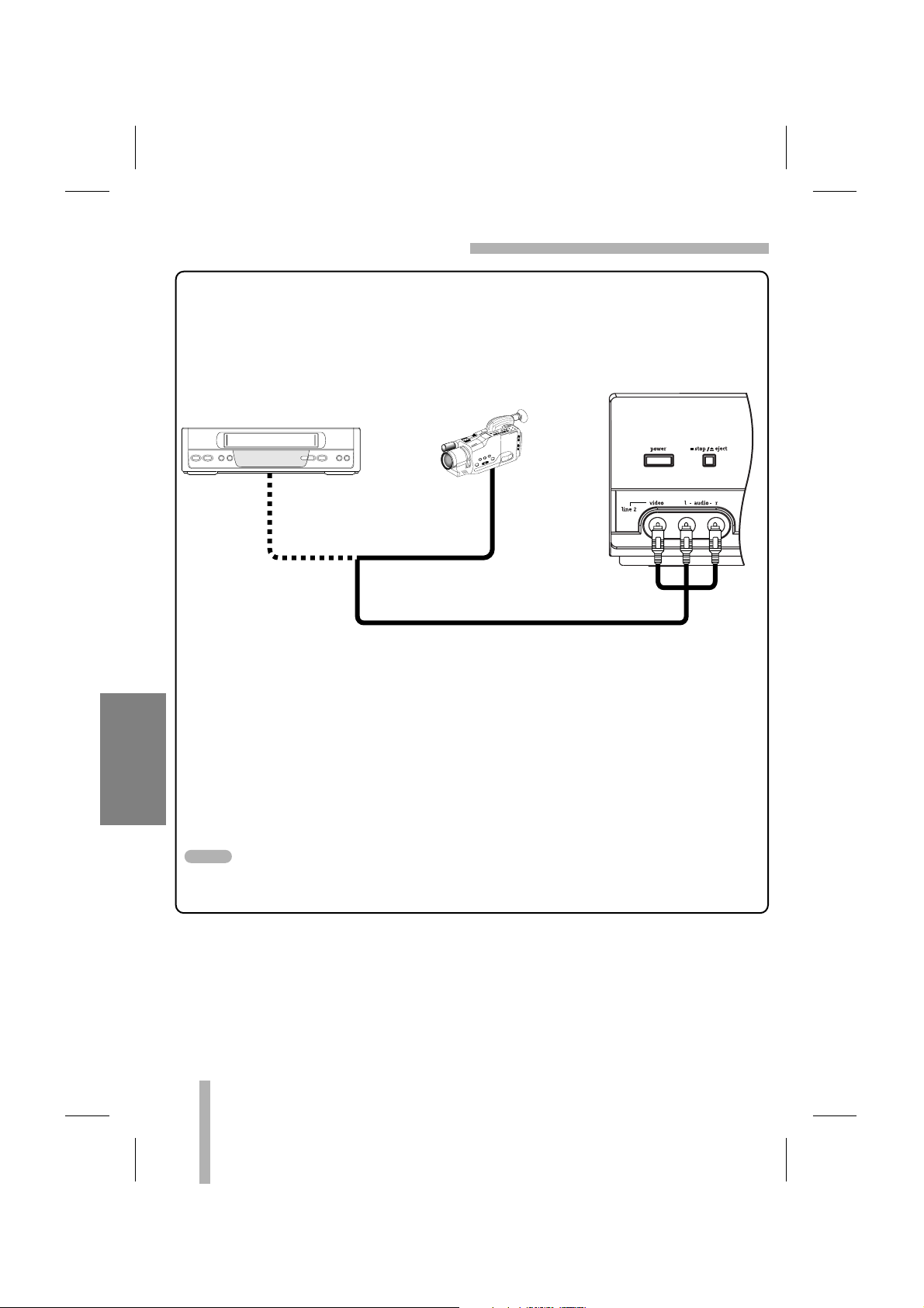
30
RECORDING
DUBBING AND EDITING
Camcorder:
Play
Another VCR: Play
Your VCR: Recording
OR
From
AUDIO and
VIDEO Output
From
AUDIO and
VIDEO Output
To AUDIO/VIDEO Input
1. Connect the camcorder’s (or another VCR’s) A/V outputs to the VCR’s front A/V inputs as
illustrated above.
2. Select the input channel “LINE2”.
• If you have connected your VCR to the A/V input jacks on the rear of VCR, you should
select the input channel LINE1.
• Select LINE1 or LINE2 A/V input channel using INPUT.
3. Play the tape in the camcorder (or another VCR). If you have a TV connected to your
VCR, you can see the video playing.
4. When you desire recording to begin, press VCR’s REC/ITR once to start.
Before recording, please confirm the recording start position.
If you wish to edit or dub your camcorder (or another VCR) recordings to this VCR, the rear
(or Front) panel mounted Audio and Video (A/V) input jacks make the connections quick and
easy. The direct A/V jacks will also provide better picture results than using the RF jack on the
rear panel.
NOTE
Page 31

31
EASY FUNCTIONS
This page explains how to operate the easy functions.
If you press PLAY, FF, REW, EJECT or REC/ITR button when
the power of this unit is off and a tape is inserted, the power
turns on automatically and then the appropriate operation will
begin as indicated below.
You can replay a specified segment twice.
To return to normal play, press EZ REVIEW again during easy
review playback.
If the Extended Data Service (XDS) signals are provided along
with normal TV signal in your area or during playback of a tape
recorded with Extended Data Service (XDS) signals, the station
ID, program title and program details are shown on the TV
screen.
When viewing a channel with Extended Data Service (XDS)
signals, press ENTER button then the station ID will appear on
the TV screen. Press ENTER button again and the program
details will appear on the TV screen.
When viewing a tape recorded with Extended Data Service
(XDS) signals, press ENTER button twice then the program
title and program details will appear on the TV screen.
Program Details
Length: Indicates the run length of a program.
Time Remaining: Indicates the remaining time of a program.
Rating: Indicates the rating of the current program (N/A, G, PG,
PG-13, R, NC-17, X and Not Rated). The rating N/A means that
the motion picture ratings are not applicable to this program.
EASY INFORMATION
EASY REVIEW
EASY OPERATION
Easy Information Screen
(Program details)
Easy Information Screen
(Station ID)
CH 4
SP WABC STEREO
“Home video”
JUL 5 , SAT 2:15 PM
PROGRAM DETAILS
“Home video”
LENGTH 01:00
TIME REMAINING 00:26
RATING N/A
eject
power
menu clear
sp / slptv / vcr
stop
rew play ff
cm skip
EZ review
pause slow
rec / itr
ch/trk
adj
enter
ch/trk
adj
input
1. During playback, press and hold EZ REVIEW for more
than 3 seconds at the end of the segment and your VCR
will start reverse search.
2. Release EZ REVIEW at the beginning of the segment.
The segment is replayed twice automatically.
Press Operation
PLAY Power On → Play back the tape
FF Power On → Fast-forward the tape
REW Power On → Rewind the tape
EJECT Eject the tape → Power Off
REC/ITR Power On → Enter pause record mode
If a cassette with no safety tab is loaded, the cassette
will be ejected automatically.
ADDITIONAL INFORMATION
Page 32

32
VHS Hi-Fi STEREO SYSTEM/MTS BROADCAST
ADDITIONAL INFORMATION
This VCR is equipped with the VHS Hi-Fi audio sound system for
recording and playback. The information below gives a brief
description of Hi-Fi audio and how to record and play a tape in
the Hi-Fi audio mode.
A stereo TV with AUDIO/VIDEO input jacks or a stereo audio system is required for true stereo playback. To experience the full and
rich stereo sound available with Hi-Fi recorded tapes, we recommend connecting your VCR to a home stereo audio system.
(STEREO) POSITION: The left channel sound (L) is heard from
the left speaker and the right channel sound (R) is heard from
the right speaker.
(LEFT) POSITION: The left channel sound (L) is heard from both
speakers.
(RIGHT) POSITION: The right channel sound (R) is heard from
both speakers.
Adjust volume at your stereo system.
PLAYBACK WITH Hi-Fi STEREO AUDIO SOUND
1.
Set the AUDIO MODE option to HI-FI on the SETUP menu.
2. Set the AUDIO OUTPUT option to STEREO position.
3. Insert a cassette and press PLAY.
To enjoy a Hi-Fi stereo system, connect your VCR’s AUDIO
(R/L)/VIDEO OUT jacks to the AUDIO (R/L)/VIDEO INPUT
jacks on back your TV (or another A/V system) using A/V
cables.
FUNCTION OSD : ON
LANGUAGE SELECT:ENGLISH
AUDIO MODE: HI-FI
BROADCAST TYPE: STEREO
AUDIO OUTPUT: STEREO
CHANNEL MAPPING
SELECT
TO EXIT PRESS
FUNCTION OSD : ON
LANGUAGE SELECT:ENGLISH
AUDIO MODE: HI-FI
BROADCAST TYPE: STEREO
AUDIO OUTPUT: STEREO
CHANNEL MAPPING
SELECT
TO EXIT PRESS
ADJUST
ADJUST
Page 33
33
ADDITIONAL INFORMATION
VHS Hi-Fi STEREO SYSTEM/MTS BROADCAST (Cont’d)
The VCS342 VCR will decode MTS stereo and bilingual (SAP)
off-the-air broadcast sound signals. It also decodes stereo TV
sound from local cable companies, as long as they operate on
assigned cable frequencies and use the EIA-recommended MTS
stereo/bilingual TV sound system.
MULTICHANNEL TV SOUND INDICATOR (MTS)
Appears on the screen as illustrated on the left when ENTER is
pressed.
• One or both of the indicators will light, depending on the MTS
broadcast.
If only STEREO appears on the TV screen.
The VCR can record in stereo onto the VHS Hi-Fi audio tracks
when BROADCAST TYPE is in the STEREO position. The VCR
will also record mono audio onto the mono audio track.
If only SAP appears on the TV screen.
Set BROADCAST TYPE to SAP.
If both the STEREO/SAP appear on the TV screen
Use the BROADCAST TYPE option to select the desired recording mode (STEREO or SAP).
Some stations transmit a Second Audio Program, which is used
for a second language or additional information. When the station broadcasts a Second Audio Program, follow the procedure
below to record the SAP.
You are now recording the program you see and hear on the TV.
SAP (Second Audio Program) RECORDING
MTS (Multi-Channel TV Sound)
1. Insert a video cassette with the safety tab in place.
2.
Set the BROADCAST TYPE option to SAP (SETUP menu).
Do this if only SAP appears on the TV screen or you know
the program has SAP.
3. Set the desired speed (SP or SLP) by pressing SP/SLP.
4. Select the desired channel. SAP should appear on the TV
screen.
5. Press REC/ITR once.
6. Press STOP to stop recording.
CH 4
STEREO/SAP
STEREO
Lights up when a stereo
broadcast is being
received.
SAP
Lights up when a SAP
BILINGUAL broadcast is
being received.
TV screen
FUNCTION OSD : ON
LANGUAGE SELECT:ENGLISH
AUDIO MODE: HI-FI
BROADCAST TYPE: SAP
AUDIO OUTPUT: STEREO
CHANNEL MAPPING
SELECT
TO EXIT PRESS
ADJUST
Page 34

34
TAPE COUNTER MEMORY FEATURE
ADDITIONAL INFORMATION
Shows length of tape run in hours, minutes, and seconds (refer
to the left). Press ENTER to select the real-time counter display.
Each additional press of ENTER changes the counter display as
shown left.
• Counter changes to 0:00:00 when a cassette is ejected.
• The real-time counter does not operate if nothing is recorded
on the tape.
• The real-time counter only works if a tape is in the VCR.
This is useful if there is a section of tape you want to view immediately after recording or if you want to return to the same point
several times.
The tape automatically stops when the tape counter returns to
about “0:00:00”.
COUNTER MEMORY FUNCTION
REAL-TIME COUNTER
1. Begin recording or playing a tape.
2. Press ENTER repeatedly to display the real-time counter
on the TV screen.
3. At the point you want to locate later, reset the real-time
counter to 0:00:00 by pressing CLEAR.
4. Continue to play or record.
5. Press STOP when recording or playback finishes.
6. Press REW.
eject
power
menu clear
sp / slptv / vcr
stop
rew play ff
cm skip
EZ review
pause slow
rec / itr
ch/trk
adj
enter
ch/trk
adj
input
2:15 AM
0:05:25
REM 1:07
Indicator Panel
TV Screen
TAPE REMAINING
This function allows the time of the remaining tape to be displayed during recording or playback.
The remaining tape length indicator may not be displayed
correctly depending on the condition and type of tape (T-120,
T-140, or T-160 etc)
CLOCK
COUNTER
REMAINING TIME
Indicator Panel TV Screen
Press ENTER repeatedly until the REM indicator appears
during recording or playback.
REM 1:07
NOTE
Page 35

35
ADDITIONAL INFORMATION
EDITING A RECORDING
OPERATING HINTS
The program material to be recorded will appear on the television.
The new program material will directly follow the previously
recorded material. This feature is especially helpful during camcorder-to-VCR dubbing use so each segment of the recording
becomes a continuous program.
• In manual recording, Timer recording, Instant Timer
Recording, playback, or fast forward modes, the VCR automatically starts rewinding the tape when the end of the tape
is reached. The cassette will rewind and stop at the beginning of the tape, be ejected, and the VCR will turn itself off.
• After you have finished using the VCR, rewind, eject, and
remove the cassette. Place the cassette in its protective
sleeve to protect it from dust. It is not necessary to rewind the
cassette before removing it, but if you do, it will be ready to
play or record the next time you use it.
• Be sure the VCR Channel Selector is on the correct channel
you wish to record. The channel that is being recorded can
always be checked by tuning the television to the VCR
channel (3 or 4) and pressing the TV/VCR selector to turn
the VCR’s VCR indicator on.
• Do not attempt to hook up more than one television set to the
VCR for either recording or playback.
1.
Press PLAY and watch the program until you reach the
exact point where you want the new recording to start.
2. Press PAUSE.
3. Press REC/ITR once.
4. When you wish to start recording, press PAUSE again.
eject
power
menu clear
sp / slptv / vcr
stop
rew play ff
cm skip
EZ review
pause slow
rec / itr
ch/trk
adj
enter
ch/trk
adj
VIDEO HEAD CLEANING
• Whenever a video cassette is inserted into or ejected from
this unit the video head is automatically cleaned.
• However, it is possible that the heads may become clogged
when playing an old or damaged tape. If the image on your
screen resembles the picture on the left while playing back a
tape, the heads may require cleaning.
• To clean the heads, obtain a head cleaning tape from your
local video dealer. Follows the instructions that come with the
cleaning tape, as excessive use can shorten head life.
Page 36

36
ADDITIONAL INFORMATION
TROUBLESHOOTING
• Load cassette in direction indicated by arrow on cassette.
• A cassette is already in the VCR.
• Check if the VCR indicator panel is lit. If not, make sure power
cord is plugged in.
• If the indicator flashes, press POWER again.
• Use TV/VCR to select the VCR mode.
• Tune the television to the same channel selected on the VCR
output channel select switch. (CH3 or CH4).
• Adjust the Tuning Control on the television to obtain the best
picture.
• The cassette has had the safety tab removed. Paste a piece of
cellophane tape over the safety tab hole or use a different
cassette.
• Tune the television to the VCR channel (3 or 4) depending on
the selected channel on the back of the VCR. (Output Channel).
• Try a different cassette tape.
• The heads may require cleaning.
• Take VCR to a qualified Service Center for service.
• Adjust fine tuning knob on television set to obtain best picture.
• Adjust the tracking control.
• Take VCR to Service Center for service.
• Weak or dead batteries.
• Remote IR signal to sensor on VCR being blocked.
• Reset time according to instructions. Power has been interrupted.
• Set up recording time according to instructions.
• Be sure the AM-PM setting on display is correct.
• VCR must be turned off for Timer to work.
• The cassette has had the safety tab removed. Stick a piece of cello-
phane tape over the safety tab hole or select a different cassette.
• Insert a cassette.
• The TV station sent the wrong XDS information. Use the Manual
Clock Set procedure on page 20.
Cassette cannot be inserted.
No picture appears on TV
screen.
A picture appears on TV screen
but is not clear.
The VCR will not go into the
recording mode, even when
REC/ITR is pressed.
No picture appears on television
screen when PLAY is pressed.
No picture, but audio is clear.
Interference on playback
picture.
Remote does not work.
“--:--” appears on the indicator
panel.
VCR does not start at preset
record starting time.
The tape is ejected in the timer
mode.
indicator flashes.
The Auto Clock Setup procedure
enters the wrong date and/or time.
SYMPTOM CHECKPOINT & POSSIBLE SOLUTION
Page 37

37
ADDITIONAL INFORMATION
SPECIFICATIONS
Head System Four head helical scan azimuth system
Power Source AC 120V, 60Hz
Power Consumption Approx. 12 Watts
Dimensions (WxHxD) 360 x 94.5 x 230 mm (14.3” x 3.8” x 9.2”)
Operating Temperature 5 °C - 35 °C (41 °F - 95 °F)
Operating Humidity Less than 80% RH
Timer 12-hour display type with AM, PM
Weight Approx. 3.2 kg (7 lbs)
Tape Speed (SP) 33.35 mm/sec
(LP) 16.67 mm/sec
(SLP) 11.12 mm/sec
Tape Width 12.7 mm
Maximum Recording Time (SP) 2 HOURS (T-120)
(SLP) 6 HOURS (T-120)
8 HOURS (T-160)
Rewind Time about 3 minutes (T-120)
Antenna (UHF) 75 ohms
(VHF) 75 ohms
VHF Output Signal Channel 3 or 4 (Switchable)
Channel Coverage (VHF) 2-13
(UHF) 14-69
(CATV) 1-125 (4A, A-W, W+1 - W+84, A-5 - A-1)
Video Signal System EIA Standard (525 lines, 60 fields)
NTSC type color signal
Input 1.0 Vp-p 75 ohms unbalanced
Output 1.0 Vp-p 75 ohms unbalanced
Signal to Noise Ratio More than 43 dB (SP mode)
FM audio (VCS342 only)
Frequency Range 20Hz to 20kHz
Dynamic Range More than 83 dB
Channel Separation More than 55 dB
Conventional audio
Input (LINE) -6.0 dBm more than 47 kohms
Output (LINE) -6.0 dBm less than 1.0 kohms
S/N Ratio More than 43 dB (SP mode)
Frequency Range 200 Hz to 10kHz (SP mode)
* Designs and specifications are subject to change without notice.
* Weight and dimensions shown are approximate.
AUDIO
VIDEO
TUNER
GENERAL
Page 38

Zenith will repair or replace your product, at Zenith’s option, if it proves to be defective in material or workmanship under normal use,
during the warranty period (“Warranty Period”) listed below, effective from the date (“Date of Purchase”) of original consumer purchase
of the product. This warranty is good only to the original purchaser of the product and effective only when used in the United States,
excluding U.S. Territories.
THIS WARRANTY IS IN LIEU OF ANY OTHER WARRANTIES, EXPRESS OR IMPLIED, INCLUDING WITHOUT LIMITATION, ANY WARRANTY OF MERCHANTABILITY OR FITNESS FOR A PARTICULAR PURPOSE. TO THE EXTENT
ANY IMPLIED WARRANTY IS REQUIRED BY LAW, IT IS LIMITED IN DURATION TO THE EXPRESS WARRANTY
PERIOD ABOVE. ZENITH WILL NOT BE LIABLE FOR ANY CONSEQUENTIAL, INDIRECT, OR INCIDENTAL DAMAGES OF ANY KIND, INCLUDING LOST REVENUES OR PROFITS, IN CONNECTION WITH THE PRODUCT. SOME
STATES DO NOT ALLOW LIMITATION ON HOW LONG AN IMPLIED WARRANTY LASTS OR THE EXCLUSION OF
INCIDENTAL OR CONSEQUENTIAL DAMAGES, SO THE ABOVE LIMITATIONS OR EXCLUSIONS MAY NOT APPLY
TO YOU.
THIS LIMITED WARRANTY DOES NOT APPLY TO:
1. Damages or operating problems that result from shipping, installation, adjustment of user controls, calibration, maintenance or failure to maintain, or separate system components; and
2. Damages or operating problems that result from normal wear and tear, misuse, abuse, operation outside environmental specifications
or contrary to the requirements or precautions in the Operating Guide, accident, lightning strikes or other natural causes, unauthorized modification or alteration, incorrect electrical current or voltage, software errors that do not disable functionality, operating
software protocols adopted after the date of manufacture or for outside the U.S., institutional or commercial use, or other causes not
arising out of defect in material or workmanship.
3. Therefore, the cost of repair or replacement of such a defective product shall be borne by the consumer.
CUSTOMER INTER-ACTIVE CENTER NUMBERS:
FOR WARRANTY SERVICE:
You must call 1-800-984-9349 (Monday ~ Friday, 7 AM to 8 PM CT) and select appropriate option from the menu to confirm the product
is defective and to obtain Return Authorization (RA). During the Warranty Period, Zenith will send you a return-shipping label. After you
obtain RA for return, please box your unit with a copy of the sales receipt and enough packing material to ensure undamaged delivery of
your product. When you receive the label, place it on the box and call the 800 # in the instruction for pick-up. When your unit is received,
Zenith will repair or replace your unit in accordance with this Limited Warranty.
ADVANCE SHIPMENT. If replacement unit is available and you want second day delivery, our service representative will ask for your
credit card number. Zenith requires a reserved deposit by credit card as surety for such advance shipment. Your credit card will not be
charged if you return the defective unit in 10 business days. For advance shipment, the return label will come with the replacement unit
sent to you. Please follow boxing and shipping instructions above.
ZENITH ELECTRONICS CORPORATION Zenith Part No. 206-3868
2000 MILLBROOK DRIVE GS# 3834RM0057T
LINCOLNSHIRE, IL 60069 Printed in Indonesia
Issue O
WARRANTY PERIOD:
LABOR: 90 DAYS from the Date of Purchase.
PAR TS: ONE YEAR from the Date of Purchase.
Repaired or Replacement Units are warranted for the remain-
ing period of the original warranty.
HOW
SERVICE IS HANDLED:
Call 1-800-984-9349 for instructions on getting the defective
unit repaired or replaced.
Please retain dated sales receipt and your box to return the
unit to Zenith for repair or replacement.
Both ways shipping charges will be borne by Zenith during the
Warranty Period. After the Warranty Period, you pay in-bound
shipping charges and Zenith pays return shipping charges.
For Warranty Service
For Post Warranty Repair
For Where-to buy, Product Assistance, or
Customer Assistance
Call 1-800-984-9349 (Monday ~ Friday, 7 AM ~ 7 PM CT)
Retain your dated sales receipt to prove the Date of Purchase as well as your box for
shipping the unit to Zenith, for warranty service.
Legible copy of your sales receipt must be submitted with the unit at the time the unit
is returned for warranty service.
For repair or replacement after the Warranty Period has expired,
Call 1-800-984-9349 (Monday ~ Friday, 7 AM ~ 7 PM CT)
Call 1-877-9 Zenith (1-877-993-6484) (Monday ~ Friday, 7 AM ~ 8 PM CT and
Saturday, 8 AM ~ 5 PM CT) and select an appropriate option from the menu.
Or visit our website at http://www.zenithservice.com
ZENITH ELECTRONICS CORPORATION
VCR LIMITED WARRANTY-USA
 Loading...