

Page 1
Advanced Video Imaging
iAviso para nuestros
clientes de habla hispana:
cons'uite la informacibn que
aparece al final de este manual!
recycled paper
50 percent
Direct-View Color TV
Closed Captions
MTS Stereo Audio
Surround Sound
Return the Product Registration
Card, and your TV could be free!
Page 2
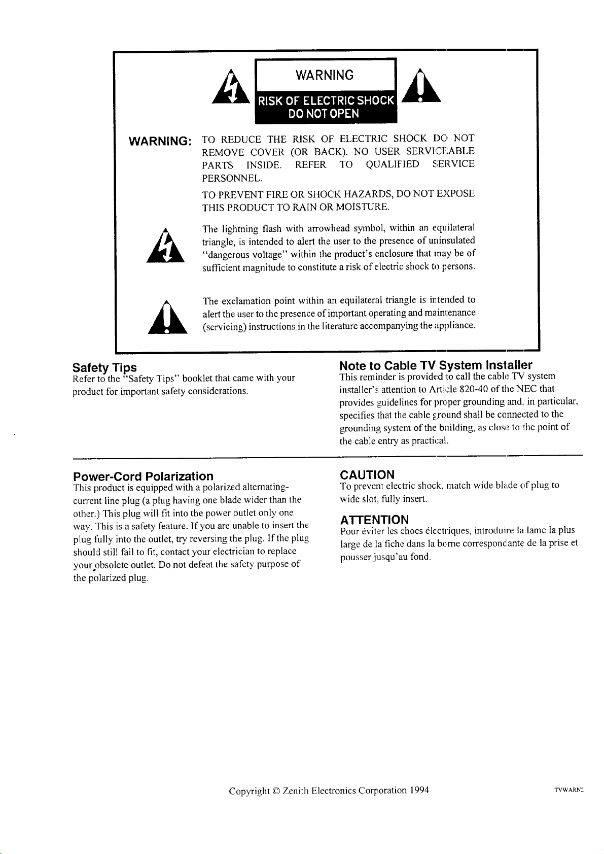
WARNING:
TO REDUCE THE RISK OF ELECTRIC SHOCK I)O NOT
REMOVE COVER (OR BACK). NO USER SERVICEABLE
PARTS INSIDE. REFER TO QUALIF'IED SERVICE
PERSONNEL.
TO PREVENT FIRE OR SHOCK HAZARDS, DO NOT EXPOSE
THIS PRODUCT TO RAIN OR MOISTURE.
The lightning flash with arrowhead symbol, within an equilateral
triangle, is intended to alert the user to the presence of uninsulated
"dangerous voltage" within the product's enclosure that may be of
sufficient magnitude to constitute a risk of electric shock to persons.
alert the user to the presence of important operating and maintenance
The exclamation point within an equilateral triangle is intended to
(servicing) instructions in the literature accompanying the appliance.
Safety Tips
Refer to the "Safety Tips" booklet that came with your
product for important safety considerations.
Power-Cord Polarization
This product is equipped with apolarized alternating-
cun'ent line plug (a plug having one blade wider than the
other.) This plug will fit into the power outlet only one
way. This is a safety feature. If you are unable to insert the
plug fully into the outlet, try reversing the plug. If the plug
should still fail to fit, contact your electrician to replace
your obsolete outlet. Do not defeat the safety purpose of
the polarized plug.
Note to Cable TV System Installer
This reminder is provided to call the cable "IV'system
installer's attention to Article 820-40 of the NEC that
provides guidelines for proper grounding and, in particular,
specifies that the cable ground shall be connected to the
grounding system of the building, as close to the point of
the cable entry as practical.
CAUTION
To prevent electric shock, match wide blade of plug to
wide slot, fully insert.
ATTENTION
Pour dviter les chocs _lectriques, introduire la lame la plus
large de la fiche dans la bc.rne correspondante de la prise et
pousser jusqu'au fond.
Copyright © Zenith Electronics Corporation 1994 TVWARN2
Page 3
CONTENTS
INTRODUCTION
Welcome ......................................... ii
Installation Considerations ........................... ii
CONNECTIONS FOR YOUR TV
Connection Center on Back of TV .................... 1-1
Other A/V Jacks on TV ............................. 1-1
Step 1.Make Basic Connection to TV ................. 1-2
Step 2. Make VCR Connections to TV ................. 1-3
Step 3. Make Super-VHS VCR Connections to TV ....... I-4
Step 4. Make: A/V Connections to Auxiliary
A/V Jacks (VIDEO 3 IN or S-VIDEO 2 IN) .......... 1-4
Step 5. Make Surround Sound Connections to TV ........ 1-4
Step 6. Make External Speaker Connections to TV ....... 1-5
Step 7. Make Audio Connection to Stereo Amplifier ...... 1-5
THE FIRS]" TIME YOU OPERATE YOUR TV
Step 1. Connect the Power ........................... 2-1
Step 2. Select Your Viewing Source ................... 2-1
Step 3. Use Auto Program ........................... 2-1
Step 4. Time Functions ............................. 2-1
Step 5. Use Other Options ........................... 2-2
REMOTE CONTROL MODEL SC2400
Operation ........................................ 3-1
Installing Batteries ................................. 3-1
REMOTE CONTROL MODEL MBR3420
Operation ........................................ 4- l
Choose the Operating Mode ......................... 4-l
TV Operations .................................... 4-2
VCR Operations .................................. 4-3
Cable-TV Operations ............................... 4-4
Preparation for Use ................................ 4-5
Installing Batteries ................................. 4-5
REMOTE CONTROL MODEL MBR3430
Operation ........................................ 5-l
Choose the Operating Mode ......................... 5-1
TV Operations .................................... 5-2
VCR Operations ......... '......................... 5-3
Cable-TV Operations ............................... 5-4
Preparation for Use ................................ 5-5
Installing Batteries ................................. 5-5
Programming Brand Codes .......................... 5-6
TV, VCR and Cable-TV Operating Codes .............. 5-7
QUICK REFERENCE TO ON-SCREEN MENUS
Available Menus .................................. 6-1
Summary ,ofMenu Items ............................ 6-1
Menu Operation Example ........................... 6-3
SOURCE MENU
Source Se[ection .................................. 7-1
Source Identification ............................... 7-1
SETUP MENU
Auto Program .................................... 8-1
Ch. Add/Del ...................................... 8-I
Ch. Labels ........................................ 8-2
Tuning Band ..................................... 8-3
Auto Tuning ..................................... 8-3
Source ID ........................................ 8-3
Clock Set ........................................ 8-4
Captions ......................................... 8-4
AUDIO MENU
Bass ............................................ 9-I
Treble ........................................... 9-1
Balance ......................................... 9-1
Audio ............................................ 9-I
SEQ ............................................. 9-1
Surround ......................................... 9-1
VIDEO MENU
Contrast ........................................ 10-1
Brightness ...................................... I0-1
Color .......................................... 10-1
Tint ............................................ 10-1
Sharpness ....................................... 10-1
Color Temp ..................................... 10-1
Video Filter ..................................... 10-1
Auto Flesh ...................................... 10-1
Picture Pref ..................................... 10-1
PIP MENU
Ch. Guide ....................................... 11-1
Ch. Review ..................................... 11-2
PiP Source ...................................... 11-2
PiP Size ....................................... 11-3
PiP Color ........................................ 11-3
PlP Tint ......................................... 11-3
PIP OPERATION AND CONNECTIONS
PIP Overview ................................... 12-I
Typical Connections .............................. 12-1
How to Select Main Picture & PIP Source ............. 12-3
PIP Functions ................................... 12-4
MAINTENANCE AND TROUBLESHOOTING
Caring for Your TV ................................ 13-1
Extended Absence ................................ 13-1
TV Picture Interference ............................ 13-1
Before Calling for Service .......................... 13-2
Product Registration Card
Recommended Accessories For Your Television
Aviso para nuestros clientes de habla hispana
Your Zenith Warranty
HOW TO USE YOUR OPERATING GUIDE
THIS OPERATING GUIDE DESCRIBES A FAMILY OF TV MODELS. SOME MODELS HAVE FEATURES THAT ARE
NOT PROVIDED ON OTHER MODELS, SUCH AS AUXILIARY JACKS OR TWO REMOTE CONTROL,S. DIFFERENT
CONTROL PANELS AND REMOTE CONTROLS MAY BE USED FROM MODEL-TO-MODEL. REFER TO THE APPLI-
CABLE SECTIONS OF THIS OPERATING GUIDE FOR THE FEATURES AND ITEMS PROVIDED WITH YOUR TV.
2735-0 i
Page 4
WELCOME
INTRODUCTION
Welcome into the family of Zenith Color Television owners.
This guide provides instructions on how to operate your new
TV. It is supplemented by a booklet containing Safety Tips.
We urge you to read these publications carefully so that you
will receive full enjoyment from your new Zenith TV for
many years to come.
Your new TV has been designed and built to give you the very
best in quality, features and performance. There are thousands
of Zenith authorized service centers throughout the U.S.,
Canada and Mexico who can attend promptly and effectively
to ordinary service needs.
If you should have an unusual performance or service problem
that cannot be satisfactorily resolved by your Zenith dealer or
Zenith authorized service center, contact us at:
INSTALLATION CONSIDERATIONS
Before you install your TV...
Ventilation -- Proper ventilation keeps your TV
running cool. Air circulates through perforations
in the back and bottom of the cabinet. Do not
block these vents or you will shorten the life of
your TV.
on normal household current, 120 volt 60 Hertz AC.
Power Source -- Your TV is designed to operate
Do not attempt to operate it on DC current.
Power Cord -- Your power cord has a polarized
plug as required by Underwriters' Laboratories. It
has one regular blade and one wide blade and fits
only one way into a standard electrical outlet. If
the blades will not enter either way, your outlet is
very old and non-standard. A new outlet should be
installed by a qualified electrician.
Zenith Electronics Corporation
Customer Service Department
1000 Milwaukee Avenue
Glenview, IL 60025-2493
Telephone: (_147)391-8752
Mon-Fri, 8:00 a.m. - 4:30 p.m. Central Time
Provide the model number, sc_,rialnumber, and date of pur-
chase or original installation, with a full explanation of the
problem and the service hi,;tory. We will welcome the opportu-
nity to look into your specific question or problem and to be
of assistance in resolving it promptly.
The model a2adserial numb_.,rsof your new TV are located on the
back of the TV cabinet. For your future convenience andprotec-
tion, we suggest that you recor,:lthese numbers here:
Model No.
Serial No.
Please read and observe each safety point in t:he "Safety
Tips" folder when installing and using your TV.
VIDEO GAMES AND O TtlER FIXED
PATTERN DISPLAY CAUTION -- If you use your TV for
video games, teletext or other fixed displays, avoid setting the
BRIGHTNESS control for an excessively bright picture. A
bright, fixed pattern, if used for long periods of time, can re-
sult in a permanent imprint o_1the TV pictme tube. You can re-
duce this possibility by alternating the use of the fixed pattern
display with normal TV pi,:t_re viewing, by turning down the
CONTRAST control for sustained fixed pat'Iern use, and by
turning off the fixed pattern clisplay when not in use.
PLUGGING IN YOUR TV -- Be sure to plug your TV into
an "unswitched" AC power source. The "switched" AC out-
lets found on some video equipment will not continue supply-
ing power to the qw once the equipment is turned off. If the
power to the TV is interrupted, you will have to reset the clock
in the TV to the current time.
Safe Operation -- Your TV is manufactured and
tested with your safety in mind. However, unusual
stress caused by dropping or mishandling, expo-
sure to flood, fire, rain or moisture, or accidental
spilling of liquids into the TV, can result in poten-
tial electrical shock or fire hazards. If this hap-
pens, have your TV checked by a service
technician before using it again.
rvwEoi_ ii
Page 5
CONNECTIONS FOR YOUR TV
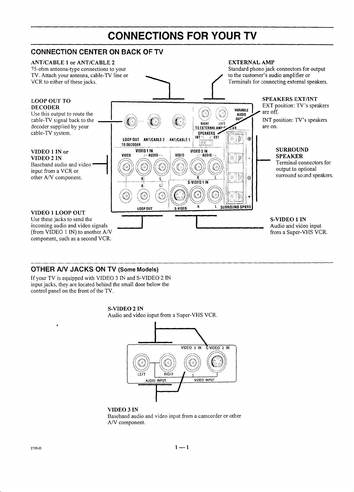
CONNECTION CENTER ON BACK OF TV
ANT/CABLE 1 or ANT/CABLE 2
75-ohm antenna-type connections to your
TV. Attach your antenna, cable-TV line or
VCR to either of these jacks.
LOOP OUT TO
DECODER
Use this output to route the
cable-TV signal back to the
decoder supptied by your
cable-TV system.
VIDEO 1 IN or
VIDEO 2 IN |
Baseband audio and video
input from a VCR or
other A/V component.
VIDEO 1 LOOP OUT
Use these jacks to send the
incoming audio and video signals
(from VIDEO 1IN) to another A!V
component, :such as a second VCR.
--3
I
TODECODER
VIDEO :-AUDIO_
LOOPOUT ANT/CABLE2
VIDEO1 IN
L:
@
LOOP OUT
lO EXTERNAL AMPt
i IGHT LEFT
SPEAKERS
INT-7 v EXT
ANT/CABLE1 i_ _
IL VIDEO2 IN
VIDEO r- AUDIO_
R L
S-VIDEO1 IN
S-VIDEO R
!
EXTERNAL AMP
Standard phono jack connectors flgroutput
to the customer's audio amplifier or
Terminals figr,connecting external speakers.
SPEAKERS EXT/INT
VARIABLE
AUDIO
SURROUNDSPKRS
EXT position: TV"s speakers
areoff.
INT position: TV's speakers
are on.
SURROUND
SPEAKER
Terminal connectors for
outputto optional
surround so and speakers.
S-VIDEO 1 IN
Audio and video input
from a Super-VHS VCR.
OTHER AN JACKS ON TV (Some Models)
If your TV is equipped with VIDEO 3 IN and S-VIDEO 2 1N
input jacks, they are located behind the sma|l door below the
control panel on the front of the TV.
S-VIDEO 2 IN
Audio and video input from a Super-VHS VCR.
I
I
VIDEO 3 IN
Baseband audio and video input from a canlcorder or other
A/V component.
\
VIDEO 3 IN _-VIDEO 2 IN
2735-0 1_ 1
Page 6
CONNECTIONS FOR YOUR TV
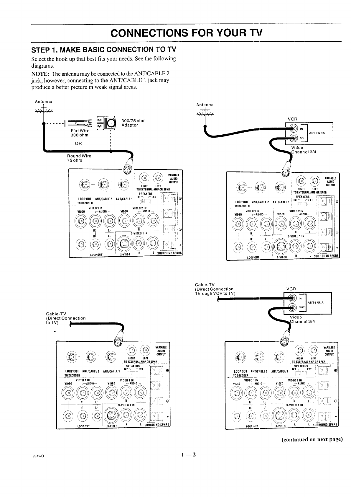
STEP 1. MAKE BASIC CONNECTION TO TV
Select the hook up that best fits your needs. See the following
diagrams.
NOTE: The antenna may be connected to the ANT/CABLE 2
jack, however, connecting to the ANT/CABLE jack may
produce a better picture in weak signal areas•
Antenna
Antenna
300/75 ohm
Flat Wire
300 ohm
OR
i
Round Wire
75 ohm
LOOP OUT ANT/CABLE2 AHT/CADLE 1 _ :"
sonEc0oE, i _-_!
VIDEO [--AUOIO l VIDEO _- AUDIO
@
VIDEO 1 IN VIDEO 2 IN
i RI L
i .-V,DEO,,.
LOOPQUT
Adaptor
l
i
l
i
I
} j=IANTENNA]
I
i '_.' '.... / oo_
/
}
! RIGHT LEFT
I TO EXTERNAL AMP ORSPKR
SPEAKERS
i INT_ rEl'f
R L
L SURROUND SPKRS
it' ( o ' ,) LEFT
LOOP OUT ANT/CADLE2 ANT/CASLE 1
._ TO DECODER .... _ ...... i;
VIDEO 1 IN VIDEO 2 IN i)
VIDEO r-AUDIO / VIOEO AUDIO 1 ([_ I'_
-; ........ • S-Vi6E01IN Iv_' ,:_
i R L
LOOPOUT S-VIDEO R L SURROUND SPKRS
VCR
"_ _Vihdaen%,e, 3/4
\ VM_ImE
_1 @ AUDIO
_]_ OUTPUT
• TO EI(TERNAL AMP ORSPKR _
SPEAKERS
INT-I I EIT
Cable-TV
(Direct Connection
to TV)
27_s-o l --2
Cable-TV
(Direct Connection
Through VCR to TV)
..... [
VCR
I "_ / ANTENNA
/ /
//_. _ OUTPUT
i_ ' ,,,)I [ !
LOOP OUT ANT/C,,BLE2 AHT/CABLE1 i_,: : :I i _ !
TO DECODER
VIDEO r AUDIO VLOEO AUDli]
! R; L_ : I!
T] _ TO EXTERI(AL AMP OR!P_R .
VIDEO, IN VIDEO 21N (<_7] TT( (]
-5
R L [! SLVIDI_0il N ,, \i _ l
LOOPI)UT S-VIDEO
; AUDIO
t, RIGHF LEFT
SPEAKERS ) F I
L SURROUND SPKRS
(continued on next page)
Page 7
CONNECTIONS FOR YOUR TV
STEP 1. MAKE BASIC CONNECTION TO TV
DECODER/
CONVERTER
. Video
I Channel 3/4
LOOPOUT ART_ABLE2 ANT/CABLE1 INT_ I-Eli _l_
TO DECODER _ J
VIDEO 1 IN I VIDEO 2 IN
VIDEO r--ADOID-- VIDEO r AUO[O_ _--r_ t
": .... ]i
LOOPOLIT I $-_V_E O II L SURROUND SPKRS
SPEAKERS \ /I
R L o IlllliI®
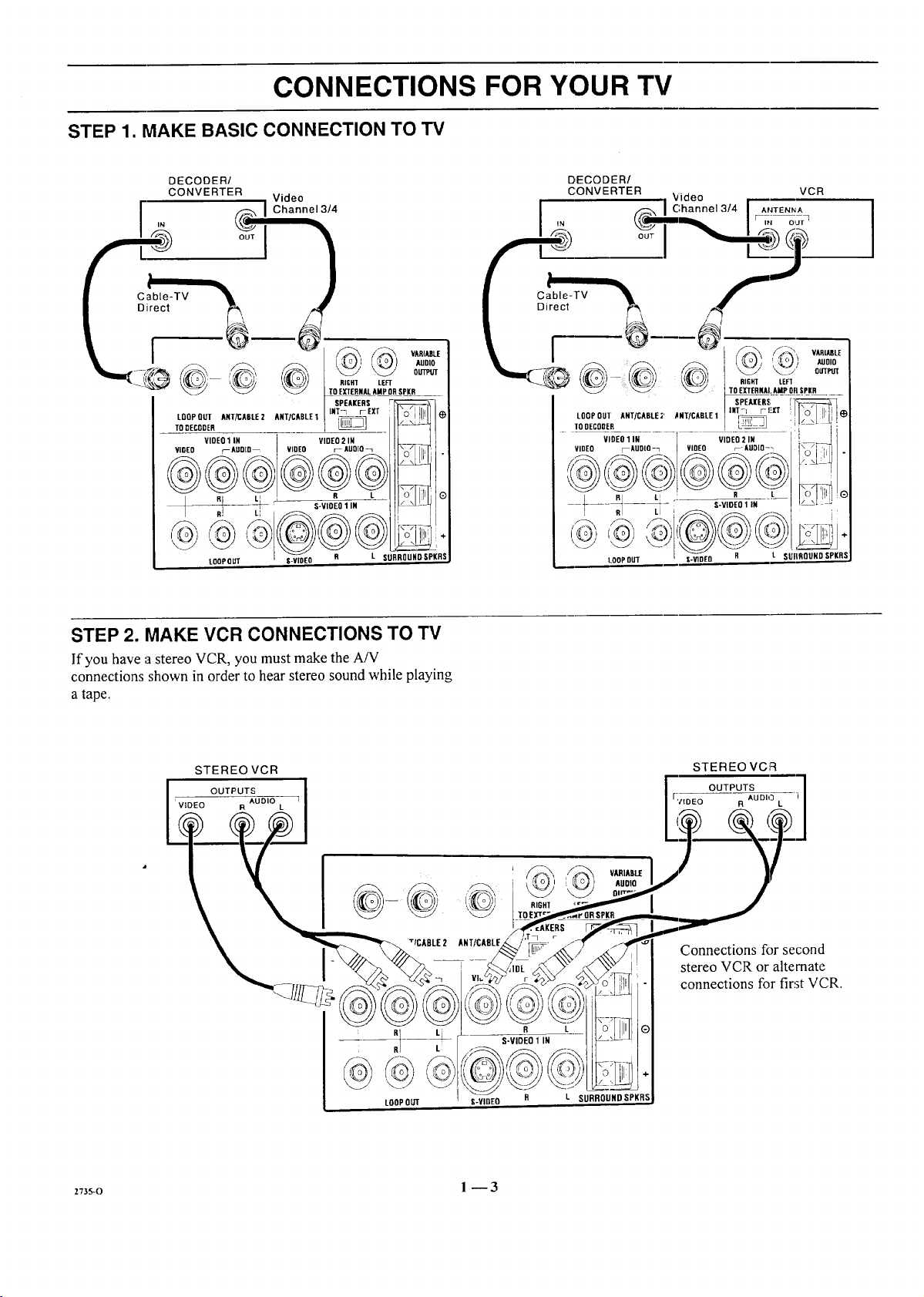
STEP 2. MAKE VCR CONNECTIONS TO TV
If you have astereo VCR, you must make the A/V
connections shown inorder to hear stereo sound while playing
a tape.
_7_o 1 -- 3
Page 8
CONNECTIONS FOR YOUR TV
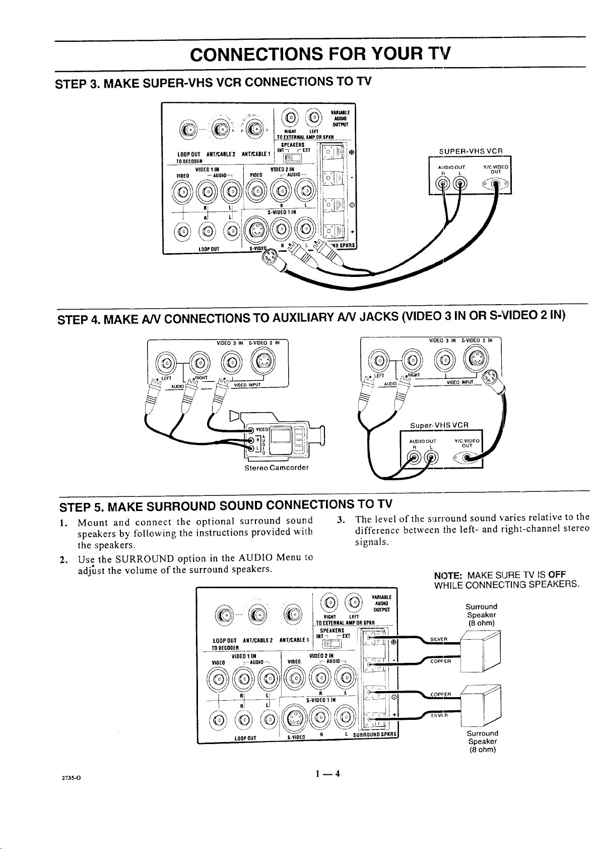
STEP 3. MAKE SUPER-VHS VCR CONNECTIONS TO TV
i_ VAAtULE
RIQHT LEFT
TO EXTERNALAMP OR SPi(R
LOOP OUT ANT/CABLE 2 ANT/CABLE1 IUT_ r EX'T
TOOECODER
VIDE0
VIOEO ,--AUOIO_ VIDEO r AUDIO_
_ : R L
1 IN t VIO(O 2 IN
LOOPOUT
STEP 4. MAKE AN CONNECTIONS TO AUXILIARY A/V JACKS (VIDEO 3 IN OR S-VIDEO 2 IN)
SPEAKERS
SUPER-VHSVCR
VIDEO 3 IN S-VIDEO 2 IN
J S:::riV FIS ::_.o _[
Stereo Camcorder
STEP 5. MAKE SURROUND SOUND CONNECTIONS TO TV
1. Mount and connect the optional surround sound
speakers by following the instructions provided with
the speakers.
2. Use the SURROUND option in the AUDIO Menu to
adjust the volume of the surround speakers.
-- RIGHT LEFT
3. The level of the surround sound varie, s relative to the
difference between the left- and right-channel stereo
signals.
to0rooTA.rX,Bt_2A,rxAot_I'"I_-_ _ !ll_',,,,'':_,
YCOEO F-AUDIO_ I VIDEO r_AUOlO_ I_ -'_ I, F I "i
VIDEO 3 IN S-VIDEO 2 IN ]
NOTE: MAKE SURE TV IS OFF
WHILE CONNECTING SPEAKERS.
Surround
Speaker
(8 ohm)
SILVER _q
R L R t C_ "_q '
R! L, !_.-__.._-_]// ILl
LOOPOUT l-VIDEO P
I R L SURROUHD $PKRS
_7_s-o l -- 4
Surround
Speaker
(8 ohm')
Page 9
CONNECTIONS FOR YOUR TV
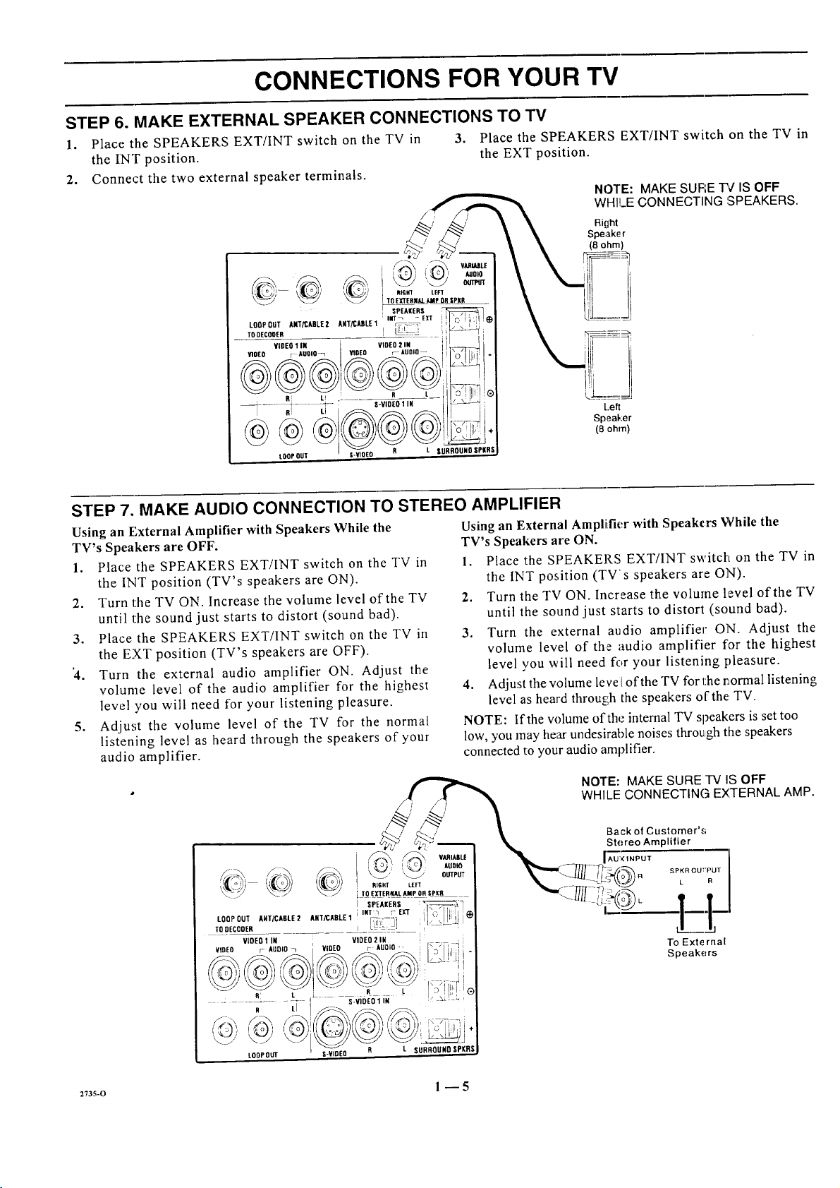
STEP 6. MAKE EXTERNAL SPEAKER CONNECTIONS TO TV
1. Place the SPEAKERS EXT/INT switch on the TV in 3. Place the SPEAKERS EXT/INT switch on the TV in
the INT position, the EXT position.
2. Connect the two external speaker terminals.
NOTE: MAKE SUFIET¢ ISOFF
WHILECONNECTING ',SPEAKERS.
Right
Speaker
(8 ohm)
Left
Speal,:er
(8 ohm)
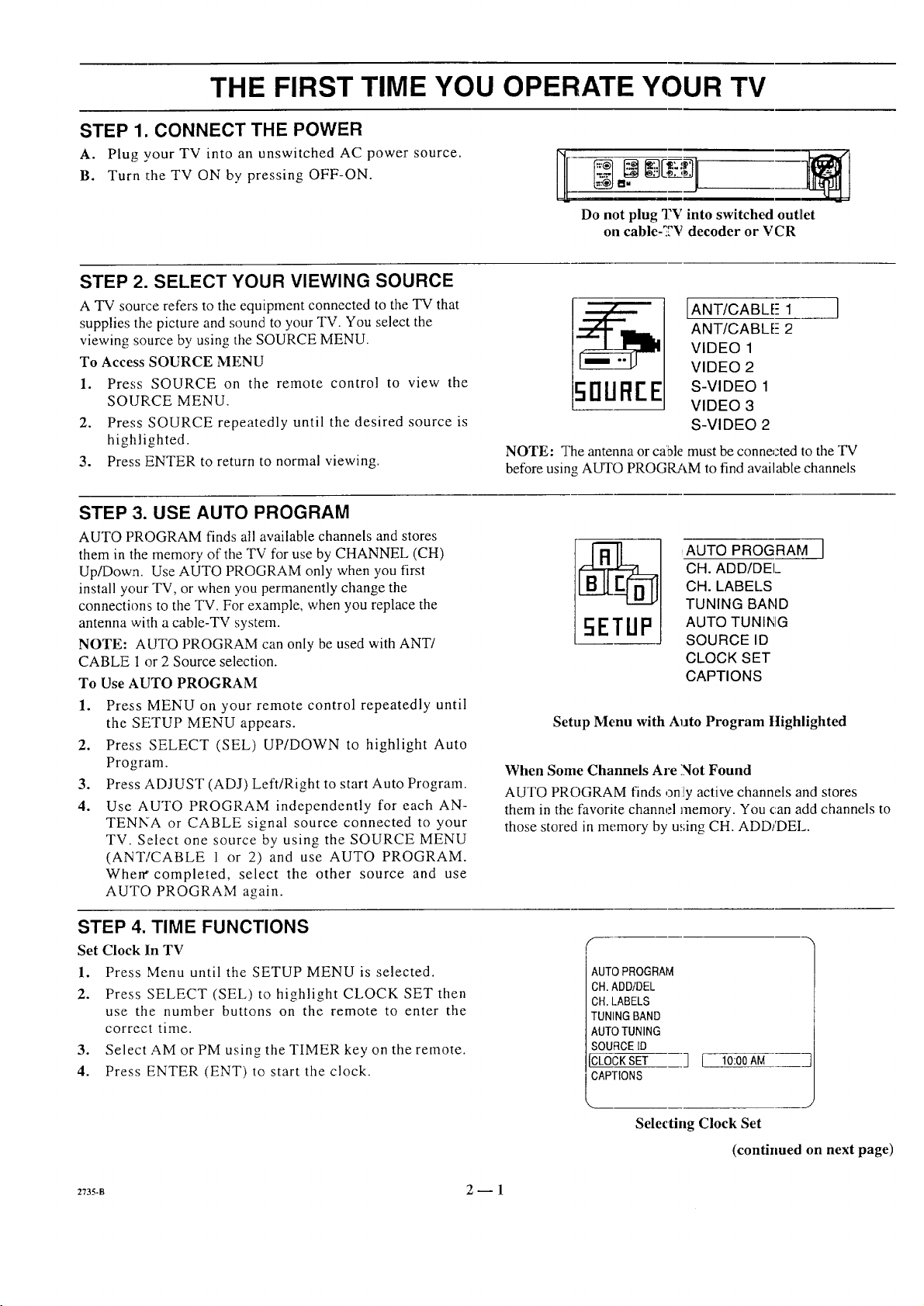
STEP 7. MAKE AUDIO CONNECTION TO STEREO AMPLIFIER
Using an External Amplifier with Speakers While the
TV's Speakers are OFF.
1. Place the SPEAKERS EXT/INT switch on the TV in
the INT position (TV's speakers are ON).
2. Turn the TV ON. Increase the volume level of the TV
until the sound just starts to distort (sound bad).
3. Place the SPEAKERS EXT!INT switch on the TV in
the EXT position (TV's speakers are OFF).
'4. Turn the external audio amplifier ON. Adjust the
volume level of the audio amplifier for the highest
level you will need for your listening pleasure.
5. Adjust the volume level of the TV for the normal
listening level as heard through the speakers of your
audio amplifier.
Using an External Amplifier with Speakers While the
TV's Speakers are ON.
1. Place the SPEAKERS EXT/INT switch on the TV in
the INT position (TV's speakers are ON).
2. Turn the TV ON. Increase the volume level of the TV
until the sound just starts to distort (sound bad).
3. Turn the external audio amplifier ON. Adjust the
volume level of the audio amplifier for the highest
level you will need for your listening pleasure.
4. Adjust the volume level of the TV for l:her_ormal listening
level as heard throu_;h the speakers of the TV.
NOTE: If the volume of the internal TV speakers is set too
low, you may hear undesirahle noises through the speakers
connected to your audio amplifier.
2735-0 1 --5
Page 10
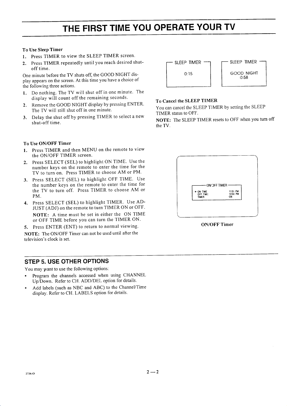
THE FIRST TIME YOU OPERATE YOUR TV
STEP 1. CONNECT THE POWER
A. Plug your TV into an unswitched AC power source.
B. Turn the TV ON by pressing OFF-ON.
STEP 2. SELECT YOUR VIEWING SOURCE
A TV source refers to the equipment connected to the TV that
supplies the picture and sound to your TV. You select the
viewing source by using the SOURCE MENU.
To Access SOURCE MENU
1. Press SOURCE on the remote control to view the
SOURCE MENU.
2. Press SOURCE repeatedly until the desired source is
highlighted.
3. Press ENTER to return to normal viewing.
STEP 3. USE AUTO PROGRAM
AUTO PROGRAM finds all available channels and stores
them in the memory of the TV for use by CHANNEL (CH)
Up/Down. Use AUTO PROGRAM only when you first
install your TV, or when you permanently change the
connections to the TV. For example, when you replace the
antenna with a cable-TV system.
NOTE: AUTO PROGRAM can only be used with ANT/
CABLE 1 or 2 Source selection.
To Use AUTO PROGRAM
1. Press MENU on your remote control repeatedly until
the SETUP MENU appears.
2. Press SELECT (SEL) UP/DOWN to highlight Auto
Program.
.
Press ADJUST (ADJ) Left/Right to start Auto Program.
4.
Use AUTO PROGRAM independently for each AN-
TENNA or CABLE signal source connected to your
TV. Select one source by using the SOURCE MENU
(ANT/CABLE 1 or 2) and use AUTO PROGRAM.
When" completed, select the other source and use
AUTO PROGRAM again.
Do not plug 'I?V into switched outlet
on cable-_2V decoder or VCR
IANT/CABLE- 1
ANT/CABLE- 2
VIDEO 1
VIDEO 2
50UREE
S-VIDEO 1
VIDEO 3
S-VIDEO 2
NOTE: The antenna or cable must be connected to the "IV
before using AUTO PROGRAM to find available channels
CH. ADD/DEI_
CH. LABELS
TUNING BAND
AUTO PROGRAM i
AUTO TUNING
SOURCE ID
CLOCK SET
CAPTIONS
Setup Menu with Auto Program Highlighted
When Some Channels Are Not Found
AUTO PROGRAM finds ,3ni!yactive channels and stores
them in the favorite channel memory. You can add channels to
those stored in memory by u_;ingCH. ADD/DEL.
STEP 4. TIME FUNCTIONS
Set Clock In TV
1. Press Menu until the SETUP MENU is selected.
2. Press SELECT (SEL) to highlight CLOCK SET then
use the number buttons on the remote to enter the
correct time.
3. Select AM or PM using the TIMER key on the remote.
4. Press ENTER (ENT) to start the clock.
2735-B 2-- 1
AUTOPROGRAM
CH.ADD/DEL
CH.LABELS
TUNINGBAND
AUTOTUNING
SOURCE[D
CLOCKSET
CAPTIONS
_m__ J
Selecting Clock Set
] [ 10:00AM
(continued on next page)
Page 11
THE FIRST TIME YOU OPERATE YOUR TV
To Use Sleep Timer
1. Press TIMER to view the SLEEP TIMER screen.
2. Press TIMER repeatedly until you reach desired shut-
offtime.
One minute before the TV shuts off, the GOOD NIGHT dis-
play appear,; on the screen. At this time you have a choice of
the following three actions.
1. Do nothing. The TV will shut off in one minute. The
display will count off the remaining seconds.
2. Remove the GOOD NIGHT display by pressing ENTER.
The TV will still shut off in one minute.
3. Delay the shut off by pressing TIMER to select a new
shut-off time.
To Use ON/OFF Timer
1. Press TIMER and then MENU on the remote to view
the ON/OFF TIMER screen.
2. Press SELECT(SEL) to highlight ON TIME. Use the
number keys on the remote to enter the time for the
TVtoturnon. Press TIMER to choose AM orPM.
3. Press SELECT (SEL) to highlight OFF TIME. Use
the number keys on the remote to enter the time for
the TV to turn off. Press TIMER to choose AM or
PM.
4. Press SELECT (SEL) to highlight TIMER. Use AD-
JUST (ADJ) on the remote to turn TIMER ON or OFF.
NOTE: A time must be set in either the ON TIME
or OFF TIME before you can turn the TIMER ON.
5. Press ENTER (ENT) to return to normal viewing.
NOTE: The ON/OFF Timer can not be used until after the
television's clock is set.
0:15
_ SLEEP TIMER --1
GOOD NIGHT
0:58
SLEEP TIMER -_
To Cancel the SLEEP TIMER
You can cancel the SLEEP TIMER by setting the SLEEP
TIMER status to OFF.
NOTE: The SLEEP TIMER resets to OFF when you turn off
the TV.
ON/3FF TIMER --
-_ ON TIME f1.'51 PW
OFF TIMI- 12:D0 PM
TIMER ON
ON/OFF Timer
STEP 5. USE OTHER OPTIONS
You may _vant to use the following options:
• Program the channels accessed when using CHANNEL
Up/Down. Refer to CH. ADDiDEL option for details.
• Add labels (such as NBC and ABC) to the Channel/Time
display'. Refer to CH. LABELS option for details.
2736-0 2 --2
Page 12
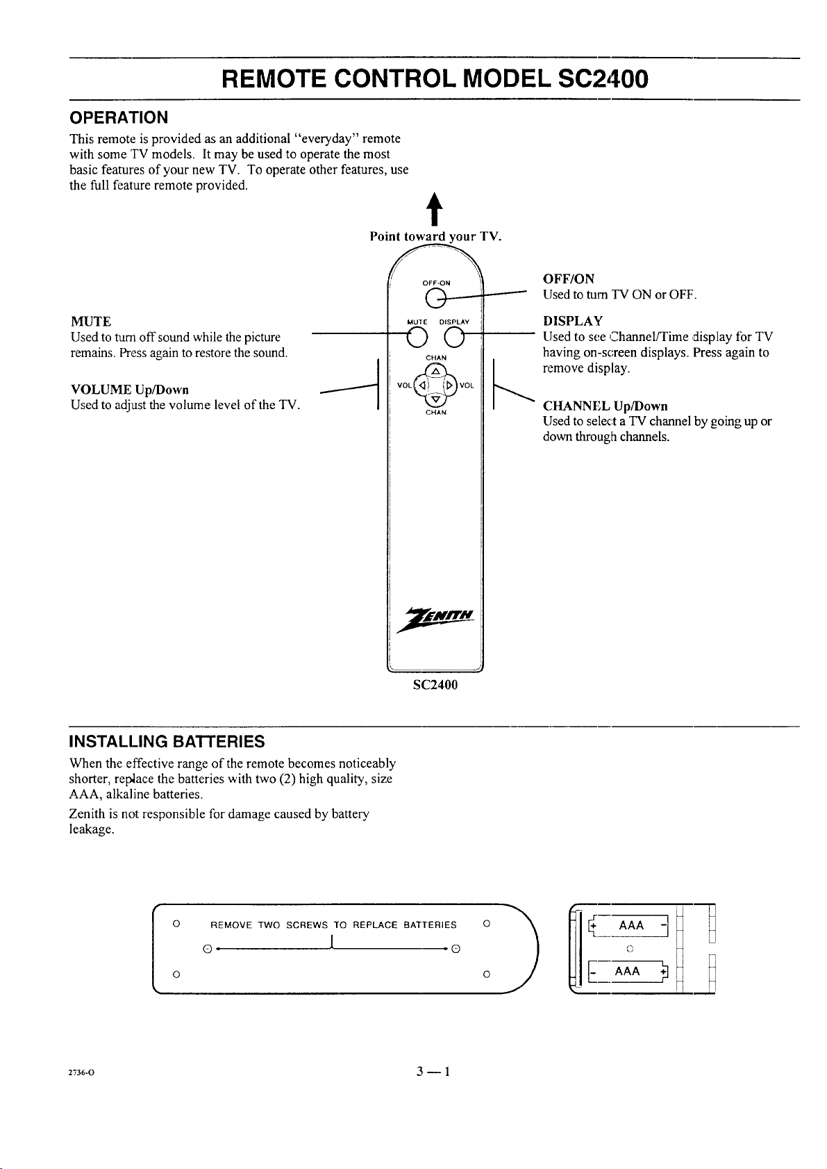
REMOTE CONTROL MODEL SC2400
OPERATION
This remote is provided as an additional "everyday" remote
with some TV models. It may be used to operate the most
basic features of your new TV. To operate other features, use
the full feature remote provided.
Point toward your TV.
t
OFF/ON
Used to turn TV ON or OFF.
MUTE
Used to turn off sound while the picture
remains. Press again to restore the sound.
VOLUME Up/Down
Used to adjust the volume level of the TV.
MUTE DISPLAY
O©
CHAN
VOL_VOL
CHAN
SC2400
DISPLAY
LIsedto see Channel/Time display for TV
having on-screen displays. Press again to
_ remove display.
CHANNEL Up/Down
Used to select aTV channel by going up or
down through channels.
INSTALLING BATTERIES
When the effective range of the remote becomes noticeably
shorter, replace the batteries with two (2) high quality, size
AAA, alkaline batteries.
Zenith is not responsible for damage caused by battery
leakage.
o
REMOVE TWO SCREWS TO REPLACE BATTERIES
o l o
o
2736-0 3-- 1
Page 13
REMOTE CONTROL MODEL MBR3420
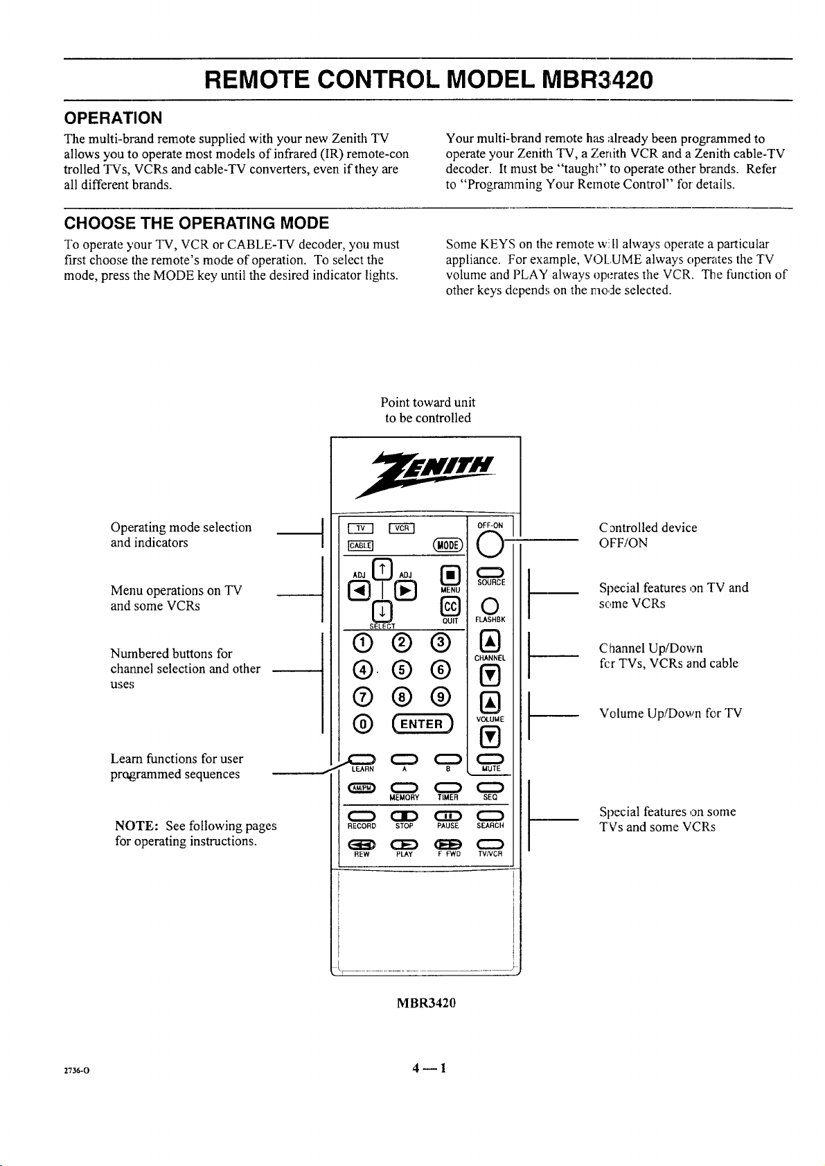
OPERATION
The multi-brand remote supplied with your new Zenith TV
allows you to operate most models of infrared (IR) remote-con
trolled TVs, VCRs and cable-TV converters, even if they are
all different brands.
CHOOSE THE OPERATING MODE
To operate your TV, VCR or CABLE-TV decoder, you must
first choose the remote's mode of operation. To select the
mode, press the MODE key until the desired indicator lights.
Point toward unit
to be controlled
Your multi-brand remote has already been programmed to
operate your Zenith TV, a Zenith VCR and a Zenith cable-TV
decoder. It must be "taught" to operate other brands. Refer
to "Programming Your Remote Control" for' details.
Some KEYS on the remote w:.I1always operate a particular
appliance. For example, VOLUME always operates the TV
volume and PLAY always operates the VCR. The function of
other keys depends on the mode selected.
Operating mode selection
and indicators
Menu operations on TV
and some VCRs
Numbered buttons for
channel selection and other
uses
Learn functions for user
programmed sequences
NOTE: See following pages
for operating instructions.
cram (NN
ADJ _ ADJ
SELECT
QUIT
®®®
®.®®
®®®
® )
LEARN A 8
_ C::) C:::::) C:::)
C:::_ CI::) CiD C::)
MEMORY TIMER SEQ
RECORD STOP PAUSE SEARCH
REW PLAY g FWD TVNCR
C_ntrolled device
OFF/ON
Special features on TV and
some VCRs
Channel Up/Down
fcr TVs, VCRs and cable
Volume Up/Down for TV
Special features on some
TVs and some VCRs
_r
MBR3420
2736-0 4 _ 1
Page 14
REMOTE CONTROL MODEL MBR3420
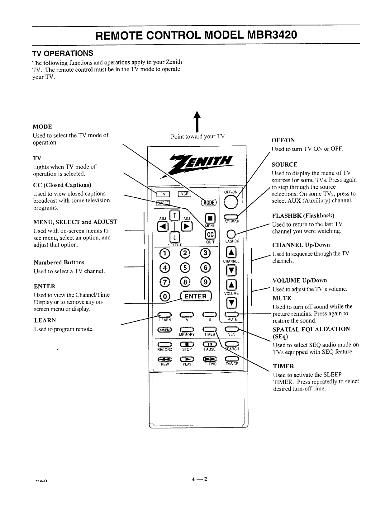
TV OPERATIONS
The following functions and operations apply to your Zenith
TV. The remote control must be in the TV mode to operate
your TV.
MODE
Used to select the TV mode of
operation.
TV
Lights when TV mode of
operation is selected.
CC (Closed Captions)
Used to view closed captions
broadcast with some television
programs.
MENU, SELECT and ADJUST
Used with on-screen menus to
see menu, select an option, and
adjust that option.
Numbered Buttons
Used to select a TV channel.
ENTER
Used to view the Channel/Time
Display or to remove any on-
screen menu or display.
LEARN
Used to progam remote.
t
Point toward your TV.
OFF-ON /
v
SOURCE
OI
SELECT
®®®
®®®
®®®
LEARN A B
RECORD STOP PAUSE _,,_RCH
FLASRBK
C EL
IAI
MLITE
OFF/ON
Used to turn TV ON!or OFF.
SOURCE
Used to display the menu of TV
sources for some TVs. Press again
t_ step through the source
selections. On some TVs, press to
select AUX (Auxiliary) channel.
FLASHBK (Flashback)
Used to return to the last TV
_
channel you were watching.
CHANNEL Up/Down
Used to sequence through the TV
channels.
VOLUME Up/Down
J_
Used to adjust the TV's volume.
lVIUTE
Used to turn off" sound while the
picture remains. Press again to
restore the sourLd.
SPATIAL EQUALIZATION
(SEq)
Used to select SEQ audio mode on
'FVs equipped with SEQ feature.
REW PLAY F FWD TV/VCR
I
2_36-o 4 _ 2
TIMER
Used to activate the SLEEP
TIMER. Press repeatedly to select
desired turn-off time.
Page 15
REMOTE CONTROL MODEL MBR3420
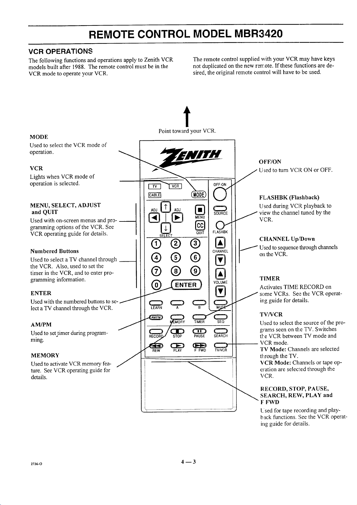
VCR OPERATIONS
The following functions and operations apply to Zenith VCR
models built after 1988. The remote control must be in the
VCR mode to operate your VCR.
The remote control supplied with your VCR may have keys
not duplicated on the new remote. If these functions are de-
sired, the original remote control will have to be used.
t
MODE
Used to select the VCR mode of
operation.
VCR
Lights when VCR mode of
operation is selected.
MENU, SELECT, ADJUST
and QUIT
Used with on-screen menus and pro-
gramming options of the VCR. See
VCR operating guide for details.
Numbered Buttons
Used to select a TV channel through
the VCR. Also, used to set the
timer in the VCR, and to enter pro-
gramming information.
ENTER
Used with the numbered buttons to se-
lect a "IV channel through the VCR.
A VPM J
Used to set.timer during program-
ming.
MEMORY
Used to activate VCR memory fea-
ture. See VCR operating guide for
details.
Point toward your VCR.
ADJ @ ADJ
SOURCE
oi
SELECT
QUIT FLASHBK
®®®
CHANNEL
®® ®
®®®
VOLUME
LEARN A ___
_ TIME. SEQ
,_ _ PAUSE SEARCH
REW PLAY F FWD TMNCR
OFF/ON
Used to turn VCR ON or OFF.
FLASHBK (Flashback)
Used during VCR playback to
j iew the channel tuned by the
VCR.
CHANNEL Up/Down
/ Used to sequence through channels
on theVCR.
TIMER
Activates TIME RECORD on
some VCRs. See the: VCR operat-
ing guide for details.
TV/VCR
Used to select the source of the pro-
grams seen on the TV. Switches
tt:e VCR between TV mode and
VCR mode.
TV Mode: Charmels are selected
ff¢ough the TV.
VCR Mode: Channels or tape op-
eration are selec_!ed through the
VCR.
2736-0 4 --3
RECORD, STOP, PAUSE,
SEARCH, REW, PLAY and
F FWD
l._sed for tape recording and play-
back functions. See the VCR operat-
ing guide for details.
Page 16

REMOTE CONTROL MODEL MBR3420
CABLE-TV OPERATIONS
The following fimctions and operations apply to a Zenith
cable-TV decoder. The remote control must be in the CABLE
mode to operate your cable-TV decoder.
The remote control supplied with your cable-TV decoder may
have keys not duplicated on _:henew remote. If these functions
are desired, the original remote control will haw; to be used.
t
MODE
Used to select the Cable mode of
operation.
CABLE
Lights when CABLE mode of
operation is selected.
MENU, SELECT, ADJUST
and QUIT
Functions depend on Cable-TV
system. See Cable-TV decoder
operating _guidefor details.
Numbered Buttons
Used to select channels through
Cable-TV decoder.
ENTER
Used with the numbered buttons to
select a TV channel through the
Cable-TV decoder.
Point toward your Cable-TV decoder.
OFF-ON
V
ADJ@ AD._
[_ MENU
SELECT
QUIT
SOUFtCE
0
FLASHBK
® ®®
® ®®
w
®® ®
ENTER )
C_ C_ C_
LEARN A B
_ c::) C:b (::D
MEMORY TIMER SEQ
IAI
VOLUME
IVl
J
MUTE
OFF/ON
Used to turn VCR ON or OFF.
SOURCE
" Selects "A" or "B" cable channels.
_._ CHANNEL Up/Down
"Used to sequence through channels
on the Cable-TV decoder.
RECORD STOP PAUSE SEARCH
REW PLAY F FWD TV/VCR
_T .... T
2736-o 4 _ 4
Page 17

REMOTE CONTROL MODEL MBR3,420
PREPARATION FOR USE
Batteries are provided with this remote, but you must install
them before using the remote.
INSTALLING BATTERIES
When the effective operating range of your remote becomes
noticeably shorter, replace the batteries with two high-quality,
alkaline, size AAA batteries.
Zenith is no!:responsible for damage caused by battery leak-
age.
After installing new batteries, the remote control "will set itself
to Zenith brand codes, as follows: TV=101, VCR=201 and
CABLE=301.
If you are going to operate equipment that uses different
codes, the remote must be rewogrammed for those codes.
273_-o 4 _ 5
Page 18

REMOTE CONTROL MODEL MBR3,420
PROGRAMMING BRAND CODES
Introduction
Before using your new remote control, it must be programmed
to recognize the brands of equipment it will be used to oper-
ate. If you are using a Zenith VHS VCR or a Zenith cable-TV
decoder, the remote has already been programmed for you.
Find the code that corresponds to each brand and type of
equipment you are going to operate. Refer to Tables 1, 2 and 3.
For example, if you were programming the remote for use
with a Zenith TV, you would look for "Zenith" in "Table 1",
and find code "101 ."
Write the brand codes for your equipment on the following
lines.
TV CODE:
CABLECODE:
VCRCODE:
1. Press MODE repeatedly to select the desired TV,
VCR or CABLE operating mode for the remote.
2. Press LEARN for about 5 seconds until the MODE
indicator lights for 'the selected TV, VCR or CABLE
mode of operation.
3. Enter the proper brand code number for 1:he equipment
to be controlled.
4. Press LEARN. All three mode indicators should light
briefly, then turn off to indicate the brand code has
been programmed.
5. If all three mode indicators fail tc, light briefly, an
error has occurred. Repeat Steps 1-4 to try again.
6. Repeat: steps 1-4 to program the remote for the other
equipment you are using.
NOTE: CABLE mode can be programmed to operate a sec-
ond TV or second VCR, if desired.
When batteries are removed: It will be necessary to reprogram
the proper VCR and cable.-T'v' decoder codes.
Operating Mode
Indicators
Numbered Buttons
Use to enter code number
for desired brand.
LEARN Button
I
ADJ [_ ADJ
SELECT
@®@
®®®
®®@
@ (E.TE.)
.CZ} (:::=D (:::_ (::_
LEARN A B MUTE
(:_) (:::::::) (::ZD (:::::::)
MEMORY TIMER SEQ
C:::_ OD C3_ (:Z:)
RECORD STOP PAUSE SEARCH
E_i_i) (:3ED (_Et_ (Z::)
REW pLAy F FWD TVNCR
QUIT
CD
SOURCE
O
FLASHBK
CHANNEl_
VOLUME
®
Operating MODE Selector
M
2v36-o 4--6
Page 19

REMOTE CONTROL MODEL MBR3420
TV, VCR AND CABLE-TV OPERATING CODES
Table 1. TV Codes by Brand
TV Brand TV Brand
Name Code Name Code
Admiral 116 Montgomery Ward 119
Admiral 121 Montgomery Ward 121
Akai 104 Montgomery Ward 130
Amark 103 NEC 104
AOC 104 NEC 119
Bell & Howell 121 Panasonic 106
Centurion 1t9 Panasonic 107
Coronado 103 Philco 103
Curtis Marines 116 Phitco 104
Curtis Mathes 119 Philco 112
Curtis Mathes 121 Philco 113
Daytron 119 Philips 112
Emerson 103 Phi[ips 113
Emerson 104 Pioneer 135
Emerson 123 Portland 103
Emerson 124 Quasar 106
Emerson 131 Quasar 107
Emerson 136 Realistic 105
Fisher 109 Realistic 123
Fisher 118 Realistic 124
General Electric 106 RCA 104
General Electric 107 RCA 116
General Electric 114 RCA 126
General Electric 116 Sampo 119
Goldstar 103 Samsung 103
Goldstar 104 Samsung 119
Goldstar 119 Samsung 134
Hitachi 102 Sanyo 108
Hitachi 103 Sanyo 109
Hitachi 129 Sanyo 118
JVC 125 Scott 119
JVC 132 Sears 103
J.C. Penney 104 Sears 108
J.C. Penney 110 Sears 109
J.C. Penney 114 Sears 110
J.C. Penney 117 Sears 111
J.C. Penney " 119 Sears 118
KMC 103 Sears 134
KTV 103 Sharp 103
KTV t04 Sharp 105
Lodgenet 121 Sharp 122
Logik 121 Sharp 133
LXI 133 Sharp 137
LXI 137 Sony 115
Magnavox 103 Sylvania 112
Magnavox, 112 Sylvania 113
Magnavox 113 Sylvania 117
Magnavox 119 Sylvania 119
Magnavox 127 Sylvania 127
Magnavox 128 Sylvania 128
Majestic 121 Tatung 106
Marantz 104 Teknika 103
Marantz 120 Teknika 112
Memorex 121 Teknika 121
MGA/Mitsubishi 104 Te"knika 124
MGA!Mitsubishi 119 Telerent 103
MGAfMitsubishi 120 Telerent 121
MGA/Mitsubishi 130 Toshiba 110
Montgomery Ward 103 Toshiba I11
Montgomery Ward 104 Toshiba 134
MontgomeD'Ward 105 Yorx 119
Montgomery Ward 113 Zenith 101
Montgomery Ward 114
Table 2. VCR Codes by Brand
VCR Brand VCR Brand
Name Code Name (-;ode
Akai 223 Pentax 215
Audio Dynamics 202 Philco 214
Audio Dynamics 218 Philips 214
Broksonic 221 Philips 227
Canon 214 Pioneer 210
Citizen 209 Pioneer 215
Craig 212 Pioneer Laser Dtsk 228
Curtis Mathes 214 Quasar 214
Curtis Mathes 216 RCA 215
DBX 202 RCA 216
DBX 218 RCA 220
Emerson 203 RCA 227
Emerson 221 Realistic 206
Emerson 223 Realistic 208
Emerson 226 Realistic 212
Emerson 233 Realistic 214
Emerson 2135 Realistic 231
Fisher 211 Samsung 22(I
Fisher 212 Samsung 230
Fisher 213 Sanyo 206
Funai 231 Sanyo 212
General Electric 214 Scott 204
General Electric 216 Scott 205
General Electric 220 Scott 233
Goldstar 209 Sears 206
Hitachi 215 Sears 209
Instant Replay 214 Sears 211
Instant Replay 227 Sears 212
JVC 202 Sears 215
JVC 225 Sharp 208
J.C. Penney 214 Sony VHS 232
J.C. Penney 218 Sony Video 8 217
J.C. Penney 227 Sylvania 207
Kenwood 202 Sylvania 214
Magnavox 207 Sylvania 227
Magnavox 214 Symphonic 231
Marantz 207 Tashiko 209
Marantz 218 Tatung 202
Maria 209 Teac 202
Memorex 212 Teac 231
Memorex 214 Teknika 234
Memorex 231 Toshiba 205
MGA/Mitsubishi 204 Toshiba 215
MGA/Mitsubishi 222 Vector Research 204
Montgomery Ward 208 Vector Research 218
Montgomery Ward 214 Yanraha 202
Montgomery Ward 219 Yamaha 218
NEC 202 Zenith VHS 201
NEC 218 Zenith VHS 225
Panasonic 214 Zenith VHS 229
Table 3. Cable Decoder Codes by
Brand
Cable Decoder C able Decoder
Brand Name Code Brand Name Code
Drake Satdlite 312 Pioneer 315
Drake Satellite 330 Regency 329
Gemini 305 Samsung 335
Gemini 331 Scientific Atlanta 316
General Irstrument 305 Scientific Atlanta 323
General lrstrumcnt 306 Szientific Atlanta 336
1tamlirt 302 Sprucer
ltamlin 303 (P_asonic) 313
Jerrold 304 Standard
Jerrold 307 Components 335
Jerrold 308 STS Satellite 324
Jerrold 309 "l-elecaption 4000 325
Jerrold 310 Tocom 317
Kale Vision 335 "I'ocomVIP 318
Macom 3 I4 Toshiba 322
Macora 321 Toshiha Satellite 319
Macora Satellite 322 Zenith 301
Magnavo_ 334 Zenifft 322
NSC 335 Zenith AV3000 327
Oak 311 Zenith Satellite 312
Oak 332 Zenith Satellite 330
Panasonic 313 7enith Satellite 328
Panasonic 320 Zenith Laser Disk 326
Paragon tZcnith) 333
m+-o 4 --7
Page 20

REMOTE CONTROL MODEL MBR3430
OPERATION
The multi-brand remote supplied with your new Zenith TV
allows you to operate most models of infrared (IR)
remote-controlled TVs, VCRs and cable-TV converters, even
if they are all different brands.
CHOOSE THE OPERATING MODE
To operate your TV, VCR, CABLE-TV decoder, or an AUX
(auxilia_) device, you must first choose the remote's mode of
operation. To select the mode, press the MODE key until the
desired indicator lights.
Point toward unit
to be controlled
Your multi-brand remote Eas already been programmed to
operate yore"Zenith TV, a Zenith VCR and a Zenith cable-TV
decoder. It :must t)e "taught" to operate other brands. Refer
to "Programming Your Remote Control" fc,rdetails.
Some KEYS on the remote will always operate a particular
appliance. For example, VOLUME always operates the TV
volume and PLAY always operates the VCR. The function of
other keys depends on the mode selected.
Operating mode selection
and indicators
Menu operations on TV
and some VCRs
Numbered buttons for
channel selection and other
uses
Learn functions for user
programmed sequences
NOTE: See following pages
for operating instructions.
OFF-ON
(Ng)
ADJ [_ ADJ
SELECT
QUIT
O
C2D
SOURCE
O
FLASHBK
®®®
CHANNEL
®®®
®®®
VOLUME
LEARN PIP FREEZE
(:Z_) _ (:Z) CZ:)
(:Z) aD CiD (:Z:)
RECORD STOP PAUSE SEARCH
ei_D (:::E) (lEE) C:::D
SWAP TIMER SEQ
REW PLAY F FWD TVNCR
&lUTE
!
t-
t-
Controlled device
OFF/ON
Special features on TV and
some VCRs
Channel Up/Down
fi)r TVs, VCRs and cable
Volume Up/Down fi)r TV
Special features on some
TVs and some VCP,cs
MBR3430
2w6-o 5 -- 1
Page 21

REMOTE CONTROL MODEL MBR3430
"IV OPERATIONS
The following functions and operations apply to your Zenith
"IV. The remote control must be in the TV mode to operate
your TV.
MODE
Used to select the TV mode of
operation.
'rV
Lights when TV mode of
operation is selected.
CC (Closed Captions)
Used to view closed captions
broadcast with some television
programs.
MENU, SEI,ECT and ADJUST
Used with on-screen menus to
see menu, select an option, and
adjust that option.
Numbered Buttons
Used to select a TV channel.
ENTER
Used to view the Channel/Time
Display or to remove any on-
screen menu ,ordisplay.
LEARN
Used to program remote.
PIP
Used to activate
Picture-In-Picture inset.
SWAP
Used to swap picture in PIP inset
with the main television picture.
t
Point toward your TV.
SELECT
® ®®
®®®
®®®
P,P
STOP PAUSE
REW PLAY F FWD TVNC
QUIT
(3D
OFF/ON
Used to _rn TV ON or OFF.
SOURCE
Use5 to display the menu of TV
sources for some TVs. Pressagain
slep through the source
selections. On some TVs, press to
select AUX (Auxiliary) channel.
FLASHBK (Flashback)
Used to return to the last TV
chalmel you were watching.
CHANNEL Up/Down
LIsed to sequence through the TV
(_mmels.
VOLUME Up/De,wn
Used to adjust the TV's "volume.
MUTE
l.Js_:d to turn off sound while the
picture remains. Press ;again to
restore the sound.
SPATIAL EQUALIZATION
(SEq)
Used to select SEQ audio mode on
TVs equipped with SEQ feature.
FREEZE
Used to freeze the motion of the
picture on the PIP inset
!
I
TIMER
Used to activate the SLEEP
TIMER. Press repeatedly to select
desired turn-off time.
z736-o 5_2
Page 22

REMOTE CONTROL MODEL MBR3430
VCR OPERATIONS
The following functions and operations apply to Zenith VCR
models built after 1988. The remote control must be in the
VCR mode to operate your VCR.
The remote control supplied with your VCR may have keys
not duplicated on the new remote. If these functions are
desired, the original remote control will have to be used.
t
MODE
Used to select the VCR mode of
operation.
VCR
Lights when VCR mode of
operation is selected.
MENU, SELECT, ADJUST
and QUIT
Used with on-screen menus and
programming options of the VCR.
See VCR operating guide for details.
Numbered Buttons
Used to select a TV channel through
the VCR. Also, used to set the
timer in the VCR, and to enter
programming information.
ENTER
Used with the numbered buttons to
select a "l'v"channel through the VCR.
AM/PM
Used to sel. timer during
programming.
Point toward your VCR.
OFF/ON
"Used to turn VCR O,Nor OFF.
)FF-ON
AO_(_ ADJ _)
N" "u
SELECT
QUIT
(!)@@
® ®®
,U
;OURCE
O1
F.ASHBK
CdANNEL
/' Used to sequence throughchannels
i CHANNEL Up/Down
FLASHBK (Flashback)
Used during VCR playback to
" iew the channel tuned by the
VCR.
on the VCR.
®®®
\ OLUME
_(ENTER )
J
LEARN PIP FREEZE
SWAP TIMER
RECORD STOP PAUSE SEARCH
aD (:3D CC)
REW PLAY F FWD TMNCR
222)
SEQ
TIMER
Activates TIME RECORD on
some VCRs. See the VCR
o:3erating guide for details.
TV/VCR
Used to select the source of the
programs seen on the TV. Switches
the VCR between TV mode and
VCR mode.
TV Mode: Channels are selected
tl:rough the TV.
VCR Mode: Channels or tape
operation are selected through the
VCR.
2736-0 5 -- 3
RECORD, STOP, PAUSE,
SEARCH, REW, PLAY and
F FWD
Used for tape record:ing and
playback functions. 'gee the VCR
operating guide :Fordetails.
Page 23

REMOTE CONTROL MODEL MBR3430
CABLE-TV OPERATIONS
The following functions and operations apply to a Zenith
cable-TV decoder. The remote control must be in the CABLE
mode to operate your cable-TV decoder.
The remote control supplied with your cable.-TV decoder may
have keys not duplicated on the new remote. If these functions
are desired, the original remole control will have to be used.
t
MODE
Used to select the Cable mode of
operation.
CABLE
Lights when CABLE mode of
operation is selected.
MENU, SELECT, ADJUST
and QUIT
Functions depend on Cable-TV
system. See Cable-TV decoder
operating guide for details.
Numbered Buttons
Used to select channels through
Cable-TV decoder.
ENTER
Used with the numbered buttons to
select a TV channel through the
Cable-TV decoder.
Point toward your Cable-TV decoder.
OFF/ON
j Used to turn VCR ON or OFF.
OFF-ON
SOURCE
AOJ[_ AOJ [_
SELECT
(!)®®
®0®
0
QUIT
SOURCE
O
FLASHBK
IAI
CHANNEL
IVI
__s CHANNEL Up/Down
Scqects "A" or "B" cable channels.
Used to sequence through channels
on the Cable-TV deco,-ler.
® ®®
VOLUME
IVI
/
LEARN PIP FREEZE
SWAP TIMER SEQ
C=_ aD ¢:3iZ_ _
RECORD STOP PAUSE SEARCH
(_ aE) dEE_ CZ2)
REW Pk_ F FWD _NCR
cZ_
MUTE
2736-o 5 -- 4
Page 24

REMOTE CONTROL MODEL MBR3430
PREPARATION FOR USE
Batteries are provided with this remote, but you must install
them before using the remote.
INSTALLING BATTERIES
When the effective operating range of your remote becomes
noticeably shorter, replace the batteries with two high-quality,
alkaline, size AAA batteries.
Zenith is not responsible for damage caused by battery
leakage.
After installing new batteries, the remote control will set itself
to Zenith brand codes, as follows: TV=101, VCR=201 and
CABLE=301.
If you are going to operate equipment that uses different
codes, the remote must be reprogrammed for those codes.
Step 1. Step 2.
Step 3.
2736-o 5 -- 5
Page 25

REMOTE CONTROL MODEL MBR3430
PROGRAMMING BRAND CODES
Introduction
Before using your new remote control, it must be programmed
to recognize the brands of equipment it will be used to
operate. If you are using a Zenith VHS VCR or a Zenith
cable-TV decoder, the remote has already been programmed
for you.
Find the code that corresponds to each brand and type of
equipment you are going to operate. Refer to Tables 1, 2 and 3.
For example, if you were programming the remote for use
with a Zenith TV, you would look for "Zenith" in "Table 1",
and find code "101 ."
Write the brand codes for your equipment on the following
lines.
TV CODE:
CABLE CODE:
VCR CODE:
1. Press MODE repeatedly to select the desired TV,
VCR or CABLE operating mode for the remote.
2, Press I,EARN for about 5 seconds until the MODE
indicator lights for the selected TV, VCR or CABLE
mode of operation.
3. Enter the proper brand code number for the equipment
to be controlled.
4. Press LEARN. All three mode indicators should light
briefly, then turn off to indicate the brand code has
been programmed.
5. If all three mode indicators fail to light briefly, an
error has occurred. Repeat Steps 1-4 to try again.
6. Repeat steps 1-4 to piogram the remote for the other
equipment you are using.
NOTE: CABLE mode c_a be programmed to operate a
second TV or second VCR, if desired.
When batteries are removed: It will be necess_y to reprogram
the proper VCR ;rodcable-TV decoder codes.
Operating Mode
Indicators
Numbered Buttons
Use to enter code number
for desired brand.
LEARN Button
I
ADJ _ ADJ
SELECT
®®®
®®®
O@(9
@ CXD CD
I:N_ _:1 CZ_ CSD
C:_ CID C3D C::)
RECORD STOP PAUSE SEARCH
(;3i_ CED (E_E_ CXD
REW PLAY F I_D TVAtCR
PiP FREEZE
SWAP TIMER SEQ
Operating MODE Selector
OFF-ON
QUIT
2736-o 5_6
Page 26

REMOTE CONTROL MODEL MBR3430
TV, VCR AND CABLE-TV OPERATING CODES
Table 1. TV Codes by Brand
"IV Brand TV Brand
Name Code Name Code
Admiral 116 Montgomery Ward 119
Admiral 121 Montgomery Ward 121
Akai 104 Montgomery Ward 130
Amark 103 NEC 104
AOC 104 NEC 119
Bell & Howell 121 Panasonic 106
Centurion 119 Panasonic 107
Coronado 103 Philco 103
Curtis Mathes 116 Philco 104
Curtis Mathes 119 Philco 112
Curtis Mathes 121 Philco 113
Da)_on 119 Philips 112
Emerson 103 Philips 113
Emerson 104 Pioneer 135
Emerson 123 Portland 103
Emerson 124 Quasar 106
Emerson 131 Quasar 107
Emerson 136 Realistic 105
Fisher 109 Realistic 123
Fisher 118 Realistic 124
General Electric 106 RCA 104
General Electric 107 RCA 116
General Electric 114 RCA 126
General r'lectric 116 Sampo 119
Goldstar I03 Samsung 103
Goldstar 104 Samsung 119
Goldstar 119 Samsung 134
Hitachi 102 Sanyo 108
Hitachi 103 Sanyo 109
Hitachi 129 Sanyo 118
JVC 125 Scott 119
JVC 132 Sears 103
J.C. Penney 104 Sears I08
J.C. Penney 110 Sears 109
J.C. Penney 114 Sears 110
J.C. Penney 117 Sears -111
J.C. Penney 119 Sears 118
KMC 103 Sears 134
KTV 103 Sharp 103
KTV 104 Sharp 105
Lodgenet 121 Sharp 122
Logik 121 Sharp 133
LXI 133 Sharp 137
LXI 137 Sony 115
Magnavox 103 Sylvania 112
Magnavox° !12 Sylvania 113
Magnavox 113 Sylvania 117
Magnavox 119 Sylvania 119
Magnavox 127 Sylvania 127
Magnavox 128 Sylvania 128
Majestic 121 Tatung 106
Marantz 104 Teknika 103
Marantz 120 Teknika 112
Memorex 121 Teknika 121
MGA/Mitsubishi 104 Teknika 124
MGA!Mitsubishi 119 Telerent 103
MGAfMitsubishi 120 Telerent 12l
MGAfMitsubishi 130 Toshiba 110
Montgomery Ward 103 Toshiba lll
Montgomery Ward 104 Toshiba 134
Montgomery Ward 105 Yorx 119
Montgomery Ward 113 Zenith 10l
Montgomery Ward 114
Table 2. VCR Codes by Brand
VCR Brand VCR Brand
Name Code Name Code
Akai 223 Pent_Lx 2_ 5
Audio Dynamics 1202 Philco 2!4
Audio Dynamics :218 Philips 24
Broksonic :221 Philips 2:!7
Canon :214 Pioneer 2t 0
Citizen 1209 Pioneer 215
Craig 2t2 Pioneer Laser Disk 228
Curtis Mathes 214 Quasar 214
Curtis Mathes 216 RCA 215
DBX 202 RCA 216
DBX 218 RCA 220
Emerson 203 RCA 227
Emerson 221 Realistic 206
Emerson 223 Realistic 21)8
Emerson 226 Realistic 212
Emerson 233 Realistic 214
Emerson 235 Realistic 231
Fisher 211 Samsung 220
Fisher 212 Samsung 230
Fisher 213 Sanyo 206
Funai 231 Sanyo 212
General Electric 214 Scott 204
General Electric 216 Scott 205
General Electric 220 Scott 2.33
Goldstar 209 Sears 206
Hitachi 215 Sears 209
Instant Replay 214 Sears 211
Instant Replay 227 Sears 212
JVC 202 Sears 215
JVC 225 Sharp 208
J.C. Penney 214 Sony VHS 232
J.C. Penney 218 Sony Video 8 217
J.C. Penney 227 Sylvania 207
Kenwood 202 Sylvania 214
Magnavox 207 Sylvania 227
Magnavox 214 Symphonic 231
Marantz 207 Tashiko 209
vlarantz 218 Tatung 232
Vlarta 209 Teac 202
Memorex 212 Teac 231
Memorex 214 Teknika 234
Memorex 231 Toshiba 2,35
MGA/Mitsubishi 204 Toshiba 215
MGA!Mitsubishi 222 Vector Research 204
Montgomery Ward 208 Vector Research 218
Montgomery Ward 214 Yamaha 232
Montgomery Ward 219 Yamaha 218
NEC 202 Zenith VHS 201
NEC 218 Zenith VItS 225
Panasonic 214 Zenith VHS 229
Ta ble 3. Cable Decoder Codes by
Cable Decoder Cablte Decoder
Brand Name Code Brand Name Code
Drake Satellite 312 Pioneer 315
Drake Satellite 330 Regency 329
Gemini 305 Samsung 335
Gemini 331 Scientific Atlanta 316
General Instrument 305 Scientific Atlanta 323
General Instrument 306 Scientific Atlanta 336
[tamtin 302 Sprucer
llamtin 303 (Panasonic) 313
Jerrold 304 Standard
Jerrold 307 Components 335
Jerrold 308 STS Satellite 324
Jerrold 309 Telezaption 4000 325
Jerrold 310 Tocom 317
Kale Vidon 335 Tocom VIP 318
Macom 314 Toshiba 322
Macom 321 Toshiba Satellite 319
Macom Satellite 322 Zenith 301
Magnavox 334 Zenith 322
NSC 335 Zenith AV3000 327
Oak 311 Zenith Satellite 312
Oak 332 Zenith Satellite 330
Panasoric 313 Zenith Satellite 328
Panasoric 320 Zenith Laser Disk 326
Paras,on (Zenith) 333
Brand
2736-0 5 -- '7
Page 27

QUICK REFERENCE TO ON-SCREEN MENUS
AVAILABLE MENUS
Your TV is icon and menu operated. That is, an icon is se-
lected at the top of the TV screen and a menu of adjustment
options appears.
\
5DUREE SETUP
IAUTO PROGRAM
CH. ADD/DEL
CH. LABELS
TUNING BAND
AUTO TUNING
SOURCE ID
CLOCK SET
CAPTIONS
SUMMARY OF MENU ITEMS
[ANT/CABLE 1
ANT/CABLE 2
VIDEO 1
VIDEO 2
,50UREE
* Some models only.
S-VIDEO 1
VIDEO 3 -_
S-VIDEO 2
AUDIO UIOED PIP
\
Unhighlighted
Highlighted
Menu for highlighted icon appears
at left of TV screen.
ANT/CABLE 1 or 2 : Either of these source, s may be used
for input from an antenna or a cable-TV line.
VIDEO 1 or 2 : Either of these sources may be used for input
from a VCR.
S-VIDEO 1 : Use this source ifa Super-VHS VCR is con-
nected to your TV.
VIDEO :3: Use this source if a camcorder is connected to
your TV.
S-VIDEO 2 : Use this source ifa second Super-VHS VCR is
connected to your TV.
CH. ADD/DEL
CH. LABELS
TUNING BAND
IAUTO PROGRAM
AUTO TUNING
SOURCE ID
CLOCK SET
CAPTIONS
AUTO PROGRAM: Finds all available channels and stores
them in the memou of the TV for use with CHANNEL
Up!Down.
2736-o 6 _ 1
CH. ADD/DEL: Changes the list of active channels stored in
memory, so that only your favorite channels are selected when
using CHANNEL Up/Down.
CH. LABELS: Adds a channel label or name to the
channel/time display. For example, ABC may appear when
this network channel is tuned.
TUNING BAND: Determines the operation of the channel se-
lector inside the TV.
AUTO TUNING: Let,; your TV compensate for variations in
broadcast and cable-TV fi'equencies.
SOURCE ID: Lets yau assign a relevant name to each input
source.
CLOCK SET: Sets the TV's internal clock.
CAPTIONS: Displays closed captions (CC) or informational
text when available.
Page 28

QUICK REFERENCE TO ON-SCREEN MENUS
SUMMARY OF MENU ITEMS
IBASS
TREBLE
BALANCE
AUDIO
AUDIO
SEQ
SURROUND
BASS: Adjusts the BASS (low-fi-equency) level.
TREBLE: Adjusts the TREBLE (high-frequency) level.
BALANCE: Adjusts the BALANCE of sound between the
left and right speakers for stereophonic prognuns.
AUDIO MODE: Allows for receiving a Second Audio Pro-
gram (SAP), such as a program broadcast witi_ two audio por-
tions (typically two languages), or lets you select :stereophonic
(STEREO) or monaural (MONO) speaker operation.
SEQ: Turns on an enhanced stereo mode.
SURROUND: Adjusts Surround Sound vokLme when used
with separate]Ly supplied Smro and Sound speakers.
UIDED
PIP
* Some models only.
ICONTRAST
BRIGHTNESS
COLOR
TINT
SHARPNESS
COLOR TEMP
VIDEO FILTER
AUTO FLESH
PICTURE PREF
ICH. GUIDE
CH. REVIEW
PIP SOURCE
PIP COLOR
PIP TINT
PIP SIZE
CONTRAST: Adjusts the overall contrast and color level of
the picture.
BRIGHTNESS: Adjusts the I:,rightuess level of black areas in
the picture.
COLOR: Adjusts the intensity of the colors in the picture.
TINT: Adjusts the color of the flesh tones.
SHARPNESS: Adjusts the clarity of the edges of objects for the
clearest possible picture.
COLOR TEMP: Changes the "color temperature" or picture
white balance, between cooler natural whites and warmer (red)
colors.
VIDEO FILTER: Reduces video "noise" or interference in
dark picture areas resulting in clearer overall pictures.
AUTO FLESH: Automatically maintains natural skin tones
under changing scene and video source condition.,;.
PICTURE PREF: Lets you decide if you want to use your
own CUSTOM video settings, the factory PRESET video set-
tings, or the THEATER video settings for optimum viewing in
low-light conditions.
CH. GUIDE:: Provides a visual review of all channels in the
channel scan memory for the currently selected ANT!
CABLE source.
CH. REVIEW: Provides a visual review of the last three (3)
channels tuned on the TV.
PIP SOURCE: Lets you select the equipment that supplies
the picture to the PIP inset.
PIP COLOR: Adjusts the intensity of the colors in the PIP in-
set.
PIP TINT: Adjusts the color of the flesh tones.
PIP SIZE: Lets you choose between seeing a larger or
smaller PIP inset.
273_-o 6 -- 2
Page 29

QUICK REFERENCE TO ON-SCREEN MENUS
MENU OPERATION EXAMPLE
Press MENU repeatedly until the desired icon is highlighted
and its menu is showing. This example shows choosing the
SETUP MENU.
MENU
Press SELECT (SEL) Up/Down repeatedly until the desired
option/feature is highlighted. This example shows choosing
TUNING BAND.
T
_UTOPROGRA_Vt
ell. ADD/DEL
CH. LABELS
TUNINGBAND
AUTOTUNING
SOURCE ID
CLOCK SET
CAPTIONS
[AUTO PROGRAM
CH. ADD/DEL
CH. LABELS
TUNING BAND
AUTO TUNING
SOURCE ID
CLOCK SET
CAPTIONS
] [ CABLE-CATV
___.J
Press ADJUST (ADJ) Left/Right to adjust the option. This ex-
ample shows the choices you have for TUNING BAND.
ADJ. ADJ.
Press ENTER (ENT) or wait a few seconds and the TV will re-
turn automatically to normal operation.
Tuning Ban,t options are:
_AUTOPROGRAM
ICH. ADO/D('L
ICH. LABELS
1[ CABLE-CAW
IAUTO TUNING
SOURCE ID
CAPTIONS
CLOCK SET
>
ROADCAST ]
ABLE-CATV ]
ABLE-HRC ['-]
ABLE-ICC _] ]
i
2736-0 6--3
Page 30

SOURCE MENU
5FIUREE
:SOURCE SELECTION
Purpose
The viewing "source" refers to the equipment that supplies
the picture and sound to your TV. You select the viewing
:source by using the SOURCE MENU.
To Access the SOURCE MENU
1. Press SOURCE on the remote control to view the Menu
icons with SOURCE already selected and its menu show-
ing.
2. Press SOURCE repeatedly until the source you want is
highlighted.
3. Press ENTER to return to normal viewing.
[ANT/CABLE 1
ANT/CABLE 2
VIDEO 1
VIDEO 2
i
S-VIDEO 1
VIDEO 3 _-
S-VIDEO 2 _-
Source Menu
Some models ordy
CH 2
10:56
Channel/Time Display
For Antenna or Cable
Source
VIDEO l
10:56
I 1
J
Channel/Time Display
For Video or S-Video
Source
:SOURCE IDENTIFICATION
YELLOW WHITE
LE_rT/ RIGHT ]
AUDIO INPUT VIDEO INPUT J
Auxiliary A/V Jacks
Selecting VIDEO 3 : Routes the auxiliary video source (such
as a camcorder or VCR) to the TV for viewing. The video
source must be connected to the corresponding VIDEO 3
_iacks.
Selecting S-VIDEO 2: Routes the auxiliary Super-VHS VCR
source to the TV for viewing. The Super-VHS VCR must be
connected to the corresponding S-VIDEO 2 jacks.
BLUE RED
MAGENTA
[__
Connection Center on Back of TV
Selecting ANT/CABLE 1 or 2 : Routes the ANTENNA or
cable-TV source to the TV for viewing. You see program ma-
terial from whichever signal source is connected to the
ANT/CABLE 1or 2 jack.
Selecting VIDEO 1 or 2 : Routes the video source (such as a
VCR or a Video Disc player) to the TV for viewing. The
video source must be connected to the corresponding VIDEO
1/2jacks.
Selecting S-VIDEO 1 : Routes the auxiliary Super-VHS
VCR Source to the TV for viewing. The Super-VHS VCR
must be connected to the con'esponding input jacks.
:m6-o 7 -- 1
Page 31

To Access SETUP Menu
Refer to the "Using On-Screen
Menus" section for details.
Before Using SETUP Menu
Connect arid turn ON all external
equipment, such as cable "IN decoder,
VCR, etc. before using any item on
the SETUP Menu.
SETUP MENU
IAUTO PROGRAM
CH. ADD/DEL
CH. LABELS
TUNING BAND
AUTO TUNING
SOURCE ID
CLOCK SET
CAPTIONS
ISOURCE ID
CLOCK SET
CAPTIONS
5E,TUPI
Main Setup Menu
AUTO PROGRAM
Purpose
Finds all available channels and stores them in the memory of
the TV for use by CHANNEL (CH) Up/Down.
Use AUTO PROGRAM only when you first install your TV,
or when you permanently change the connections to the TV.
For example, when you replace the antenna with a cable-TV
system.
NOTE: AUTO PROGRAM can only be used with ANT/
CABLE 1 or 2 Source selection.
To Use AUTO PROGRAM
1. Press ADJUST (ADJ) Left/Right to start Auto Pro-
gram.
2. Use AUTO PROGRAM independently for each AN-
TENNA or CABLE signal source connected to your
TV. Select one source by using the SOURCE MENU
(ANT/CABLE 1 or 2) and use AUTO PROGRAM.
When completed, select the other source and use
AUTO PROGRAM again.
CH. (Channel) ADD/DEL
Purpose
Lets you add channels to and remove channels from the chan-
nel scan. In this way you can customize the channels that are
accessed through CHANNEL (CH) Up!Down.
NOTE: CH. ADD/DEL can only be used with ANT/CABLE
1 or 2 S_)urce selection.
To Add a Channel to Scan Sequence
1. Press ADJUST (ADJ) Left/Right to view the channel
add/delete screen.
2. Use the number buttons on the remote to enter the
channel or use ADJUST (ADJ) Left/Right and SE-
LECT Up/Down to move the highlight to the channel
you wish to add.
3. Add the channel by pressing SOURCE until the dis-
play shows ADDED.
Setup Menu for Video
and S-Video Sources
AUTOPROGRAM
CH.ADD/DEL
CH.LABELS
TUNINGBAN[)
AUTOTUNING
SOURCEID
CLOCKSET
CAPTIONS
,.___ J
Selecting Auto Program
1 I START
When Some Channels Are Not Found
AUTO PROGRAM finds only active channels and stores
them in the faw)rite channel memory. You can addchannels to
those stored in memory by using CH. ADD!DEL.
_UTOPROGRAM
;H.ADD/DEL j [
CH. LABEL._
TUNING BAND
AUTO TUNING
SOURCE ID
CLOCK SET
CAPTIONS
Selecting Ch. Add/Del
CH 15 AriD
To Delete a Channel from Scan Sequence
1. Press ADJUST (ADJ) Left/Right to view the channel
add!delete screerL.
2. Use the number buttons on the remote to enter the
channel or use ADJUST (ADJ) Left/Right and SE-
LECT Up/Down to move the highlight to the channel
you wish to delete.
3. Delete the channel by pressing SOURCE until the
display shows DELETED.
(continued on next page)
2_s6-o 8 _ 1
Page 32

SETUP MENU
m
1
Available channels for currently
selected source.
Available channels are:
BROADCAST Band --
VHF 2 to 13, UHF 14 to 69
CATV, HRC and ICC Bands --
1 to 125
Use SELECT Down to move
highlight to ihigher numbers.
N
CH. (Channel) LABELS
Purpose
Assigns anetwork label or "name" to the selected channels. If
you choose the label "ABC" for channel 15, "ABC" appears
in the Channel!Time display when channel 15 is selected for
viewing.
NOTE: CH. LABELS can only be used with ANT/
CABLE 1 or 2 Source selection.
A&E
BRAV
CNBC
DIS
EWTN
HN
MAX
NOS
aEQ
TBN
TRAV
VCR
WWOR
ABC
CA
CNN
DISC
FAM
HSE
MEU
PBS
SC
TELE
I TSN
VHI
YTV
List Of Available Channel Labels
ACTS ADC
CBC CBN
COM CSPN
E! ENC
FNN FOX
HSN IC
MMT MTV
PLAY PTL
SCFI SHOW
TLC TMC
TVA TWN
VISN VJN
2 3 4 5 6
7
8 9 10 11 12
13
14 _ 16 17 18
19
20 21 22 23 24
25
26 27 28 29 30
31
32 33 34 35 36
37
38 39 40 41 42
44 45 46 47 48
43
49
50 51 52 53 54
55
56 57 58 59 60
62 63 64 65 66
61
67
68 69 70 71 72
74 75 76 77 78
73
79
80 81 82 83 84
85
86 87 88 89 9O
Typical Channel Add/Delete Screen
AMC
CBS
CTN
ESPN
GALA
INSP
NBC
Qvc
SIN
TNN
USA
WGN
BET
CMTV
CTV
ET
HBO
LIFE
NICK
RDS
TBS
TNT
VC
WTB S
[
Live view of currently
selected channel.
L
PRESS
SOURCETO
CHANGE
ADDED
CH 1!5
J
l:astructions
Channel Status: Added to or
Deleted from channel scan.
i Currently selected channel.
)
To Use CH. LABELS
1. Press ADJUST (ADJ) Left/Right to view the channel
label screen.
2. Use ADJUST (ADJ) Left/Right and SELECT
Up/Down to move the highlight to the ]LABEL you
wish to assign to the current channel.
3. To label another channel, use CHANNEL Up/Down,
or the number keys on tile remote control to select the
channel number and repeat step 2.
4. To remove an assigned channel label, select the four
dashes.
AUTOPROGRAM
CH. ADD/DEL
ICH.LABELS
TUNING BAND
AUTOTUNING
SOURCE ID
CLOCK SET
CAPTIONS
[ CH 2ABC
Selecting Ch. Labels
r
A&E _ ACTS
AMC
BET BRAV CA CBC
CBN
CBS CMTV CNBC CNN
COM
CSPN CTN CTV DIS
El ENC ESPN ET
Available channel
labels.
DISC
EWTN
HBO
INSP
MTV
PLAY
SC
TBN
TNT
USA
_ _VJN
FAM FNN FOX GALA
HN HSE HSN IC
LIFE MAX MEU MMT
NBC NICK NOS PBS
PTL QVC RDS REQ
SCFI SHOW SIN TBS
TELE TLC TMC TNN
TRAV TSN WA TWN
VC VCR VH1 VISN
WGN WTBS WWOR YTV
Typical Channel Label Screen
z736-o 8 _ 2
ADC
LABEL
FOR
CH 15 '
Live view of currently
selected channel.
Currently selected channel.
Page 33

SETUP MENU
TUNING BAND
Purpose
Allows for setting the TV channel selector (tuner) to match
your antenna or cable-TV system.
If you are having difficulty tuning channels, the TUNING
BAND may have to be set manually to match your viewing
needs,
NOTE: TUNING BAND can only be used with ANT/
CABLE 1 or 2 Source selection.
\UTO PROGRAM
CH. ADDIDEL
CH. LABELS
TUNING BAND 1 I
AUTO TUNING
SOURCE ID
CLOCK SET
CAPTIONS
Selecting Tuning Band
AUTO TUNING
Purpose
Lets your TV compensate for variations in broadcast and
cable-TV frequencies.
kUTO PROGRAM
CH. ADD[DEL
CH. LABELS
TUNING SAND
AUTO TUNING
SOURCE ID
CLOCK SET
CAPTIONS
Selecting Auto Tuning
CABLE-CAW
J
] [ FIXED
To Use TUNING BAND
Press ADJUST (ADJ) Left, q_ight to select the tuning band that
gives you the most channels:
• BROADCAST-- is used for standard "over-the-air" broad-
casts.
• CABLE -- CATV is used for most standard cable-TV
(CATV) systems.
• CABLE -- HRC is used lot cable-TV systems that use HRC
(Harmonically Related Cartier).
• CABLE -- ICC is used for cable-TV systems using ICC
(Incremental Coherent C artier).
Available Channels per Band
The channels that are avai!,al:le in the broadcast and cable tun-
ing bands are shown below:
BROADCAST Band -- VHF 2 to 13, UHF 14 to 69
CATV, HRC and ICC Bands -- 1 to 125
If you are having difficulty tuning channels, the AUTO TUN-
ING may have to be set manually to match your viewing
needs.
NOTE: AUTO TUNING can only be used with ANT/
CABLE 1 or 2 Source selec':ion.
To Use AUTO TUNING
Press ADJUST (ADJ) Leff/]_ght to select the mode of opera-
tion that gives you the most channels:
• FIXED is used to receive "over-the-air" TV stations, and
.with many cable-TV systems.
• SEARCH is used only when the TV must search to fred the
frequency being received, such as when used with certain
VCRs and video game controllers.
SOURCE ID
Purpose
Assigns a descriptive "name" to the input sources. For exam-
ple, the VIDEO 1 source may be named VCR. "VCR" now
appears ha the source menu as a reminder that your VCR is
connected to VIDEO 1 input jacks.
To Use SOURCE ID
1. Press ADJUST (ADJ) Left/Right to view the
SOURCE ID screen.
2. Use SELECT Up/Down to select a SOURCE.
3. Use ADJUST (ADJ) Left/Right to select the desired
name for the source,
:736-o 8 -- 3
kUTOPROG!RAM
CH,ADD/DEI.
CH. LABELS
TUNING BAhD
AUTO TUNING
SOURCE ID
CLOCK SET
CAPTIONS
Selecting Source ID
] [ LABEL
__J
(continued on next page)
Page 34

SETUP MENU
Live view of currently
VIDEO GAMES AND OTHER FIXED
PATTERN DISPLAY CAUTION
If you use your TV for video games or other fixed
displays, avoid setting the BRIGHTNESS control for
an excessively bright picture. A bright, fixed pattern,
if used for long periods of time, can result in a
permanent imprint on the TV picture tube. You can
reduce this possibility by alternating the use of the
fixed pattern display with normal TV picture
viewing, by turning down the CONTRAST control
for sustained fixed pattern use, and by turning off the
fixed pauern display when not in use.
CLOCK SET
Purpose
Sets the clock in the TV to the correct time.
To Use CLOCK SET from Remote Control
Use the numbered buttons on the remote control to enter the
current time. Press ENTER (ENT) to start the clock. Press
TIMER to select AM or PM.
# CH13
10:56
STEREO
selected source
SOURCE LABEL
ANT/CABLE 1 ANTENNA
ANT/CABLE 2 CABLE
VIDEO I IVCR
VIDEO 2
S-VIDEO I LASER DISK
Typical Source ID Screen
]
_UTOPROGRAM
CH.ADD/DEL
CH. LABELS
TUNING BAND
AUTOTUNING
SOURCEID
CLOCK SET
CAPTIONS
Selecting Clock Set
I
] I 10:00 AM
Optional names for
ANT/CABLE ! or 2
Sources are:
ANTENNA, CABLE,
CABLE BOX,
SATELLITE.
Optional names for
VIDEO Sources are:
VCR, CAMCORDER,
LASER DISK,
VIDEO GAME.
%.
ChanneUTime Display On TV Screen
CAPTIONS
Purpose
Displays closed captions (CC) or informational text when
available on the selected channel.
To Use CAPTIONS
Press ADJUST (ADJ) Left/Right to select desired mode of op-
eration. Five different selections can be made: OFF, CAP-
TION 1, CAPTION 2, TEXT 1or TEXT 2.
f
CH. ADDIDEL
AUTO PROGRAM
CH. LABELS
I TUNING BAND
AUTO TUNING
SOURCE ID
CLOCK SET
]CAPTIONS
\
Selecting Captions
] [ CAPTION I
To Use CLOCK SET from Control Panel
Use ADJUST (ADJ) Left/R!Lghtto set the time. Press ENTER
(ENT) to start the clock.
At the time this instruction manual was written, little or no in-
formation appeared for any selection except CAPTION 1.
Therefore you should choose CAPTION 1and leave it in that
selection unless you know there is something available in one
of the other options. Once you make a selection, that selection
is remembered until you change it.
fHello! Are you
out there?
Typical Captions Display
Captions may, be shown
anywhere on the screen.
t ie e.spe..ciai.new_scas1
Typical Text Display
Fixed size text window.
May be all black when no
information is shown.
2735-B 8 -- 4
Page 35

AUDIO MENU
TREBLE
BALANCE
AUDIO
BASS
TREBLE
BALANCE
AUDIO
(AUDIO mode options
are not available while
using a VIDEO or
S-VIDEO source. The
audio received from
these sources are
assumed to be stereo .)
SEQ
(Spatial Equalization)
SURROUND
RUOIOJ SEQ
SURROUND
Adjusts the BASS (low-frequency)level.
Adjusts the TREBLE (high-frequency) level.
Adjusts the balance of sound between the left and right speakers for stereo program,;.
Allows you to select STEREO, MONO or 2ND AUDIO/SAP speaker operation.
STEREO: Directs the sound to the left and right speakers as supplied by the program
source (broadcast TV, VCR, etc.)
MONO: Directs the same sound to both left and right speakers even if the source being
received is in stereo.
2ND AUDIO/SAP: Directs the sound for the Second Audio Program to both the left and right
speakers. SAP sound is always monaural. If the SAP signal ends, the audio
defaults to either stereo or mono depending on the audio being received.
Improves tonal balance and increases apparent stereo separation to produce a spacious and more tonal
sound. SEQ is only available if a stereo signal is being received and STEREO is either selected using
the AUDIO option or selected by default.
Adjusts the level of Surround Sound provided to the optional surrou:ld sound speakers. Surround
Sound is only available if a surround encoded stereo signal is being received and SIEREO is either
selected using the AUDIO option or selected by default.
To Access AUDIO MENU
Refer to the "Quick Reference to On-Screen Menus" section
for details.
NOTE: All adjustments on the AUDIO MENU are optional.
You do Oot have to use these features in order to use your TV.
CH13
10:56
STEREO
Audio Mode Shown in Channel/Time Display
2736-0 9 _ 1
STEREO is selected and a
stereo signal is being
received. You will hear
stereo sound.
J
To Adjust BASS, TREBLE, BALANCE and SURROUND
Press ADJUST (ADJ) LefVRight until the most pleasing
sound is heard.
To Use AUDIO Mode Options
Press ADJUST (ADJ) Left/Right to select desired option.
We recommend that you use the STEREO option. The TV
will switch automatically Izetween the STEREO and MONO
modes dependent on the signal being received.
If you prefer SAP, use the 2ND AUDIO/SAP option. On those
stations which broadcasl two audio portions, you will hear the
SAP (usually a second lawuage). When the SAP broadcast
ends, the TV switches auto matically between STEREO and
MONO modes. The TV switches back to 2ND AUDIO/SAP
when the SAP broadcasl: resumes.
Page 36

VIDEO MENU
[CONTRAST
BRIGHTNESS
COLOR
TINT
SHARPNESS
UIOEO
COLOR TEMP
VIDEO FILTER
AUTO FLESH
PICTURE PREF
CONTRAST
BRIGHTNESS
COLOR
TINT
SHARPNESS
COLOR TEMP
Adjusts the overall contrast and color level of the picture.
Adjusts the brightness level of black areas in the picture.
Adjusts the intensity of the colors in the picture.
Adjusts the color of the flesh tones, where G is Green and R is Red.
Adjusts the clarity of the edges of objects for the clearest picture qualiD.
Changes the "color temperature" or picture white balance between cooler natural whites and wanner
(red) colors.
VIDEO FILTER
AUTO FLESH
PICTURE PREF. (Pref-
erence)
To Access VIDEO Menu
Refer to the "Using On-Screen Menus" section for details.
Optional Adjustments
All adjustments on the VIDEO MENUS are optional. You do
not have to use these features in order to use your TV,
To Use Video Settings
1. Select video option to be adjusted,
2. Press ADJUST (ADJ) Left/Right until the most pleas-
ing picture is seen.
Reduces video "noise" or interference in dark picture areas resulting in clearer overall pictures.
Automatically maintains natural skin tones under changing scene and video source conditions.
Lets you decide if you want to use your own CUSTOM video settings, the factory PRESET video
settings, or the factory preset THEATER video settings for low light ccnditions.
To Use PICTURE PREF. (Preference)
Press ADJUST (ADJ) Left!Right to select status.
If either the PRESET or THEATER setting is selected, any ad-
justment made to the VIDEO Menu options :automatically
changes the PICTURE PREF. setting to cus'Lom, and saves
your current video settings in the CUSTOM mode.
2736-o 10 _ 1
Page 37

PIP MENU
To Access PIP Menu
Refer to the,,"Using On-Screen
Menus" section for details.
NOTE: Selecting the PIP Menu does
not "activate" PIP. However, a PIP
inset will appear during menu
PIP
operation to show the effect of any
setting changes.
CH. (Channel) GUIDE
Purpose
Provides a visual review of all channels in the channel scan
memory for the currently selected ANT/CABLE source.
To Use CH. GUIDE
1. Press ADJUST (ADJ) Left/Right to start Ch. Guide.
2. The TV will show small PIP-like views of all chan-
nels in the channel scan from the lowest channel
number to the highest.
3. Tune to a desired channel by pressing ENTER (ENT)
while the picture in the PiP-like inset is active, or
enter the channel number using the number keys on
the remote.
4. Press MENU to return to the PIP Menu.
[CH. GUIDE
CH. REVIEW
PIP SOURCE
PIP COLOR
PIP TINT
PIP SIZE
_" ] Some models only
CH.GUIDE
CH REVIEW
PIPSOURCE
PIPCOLOR
PIPTINT
PiPSIZE
] I START
Selecting Ch. Guide
CH 2
r
i
CH 5
[
CH 7
Ch. Guide Screen
CH 3
CH 6
CH 9
2v36-o 11 -- 1
Page 38

PIP MENU
CH. (Channel) REVIEW
Purpose
Provides a visual review of the last three (3) channels tuned on
the TV.
To Use Ch. Review
1. Press ADJUST (ADJ) Left/Right to start Ch. Review.
2. The TV will show small PIP-like views of the last
three channels that were tuned.
3. Tune to a desired channel by pressing ENTER (ENT)
while the picture in the PIP-like inset is active, or
enter the channel number using the number keys on
the remote.
4. Press MENU to return to the PIP Menu.
CH2
3H.GUIDE
[CH. REVIEW
PIP SOURCE
PIP COLOR
PIP TINT
PIP SIZE
Selecting Ch. Review
11 START
!
CH 5
I
CH7
Ch. Review Screen
PIP SOURCE
Purpose
Lets you select the equipment that supplies the picture to the
PIP inset.
To Use PIP SOURCE
Press ADJUST (ADJ) Left/Right to toggle through your
source optic_ns.
NOTE: If you "named" your sources (see SOURCE ID in
the SETUP MENU section), these names will appear when
toggling through the PIP SOURCE options.
CH.GUIDE
CH,REVIEW
PIPSOURCE
PIPCOLOR
PIPTINT
PIPSIZE
Selecting PIP Source
VIDEO 1
2736-0 I 1 --2
Page 39

PIP MENU
PIP COLOR
Purpose
Adjusts the intensity of the colors in the PIP inset.
To Use PIP COLOR
Press ADJUST (ADJ) Left/Right to decrease or increase the
intensity of colors in the PIP inset.
PIP TINT
Purpose
Adjusts the color of the flesh tones.
To Use PIP TINT
If flesh tones are too red or purple, press ADJUST (ADJ) Left
until you acheive the desired flesh tone.
If flesh tones are too green or have a greenish TINT, press
ADJUST (ADJ) Right until you acheive the desired flesh tone.
CH.GUIDE
CH.REVIEW
PiPSOURCE
PIPCOLOR
PIPTINT
PIPSIZE
p I-m
Selecting PIP Color
3H. GUIDE
CH REVIEW
PIP SOURCE
PIP COLOR
PIP TINT [G I
PIP SIZE
PIP SIZE
Purpose
Lets you choose between seeing a larger or smaller PIP inset.
To Use PIP SIZE
Press ADJUST (ADJ) Left/Right to select either SMALLER
or LARGER.
3H. GUIDE
CH. REVIEW
PIP SOURCE
PiP COLOR
PiP TINT
PIP SIZE
_J
Selecting PIP Tint
] [ SMALL
Selecting PIP Size
2736-0 | i --3
Page 40

PIP OPERATION AND CONNECTIONS
PIP (PICTURE-IN-PICTURE) OVERVIEW
Your Zenith "IV must be connected to a video component
such as a VCR in order to view a different picture inthe PIP
reset. This video component must be connected to one of the
TV's video/audio input jacks (VIDEO 1IN or VIDEO 2 IN)
by using Audio/Video cables.
TYPICAL CONNECTIONS
Option 1: Antenna or Direct Cable Connection
This illustration shows the basic connection of your TV to a
stereo VCR. Using this connection, you are capable of the fol-
lowing operation:
• You may select ANT/CABLE I for main picture source to
view channels tuned by the TV's channel selector.
Simultaneously, you may select VIDEO 1 for PIP source to
view -- in the PIP inset -- a tape playing in the VCR or a
different channel tuned by the VCR's channel selector.
(VCR's TV/VCR button must be set to TV.)
The most common use of PIP is to view two different chan-
nels; one from the TV tuner ;and the other from the VCR tuner.
For example, you can view two sporting evems or two movies
at the same time.
Sources may also be swapped. In other words, VIDEO 1may
be the main picture source and ANT!CABLE 1 the PIP
source.
Connection From Antenna
or Cable-TV System
Option 1: Antenna or Direct Cable Connection
(Optional cables not supplied with television.)
2736-0 12 _ 1
(continued on next page)
Page 41

PIP OPERATION AND CONNECTIONS
Option 2: Antenna or Direct Cable Connection Loop Out •
This illustration shows the basic connection of your TV to a
stereo VCR. Using this connection, you arecapable of the fol-
lowing operation:
• You may select ANT/CABLE 2 for main picture source to
view channels tuned by the TV's channel selector.
Simultaneously, you may select VIDEO 1for PIP source to °
view- in the PIP inset -- a tape playing in the VCR or a
different channel tuned by the VCR's channel selector.
(VCR's TV/VCR button must be set to TV.)
4---..-
Connection From
Cable-TV System
You may select ANT/C'.ABLE 1 for main picture source to
view channels tuned by the TV's channel selector.
Simultaneously, you may select VIDEO 1 for PIP source to
view --- in the PIP inset -- a tape playing in the VCR or a
different channel tuned by the VCR's channel selector.
(VCR's 'YV/VCR button must be set to TV.)
Sources may also be swapped: VIDEO 1 may be the main
picture and ANT/CABLE 1 the PIP inset
Option 2: Antenna or Direct Cable Connection Loop Out
(Optional cables not supplied with television.)
z73_-o 12 -- 2
(continued on next page)
Page 42

PIP OPERATION AND CONNECTIONS
,Option 3: Cable Decoder Connection
'This illustration shows the connection of both a cable-TV de-
:oder and a stereo VCR to your TV. Using this connection,
you are capable of, but not limited to, the following operation:
• You may select ANT/CABLE 2 for main picture source to
view unscrambled cable channels tuned by the TV.
Simultaneously, you may select VIDEO 1 for PIP source to
view -- in the PIP inset -- a tape playing in the VCR or a
different channel tuned by the cable decoder. (VCR's
TV/VCR button set to VCR.)
• You may select ANT/CABLE 1 for main picture source to
view premium cable channels tuned by the cable decoder.
(Tune TV to channel 3 or 4.)
Simultaneously, you may select VIDEO 1 for PIP source to
view -- in the PIP inset -- a tape playing in the VCR.
(VCR's TV/VCR button set to TV.)
• Sources may also be swapped. In other words, VIDEO 1 may
be the main picture source and ANT/CABLE 1the PIP inset.
Connection From
Cable-TV Decoder
<-----
HOW TO SELECT MAIN PICTURI--
& PIP SOURCE
In order to watch a different picture in the PIP inset, you must
choose a different picture source than the one used for your
main TV picture. "Source" refers to the input jacks on the
back of your TV set from which the video and audio signals
arebeing received. These jacks correspond to the selections in
the SOURCE MENU.
• ANT!CABLE 1 or 2 (Input from antenna, direct cable con-
nection, or cable decoder)
• VIDEO 1,2 or 3 (Input from VCR or camcorder)
• S-VIDEO 1 or 2 (Input l'rom Super-VHS VCR)
(continued on next page)
CABLE-TV DECODER
I
ANTOUT
Main Picture Source
Connected to the ANT/
CABLE 1 or 2jack on back
of TV.
STEREO VCR
ANT IN ANT OUT
VIDEO R AUDIOL ] . ".
• "/CABLE2
I
/
PIP Inset Source
Connected to the VIDEO 1 IN jacks
(video and audio) on back of TV.
LOOPOUT S-VIDEO
ANTIN
Direct Connection From
Cable-TV S)stem
Vf,RIA]LE
RIGHT LEFT
TO EX_TERNALAMP.OR SP)(]ql....
AUDIO
OUTPUT
Option 3: Cable Decoder Connection
(Optional cables not supplied with television.)
2736-o 12 -- 3
Page 43

PIP OPERATION AND CONNECTIONS
To Select Main Picture Source
The source for the main picture can be either ANT/CABLE 1 or
2 connections, or any of the VIDEO connections. The follow-
ing example :selects ANT/CABLE 1 for normal television
viewing, which is the most common setup.
1. Select TV mode of operation for the remote control.
2. Press SOURCE on the remote control repeatedly until
ANT/CABLE 1 is selected.
[ANT/CABLE 1
ANT/CABLE 2
VIDEO 1
VIDEO 2
511UREE
S-VIDEO 1
VIDEO 3
S-VIDEO 2
To Select PIP Source
The PIP inset source can be either ANT/CABLE 1 or 2 con-
nections, or any of the VIDEO connections. The following ex-
ample selects VIDEO 1 for the PIP source, which is the most
common setup.
I. Select TV mode of operation for the remote control.
2. Press MENU on the remote until the PIP Menu is
selected.
on2 ] Source of main
_i s_o'2:3°|[ picture
_°-£11 Source of PIP
PIP FUNCTIONS
PIP
Press PIP to display the PIP in,_et. Press PIP again to remove
inset.
Moving The Pip Inset Location
Use four-way arrows (ADJ/SELECT) to move PIP inset to the
desired location on the TV screen.
Swap
Press SWAP to swap the main picture with the P1Pinset. Press
SWAP again to return to the original display.
I
Swap switches the Video
from the Main F'icture to the
PIP inset and the PIP inset
_-J MainPicture
to the Main Picture
[aj
PIP Size
Select PIP Size in the PIP Menu to choose between seeing a
large or small PIP inset.
Freeze
Press FREEZE to freeze motion of the picture shown in the
PIP inset. Press FREEZE a?ain to return to a :[ivePIP inset.
When the PIP inset is not cu]xently displayed, pressing
FREEZE provides an instant PIP freeze-frame of the program
you are watching. Press PIP again to return to normal TV
viewing. This function can l:.eused without a second source to
retain a phone number or freeze a football play.
3,
Use SELECT Up/Down to choose PIP SOURCE then
press SOURCE repeatedly to select VIDEO I.
3H.GUIDE
CH.REVIEW
PIPSOURCE
PIPCOLOR
PIPTINT
PIPSIZE
] [ VIDEO 1
4. Press ENTER to remove menus from the screen.
5. Press PIP on the remote to view the PIP inset.
6. Use the VCR to change the channel in the PIP inset,
or to view a tape in the PIP inset.
7. Use ADJUST Left/Right and SELECT Up/Down to
position the PIP inset anywhere on the TV screen.
2_36-o 12_4
TV
SELECT
ADJ/ ___
PIP
SWAP -_
Your remote may differ from unit: shown.
=._______
OUIT R.ASHg K
®
•._ ---
"X=D C=D C::D
CX) CID Ci!D CXD
RECORD STOP P_,USE SO,ACH
(_l_) €:_D (EEl (:=D
BEW PLAY F FWD TVNCfl
Ty!pical Remote
FREC-ZE _UTE
_WAP T_£R SEQ
MODE
I_ SOURCE
o
FREEZE
Page 44

MAINTENANCE AND TROUBLESHOOTING
CARING FOR YOUR TV
Your TV will look better, have a longer life and perform better
if you care tbr it properly.
First check to see that the TV is off. For added
safety, unplug the TV from the power outlet.
NOTE: If you unplug your TV, you will have to
reset the clock to the current time.
Picture Glass Cleaning
The picture tube face attracts dust particles and should be
cleaned regularly. To clean the face, spray a small amount of
glass cleaner on a cleaning cloth and wipe the picture tube
glass face until clean. Repeat if necessary.
To delay new dust accumulation, wet a soft cloth in lukewarm
water in which a little fabric softener or Ivory dishwashing de-
tergent has been mixed. Wring the cloth almost dry. Wipe the
glass face. Make sure no drops of moisture are squeezed onto
the glass. Do not wipe the glass dry. Allow the glass to air-dry
before you turn the TV on again.
Cabinet Care
Non-Wood Cabinet or Cabinet Components.
Moisten a soft cloth with a mild soap solution or Ivory dish-
washing detergent. Wipe the ,,;urfacewith a clamp cloth. Then
rinse the cloth in clean water _mdwipe the surface again. Al-
low the TV to air-dry before turning it on.
Wood Cabinets or Cabinet Components.
Use any good furniture cle_merand polish. Regular care will
help preserve the finish.
EXTENDED ABSENCE
Before an extended absence (such as a vacation) you may
want to unplug the power cord from the electrical wall outlet.
This will protect the TV from possible damage from lightning
or power line surges. If you have an outdoor antenna, you may
also want te,disconnect the antenna lead-in wires oh the back
of the TV.
TV PICTURE INTERFERENCE
Your TV picture may be affected by interference caused by
one or a number of factors. These include:
Nearby Automobile Ignition, Electrical Appliances, etc.
Which causes a speckled, streaked picture. This is most notice-
able in weak signal areas.
Snow in Picture Caused by insufficient signal. Usually
caused by the TV being located too far from the TV station or
by an improper antenna installation.
NOTE: If you unplug your TV, you will have to reset the
clock to the current time.
Ghosts or Reflections Caused by signals being reflected
from surrounding buildings;, water tanks, or other high struc-
tures.
Radio Signal Police, amateur or CB radio transmitters may
cause interference.
These interference problems can often be coJTected through
the use of a better antenna, signal amplifiers, or various filter
devices. See your TV dealer for additional information, and
available TV accessories.
c8cA_2 13 -- 1
Page 45

MAINTENANCE AND TROUBLESHOOTING
BEFORE CALLING FOR SERVICE
Check these items and see if you can correct the trouble by By making these simple checks before calling for service, you
changing the adjustment of a control or the setting of a switch, may save time and money.
Problem
Picture OK. Poor sound.
Sound OK. Poor picture.
No picture, or sound.
Picture blurred, ghost in picture, or distorted.
No color, or poor color.
No sound.
Cannot select certain channels.
Remote control does not work.
No closed captions.
Black or blue box covers _/2of screen.
No picture or sound when VCR source is selected.
No sound or weak stereo sound when using a stereo VCR.
PIP is black when using VCR for PIP source.
PIP lack,; contrast when using VCR for PIP source.
PIP inset frame is snowy when using TV tuner for PIP and
VCR for main picture.
Try This
Re-orient antenna. Try another channel -- possible station
trouble. Check for local interference. Check: AUTO TUNING
and TUNING BAND options.
Re-orient antenna. Try another channel --possible station
trouble. Adjust VIDEO Met u options with PICTURE PREF.
in CUSTOM mode.
Is TV on? [s there power in wall outlet? Is TV plugged in? Is
antenna hooked up? Is cable hooked up? Is cabLe operational?
Check auxiliary audio/video equipment. Check channel
selection. Check TUNING BAND and AUTO TUNING
Menu options.
Check antenna or cable hook up for broken wires or loose
connection. Try another channel _ possible station trouble.
Check for local interference:.
Try another channel _ posdble black and white program.
Check antenna or cable hock up for broken wires or loose
connection. Adjust VIDEO Menu options with PICTURE
PREF. in _he CUSTOM rhode. Is it a color program?
VOLUME (VOL) setting may be too low, Check MUTE
button operation on remote control, if provided. Is Speaker
EXT/INT switch in EXT position?
Channels may be skipped in CH. ADD/I)EL Menu option.
Check TUNING BAND ard AUTO TUNING options.
Are batteries okay? Is TV lurned ON? Is TV plugged in?
Are captions available? is CAPTION 1 or 2 selected by using
the CAPTIONS option on the SETUP Menu.
Is text infbrmation availabte? Is TEXT 1 or 2 selected by
using the CAPTIONS option on the SETUP Menu?
Is VCR hooked up properly? Are wires connected to VCR-
VIDEO l/2 jacks on connection center?
Check AUDIO mode? Is it STEREO? Was stereo present
before selecting VIDEO 1/2 or S-VIDEO Source?
ls VCR hooked up properly? Are wires connected to the
VIDEO 1/2 input jacks on connection center? Is VCR selected
for PIP source?
Is VCR hooked up properly? Are wires connected to the
VIDEO 1/2 input jacks on connection cetl,ter?
Is TV/VC'R switch on VCR in the TV position?
Always request that your technician use only genuine Zenith
exact replacement parts for continued quality and safety per-
formance. Keep your Zenith ALL Zenith.
2736-o 13 --2
NOTE: If your TV fails to respond to any other menu selec-
tion, you must reset the TV. Simply disconnect the AC power.
Wait a few minutes, then reconnect the AC power.
Page 46

PRODUCT REGISTRATION CARD
You could win a full refund on your new Zenith product.
Look for the Product Registration Card on your new video
product.
Each month a drawing is held by Zenith from the completed
Product Registration Cards received during the preceding
month. Zenith will reimburse the winner for the full purchase
price of the product purchased.
In order to participate, simply complete and return the Product
Registration Card at once, even if you choose not to complete
the informat!ion and interests portion of the questionnaire.
The odds of winning the free drawing described above, de-
pend on the number of participants. Free drawing offer is
void in Canada and other places where restricted or prohib-
ited by law. Offer is void for Hotel!Motel and Institutional
models. Rental models are not eligible.
Product Card lost or misplaced?
The Product Registration Card furnished with, your video prod-
uct is pre-printed with its Model and Serial numbers. Please
fill out the card and mail it _t 5'our earliest convenience. It is
imperative that Zenith know how to reach you promptly if we
discover a safety problem that would affect you. If the original
card has been lost or misplaced, you may use the replacement
card provided below. Either card will qualify you for the free
drawing, but you are limited to only one entri in l:he drawing.
Complete the card, place it in an envelope and mail it to:
Zenith Electronics Corporation
P. O. Box 173257
Denver, CO 80217-3257
Use the replacement Product Registration Card only if the
original card has been misplaced or lost.
Zenith Product Registration Card H5Z01-01
(1_P,oo,ePr_otC,eor,,orType @AreaCodeTe,ephone
,. I--l"r. _'12_'"_.M.s. _.12"'- I I I11 I I 1--I I I IJ
First Name
Illlllllll
Street
IIIIIIIIIIIIII
City
IIIIIIIIIIIIII
State Zip Code
IIIIIIII1-11111
Initial Last Name
Illllllllll
I IIIIIllLIII I/
I I @Date of Purchase
IILIIIII
Apt. No.
Mo. Day Yr.
III III L_L/
I IIll III
Copy Numbers Here
From Label on Set
Please record the model number
and serial number from the sticker
on the back of your set.
I
....................................... •_.................................................................................. J
TVCARD2
Page 47

BROKENORLOSTREMOTECONTROIL?
ForanExactReplacementRemoteControl
for your newZenithTelevision,seeyour local
ZenithDealeror orderdirectbycalling
1-800-255-6790.Toassurethe correct
0
OTHERFINEACCESSORIESFORYOURTELEVISION.,
WirellessSpeakerSystem:
• Wireless speakers receivesound from rv, VCR,
or Stereo through walls, floors, oroutside.
• Creates an instant home entertainment center[
• Speakers are easy to move--"no cord clutter."
An attractive addition to any room.
• Works up to 150 feet! Indoorsand outdoors.
ZENSO0 ZENS01
WIRELESS WIRELESS
SPEAKERSYSTEM HEADPHONESYSTEM
ONLY$199.95 ONLY$gg.g5
remotefor your newZenith,please
haveyour television'smodelnumber
ready! ONLY$39.95
WirelessHeadphoneSystem:
• Wireless Headphonesreceive sound from rv,
VCRor Stereo through walls, floors or outside.
• Allows freedom oi activity while relaxing-
working around your home,
• Greatfor bedroom W--listen without disturbing
others.
• Works Lipto 150 !:eett Indoorsand outdoors.
Greatfor the hearing-impaired.
PHOTOCOPYPAGEANDDETACHHERE
Toorder thesefine accessories, ITEM NUMBER DESCRIPTION QUANTITY PRICE PER ITEM TOTAL
pleasefill out this card and --------_ ......
return a photocopy to:
Attn: AccessoryOffers
ZenithVidegTechCorporation
1000 MilwaukeeAvenue
Glenview,Illinois60025-2493
or call 1-800-255-6790
[] Check or morleyorder
(t,/_adepayableto 7enith VideoTech Corp.)
Sales Tax: Please add your state sales tax if you
CA73/4%,GA4%,IL8 3/4%,KS4.9%.KY6%.ME8%,
PA8%,RI7% TX7 314%,VA4 i/2%, WA8.2%.
[] Visa [] Mastercard
AccoLmt #
Expiration Date: Signature:
IMPORTANT:PLEASEBESURETO COMPLETETHEINFORMATIONBELOW.
/
TV ModelNumber iV Serial Number Mo. Day Yr.
(fromstickeron backof unit) (lrom stickeron backotunit) (Approx.dateof purchase.)
PLEASEALLOWUP TO3 WEEKSFORDELIVERY.THANKYOU!
TVACCS6A
live in one of the following states. SUBTOTAL
SHIPTO:
Telephone: ( )
Name:
Address:
Apt.#
State
NOTE:Ordersc_norlybesenttocustomerswithintheUnitedStates.
.... I
STATE SALES TAX
SHIPPING& HANDLING
TOTALAMOUNT(IF ORDER
L_
City
ZipCode
$4.50
Page 48

Page 49

YOUR ZENITH WARRANTY
Consumer Protection Plan for Zenith TV
Welcome into the Zenith family! We believe that you will be
pleased with your new Zenith Color "IV. Please read this
Consumer Protection Plan carefully. It is a "LIMITED
WARRANTY" as defined under Federal Law. This warranty
gives you specific legal rights, and you may also have other
rights that vm3' from state to state within the U.S.A.
Zenith's Responsibility
Service Labor -- During a period of 90 days from effective
warranty date, Zenith will pay for service labor by a Zenith
authorized service center when needed as a result of
manufacturing defects.
Parts -- New or remanufactured replacements for
factory-defective parts will be supplied by a Zenith authorized
service center for one year from effective warranty date (color
picture tube --- two years). Such replacement parts are warranted
for the remaining portion of the original warranty period.
Home Service -- Warranty service for 19" diagonal (U.S.A.)
or larger screen size models is provided in the home in most
cases. (Some. repairs may require the unit to be taken by the
servicer to the repair facility and returned, at no additional
charge.)
Not Covered -- This warranty covers manufacturing defects
and does not cover installation, adjustment of customer
controls in the home, installation or repair of home antenna
systems, cable converters or cable company-supplied
equipment; it also does not cover damage due to misuse,
abuse, negligence, acts of God or other causes beyond the
control of Zenith. Any alteration of the product after
manufacture voids this warranty in its entirety.
Owner's Responsibility
Effective Warranty Date -- Wmrranty begins on the date of
original consumer installation. For your convenience, keep the
dealers dated bill of sale or delivery ticket as evidence of the
purchase date.
Operating Guide -- Read your Operating Guide carefully so
that you will understand the operation of your set and how to
adjust the customer controls.
Carry-In Service -- Models under 19" diagonal (U.S.A.)
screen size mu,;t be taken to a Zenith authorized service center
for warranty service and must be picked up by the owner.
Antenna -- Reception problems caused by inadeqaate home
antennas or faulty antenna connections are the owner's
responsibility.
Important: Product Registration -- Please fill out and mail
your Product Registration Card. It is imperative that Zenith
know how to reach you promptly if we should discover a
safety problem that could affect: you.
Warranty Service --- For wananty service information,
contact your Zenith dealer prefi_rably, or any _Senith
authorized service center, Parts and service labor that are
Zenith's responsibility (see abc)ve) will be previded without
charge. Other service is at the owner' s expense. If you have
any problem in obtaining satisfactory warranty service, write:
Zenith Electronics Corporation
Customer Service Department
1000 Milwaukee Avenue
Glenview, IL 60025-2493
Telephone: (847) 391-8752
Mon-Fri, 8:00 a.m. - ,1:30p.m. Central Time
TVWRD1R2
NOTE: Before you ask for Warranty service, check the
Operating Guide section entitled, "MAINTENANCE
AND TROUBLESHOOTING." It may be pc)ssible to
avoid a service call.
Page 50

ZENITH ELECTRONICS CORPORATION
1000 MILWAUKEE AVENUE
GLENVIEW, ILLINOIS 60025
Part No. 206-2735
Printed in U. S. A.
EP-EDC
 Loading...