

Page 1
, Advanced Video Imaging
iAviso para nuestros
clientes de habla hispana:
consulte la informaci6n que
apatece al final de este manual!
recyc/ed paper
50 percent
THE QUALITY GOES IN BEFORE THE NAME GOES ON
Direct-View Color TV
MTS Stereo Audio
Picture-In-Picture
Surround Sound
Return the Product Registration
Card, and your TV could be free!
Page 2

WARNING:
TO REDUCE THE RISK OF ELECTRIC SHOCK DO NOT
REMOVE COVER (OR BACK). NO USER SERVICEABLE
PARTS INSIDE. REFER TO QUALIFIED SERVICE
PERSONNEL.
TO PREVENT FIRE OR SHOCK HAZARDS, DO NOT EXPOSE
THIS PRODUCT TO RAIN OR MOISTURE.
The lightning flash with arrowhead symbol, within an equilateral
triangle, is intended to alert the user to the presence of uninsulated
"dangerous voltage" within the product's enclosure that may be of
sufficient magnitude to constitute a risk of electric shock to persons.
The exclamation point within an equilateral triangle is intended to
alert the user to the presence of important operating and maintenance
(servicing) instructions in the literature accompanying the appliance.
Safety Tips
Refer tothe "Safety Tips" booklet that came with your
product for important safety considerations.
Power-Cord Polarization
This product is equipped with a polarized alternating-
current line plug (a plug having one blade wider than the
other.) This plug will fit into the power outlet only one
way. This is a safety feature. If you are unable to insert the
plug fully into the outlet, try reversing the plug. If the plug
should still fail to fit, contact your electrician to replace
your obsolete outlet. Do not defeat the safety purpose of
the polarized plug.
Note to Cable TV System Installer
This reminder is provided to call the cable TV system
instailer's attention to Article 820-40 of the NEC that
provides guidelines for proper grounding and, in particular,
specifies that the cable ground shall be connected to the
grounding system of the building, as close to the point of
the cable entry as practical.
CAUTION
To prevent electric shock, match wide blade of plug to
wide slot, fully insert.
ATTENTION
Pour _viter les chocs _lectriques, introduire la lame la plus
large de la fiche dans la borne correspondante de la prise et
pousser jusqu'au fond.
Copyright © Zenith Electronics Corporation 1994 rvw_-_2
Page 3
CONTENTS
INTRODUCTION
Welcome ................................. ii
Installation Considerations ..................... ii
CONNECTIONS FOR YOUR TV
Connection Center on Back of TV ............... 1-1
Other A/V Jacks on TV ...................... 1-1
Step 1. Make Basic Connection to TV ............. 1-2
Step 2. Make VCR Connections to TV ............ 1-3
Step 3. Make Super-VHS VCR Connections to TV .... 1-4
Step 4. Make A/V Connections to Auxiliary
A/V Jacks (VIDEO 3 IN or S-VIDEO 2 IN) ....... 1-4
Step 5. Make Connections to Monitor Out Jacks ...... I-4
Step 6. Make Surround Sound Connections to TV ..... 1-5
Step 7. Make External Speaker Connections to TV ..... 1-5
Step 8. Make Audio Connection to Stereo Amplifier .... 1-6
THE FIRST TIME YOU OPERATE YOUR TV
Step 1. Connect the Power .................... 2-1
Step 2. Select Your Viewing Source .............. 2-1
Step 3. Use Auto Program .................... 2-1
Step 4. Time Functions ...................... 2-1
Step 5. Use Other Options .................... 2-2
REMOTE CONTROL MODEL SC2400
Operation ............................... 3-1
Installing Batteries .......................... 3-1
REMOTE CONTROL MODEL MBR3430
Operation ............................... 4-1
Choose the Operating Mode ................... 4-1
TV Operations ............................ 4-2
VCR Operations ........................... 4-3
Cable-TV Operations ........................ 4-4
Preparation for Use ......................... 4-5
Installing Batteries.......................... 4-5
Programming Brand Codes .................... 4-6
TV, VCR and Cable-TV Operating Codes .......... 4-7
QUICK REFERENCE TO ON-SCREEN MENUS
Available Menus ........................... 5-1
Summary of Menu Items ..................... 5-1
Menu Operation Example ..................... 5-3
SOURCE MENU
Source Selection ........................... 6-1
Source Iffentification ........................ 6-1
SETUP MENU
Auto Program ............................. 7-I
Ch. Add/Del .............................. 7-1
Ch. Labels ............................... 7-2
Tuning Band.............................. 7-3
Auto Tuning .............................. 7-3
Source ID ............................... 7-3
Clock Set ................................ 7-4
Captions ................................ 7-4
AUDIO MENU
Bass ................................... 8-1
Treble .................................. 8-1
Balance ................................. 8-1
Audio .................................. 8-1
SEQ ................................... 8-1
Surround ................................ 8-1
VIDEO MENU
Contrast................................. 9-1
Brightness ............................... 9-1
Color .................................. 9-1
Tint ................................... 9-1
Sharpness ................................ 9-1
Color Temp .............................. 9-1
Video Filter .............................. 9-1
Auto Flesh ............................... 9-1
Picture Pref .............................. 9-1
PIP MENU
Ch. Guide .............................. 10-1
Ch. Review ............................. 10-2
PIP Source ..... ......................... 10-2
PIP Size ............................... 10-3
PIP Color .............................. 10-3
PIP Tint ................................ 10-3
PIP OPERATION AND CONNECTIONS
PIP Overview ............................ 11-1
Typical Connections ........................ 11-1
How to Select Main Picture & PIP Source ......... 11-3
PIP Functions ............................ 11-4
MAINTENANCE AND TROUBLESHOOTING
Caring for Your TV ........................ 12-1
Extended Absence ......................... 12-1
TV Picture Interference ..................... 12-I
Before Calling for Service .................... 12-2
Product Registration Card
Recommended Accessories For Your Television
Aviso para nuestros clientes de habla hispana
Your Zenith Warranty
HOW TO USE YOUR OPERATING GUIDE
THIS OPERATING GUIDE DESCRIBES A FAMILY OF TV MODELS. SOME MODELS HAVE FEATURES THAT
ARE NOT PROVIDED ON OTHER MODELS, SUCH AS AUXILIARY JACKS. DIFFERENT CONTROL PANELS AND
REMOTE CONTROLS MAY BE USED FROM MODEL-TO-MODEL. REFER TO THE APPLICABLE SECTIONS OF
THIS OPERATING GUIDE FOR THE FEATURES AND ITEMS PROVIDED WITH YOUR TV.
,736-0 i
Page 4
WELCOME
INTRODUCTION
Welcome into the family of Zenith Color Television owners.
This guide provides instructions on how to operate your new
TV. It is supplemented by a booklet containing Safety Tips.
We urge you to read these publications carefully so that you
will receive full enjoyment from your new Zenith TV for
many years to come.
Your new TV has been designed and built to give you the very
best in quality, features and performance. There are thousands
of Zenith authorized service centers throughout the U.S.,
Canada and Mexico who can attend promptly and effectively
to ordinary service needs.
If you should have an unusual performance or service problem
that cannot be satisfactorily resolved by your Zenith dealer or
Zenith authorized service center, contact us at:
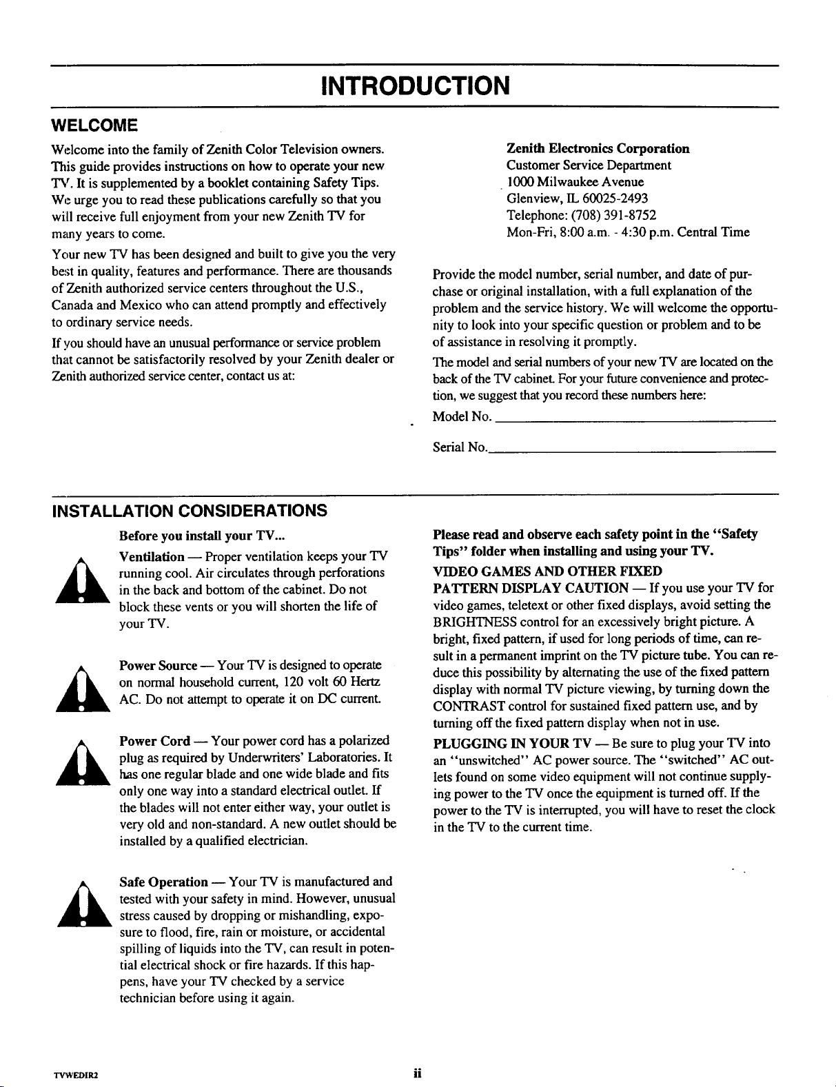
INSTALLATION CONSIDERATIONS
Before you install your TV...
Ventilation -- Proper ventilation keeps your TV
running cool. Air circulates through perforations
in the back and bottom of the cabinet. Do not
block these vents or you will shorten the life of
your TV.
Power Source -- Your TV is designed to operate
on normal household current, 120 volt 60 Hertz
AC. Do not attempt to operate it on DC current.
Power Cord -- Your power cord has a polarized
plug as required by Underwriters' Laboratories. It
has one regular blade and one wide blade and fits
only one way into a standard electrical outlet. If
the blades will not enter either way, your outlet is
very old and non-standard. A new outlet should be
installed by a qualified electrician.
Zenith Electronics Corporation
Customer Service Department
1000 Milwaukee Avenue
Glenview, IL 60025-2493
Telephone: (708) 391-8752
Mon-Fri, 8:00 a.m. - 4:30 p.m. Central Time
Provide the model number, serial number, and date of pur-
chase or original installation, with a full explanation of the
problem and the service history. We will welcome the opportu-
nity to look into your specific question or problem and to be
of assistance in resolving it promptly.
The model and serial numbers of your new TV are located on the
back of the TV cabineL For your future convenience and protec-
tion, we suggest that you record these numbers here:
Model No.
Serial No.
Please read and observe each safety point in the "Safety
Tips" folder when installing and using your TV.
VIDEO GAMES AND OTHER FIXED
PATTERN DISPLAY CAUTION -- If you use your TV for
video games, teletext or other fixed displays, avoid setting the
BRIGHTNESS control for an excessively bright picture. A
bright, fixed pattern, if used for long periods of time, can re-
sult in a permanent imprint on the TV picture tube. You can re-
duce this possibility by alternating the use of the fixed pattern
display with normal TV picture viewing, by turning down the
CONTRAST control for sustained fixed pattern use, and by
turning off the fixed pattern display when not in use.
PLUGGING IN YOUR TV -- Be sure to plug your TV into
an "unswitched" AC power source. The "switched" AC out-
lets found on some video equipment will not continue supply-
ing power to the TV once the equipment is turned off. If the
power to the TV is interrupted, you will have to reset the clock
in the TV to the current time.
Safe Operation -- Your TV is manufactured and
tested with your safety in mind. However, unusual
stress caused by dropping or mishandling, expo-
sure to flood, fire, rain or moisture, or accidental
spilling of liquids into the TV, can result in poten-
tial electrical shock or fire hazards. If this hap-
pens, have your TV checked by a service
technician before using it again.
_WEDIaZ ii
Page 5
CONNECTIONS FOR YOUR TV
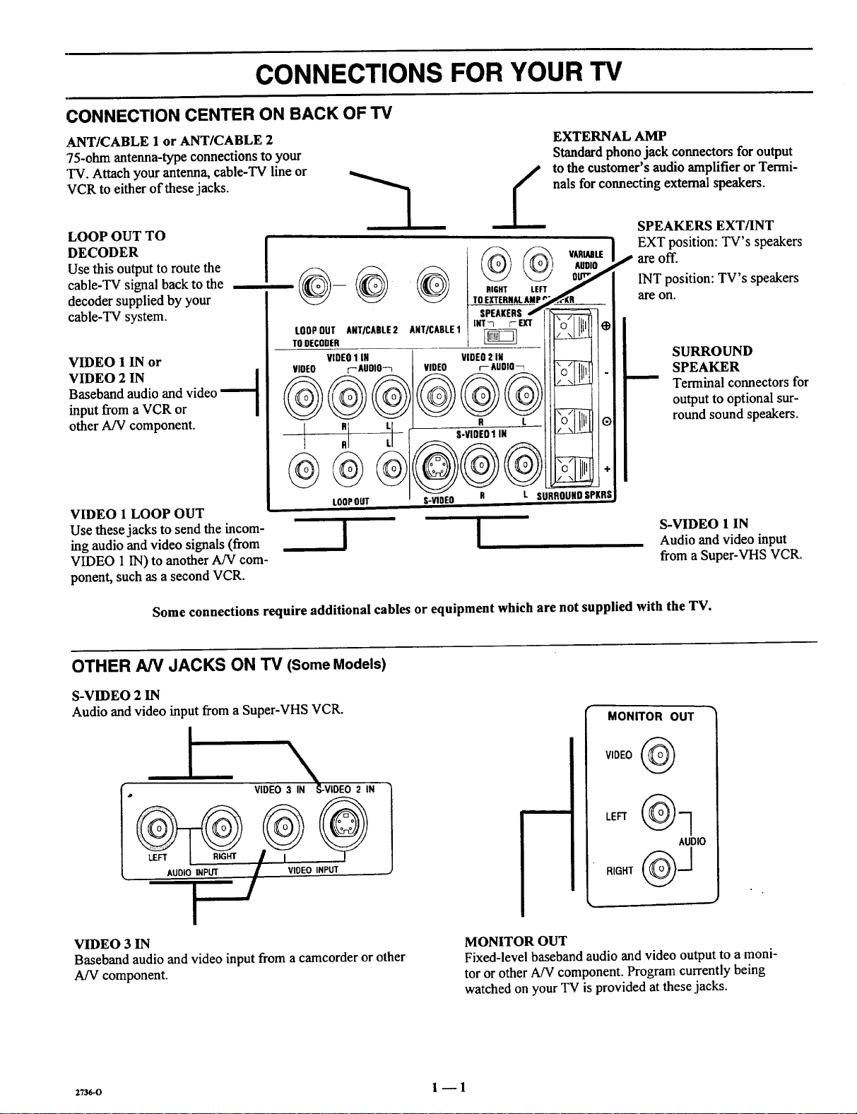
CONNECTION CENTER ON BACK OF TV
ANT/CABLE 1 or ANT/CABLE 2
75-ohm antenna-type connections to your
'IV. Attach your antenna, cable-TV line or
VCR to either of these jacks.
EXTERNAL AMP
Standard phono jack connectors for output
to the customer's audio amplifier or Termi-
nals for connecting external speakers.
LOOP OUT TO
DECODER
Use this outputto route the
cable-TV signal back to the
decoder supplied by your
cable-TV system.
VIDEO 1 IN or
VIDEO 2 IN |
Baseband audio and video
input from a VCR or
other A/V component.
VIDEO 1 LOOP OUT
Use these jacks to send the incom-
ing audio and video signals (from
VIDEO 1 IN) to another A/V com-
ponent, such as a second VCR.
Some connections require additional cables or equipment which are not supplied with the TV.
-1
/_ VARIABLE
!
_ _" TO EXTERNALAMP r_KR _
L00PDU,,,,,C.,E,,,,,.,LE, ilLl
roo_coo=R ----- _ 17--
VIDE01IN VIDEO2 IN , j
VIOEO r--AUDIO-7 VIDEO rAUOIO_ i i]\_'l IIi_1 .
LOOPOUT S-VIOEO R L SURROUNDSPKRS
I
SPEAKERSJ
!
SPEAKERS EXT/INT
EXT position: TV's speakers
I" are off.
INT position: TV's speakers
are on.
SURROUND
SPEAKER
Terminal connectors for
output to optional sur-
round sound speakers.
S-VIDEO 1 IN
Audio and video input
from a Super-VHS VCR.
OTHER AN JACKS ON TV (Some Models)
S-VIDEO 2 IN
Audio and video input from a Super-VHS VCR.
I
AUDIOIINPUT / I VIDEO INPUT
\
VIDEO 3 IN "_o-VIDEO2 IN
I
VIDEO 3 IN
Baseband audio and video input from a camcorder or other
A/V component.
MONITOR OUT
VIDEO (_
AUDIO
MONITOR OUT
Fixed-level baseband audio and video output to a moni-
tor or other A/V component. Program currently being
watched on your TV is provided at these jacks.
27_o 1 -- 1
Page 6
CONNECTIONS FOR YOUR TV
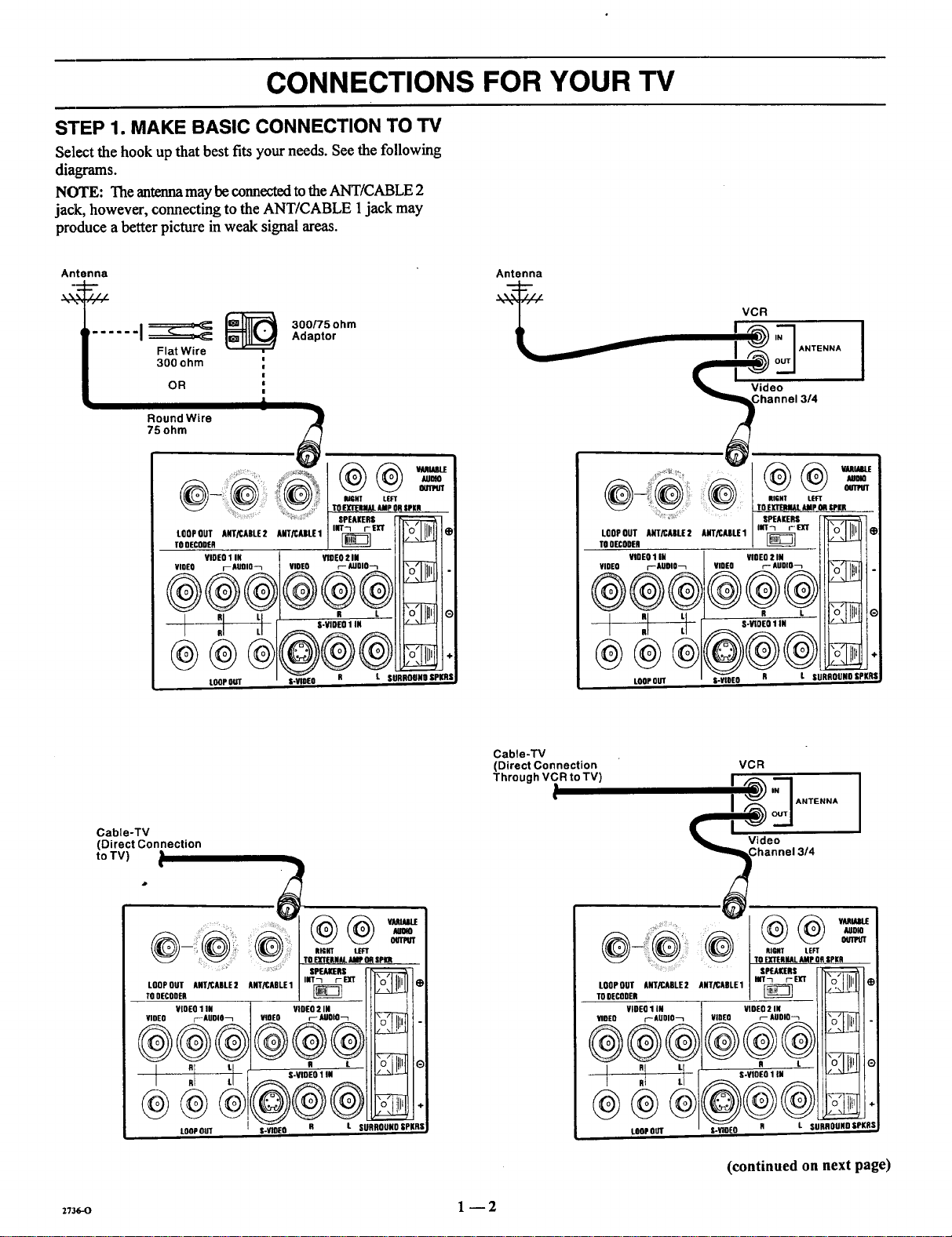
STEP 1. MAKE BASIC CONNECTION TO TV
Select the hook up that best fits your needs. See the following
diagrams.
NOTE: The antenna may be connected to the ANT/CABLE 2
jack, however, connecting to the ANT/CABLE 1jack may
produce a better picture in weak signal areas.
Antenna
...... i_ _ ,,_a_tor_°°'_°hm
Flat Wire
300 ohm
OR '
75ohm
RoundWire i j
LOOP OUT ANT/CABLE 2 ANT/CABLE 1
TO DECODER
VIDEn 1 IN VIDEO 2 IN
VIDEO r AUOIO-_ VIDEO p- AUBIO_
|
!
!
, P,IOHI' LEFT
TO EXTERNALAMp OR SPKR
SPEAKERS _
lilT-1 i-- EXT "n" Jlair
N_
®®®®@®
I RRILLI ,-V,OEO,,"
L_PO_
S-WOEO R L SURROUND SPKRS,
rollllli
Antenna
___i__ VCR
LooPnUT ANT/CABLiE2 ANT/CABLE1
TO OF.CODER
VIDEn 1 IN VInEO 2 IN
VIDEO r'-'-AUOIO_ VIOEO r-- AUDIO_
® @
i :i :1 s.mEn,iR
LOOPOUT
SPEAKERS
IIIT_ tEXT
R L
Cable-TV
(Direct Connection
to TV)
TO EXTERNALAMP OA SpI(R
LOOPOUT ANT/CABLE2 ANT/CABLE1
TOOECODER
VlOEn I Ifl VIDEO 2 IN
VIDEO t-_ AUDIO_ VIDEO F AOOlO
n tl i s VIOEnllN
I Rl L_ "
LOOPOUT
! R t SURRODNO 8PKRS
INT_ r_CT I_
SPEAKERS
_,-o 1 --2
Cable-'lV
(Direct Connection
Through VCR to TV)
___ Chlnnel 3/4
• AUDIO
_/ TO EXTERNALAMP OR SPKR
LOOP OUT ANT/CABLE 2 ANT/CABLE 1
TODECODER
VIDEn 1 IN
VIOEO r-AUOIO_
®®@
.... SPF.AKtRS
VIDEO r- AUDIO_
®®®
LOOPOUT S-YIOEO
VCR
,_,_
I _ / ANTENNA
RIGIT LEFT
HIT-I rEfiT
VIDEO 2 IN
R L
S-VIDEO 1IN
R L SURROUNn SPI(RS
(continued on next page)
G
Page 7

CONNECTIONS FOR YOUR TV
STEP 1. MAKE BASIC CONNECTION TO TV
DECODER/
CONVERTER
LOOPOUT ANTiCADLE2 ANTRAALE1 lilT--t rEX?
TODECOOER
VIDEO1IN VIOEO! III
VIDEO I--AUDIO"7 VIOEO r'-AUDIO7
! :1
@@
LOOPOUT
L SURROUND SPKR$
DECODER/
CONVERTER
IN
Cable-TV
Direct
I
LOOP oo]r ANT/CABLE 2 ANTICABLE 1
TO 9ECOOER
VIDEO 1 IN VIDEO 2 IN
VlOEO f--AUDIO"7 VIDEO r-- AUDIO"7
Video
I Channel 314
OUT
.... ..... ..... ," J-'_\ //_\ VARIABLE
I ':,1'-i, .-,,OE0',,,,
LOOPOUT UR PKR|
VCR
ANTENNA
I
INT-I_ r'- I_[T _
STEP 2. MAKE VCR CONNECTIONS TO TV
If you have a stereo VCR, you must make the A/V connec-
tions shown in order to hear stereo sound while playing a tape.
STEREO VCR
OUTPUTS
I VIDEO R AUDIO L
I
STEREOVCR
OUTPUTS
I VIDEO R AUDIO L
@@
Connections for second ster-
eo VCR oralternate connec-
tions for first VCR.
S-VIOEO 1 IN
LOOPOUT S-VIDEO R
:,73_,-o 1 -- 3
t SURROUND SPKRS
Page 8

CONNECTIONS FOR YOUR TV
STEP 3. MAKE SUPER-VHS VCR CONNECTIONS TO TV
:.......... TOEXTERNALAMp OR |PKR
LOOPOUT ANT/CABLE2 ANT/CABLE1 INT7 tEXT
TODECODER
YlOfO rAUDIO_ VIDEO r-- AUDID_
.... _ ::: SPEAKERS
SUPER-VHSVCR
VIDEO 1 IN VIDEO 2 IN
0
LOOPOUT S-VIDEb_-. R _//\
STEP 4 MAKE A/V CONNECTIONS TO AUXILIARY AN JACKS (VIDEO 3 IN OR S-VIDEO 2 IN)
VIDEO 3 IN S-VIDEO 2 IN
VIDEO INPUT
Stereo Camcorder
STEP 5 MAKE CONNECTIONS TO MONITOR OUT JACKS
Stereo VCR
or Camcorder
IVIDEO R AUDIO L I
°o- l
J INPUTS i
VIDEO 3 IN S-VIDEO 2 IN
@
Monitor
! ]
RIGHT . o "
%
"- Component ..""
2_-(, l -- 4
• o i
__°oo°
Other A/V °"
o
o_
Page 9

CONNECTIONS FOR YOUR TV
STEP 6. MAKE SURROUND SOUND CONNECTIONS TO TV
1. Mount and connect the optional surround sound
speakers by following the instructions provided with
the speakers.
2. Use the SURROUND option in the AUDIO Menu to
adjust the volume of the surround speakers.
. The level of the surround sound varies relative to the
difference between the left- and right-channel stereo
signals.
NOTE: MAKE SURE TV IS OFF
WHILE CONNECTING SPEAKERS.
-- RIGHT LEFT
@@--=,
.... TO EXTERNAL AMP OR SPKR
SPEAKERS _1_1_::::_-i
Surround
Speaker
(8 ohm)
,ooPou,,RT_ARU2,=/CARLE,,,r_ IIXI,', :.,
,ODEOOO'R _ _1'1
VIDEO rAUOlO_ VIDEO r AUDIO_ I_l r,.'l I - I
R L R L /\l' O
I RJ L [ S-VIDEO1 IN I_ _
LOOP OUT S-VIDEO R L SURROUN9 SPKRS I
STEP 7. MAKE EXTERNAL SPEAKER CONNECTIONS TO TV
1. Place the SPEAKERS EXT/INT switch on the TV in 3. Place the SPEAKERS EXT/INT switch on the TV in
the INT position, the EXT position.
2. Connect the two external speaker terminals.
Surround
Speaker
(8 ohm)
NOTE: MAKE SURE TV IS OFF
WHILE CONNECTING SPEAKERS.
Right
Speaker
(8 ohm)
RIGHT LEFT
....... I SPEAKERS _-
LOOPOUT ANT/CABLE2 ADTRABLE1 I INT_ ExT _ *
TO DECODER
VIDEO1 IN VIDEO2IH
-- _ S-VIDEO 1 IN
D _ D , i io:llL!
I RI LL _ i
LOOPOUT S-V DEO R L SURROUND OPKRS
2736-o 1 --5
Left
Speaker
(8 ohm)
Page 10
CONNECTIONS FOR YOUR TV
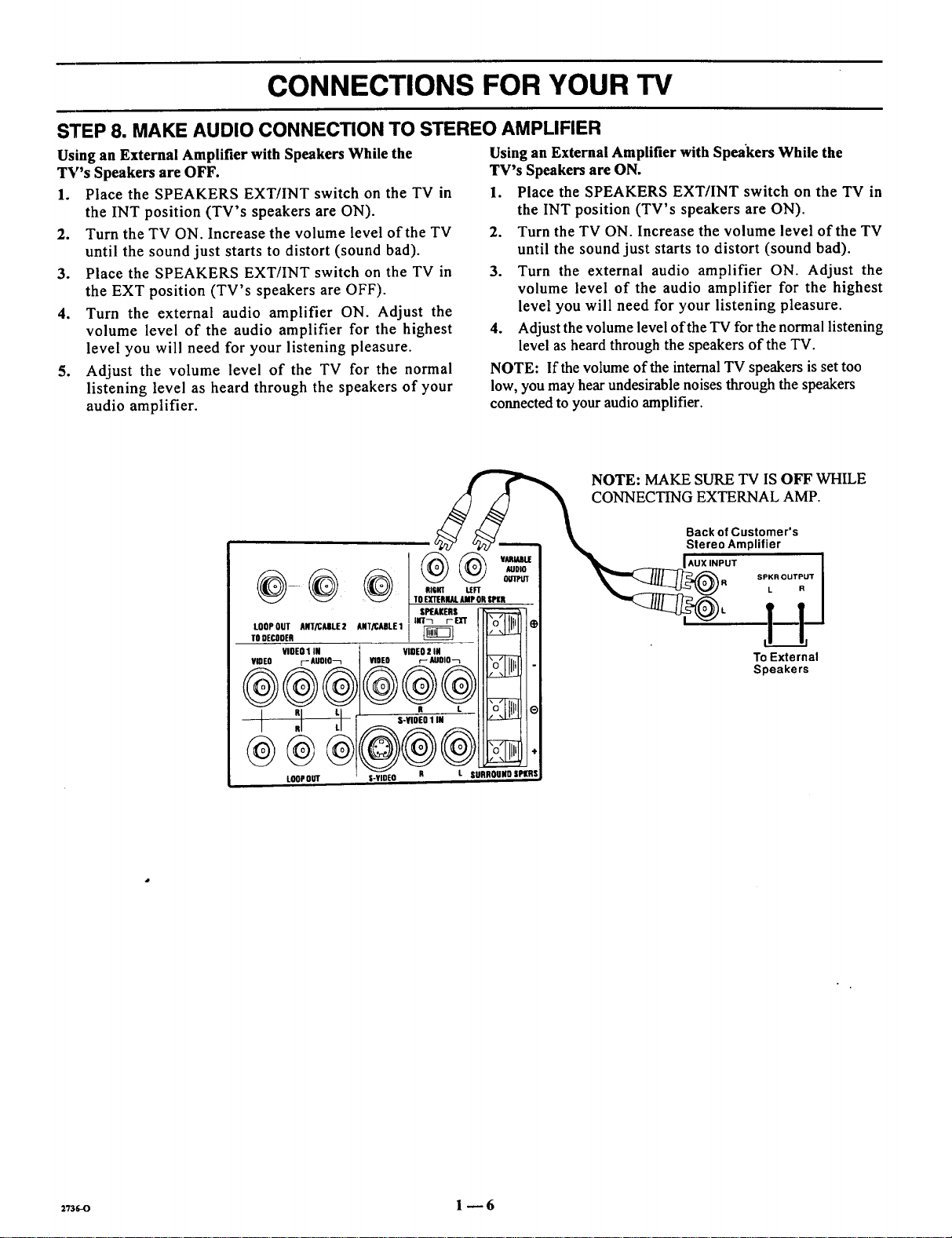
STEP 8. MAKE AUDIO CONNECTION TO STEREO AMPLIFIER
Using an External Amplifier with Speakers While the
TV's Speakers are OFF.
1. Place the SPEAKERS EXT/INT switch on the TV in
the INT position (TV's speakers are ON).
2. Turn the TV ON. Increase the volume level of the TV
until the sound just starts to distort (sound bad).
3. Place the SPEAKERS EXT/INT switch on the TV in
the EXT position (TV's speakers are OFF).
4. Turn the external audio amplifier ON. Adjust the
volume level of the audio amplifier for the highest
level you will need for your listening pleasure.
5. Adjust the volume level of the TV for the normal
listening level as heard through the speakers of your
audio amplifier.
(__NOTE: MAKE SURE TV IS OFF WHILE
Using an External Amplifier with Speakers While the
TV's Speakers are ON.
1. Place the SPEAKERS EXT/INT switch on the TV in
the INT position (TV's speakers are ON).
2. Turn the TV ON. Increase the volume level of the TV
until the sound just starts to distort (sound had).
3. Turn the external audio amplifier ON. Adjust the
volume level of the audio amplifier for the highest
level you will need for your listening pleasure.
4. Adjust the volume level of the TV for the normal listening
level as heard through the speakers of the TV.
NOTE: If the volume of the internal TV speakers is set too
low, you may hear undesirable noises through the speakers
connected to your audio amplifier.
@@
LOOPOUT ANT/CAIILE2 ANT/CABLE1
TODECODER
VIOEO1 IN
VWEO F-AUOIO_ VIDEO
,UT__<_m "o'1111_$ I _ l--ld
VIDEO2 IN
r-_Jolo-_ _ . To External
_- "---_4_. o_)L f f I
@@
CONNECTING EXTERNAL AMP.
Back of Customer's
Stereo Amplifier
UX INPUT l
sPK.ou, u+i
Speakers
LOOP OUT
2736.-o 1 --6
R L SURROUNDIPKRS
Page 11
THE FIRST TIME YOU OPERATE YOUR TV
STEP 1. CONNECT THE POWER
A. Plug your TV into an unswitched AC power source.
B. Turn the TV ON by pressing OFF-ON.
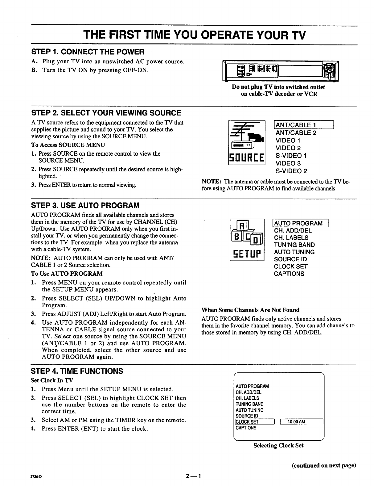
STEP 2. SELECT YOUR VIEWING SOURCE
A TV source refers to the equipment connected to the TV that
supplies the picture and sound to your TV. You select the
viewing source by using the SOURCE MENU.
To Access SOURCE MENU
1. Press SOURCE on the remote control to view the
SOURCE MENU.
2. Press SOURCE repeatedly until the desired source is high-
lighted.
3. Press ENTER to return to normal viewing.
STEP 3. USE AUTO PROGRAM
AUTO PROGRAM finds all available channels and stores
them in the memory of the TV for use by CHANNEL (CH)
Up/Down. Use AUTO PROGRAM only when you first in-
stall your TV, or when you permanently change the connec-
tions to the TV. For example, when you replace the antenna
with a cable-TV system.
NOTE: AUTO PROGRAM can only be used with ANT/
CABLE 1 or 2 Source selection.
To Use AUTO PROGRAM
1. Press MENU on your remote control repeatedly until
the SETUP MENU appears.
2. Press SELECT (SEL) UP/DOWN to highlight Auto
Program.
3. Press ADJUST (ADJ) Left/Right to start Auto Program.
4. Use AUTO PROGRAM independently for each AN-
TENNA or CABLE signal source connected to your
TV. Select one source by using the SOURCE MENU
(AN'I_/CABLE 1 or 2) and use AUTO PROGRAM.
When completed, select the other source and use
AUTO PROGRAM again.
NI
Do not plug TV into switched outlet
on cable-TV decoder or VCR
IANT/CABLE 1
ANT/CABLE 2
VIDEO 1
VIDEO 2
5DUFIEE
NOTE: The antenna or cable must be connected to the TV be-
fore using AUTO PROGRAM to find available channels
_I [AUTO PROGRAM ]
When Some Channels Are Not Found
AUTO PROGRAM finds only active channels and stores
them in the favorite channel memory. You can add channels to
those stored in memory by using CH. ADD/DEL.
S-VIDEO 1
VIDEO 3
S-VIDEO 2
CH. ADD/DEL
CH. LABELS
TUNING BAND
AUTO TUNING
SOURCE ID
CLOCK SET
CAPTIONS
STEP 4. TIME FUNCTIONS
Set Clock In TV
1. Press Menu until the SETUP MENU is selected.
2. Press SELECT (SEL) to highlight CLOCK SET then
use the number buttons on the remote to enter the
correct time.
3. Select AM or PM using the TIMER key on the remote.
4. Press ENTER (ENT) to start the clock.
Z_D 2- 1
AUTOPROGRAM
CH.ADD/DEL
CH.LABELS
TUNINGBAND
AUTOTUNING
SOURCEID
ICLOCKSET
CAPTIONS
Selecting Clock Set
[ I 10:00AM
(continued on next page)
Page 12
THE FIRST TIME YOU OPERATE YOUR TV
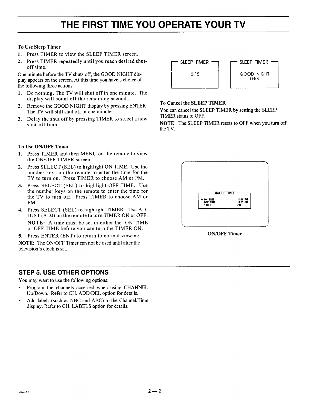
To Use Sleep Timer
1. Press TIMER to view the SLEEP TIMER screen.
2. Press TIMER repeatedly until you reach desired shut-
off time.
One minute before the TV shuts off, the GOOD NIGHT dis-
play appears on the screen. At this time you have a choice of
the following three actions.
1. Do nothing. The TV will shut off in one minute. The
display will count off the remaining seconds.
2. Remove the GOOD NIGHT display by pressing ENTER.
The TV will still shut off in one minute.
3. Delay the shut off by pressing TIMER to select a new
shut-off time.
To Use ON/OFF Timer
1. Press TIMER and then MENU on the remote to view
the ON/OFF TIMER screen.
2. Press SELECT (SEL) to highlight ON TIME. Use the
number keys on the remote to enter the time for the
TV to turn on. Press TIMER to choose AM or PM.
3. Press SELECT (SEL) to highlight OFF TIME. Use
the number keys on the remote to enter the time for
the TV to turn off. Press TIMER to choose AM or
PM.
4. Press SELECT (SEL) to highlight TIMER. Use AD-
JUST (ADJ) on the remote to turn TIMER ON or OFF.
NOTE: A time must be set in either the ON TIME
or OFF TIME before you can turn the TIMER ON.
5. Press ENTER (ENT) to return to normal viewing.
NOTE: The ON/OFF Timer can not be used until after the
television's clock is set.
GOOD NIGHT
r SLEEP TIMER "-_
0:15
_ SLEEP TIMER "-_
0:58
To Cancel the SLEEP TIMER
You can cancel the SLEEP TIMER by setting the SLEEP
TIMER status to OFF.
NOTE: The SLEEP TIMER resets to OFF when you turn off
the TV.
-- ON/OFFTIMER
"> ON TIME 11:51 PM
OFF TIME 12:00 PM
TIMER ON
ON/OFF Timer
STEP 5. USE OTHER OPTIONS
You may want to use the following options:
• Program the channels accessed when using CHANNEL
Up/Down. Refer to CH. ADD!DEL option for details.
• Add labels (such as NBC and ABC) to the Channel/Time
display. Refer to CH. LABELS option for details.
273_,-o 2--2
Page 13
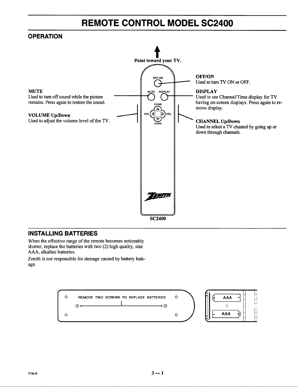
OPERATION
REMOTE CONTROL MODEL SC2400
t
Point toward your TV.
MUTE
Used to turn off sound while the picture
remains. Press again to restore the sound.
VOLUME Up/Down
Used to adjust the volume level of the TV.
OFF-ON
©
MUTE DISPLAY
©©
CHAN
SC2400
OFF/ON
Used to turn TV ON or OFF.
DISPLAY
Used to see Channel/Time display for TV
having on-screen displays. Press again to re-
move display.
CHANNEL Up/Down
Used to select a TV channel by going up or
down through channels.
INSTALLING BATTERIES
When the effective range of the remote becomes noticeably
shorter, replace the batteries with two (2) high quality, size
AAA, alkaline batteries.
Zenith is not responsible for damage caused by battery leak-
age.
REMOVE TWO SCREWS TO REPLACE BATTERIES
®, [ (3
[
2736-0 3 -- 1
O
Page 14
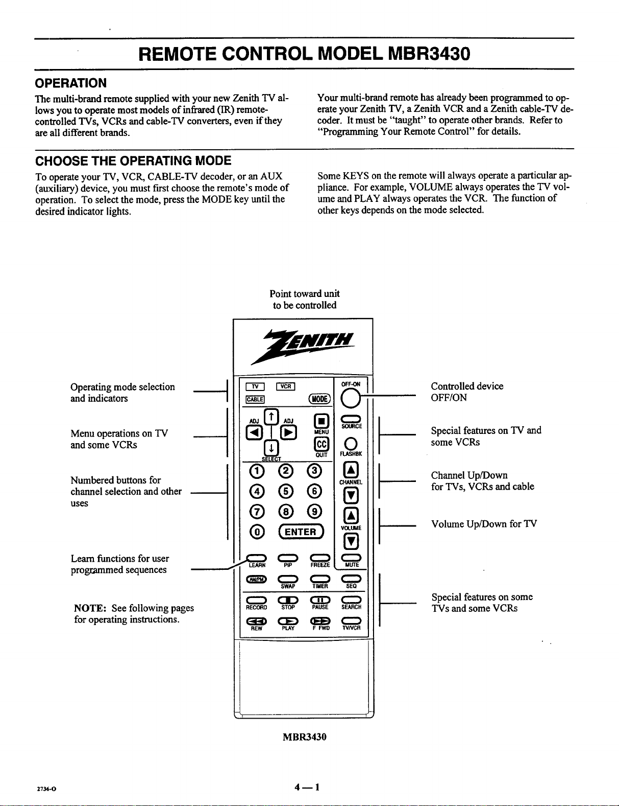
REMOTE CONTROL MODEL MBR3430
OPERATION
The multi-brand remote supplied with your new Zenith "IV al-
lows you to operate most models of infrared (IR) remote-
controlled TVs, VCRs and cable-TV converters, even if they
areall different brands.
CHOOSE THE OPERATING MODE
To operate your TV, VCR, CABLE-TV decoder, or an AUX
(auxiliary) device, you must first choose the remote's mode of
operation. To select the mode, press the MODE key until the
desired indicator lights.
Point toward unit
to be controlled
Your multi-brand remote has already been programmed to op-
erate your Zenith TV, a Zenith VCR and a Zenith cable-TV de-
coder. It must be "taught" to operate other brands. Refer to
"Programming Your Remote Control" fordetails.
Some KEYS on the remote will always operate a particular ap-
pliance. For example, VOLUME always operates the TV vol-
ume and PLAY always operates the VCR. The function of
other keys depends on the mode selected.
Operating mode selection
and indicators
Menu operations on TV
and some VCRs
Numbered buttons for
channel selection and other
uses
Learn functions for user
programmed sequences
NOTE: See following pages
for operating instructions.
® ® ®
® ®®
@ (ENTE.)
(H_) (:_ (:Z)
C:_ CID CZD C_
RECORD STOP PAUSE SEARCH
SWAP TIMER SEQ
REW PLAY F FWO TVNCR
Controlled device
OFF/ON
Special features on "IV and
some VCRs
Channel Up/Down
for TVs, VCRs and cable
Volume Up/Down for TV
Special features on some
TVs and some VCRs
_1 1_
MBR3430
z'l_-o 4 -- 1
Page 15

REMOTE CONTROL MODEL MBR3430
13/OPERATIONS
The following functions and operations apply to your Zenith
TV. The remote control must be in the TV mode to operate
your TV.
MODE
Used to select the TV mode of
operation.
TV
Lights when TV mode of
operation is selected.
CC (Closed Captions)
Used to view closed captions
broadcast with some television
programs.
MENU, SELECT and ADJUST
Used with on-screen menus to
see menu, select an option, and
adjust that option.
Numbered Buttons
Used to select a TV channel.
ENTER
Used to view the Channel/Time
Display orto remove any on-
screen menu or display.
LEARN
Used to program remote.
PIP
Used to _tctivatePicture-In-Pic-
ture inset.
SWAP
Used to swap picture in PIP inset
with the main television picture.
t
Point toward your TV.
QUIT
®®Q
®®®
®®@
PIP
STOP PAUSE
C]D
REW PLAY F FWD
OFF/ON
Used to turn TV ON or OFF.
SOURCE
Used to display the menu of TV
sources for some TVs. Press again
step through the source selec-
tions. On some TVs, press to select
AUX (Auxiliary) channel.
FLASHBK (Flashback)
Used to return to the last TV
channel you were watching.
CHANNEL Up/Down
channels.
Used tosequence through the TV
VOLUME Up/Down
Used to adjust the TV's volume.
MUTE
Used to turn off sound while the
picture remains. Press again to re-
store the sound.
SPATIAL EQUALIZATION
(SEq)
Used to select SEQ audio mode on
TVs equipped with SEQ feature.
FREEZE
Used to freeze the motion of the pic-
ture on the PIP inset.
TIMER
Used to activate the SLEEP
TIMER. Press repeatedly to select
desired turn-off time.
273_-o 4--2
Page 16

REMOTE CONTROL MODEL MBR3430
VCR OPERATIONS
The following functions and operations apply to Zenith VCR
models built after 1988. The remote control must be in the
VCR mode to operate your VCR.
The remote control supplied with your VCR may have keys
not duplicated on the new remote. If these functions are de-
sired, the original remote control will have to be used.
t
MODE
Used to select the VCR mode of
operation.
VCR
Lights when VCR mode of
operation is selected.
MENU, SELECT, ADJUST
and QUIT
Used with on-screen menus and pro-
gramming options of the VCR. See
VCR operating guide for details.
Nu mbered Buttons
Used to select a TV channel through
the VCR. Also, used to set the
t_ter in the VCR, and to enter pro-
gramming information.
ENTER
Used with the numbered buttons to se- /
lect a TV channel through the VCR.
AM/PM
Used to set timer during program-
ming.
Point toward your VCR.
ADJ _ ADJ
CHANNEL
®®®
0@@
VOLUME
LEARN PIP
SWAP TIMER SEO
RECORD STOP PAUSE SEARCH
I 3> CED r,.--,,
REW PLAY F FWD TVNCR
OFF/ON
Used to turnVCR ON or OFF.
FLASHBK (Flashback)
Used during VCR playback to
view the channel tuned by the
VCR.
Used to sequence through channels
h CHANNEL Up/Down
on the VCIL
TIMER
Activates TIME RECORD on
some VCRs. See the VCR operat-
ing guide for details.
TV/VCR
Used to select the source of the pro-
grams seen on the TV. Switches
the VCR between TV mode and
VCR mode.
TV Mode: Channels are selected
through the TV.
VCR Mode: Channels or tape op-
eration are selected through the
VCR.
27_-o 4 _ 3
RECORD, STOP, PAUSE,
SEARCH, REW, PLAY and
F FWD
Used for tape recording and play-
back functions. See the VCR operat-
ing guide for details.
Page 17

REMOTE CONTROL MODEL MBR3430
CABLE-TV OPERATIONS
The following functions andoperationsapply to a Zenith cable-
TV decoder. The remote control must be in the CABLE mode to
operateyour cable-TV decoder.
The remote control supplied with your cable-TV decoder may
have keys not duplicated on the new remote. If these functions
are desired, the original remote control will have to be used.
t
MODE
Used to select the Cable mode of
operation.
CABLE
Lights when CABLE mode of
operation is selected.
MENU, SELECT, ADJUST
and QUIT
Functions depend on Cable-TV sys-
tem. See Cable-TV decoder operat-
ing guide for details.
Numbered Buttons
Used to select channels through
Cable-TV decoder.
ENTER
Used with the numbered buttons to se- /
lect a TV channel through the
Cable-TV decoder.
Point toward your Cable-TV decoder.
OFF-ON
SOURCE
0
FLASHBK
®®®
®®®
®®@
_.._,_ ENTER )
LEARN PIP FREEZE
SWAP TIMER SEO
RECORD STOP PAUSE SEARCH
(3D
IAI
MUTE
OFF/ON
Used to turn VCR ON or OFF.
SOURCE
Selects "A" or "B" cable channels.
Used to sequence through channels
b CHANNEL Up/Down
on the Cable-TV decoder.
REW PLAY F FWD TVNCR
2736-0 4 -- 4
(
Page 18

REMOTE CONTROL MODEL MBR3430
PREPARATION FOR USE
Batteries are provided with this remote, but you must install
them before using the remote.
INSTALLING BATTERIES
When the effective operating range of your remote becomes
noticeably shorter, replace the batteries with two high-quality,
alkaline, size AAA batteries.
Zenith is not responsible for damage caused by battery leak-
age.
Atter installing new batteries, the remote control will set itself
to Zenith brand codes, as follows: TV=I01, VCR=201 and
CABLE=301.
If you are going to operate equipment that uses different
codes, the remote must be reprogrammed for those codes.
Step 1. Step 2. Step 3.
2_-o 4 -- 5
Page 19

REMOTE CONTROL MODEL MBR3430
PROGRAMMING BRAND CODES
Introduction
Before using your new remote control, it must be programmed
to recognize the brands of equipment it will be used to oper-
ate. If you arc using a Zenith VHS VCR or a Zenith cable-TV
decoder, the remote has already been programmed for you.
Find the code that corresponds to each brand and type of
equipment you are going to operate. Refer to Tables 1, 2 and 3.
For example, if you were programming the remote for use
with a Zenith "IV, you would look for "Zenith" in "Table 1",
and f'md code" 101."
Write the brand codes for your equipment on the following
lines.
TV CODE:
CABLE CODE:
VCRCODE:
1. Press MODE repeatedly to select the desired TV,
VCR or CABLE operating mode for the remote.
2. Press LEARN for about 5 seconds until the MODE
indicator lights for the selected TV, VCR or CABLE
mode of operation.
3. Enter the proper brand code number for the equipment
to be controlled.
4. Press LEARN. All three mode indicators should light
briefly, then turn off to indicate the brand code has
been programmed.
5. If all three mode indicators fail to light briefly, an
error has occurred. Repeat Steps 1-4 to try again.
6. Repeat steps 1-4 to program the remote for the other
equipment you are using.
NOTE: CABLE mode can be programmed to operate a sec-
ond TV or second VCR, if desired.
When batteries are removed: It will be necessary to reprogram
the proper VCR and cable-TV decoder codes.
Operating Mode
Indicators
Numbered Buttons
Use to enter code number
for desired brand.
LEARN Button
I
®®®
®®®
@ (E.TE.)
LEARN PiP FREEZE
C_ C_ C_
SWAP TIMER SEQ
(_D OD OD O
RECORD STOP PAUSE SEARCH
REW PLAY F _,lO I_NCR
Operating MODE Selector
CHANNEL :
I!)
VOLUME
UUTE
I ]'
27u_o 4 m 6
Page 20

REMOTE CONTROL MODEL MBR3430
TV, VCR AND CABLE-TV OPERATING CODES
Table 1. TV Codes by Brand
TV Brand TV Brand
Name Code Name Code
Admiral 116 Montgomery Ward 119
Admiral 121 Montgomery Ward 121
Akai 104 Montgomery Ward 130
Amark 103 NEC 104
AOC 104 NEC 119
Bell & Howell 121 Panasonic 106
Centurion 119 Panasonic 107
Coronado 103 Philco -103
Curtis Mathes 116 Philco 104
Curtis Mathes 119 Philco 112
Curtis Mathes 121 Philco 113
Daytron 119 Philips 112
Emerson 103 Philips 113
Emerson 104 Pioneer 135
Emerson 123 Portland 103
Emerson 124 Quasar 106
Emerson 131 Quasar 107
Emerson 136 Realistic 105
Fisher 109 Realistic 123
Fisher 118 Realistic 124
G¢neral Electric 106 RCA 104
General Electric 107 RCA 116
General Electric 114 RCA 126
General Electric 116 Sampo 119
Goldstar 103 Samsung 103
Goldstar 104 Samsung 119
Goldstar 119 Samsung 134
Hitachi 102 Sanyo 108
Hitachi 103 Sanyo 109
Hitachi 129 Sanyo 118
JVC 125 Scott i 19
JVC 132 Sears 103
J.C. Penney 104 Sears 108
J.C. Penney 110 Sears 109
J.C. Penney 114 Sears ! 10
J.C. Penney 117 Sears 111
J.C. Penney 119 Sears 118
KMC 103 Sears 134
KTV 103 Sharp 103
KTV 104 Sharp 105
Lodgenet 121 Sharp 122
Logik 121 Sharp 133
LXI 133 Sharp 137
LXI 137 Sony 115
lVlagnavox ,, 103 Sylvania 112
IVlagnavox 112 Sylvania 113
IVlagnavox 113 Sylvania 117
Ivlagnavox 119 Sylvania 119
/vlagnavox 127 Sylvania 127
Magnavox 128 Sylvania 128
Majestic 121 Tatang 106
Marantz 104 Teknika 103
Marantz 120 Teknika 112
Memorex 121 Teknika 121
MGA/Mitsubishi 104 Teknika 124
MGA/Mitsubishi 119 Telerent 103
MGA/Mitsubishi 120 Telerent 121
MGA/Mitsubishi 130 Toshiba 110
Montgomery Ward 103 Toshiba III
Montgomery Ward 104 Toshiba 134
Montgomery Ward 105 Yorx 119
Montgomery Ward 113 Zenith 101
Montgomery Ward 114
Table 2. VCR Codes by Brand
VCR Brand VCR Brand
Name Code Name Code
Akai 223 Pentax 215
Audio Dynamics 202 Philco 214
Audio Dynamics 218 Philips 214
Broksonic 221 Philips 227
Canon 214 Pioneer 210
Citizen 209 Pioneer 215
Craig
Curtis Mathes 214
Curtis Mathes 215
DBX 216
DBX 220
Emerson 227
Emerson 206
Emerson 208
Emerson 212
Emerson 214
Emerson 231
Fisher 220
Fisher 230
Fisher 206
Funai 212
General Electric 204
General Electric 205
General Electric 233
Goldstar 206
Hitachi 209
Instant Replay 21I
Instant Replay 212
JVC 215
JVC 208
J.C. Penney 232
J.C. Penney 217
J.C. Penney 207
'Kenwood 214
Magnavox 227
Magnavox 23I
Marantz 209
Marantz 202
Marta 202
Memorex 231
Memorex 234
Memorex 205
MGA/Mitsubishi 215
MGA/Mitsubishi 204
Montgomery Ward 208 Vector Research 218
Montgomery Ward 214 Yamaha 202
Montgomery Ward 219 Yamaha 218
NEC 202 Zenith VHS 201
NEC 218 Zenith VHS 225
Panasonic 214 Zenith VHS 229
212 Pioneer Laser Disk 228
214 Quasar
216 RCA
202 RCA
218 RCA
203 RCA
221 Realistic
223 Realistic
226 Realistic
233 Realistic
235 Realistic
211 Samsung
212 Samsung
213 Sanyo
231 Sanyo
214 Scott
216 Scott
220 Scott
209 Sears
215 Sears
214 Sears
227 Sears
202 Sears
225 Sharp
214 Sony VHS
218 Sony Video 8
227 Sylvania
202 Sylvania
207 Sylvania
214 Symphonic
207 Tashiko
218 Tatung
209 Teac
212 Teac
214 Teknika
231 Toshiba
204 Toshiba
222 Vector Research
Table 3. Cable Decoder Codes by
Brand
Cable Decoder Cable Decoder
Brand Name Code Brand Name Code
Drake Satellite 312 Pioneer 315
Drake Satellite 330 Regency 329
Gemini 305 Samsung 335
Gemini 331 Scientific Atlanta 316
General Instrument 305 Scientific Atlanta 323
General Instrument 306 Scientific Atlanta 336
Hamlin 302 Sprucer
Hamiin 303 (Panasonic) 313
Jerrold 304 Standard
Jerrold 307 Components 335
Jerrold 308 STS Satellite 324
Jerrold 309 Telecaption 4000 325
Jerrold 310 Tocom 317
Kale Vision 335 Tocom VIP 318
Macom 314 Toshiba 322
Macom 321 Toshiba Satellite 319
Macom Satellite 322 Zenith 301
Magnavox 334 Zenith 322
NSC 335 Zenith AV3000 327
Oak 311 Zenith SateUite 312
Oak 332 Zenith Satellite 330
Panasonic 313 Zenith Satellite 328
Panasonic 320 Zenith Laser Disk 326
Paragon (Zenith) 333
_:736-o 4 m 7
Page 21

QUICK REFERENCE TO ON-SCREEN MENUS
AVAILABLE MENUS
Your TV is icon and menu operated. That is, an icon is se-
lected at the top of the TV screen and a menu of adjustment
options appears.
DURI'E
[AUTO PROGRAM
CH. ADD/DEL
CH. LABELS
TUNING BAND
AUTO TUNING
SOURCE ID
CLOCK SET
CAPTIONS
SUMMARY OF MENU ITEMS
JANT/CABLE 1
ANT/CABLE 2
VIDEO 1
VIDEO 2
DURI'E
* Some models only.
S-VIDEO 1
VIDEO 3 _-
S-VIDEO 2
t;ETUP
FIUDID [/IDED,
\
Unhighlighted
Highlighted
Menu for highlighted icon appears
at left of TV screen.
ANT/CABLE 1 or 2 : Either of these sources may be used
for input from anantenna or a cable-TV line.
VIDEO 1 or 2 : Eitherof these sources may be used for input
from a VCR.
S-VIDEO 1 : Use this source ifa Super-VHS VCR is con-
nected to your TV.
VIDEO 3 : Use this source ira camcorder is connected to
your TV.
S-VIDEO 2 : Use this source if a second Super-VHS VCR is
connected to your TV.
PIP
[AUTO PROGRAM
CH. ADD/DEL
CH. LABELS
TUNING BAND
AUTO TUNING
SOURCE ID
CLOCK SET
CAPTIONS
AUTO PROGRAM: Finds all available channels and stores
them in the memory of the TV for use with CHANNEL
Up/Down.
_3_o 5 -- 1
CH. ADD/DEL: Changes the list of active channels stored in
memory so that only your favorite channels areselected when
using CHANNEL Up/Down.
CH. LABELS: Adds a channel label or name to the
channel/time display. For example, ABC may appearwhen
this network channel is tuned.
TUNING BAND: Determines the operation of the channel se-
lector inside the TV.
AUTO TUNING: Lets your TV compensate fo_ variations in
broadcast and cable-TV frequencies.
SOURCE ID: Lets you assign a relevant name to each input
source.
CLOCK SET: Sets the TV's internal clock.
CAPTIONS: Displays closed captions (CC) or informational
text when available.
Page 22

QUICK REFERENCE TO ON-SCREEN MENUS
SUMMARY OF MENU ITEMS
IBASS
TREBLE
BALANCE
AUDIO
Ru01n
SEQ
SURROUND
BRIGHTNESS
COLOR
TINT
SHARPNESS
glOE0 COLORTEMP
VIDEO FILTER
AUTO FLESH
PICTURE PREF
BASS: Adjusts the BASS (low-frequency) level.
TREBLE: Adjusts the TREBLE (high-frequency) level.
BALANCE: Adjusts the BALANCE of sound between the
lett and right speakers for stereophonic programs.
AUDIO MODE: Allows for receiving a Second Audio Pro-
gram (SAP), such as a program broadcast with two audio por-
tions (typically two languages), or lets you select stereophonic
(STEREO) or monaural (MONO) speaker operation.
SEQ: Turns on an enhanced stereo mode.
SURROUND: Adjusts Surround Sound volume when used
with separately supplied Surround Sound speakers.
CONTRAST: Adjusts the overall contrast and color level of
the picture.
BRIGHTNESS: Adjusts the brightness level of black areas in
the picture.
COLOR: Adjusts the intensity of the colors in the picture.
TINT: Adjusts the color of the flesh tones.
SHARPNESS: Adjusts the clarity of the edges of objects for the
clearest possible picture.
COLOR TEMP: Changes the "color temperature" or picture
white balance between cooler natural whites and warmer (red)
colors.
VIDEO FILTER: Reduces video "noise" or interference in
dark picture areas resulting in clearer overall pictures.
AUTO FLESH: Automatically maintains natural skin tones
under changing scene and video source conditions.
PICTURE PREF: Lets you decide if you want to use your
own CUSTOM video settings, the factory PRESET video set-
tings, or the THEATER video settings for optimum viewing in
low-light conditions.
ICH. GUIDE
CH. REVIEW
PIP SOURCE
PIP COLOR
PIP
* Some models only.
2_-o 5 -- 2
PIP TINT
PIP SIZE
CH. GUIDE: Provides a visual review of all channels in the
channel scan memory for the currently selected ANT/
CABLE source.
CH. REVIEW: Provides a visual review of the last three (3)
channels tuned on the TV.
PIP SOURCE: Lets you select the equipment that supplies
the picture to the PIP inset.
PIP COLOR: Adjusts the intensity of the colors in the PIP in-
set.
PIP TINT: Adjusts the color of the flesh tones.
PIP SIZE: Lets you choose between seeing a larger or
smaller PIP inset.
Page 23

QUICK REFERENCE TO ON-SCREEN MENUS
MENU OPERATION EXAMPLE
Press MENU repeatedly until the desired icon is highlighted
and its menu is showing. This example shows choosing the
SETUP MENU.
Press SELECT (SEL) Up/Down repeatedly until the desired
option/feature is highlighted. This example shows choosing
TUNING BAND.
L,UTOPROGRAM
CH. ADD/DEL
CH. LABELS
TUNING BAND
AUTOTUNING
SOURCE ID
CLOCKSET
CAPTIONS
[AUTO PROGRAM
CH. ADD/DEL
CH. LABELS
TUNING BAND
AUTO TUNING
SOURCE ID
CLOCK SET
CAPTIONS
I [ CABLE-CAW
Press ADJUST (ADJ) Left/Right to adjust the option. This ex-
ample shows the choices you have for TUNING BAND.
ADJ. ADJ.
Press ENTER (ENT) or wait a few seconds and the TV will re-
turn automatically to normal operation.
Tuning Band options are:
_UTOPROGRAM
CH.ADD/DEL
CH.LABELS
TUNINGBAND
AUTOTUNING
SOURCE ID
CLOCKSET
CAPTIONS
] I CABLE-CAW
ROADCASTq
ABLE-CATV|
ABLE-HRC
ABLE-ICC ..] ]
zT_,-o 5 _ 3
Page 24

SOURCE MENU
50UHI'E
Source Menu
SOURCE SELECTION
Purpose
The viewing "source" refers to the equipment that supplies
the picture and sound to your TV. You select the viewing
source by using the SOURCE MENU.
To Access the SOURCE MENU
1. Press SOURCE on the remote control to view the
Menu icons with SOURCE already selected and its
menu showing.
2. Press SOURCE repeatedly until the source you want
is highlighted.
3. Press ENTER to return to normal viewing.
IANT/CABLE 1
ANT/CABLE 2
VIDEO 1
VIDEO 2
S-VIDEO 1
VIDEO 3 -_
S-VIDEO 2 .
Channel/Time Display
For Antenna or Cable
Source
Some models only
CH 2
10:56
VIDEO I
10:56
_hannelfl'ime Display
For Video or S-Video
Source
SOURCE IDENTIFICATION
YELLOW WHITE
AUDIO INPUT VIDEO INPUT
Auxiliary A/V Jacks
Selecting VIDEO 3 : Routes the auxiliary video source (such
as acamcorder or VCR) to the TV for viewing. The video
source must be connected to the corresponding VIDEO 3
jacks.
Selecting S-VIDEO 2: Routes the auxiliary Super-VHS VCR
source to the TV for viewing. The Super-VHS VCR must be
connected to the corresponding S-VIDEO 2 jacks.
BLUE RED
.\. /
@
SPEX_EDS
LOOPOUT ANI'RJUlLE2 ANT/gABLE1 _ _l
lO OlCOOll
MAGENTA vtoto
Connection Center on Back of TV
VIDEO1IN [ VtOEO2 IN
LT. BLUE GREEN
i VIOEO e--AUDIO_ 0 T!iNil! -
Selecting ANT/CABLE 1 or 2 : Routes the ANTENNA or
cable-TV source to the TV for viewing. You see program ma-
terial from whichever signal source is connected to the
ANT/CABLE 1or 2jack.
Selecting VIDEO I or 2 : Routes the video source (such as a
VCR or a Video Disc player) to the TV for viewing. The
video source must be connected.to the corresponding VIDEO
1/2jacks.
Selecting S-VIDEO 1 : Routes the auxiliary Super-VHS
VCR Source to the TV for viewing. The Super-VHS VCR
must be connected to the corresponding input jacks.
m'_ _-m "o I Illlil lt_
R L 0 i IililiIG
S-VIDEO 1 IN _ i
o I !llrltI *
II L SDRROUllOIIPKRli
_73_o 6 -- 1
Page 25

SETUP MENU
To Access SETUP Menu
Refer to the "Using On-Screen
Menus" section for details.
Before Using SETUP Menu
Connect and turn ON all external
equipment, such as cable TV decoder,
VCR, etc. before using any item on
the SETUP Menu.
AUTO PROGRAM
Purpose
Finds all available channels and stores them in the memory of
the TV for use by CHANNEL (CH) Up/Down.
Use AUTO PROGRAM only when you f'u'st install your TV,
or when you permanently change the connections to the TV.
For example, when you replace the antenna with a cable-TV
system.
NOTE: AUTO PROGRAM can only be used with ANT/
CABLE 1or 2 Source selection.
To Use AUTO PROGRAM
1.
Press ADJUST (ADJ) Left/Right to start Auto Pro-
gram.
2.
Use AUTO PROGRAM independently for each AN-
TENNA or CABLE signal source connected to your
TV. Select one source by using the SOURCE MENU
(ANT/CABLE 1 or 2) and use AUTO PROGRAM.
When completed, select the other source and use
AUTO PROGRAM again.
[AUTO PROGRAM
CH. ADD/DEL
CH. LABELS
TUNING BAND
AUTO TUNING
SOURCE ID
CLOCK SET
CAPTIONS
Main Setup Menu
ISOURCE ID [
CLOCK SET
CAPTIONS
C;ETUPi
Setup Menu for Video
and S-Video Sources
AUTOPROGRAM
CH.ADD/DEL
CH.LABELS
TUNINGBAND
AUTOTUNING
SOURCEID
CLOCKSET
CAPTIONS
Selecting Auto Program
When Some Channels Are Not Found
AUTO PROGRAM finds only active channels and stores
them in the favorite channel memory. You can add channels to
those stored in memory by using CH. ADD/DEL.
]1 START
J
CH. (Channel) ADD/DEL
Purpose
Lets you add channels to and remove channels from the chan-
nel scan. Inthis way you can customize the channels that are
accessed through CHANNEL (CH) Up/Down.
NOTE: CH. ADD/DEL can only be used with ANT/CABLE
1or 2°Source selection.
To Add a Channel to Scan Sequence
1. Press ADJUST (ADJ) Left/Right to view the channel
add/delete screen.
2. Use the number buttons on the remote to enter the
channel or use ADJUST (ADJ) Left/Right and SE-
LECT Up/Down to move the highlight to the channel
you wish to add.
°
Add the channel by pressing SOURCE until the dis-
play shows ADDED.
2736-0 7m 1
_UTOPROGRAM
ICH.ADD/DEL
CH.LABELS
TUNINGBAND
AUTOTUNING
SOURCEID
CLOCKSET
CAPTIONS
I [ CH 15ADD
Selecting Ch. Add/Del
To Delete a Channel from Scan Sequence
1. Press ADJUST (ADJ) Left/Right to view the channel
add/delete screen.
2. Use the number buttons on the remote to enter the
channel or use ADJUST (ADJ) Left/Right and SE-
LECT Up/Down to move the highlight to the channel
you wish to delete.
3. Delete the channel by pressing SOURCE until the
display shows DELETED.
(continued on next page)
Page 26

SETUP MENU
1
2 3
Available channels for currently
selected source.
A_-ailable channels are:
BROADCAST Band m
VHF 2 to 13, UHF 14 to 69
CATV, HRC and ICC Bands --
1to 125
Use SELECT Down to move
higJalight to higher numbers.
13
25
31
37
43
49
7
19
55
61
67
73
79
85
14 []
20 21
26 27
32 33
38 39
44 45
CH. (Channel) LABELS
Purpose
Assigns a network label or "name" to the selected channels. If
you choose the label "ABC" for channel 15, "ABC" appears
in the ChanneVTime display when channel 15 is selected for
viewing.
NOTE: CH. LABELS can only be used with ANT/
CABLE 1 or 2 Source selection.
A&E ABC ACTS ADC AMC BET
BRAV CA CBC CBN CBS CMTV
CNBC CNN COM CSPN CTN CTV
DIS DISC E! ENC ESPN !ET
EWTN FAM FNN FOX GALA -IBO
I-IN HSE HSN IC INSP LIFE
MAX MEU MMT MTV NBC NICK
NOS PBS PLAY PTL QVC _DS
REQ SC SCFI SHOW SIN TBS
TBN TELE TLC TMC TNN TNT
TRAV TSN TVA ITWN USA VC
VCR VHI VISN VJN WGN WTBS
WWOR YTV
Available Channel Labels
4 5 6
8 9
10 11 12
16 17 18
22 2324
28 29 30
34 35 36
40 41 42
46 47 48
52 53 54
50 51
58 59 60
56 57
54 65 66
62 63
70 71 72
68 69
76 77 78
74 75
82 83 84
80 81
86 87
88 89 90
Channel Add/Delete Screen
Live view of currently
selected channel.
PRESS
SOURCETO
CHANGE
ADDED
CH 15
CH. ADD/DEL
OH.LABELS
TUNING BAND
AUTOTUNING
SOURCE ID
CLOCKSET
CAPTIONS
------ Instructions
Channel Status: Added to or De-
I
leted fi'om channel scan.
i Currently selected channel.
_UTOPROGRAM
J L CH 2 ABC
Selecting Ch. Labels
To Use CH. LABELS
1. Press ADJUST (ADJ) Left/Right to view the channel
label screen.
2. Use ADJUST (ADJ) Left/Right and SELECT
Up/Down to move the highlight to the LABEL you
wish to assign to the current channel.
3. To label another channel, use CHANNEL Up/Down,
or the number keys on the remote control to select the
channel number and repeat step 2.
4. To remove an assigned channel label, select the four
dashes.
-f
Available channel
labels.
_ _VJN
A&E _ ACTS
AMC
BET BRAV CA
CBN
CBS CMTV CNBC
eOM
CSPN CTN CTV
DISC
El ENC ESPN
FAM FNN FOX
EW'rN
HN HSE HSN
HBO
LIFE MAX MEU
INSP
MTV
NBC NICK NOS
PLAY
PTL QVC RDS
sc
SCFI SHOW SIN
TBN
TELE TLC TMC
TNT
TRAV TSN TVA
USA
VC VCR VH1
WGN W'TBS WWOR
GALA
Channel Label Screen
27_o 7 -- 2
ADC
CNN
DIS
ET
IC
MMT
PBS LABEL
REQ FOR
TBS
TNN CH 15 "
TWN
VISN
YTV
Live view of currently
selected channel.
Currently selected channel.
Page 27

SETUP MENU
TUNING BAND
Purpose
Allows forsetting the TV channel selector (tuner) to match
your antenna or cable-TV system.
If you are having difficulty tuning channels, the TUNING
BAND may have to be set manually to match your viewing
needs.
NOTE: TUNING BAND can only be used with ANT/
CABLE 1 or 2 Source selection.
AUTO PROGRAM
CH. ADD/DEL
CH. LABELS
TUNING BAND
AUTO TUNING
SOURCE ID
CLOCK SET
CAPTIONS
• J
Selecting Tuning Band
AUTO TUNING
Purpose
Lets your TV compensate for variations in broadcast and
cable-TV frequencies.
AUTOPROGRAM
CH.ADD/DEL
CH.LABELS
TUNINGBAND
AUTOTUNING
SOURCEID
CLOCKSET
CAPTIONS
Selecting Auto Tuning
J [ CABLE-CAW
] I FIXED
To Use TUNING BAND
Press ADJUST (ADJ) Left/Right toselect the tuning band that
gives you the most channels:
• BROADCAST m is used for standard "over-the-air" broad-
casts.
• CABLE m CATV is used for most standard cable-TV
(CATV) systems.
• CABLE m HRC isused forcable-TV systems that use HRC
(Harmonically Related Cartier).
• CABLE m ICC is used for cable-TV systems using ICC
(Incremental Coherent Carrier).
Available Channels per Band
The channels that areavailable in the broadcast and cable tun-
ing bands are shown below:
BROADCAST Band _ VHF 2 to 13,UHF 14 to 69
CATV, HRC and ICC Bands _ 1 to 125
If you are having difficulty tuning channels, the AUTO TUN-
ING may have to be set manually to match your viewing
needs.
NOTE: AUTO TUNING can only be used with ANT/
CABLE 1 or 2 Source selection.
To Use AUTO TUNING
Press ADJUST (ADJ) Left/Right to select the mode of opera-
tion that gives you the most channels:
• FIXED is used to receive "over-the-air" TV stations, and
with many cable-TV systems.
• SEARCH is used only when the TV must search to find the
frequency being received, such as when used with certain
VCRs and video game controllers.
SOURCEID
Purpose
Assigns a descriptive "name" to the input sources. For exam-
ple, the VIDEO 1 source may be named VCR. "VCR" now
appears in the source menu as a reminder that your VCR is
connected to VIDEO 1 input jacks.
To Use SOURCE ID
1. Press ADJUST (ADJ) Left/Right to view the
SOURCE ID screen.
2. Use SELECT Up/Down to select a SOURCE.
3. Use ADJUST (ADJ) Left/Right to select the desired
name for the source.
z736-o 7 -- 3
b,UTOPROGRAM
CH. ADD/DEL
CH. LABELS
TUNINGBAND
AUTOTUNING
SOURCE ID
CLOCK SET
CAPTIONS
Selecting Source ID
I [ LABEL
(continued on next page)
Page 28

SETUP MENU
VIDEO GAMES AND OTHER FIXED
PATTERN DISPLAY CAUTION
If you use your TV for video games or other fixed
displays, avoid setting the BRIGHTNESS control for
an excessively bright picture. A bright, fixed pattern,
if usezl for long periods of time, can result in a
permanent imprint on the TV picture tube. You can
reduce this possibility by alternating the use of the
fixed pattern display with normal TV picture
viewing, by turning down the CONTRAST control
for sustained fixed pattern use, and by turning off the
fixed pattern display when not in use.
selected source.
Liveview of currently t _
SOURCE LABEL
ANT/CABLE1 ANTENNA --Ill-
ANT/CABLE2 CABLE
VIDEO2
VIDEO1 } [VCR I ]
S-VIDEO1 LASERDISK
_..
Typical Source ID Screen
CLOCK SET
Purpose
Sets the clock in the TV to the correct time.
To Use CLOCK SET from Remote Control
Use the numbered buttons on the remote control to enter the
current time. Press ENTER (ENT) to start the clock. Press
TIMER to select AM or PM.
CH13 "
10:56
STEREO
Optional names for
ANTI CABLE 1 or 2
Sources are:
ANTENNA, CABLE,
I
CABLE BOX,
SATELLITE.
Optional names for
VIDEO Sources are:
VCR, CAMCORDER,
LASER DISK,
VIDEO GAME.
LUTOPROGRAM
CH. ADD/DEL
CH. LABELS
TUNING BAND
AUTOTUNING
SOURCE ID
?.LOCKSET
CAPTIONS
• J
] I IO:OOAM
Selecting Clock Set
To Use CLOCK SET from Control Panel
Use ADJUST (ADJ) Left/Right to set the time. Press ENTER
(ENT) to start the clock.
J
Channel/Time Display On TV Screen
CAPTIONS
Purpose
Displays closed captions (CC) or informational text when
avmlable on the selected channel.
To Use CAPTIONS
Press ADJUS'I_(ADJ) Left/Right to select desired mode of op-
eration. Five different selections can be made: OFF, CAP-
TION 1,CAPTION 2, TEXT 1orTEXT 2.
_,UTOPROGRAM
CH. ADD/DEL
CH. LABELS
TUNING BAND
AUTO TUNING
SOURCE ID
CLOCK SET
CAPTIONS
Selecting Captions
I [ CAPTION1
At the time this instruction manual was written, little or no in-
formation appeared for any selection except CAPTION 1.
Therefore you should choose CAPTION 1 and leave it in that
selection unless you know there is something available in one
of the other options. Once you make a selection, that selection
is remembered until you change it.
Hello!Areyou
I
outthere?
Typical Captions Display
Captions may be shown
anywhere on the screen.
Jtonightat7:OOPMon]
_hannel 2. j
Typical Text Display
Fixed size text window.
May be all black when no
information is shown.
27_.D 7 -- 4
Page 29

AUDIO MENU
TREBLE
BALANCE
i.q =l,..s
RLIrllrlJ SEQ
AUDIO
SURROUND
BASS
TREBLE
BALANCE
AUDIO
(AUDIO mode options
arenotavailablewhile
usingaVIDEO or
S-VIDEO source.The
audioreceivedfrom
these sources are
assumed to be stereo .)
SEQ
(Spatial Equalization)
SURROUND
To Access AUDIO MENU
Refer to the "Quick Reference to On-Screen Menus" section
for details.
NOTE: All adjustments on the AUDIO MENU are optional.
You do not have to use these features in order to use your TV.
Adjusts the BASS (low-frequency) level.
Adjusts the TREBLE (high-frequency) level.
Adjusts the balance of sound between the left and right speakers for stereo programs.
Allows you to select STEREO, MONO or 2ND AUDIO/SAP speaker operation.
STEREO: Directs the sound to the left and right speakers as supplied by the program
source (broadcast TV, VCR, etc.)
MONO: Directs the same sound to both left and right speakers even if the source being
received is in stereo.
2ND AUDIO/SAP: Directs the sound for the Second Audio Program to both the left and right
speakers. SAP sound is always monaural. If the SAP signal ends, the audio
defaults to either stereo or mono depending on the audio being received.
Improves tonal balance and increases apparent stereo separation to produce a spacious and more tonal
sound. SEQ is only available ifa stereo signal is being received and STEREO is either selected using
the AUDIO option or selected by default.
Adjusts the level of Surround Sound provided to the optional surround sound speakers. Surround
Sound is only available ifa surround encoded stereo signal is being received and STEREO is either
selected using the AUDIO option or selected by default.
STEREO is selected and a stereo
signal is being received. You will
hear stereo sound.
To Adjust BASS, TREBLE, BALANCE and SURROUND
Press ADJUST (ADJ) LeflJRight until the most pleasing
sound is heard.
To Use AUDIO Mode Options
Press ADJUST (ADJ) Left/Right to select desired option.
We recommend that you use the STEREO option. The TV
will switch automatically between the STEREO and MONO
modes dependent on the signal being received.
If you prefer SAP, use the 2ND AUDIO/SAP option. On those
stations which broadcast two audio portions, you will hear the
SAP (usually a second language). When the SAP broadcast
ends, the TV switches automatically between STEREO and
MONO modes. The TV switches back to 2ND AUDIO/SAP
when the SAP broadcast resumes.
Audio Mode Shown in
Channel/Time Display
2_3_-o 8 -- I
Page 30

VIDEO MENU
BRIGHTNESS
COLOR
TINT
SHARPNESS
COLOR TEMP
VIDEO FILTER
AUTO FLESH
PICTURE PREF
CONTRAST
BRIGHTNESS
COLOR
TINT
SELARPNESS
COLOR TEMP
VIDEO FILTER
AUTO FLESH
PICTURE PREF. (Pref-
erence)
To Access VIDEO Menu
Refer to the "Using On-Screen Menus" section for details.
Optional Adjustments
All adjustments on the VIDEO MENUS are optional. You do
not have to use these features in order to use your TV.
To Use Video Settings
1. Select video option to be adjusted.
2. Press ADJUST (ADJ) Left/Right until the most pleas-
ing picture is seen.
Adjusts the overall contrast and color level of the picture.
Adjusts the brightness level of black areas in the picture.
Adjusts the intensity of the colors in the picture.
Adjusts the color of the flesh tones, where G is Green and R is Red.
Adjusts the clarity of the edges of objects for the clearest picture quality.
Changes the "color temperature" or picture white balance between cooler natural whites and warmer
(red) colors.
Reduces video "noise" or interference in dark picture areas resulting in clearer overall pictures.
Automatically maintains natural skin tones under changing scene and video source conditions.
Lets you decide if you want to use your own CUSTOM video settings, the factory PRESET video
settings, or the factory preset THEATER video settings for low light conditions.
To Use PICTURE PREF. (Preference)
Press ADJUST (ADJ) LefffRight to select status.
If either the PRESET or THEATER setting is selected, any ad-
justment made to the VIDEO Menu options automatically
changes the PICTURE PREF. setting to custom, and saves
your current video settings in the CUSTOM mode.
2736-o 9 -- 1
Page 31

PIP MENU
To Access PIP Menu
Refer to the "Using On-Screen
Menus" section for details.
NOTE: Selecting the PIP Menu does
not "activate" PIP. However, a PIP
inset will appear during menu opera-
tion to show the effect of any setting
changes.
PIP
CH. (Channel) GUIDE
Purpose
Provides a visual review of all channels in the channel scan
memory for the currently selected ANT/CABLE source.
To Use CH. GUIDE
1. Press ADJUST (ADJ) Left/Right to start Ch. Guide.
2. The TV will show small PIP-like views of all chan-
nels in the channel scan from the lowest channel
number to the highest.
3. Tune to a desired channel by pressing ENTER (ENT)
while the picture in the PIP-like inset is active, or
enter the channel number using the number keys on
the remote.
4. Press MENU to return to the PIP Menu.
ICH. GUIDE
CH. REVIEW
PIP SOURCE
PIP COLOR
PIP TINT
PIP SIZE
JSome models only
CH.GUIDE
CH.REVIEW
PIPSOURCE
PIPCOLOR
PIPTINT
PIPSIZE
Selecting Ch. Guide
] [ START
CH2
CH 5
I
CH 7
Ch. Guide Screen
CH 3
CH 6
CH 9
._-o 10 -- 1
Page 32

PIP MENU
CH, (Channel) REVIEW
Purpose
Provides a visual review of the last three (3) channels tuned on
the1_€".
To Use Ch. Review
1. Press ADJUST (ADJ) Left/Right to start Ch. Review.
2. The TV will show small PIP-like views of the last
three channels that were tuned.
3. Tune to a desired channel by pressing ENTER (ENT)
while the picture in the PIP-like inset is active, or
enter the channel number using the number keys on
the remote.
4. Press MENU to return to the PIP Menu.
CH 2
H. GUIDE
JCH.REVIEW
PIPSOURCE
PIPCOLOR
PIPTINT
PIPSIZE
Selecting Ch. Review
I I START
l
CH 5
CH 7
CE. Review Screen
PIP SOURCE
Purpose
Lel_syou select the equipment that supplies the picture to the
PIP inset.
To Use PIP SOURCE
Pr_,'ss ADJUS T (ADJ) Left/Right to toggle through your
smwce options.
NOTE: If you "named" your sources (see SOURCE ID in
the SETUP MENU section), these names will appear when
toggling through the PIP SOURCE options.
r
iCH.GUIDE
CH.REVIEW
IPIPSOURCE
PIPCOLOR
PIPTINT
PIPSIZE
Selecting PIP Source
I [ VIDEO1
2736-o I0 -- 2
Page 33

PIP MENU
PIP COLOR
Purpose
Adjusts the intensity of the colors in the PIP inset.
To Use PIP COLOR
Press ADJUST (ADJ) LefiJRight to decrease or increase the in-
tensity of colors in the PIP inset.
PIP TINT
Purpose
Adjusts the color of the flesh tones.
To Use PIP TINT
If flesh tones are too red or purple, press ADJUST (ADJ) Left
until you acheive the desired flesh tone.
If flesh tones are too green or have a greenish TINT, press AD-
JUST (ADJ) Right until you acheive the desired flesh tone.
,_H.GUIDE
CH.REVIEW
PIPSOURCE
PIPCOLOR
PIPTINT
:'IPSIZE
Selecting PIP Color
CH.GUIDE
CH.REVIEW
PIPSOURCE
PIPCOLOR
PIPTINT
PIPSIZE
] 1-1 +
,I IG
PIP SIZE
Purpose
Lets you choose between seeing a larger or smaller PIP inset.
To Use PIP SIZE
Press ADJUST (ADJ) Left/Right to select either SMALL or
LARGE.
Selecting PIP Tint
;H. GUIDE
CH.REVIEW
PIPSOURCE
PIPCOLOR
PIPTINT
PiPSIZE J J SMALL
Selecting PIP Size
27_-o 10 m 3
Page 34

PIP OPERATION AND CONNECTIONS
PIP (PICTURE-IN-PICTURE) OVERVIEW
Your Zenith "IV must be connected to a video component
such as a VCR in order to view adifferent picture in the PIP
inset. This video component must be connected to one of the
TV's video/audio input jacks (VIDEO 1IN or VIDEO 2 IN)
by using Audio/Video cables.
TYPICAL CONNECTIONS
Option 1: Antenna or Direct Cable Connection
This illustration shows the basic connection of your TV to a
stereo VCR. Using this connection, you arecapable of the fol-
lowing operation:
• You may select ANT/CABLE 1 for main picture source to
view channels tuned by the TV's channel selector.
Simultaneously, you may select VIDEO 1 forPIP source to
view -- in the PIP inset -- a tape playing in the VCR or a
different channel tuned by the VCR's channel selector.
(VCR's TV/VCR buttonmust be set to TV.)
The most common use of PIP is to view two different chan-
nels; one from the TV tunerand the other from the VCR tuner.
For example, you can view two sporting events or two movies
atthe same time.
Sources may also be swapped. In otherwords, VIDEO 1 may
be the main picture source and ANT/CABLE 1 the PIP
source.
Connection From Antenna
or Cable-TV System
Option 1: Antenna or Direct Cable Connection
(Optional cables not supplied with television.)
zTa_o 11 -- 1
(continued on next page)
Page 35

PIP OPERATION AND CONNECTIONS
Option 2: Antenna or Direct Cable Connection Loop Out
This illustration shows the b_ic connection of your TV to a
stereo VCR. Using this connection, you arecapable of the fol-
lowing operation:
• You may select ANT/CABLE 2 for main picture source to
view channels tuned by the TV's channel selector.
Simultaneously, you may select VIDEO 1 for PIP source to
view -- in the PIP inset -- a tape playing in the VCR or a
different channel tuned by the VCR's channel selector.
(VCR's TV/VCR button must be set to "IV.)
<.._... Connection From
• You may select ANT/CABLE 1 for main picture source to
view channels tuned by the TV's channel selector.
Simultaneously, you may select VIDEO 1 for PIP source to
view -- in the PIP inset -- a tape playing in the VCR or a
different channel tuned by the VCR's channel selector.
(VCR's TV/VCR button must be set to TV.)
• Sources may also be swapped: VIDEO 1may be the main
picture and ANT/CABLE 1 the PIP inset.
Cable-TV System
Option 2: Antenna or Direct Cable Connection Loop Out
(Optional cables not supplied with television.)
zTu,-_ 11 -- 2
(continued on next page)
Page 36

PIP OPERATION AND CONNECTIONS
Option 3: Cable Decoder Connection
This illustration shows the connection of both a cable-TV de-
coder and a stereo VCR to your TV. Using this connection,
you are capable of, but not limited to, the following operation:
• You may select ANT/CABLE 2 for main picture source to
view unscrambled cable channels tuned by the TV.
Simultaneously, you may select VIDEO 1 for PIP source to
view m in the PIP inset -- a tape playing in the VCR or a
different channel tuned by the cable decoder. (VCR's
TVNCR button set to VCR.)
• You.may select ANT/CABLE 1 for main picture source to
view premium cable channels tuned by the cable decoder.
(Tune TV to channel 3 or 4.)
Simultaneously, you may select VIDEO 1for PIP source to
view m in the PIP inset -- a tape playing in the VCR.
(VCR's TV/VCR button set to TV.)
• Sources may also be swapped. In other words, VIDEO 1may
be the main picture source and ANT/CABLE 1 the PIP inset.
Connection From
Cable-TV Decoder CABLE-TV DECODER
HOW TO SELECT MAIN PICTURE
& PIP SOURCE
In order to watch a different picture in the PIP inset, you must
choose a different picture source than the one used for your
main TV picture. "Source" refers to the input jacks on the
back of your TV set from which the video and audio signals
are being received. These jacks correspond to the selections in
the SOURCE MENU.
• ANT/CABLE 1or 2 (Input from antenna, direct cable con-
nection, or cable decoder)
• VIDEO 1,2 or 3 (Input from VCR or camcorder)
• S-VIDEO 1or 2 (Input from Super-VHS VCR)
(continued on next page)
Main Picture Source
Connected to the ANT/
I
ANTOUT
CABLE 1 or 2 jack on back
of TV.
ANTIN
Option 3: Cable Decoder Connection
(Optional cables not supplied with television.)
2T3_-o 11 -- 3
Page 37

PIP OPERATION AND CONNECTIONS
To Select Main Picture Source PIP FUNCTIONS
The source for the main picture can be either ANT/CABLE I or
2 connections, or any of the VIDEO connections. The follow-
ing example selects ANT/CABLE 1 for normal television
viewing, which is the most common setup.
1. Select TV mode of operation for the remote control.
2. Press SOURCE on the remote control repeatedly until
ANT/CABLE 1 is selected.
]ANT/CABLE 1 ]
ANT/CABLE 2
VIDEO 1
VIDEO 2
t; il U R [ E S-VIDEO 1
VIDEO 3
S-VIDEO 2
To Select PIP Source
The PIP inset source can be either ANT/CABLE 1 or 2 con-
nections, or any of the VIDEO connections. The following ex-
ample selects VIDEO 1 for the PIP source, which is the most
common setup.
1. Select TV mode of operation for the remote control.
2. Press MENU on the remote until the PIP Menu is
selected.
"N,
CH 2 )
12:30 [
IPIPNmF-O1!
Source of main
picture
Source of PIP
PIP
Press PIP to display the PIP inset. Press PIP again to remove
inset.
Moving The Pip Inset Location
Use four-way arrows (ADJ/SELECT) to move PIP inset to the
desired location on the TV screen.
Swap
Press SWAP to swap the main picture with the PIP inset. Press
SWAP again to return to the original display.
ain Picture
PIP Size
Select PIP Size in the PIP Menu to choose between seeing a
large or small PIP inset.
Freeze
Press FREEZE to freeze motion of the picture shown in the
PIP inset. Press FREEZE again to return to a live PIP inset.
When the PIP inset is not currently displayed, pressing
FREEZE provides an instant PIP freeze-frame of the program
you are watching. Press PIP again to return to normal TV
viewing, This function can be used without a second source to
retain a phone number or freeze a football play.
Swap switches the Video
from the Main Picture tothe
PIP inset and the PIP inset
to the Main Picture
.
Use SELECT Up/Down to choose PIP SOURCE then
press SOURCE repeatedly to select VIDEO 1.
3H.GUIDE
CH.REVIEW
PIPSOURCE
PIPCOLOR
PIPTINT
PiPSIZE
] L VIDEO1
4. Press ENTER to remove menus from the screen.
5. Press PIP on the remote to view the PIP inset.
6. Use the VCR to change the channel in the PIP inset,
or to view a tape in the PIP inset.
7. Use ADJUST Left/Right and SELECT Up/Down to
position the PIP inset anywhere on the TV screen.
2736-0 11 -- 4
TV
SELECT
ADJ/ q
PIP
SWAP m
Your remote may differ from unit shown.
MODE
SOURCE
®®®
' FREEZE
_ ggrE
c:_ o
R_ _Y F _ WN_
Typical Remote
J
Page 38

MAINTENANCE AND TROUBLESHOOTING
CARING FOR YOUR TV
Yot_r TV will look better, have a longer life and perform better
if you care for it properly.
First check to see that the TV is off. For added
_ afety, unplug the TV from the power outlet.
Picture Glass Cleaning
The picture tube face attracts dust particles and should be
cleaned regularly. To clean the face, spray a small amount of
glass cleaner on a cleaning cloth and wipe the picture tube
glass face until clean. Repeat if necessary.
To delay new dust accumulation, wet a soft cloth in lukewarm
water in which a little fabric softener or Ivory dishwashing de-
tergent has been mixed. Wring the cloth almost dry. Wipe the
glass face. Make sure no drops of moisture are squeezed onto
the glass. Do not wipe the glass dry. Allow the glass to air-dry
before you turn the TV on again.
NOTE: If you unplug your TV, you will have to
reset the clock to the currenttime.
Cabinet Care
Non-Wood Cabinet or Cabinet Components.
Moisten a soft cloth with a mild soap solution or Ivory dish-
washing detergent. Wipe the surface with a damp cloth. Then
rinse the cloth in clean water and wipe the surface again. Al-
low the TV to air-dry before turning it on.
Wood Cabinets or Cabinet Components.
Use any good furniture cleaner and polish. Regular care will
help preserve the f'mish.
EXTENDED ABSENCE
Before an extended absence (such as a vacation) you may
want to unplug the power cord from the electrical wall outlet.
This will protect the TV from possible damage from lightning
or power line surges. If you have an outdoor antenna, you may
also want to disconnect the antenna lead-in wires on the back
of the TV.
TV PICTURE INTERFERENCE
Your TV picture may be affected by interference caused by
one or a number of factors. These include:
Nearby Automobile Ignition, Electrical Appliances, etc.
Which causes a speckled, streaked picture. This is most notice-
able in weak signal areas.
Snow in Picture Caused by insufficient signal. Usually
caused by the TV being located too far from the TV station or
by an improper antenna installation.
NOTE: If you unplug your TV, you will have to reset the
clock to the current time.
Ghosts or Reflections Caused by signals being reflected
from surrounding buildings, water tanks, or other high struc-
tures.
Radio Signal Police, amateur or CB radio transmitters may
cause interference.
These interference problems can often be corrected through
the use of a better antenna, signal amplifiers, or various filter
devices. See your TV dealer for additional information, and
available TV accessories.
C_CARr_ 12 -- 1
Page 39

MAINTENANCE AND TROUBLESHOOTING
BEFORE CALLING FOR SERVICE
Check these items and see if you can correct the trouble by By making these simple checks before calling for service, you
changing the adjustment of a control or the setting of a switch, may save time and money.
Problem
i
Picture OK. Poor sound.
Sound OK. Poor picture.
No picture or sound.
Picture blurred, ghost in picture, or distorted.
No color, or poor color.
No sound.
Cannot select certain channels.
Remote control does not work.
No closed captions.
Black or blue box covers one half of the screen.
No picture or sound when VCR source is selected.
No sound or weak stereo sound when using a stereo VCR.
PIP is black when using VCR for PIP source.
PIP lacks contrast when using VCR for PIP source.
PIP inset frame is snowy when using TV tuner for PIP and
VCR for main picture.
Try This
Re-orient antenna. Try another channel -- possible station
trouble. Check for local interference. Check AUTO TUNING
and TUNING BAND options.
Re-orient antenna. Try another channel -- possible station
trouble. Adjust VIDEO Menu options with PICTURE PREF.
in CUSTOM mode.
Is TV on? Is there power in wall outlet? Is TV plugged in? Is
antenna hooked up? Is cable hooked up? Is cable operational?
Check auxiliary audio/video equipment. Check channel
selection. Check TUNING BAND and AUTO TUNING
Menu options.
Check antenna or cable hook up for broken wires or loose
connection. Try another channel -- possible station trouble.
Check for local interference.
Try another channel -- possible black and white program.
Check antenna or cable hook up for broken wires or loose
connection. Adjust VIDEO Menu options with PICTURE
PREF. in the CUSTOM mode. Is it a color program?
VOLUME (VOL) setting may be too low. Check MUTE
button operation on remote control, if provided. Is Speaker
EXT/INT switch in EXT position?
Channels may be skipped in CH. ADD/DEL Menu option.
Check TUNING BAND and AUTO TUNING options.
Are batteries okay? Is TV turned ON? Is TV plugged in?
Are captions available? Is CAPTION 1 or 2 selected by using
the CAPTIONS option on the SETUP Menu.
Is text information available? Is TEXT I or 2 selected by
using the CAPTIONS option on the SETUP Menu?
Is VCR hooked up properly? Are wires connected to VCR-
VIDEO 1/2jacks on connection center?
Check AUDIO mode? Is it STEREO? Was stereo present
before selecting VIDEO 1/2 or S-VIDEO Source?
Is VCR hooked up properly? Are wires connected to the
VIDEO 1/2 input jacks on connection center? Is VCR selected
for PIP source?
Is VCR hooked up properly? Are wires connected to the
VIDEO 1/2 input jacks on connection center?
Is TV/VCR switch on VCR in the TV position?
Always request that your technician use only genuine Zenith
exact replacement parts for continued quality and safety per-
formance. Keep your Zenith ALL Zenith.
2_u-o 12 -- 2
NOTE: If your TV fails to respond to any other menu selec-
tion, you must reset the TV. Simply disconnect the AC power.
Wait a few minutes, then reconnect the AC power.
Page 40

PRODUCT REGISTRATION CARD
You could win a full refund on your new Zenith product.
Look for the Product Registration Card on your new video
product.
Each month a drawing is held by Zenith from the completed
Pr_:luct Registration Cards received during the preceding
month. Zenith will reimburse the winner for the full purchase
price of the product purchased.
In order to participate, simply complete and return the Product
Registration Card at once, even if you choose not to complete
the information and interests portion of the questionnaire.
The odds of winning the free drawing described above, de-
pend on the number of participants. Free drawing offer is
void in Canada and other places where restricted or prohib-
ited by law. Offer is void for Hotel/Motel and Institutional
models. Rental models are not eligible.
Product Card lost or misplaced?
The Product Registration Card furnished with your video prod-
uct is pre-printedwith its Model and Serial numbers. Please
fill out the card and mail it atyour earliest convenience. It is
imperative that Zenith know how to reach you promptly if we
discover a safety problem that would affect you. If the original
card has been lost or misplaced, you may use the replacement
card provided below. Either card will qualify you for the free
drawing, but you are limited to only one entry in the drawing.
Complete the card, place it in an envelope and mail itto:
Zenith Electronics Corporation
P. O. Box 173257
Denver, CO 80217-3257
Use the replacement Product Registration Card only if the
original card has been misplaced or lost.
Zenith Product Registration Card HSZ01-01
O Please Print Clearly or Type Q Area Code Telephone
,.FIMr.2.[-1Mr,.3.13M,.,.r-lMT,s I I I II I I I-I I I I I
First Name Initial Last Name
IllllllllllUIIIII
Street
IIIIIIIIIIIIIIIII
City
IIIIIIIIIIIIIIII
State Zip Code
"111111111-11111
MODEL
NUMBER
Copy Numbers Here I
SERIAL
NUMBER
IIIIIIII
Apt. No.
Illlllll
I
Q Date of Purchase
Mo. Day Yr.
IIIIIIIII
Please record the model number
and serial number from the sticker
on the back of your set.
I
I
I
I
J ........................................................................................... . .... = .... . ....................
TVCARD2
Page 41

DKUREIII VII Lye; l nEmwmvni, _vma mnvhs
ForanExactReplacementRemoteControl
for your newZenithTelevision,seeyour local
ZenithDealerororder directbycalling
1-800-255-6790 Toassurethecorrect
remotefor your newZenith,please
haveyourtelevision'smodelnumber
ready! ONLY$59.95
OTHERFINEACCESSORIESFORYOURTELEVISION.
WirelessSpeakerSystem:
• WirelessspeakersreceivesoundfromTV,
VCR,orStereothroughwalls,floors,or
outside.
• CreatesaninstanthomeentertainmentcenterT
• Speakersareeasyto move--"nocordclutter."
Anattractiveadditionto any room.
• Works upto 150feet! Indoors andoutdoors.
ZL=HO0
WIRELESS
SPEAKERSYSTEM
ONLY$199.95
.... o ..... = ...................................... . ................ . .......... . ................ . ................ = .......... = ..... ..o= ....... _.
Toorder these fine accessories,
pleasefill out this card and
return a photocopy to:
Attn: AccessoryOffers
ZenithVideoTechCorporation
1000 MilwaukeeAvenue
Glenview,Illinois60025-2493
or call1-800-255-6790
[] Check ormoney order
(MadepayabletoZenithVideoTechCorp.)
WirelessHeadphoneSystem:
• WirelessHeadphonesreceivesoundfrom IV,
VCRor Stereothroughwalls, floorsoroutside.
•Allowsfreedomof activity whilerelaxingor
workingaroundyourhome.
• Greatfor bedroomIV--listen withoutdisturbing
others.
• Works upto 150feet! Indoorsandoutdoors.
• Greatforthehearing-impaired.
z_
WIRELESS
HEADPHONESYSTEM
ONLY$99.95
PHOTOCOPYPAGEANDDE_CHHERE
ITEMNUMBER DESCRIPTION
SalesTax:Pleaseaddyourstatesalestaxifyou
liveinoneofthefollowingstates. SUBTOTAL
CA73/4%,GA4%,IL8 3/4%,KS4.9%,KY6%,ME8%,
PA8°/o,RI7%,TX 7 3/4%,VA41/2%,WA8.2%
[] V_sa [] Mastercard
Account#
I I II II II I
SHIPTO:
Telephone:( )
CV4000SurroundSoundStereoSpeakers:
• A Soundsoreal...almostasifyouwere
partoftheaction!
• AnidealadditiontoanyHomeTheater
system.
• Contemporaryblackfinishcomplements
anyroom.
• For usewith anySurroundSound
compatibleTV.
• Bookshelfsize,canbewallmounted
or setona shelf.
_4_
STEREOSPEAKERS:
ONLY$99.95
QUANTITY! PRICEPERITEM
STATESALESTAX
SHIPPING& HANDLING
TOTALAMOUNTOFORDER
TOTAL
PRICE
$4.50
ExpirationDate: Szgnature:
IMPORTANT:PLEASEBESURETOCOMPLETETHEINFORMATIONBELOW.
/ /
TVModelNumber
(fromstickeronbackofunit)
PLEASEALLOWUPTO3WEEKSFORDELIVERY.THANKYOU!
TVACC_4A
(:I/R/Q=;
FVSerialNumber Me Day Yr.
(fromsteeronbackofunitJ (Approx.dateofpurchase.)
Name:
Address:
Apt.#
State
City
ZipCode
NOTE:OrderscanonlybesenttocustomerswithintheUnitedStates.
Page 42

AVISO PARA NUESTROS CLIENTES DE HABLA HISPANA
Zenithpublica muchos de sus manuales de instrucciones en Instrucciones:
idioma espafiol. Si le interesa pedir Ia versi6n en espafiol de
este manual, llene el formularioprovisto a continuaci6n,
fotoc6pielo y envfelo a la direcci6n indicada.
No todos los manuales de instrucciones esffm disponibles en
esp;_ol. Sin embargo, podemos proporcionarle el manual que
con'esponde a un modelo similar a este, en el cual se describen
casi todas las caracterfsticas del producto que usted utiliza.
E1manual en espafiol es gratis.
1. Llene el formulario proporcionado a continuaci6n con la
informaci6n solicitada.
2.
Haga una fotocopia del formulario de pedido y envfela a:
Service Literature Department
Zenith Video Tech Corporation
1000 Milwaukee Avenue
Glenview, IL 60025-2493
............ . ............ ..=.. .... . ............ . ..................... = ..................... . ........ ..... ........ . ........ .
Fotocopielap_tginaycortelalineapunteado
Formulario de pedido de su manual de instrucciones _206-2846)M.C8
El producto:
Nt_mero de modelo
_-] Televisor [] Videograbadora [] Otro
(Io encontrar,'i en la parte posterior del aparato)
Nombre
l')irecci6n Apartamento
Ciudad Estado C6digo postal
SPCOUPO3
Page 43

YOUR ZENITH WARRANTY
Consumer Protection Plan for Zenith TV
Welcome into the Zenith family! We believe that you will be
pleased with your new Zenith Color TV. Please read this
Consumer Protection Plan carefully. It is a "LIMITED
WARRANTY" as defined under Federal Law. This warranty
gives you specific legal rights, and you may also have other
rights that vary from state to state within the U.S.A.
Zenith's Responsibility
Service Labor -- During aperiod of 90 days from effective
warranty date, Zenith will pay for service labor by a Zenith
authorized service center when needed as a result of
manufacturing defects.
Parts -- New orremanufacturedreplacementsfor
factory-defective partswill be supplied by a Zenith authorized
service center for one year from effective warranty date (color
picture tube -- two years). Such replacement parts are warranted
for the remaining portion of the original warranty period.
Home Service -- Warranty service for 19" diagonal (U.S.A.)
or larger screen size models is provided in the home in most
cases. (Some repairs may require the unit to be taken by the
servicer to the repair facility and returned, at no additional
charge.)
Not Covered -- This warranty covers manufacturing defects
and does not cover installation, adjustment of customer
controls in the home, installation or repair of home antenna
systems, cable converters or cable company-supplied
equipment; it also does not cover damage due to misuse,
abuse, negligence, acts of God or other causes beyond the
control of Zenith. Any alteration of the product after
manufacture voids this warranty in its entirety.
Owner's Responsibility
Effective Warranty Date -- Warranty begins on the date of
original consumer installation. For your convenience, keep the
dealers dated bill of sale or delivery ticket as evidence of the
purchase date.
Operating Guide -- Read your Operating Guide carefully so
that you will understand the operation of your set and how to
adjust the customer controls.
Carry-In Service m Models under 19" diagonal (U.S.A.)
screen size must be taken to a Zenith authorized service center
for warranty service and must be picked up by the owner.
Antenna -- Reception problems caused by inadequate home
antennas or faulty antenna connections are the owner's
responsibility.
Important: Product Registration _ Please fill out and mail
your Product Registration Card. It is imperative that Zenith
know how to reach you promptly if we should discover a
safety problem that could affect you.
Warranty Service -- For warranty service information,
contact your Zenith dealer preferably, or any Zenith
authorized service center. Parts and service labor that are
Zenith's responsibility (see above) will be provided without
charge. Other service is at the owner's expense. If you have
any problem in obtaining satisfactory warranty service, write:
Zenith Electronics Corporation
Customer Service Department
1000 Milwaukee Avenue
Glenview, Illinois 60025-2493
Telephone: (708) 391-8752
Mon-Fri, 8:00 a.m. - 4:30 p.m. Central Time
TVWRDIR2
NOTE: Before you ask for Warranty service, check the
Operating Guide section entitled, "MAINTENANCE
AND TROUBLESHOOTING." It may be possible to
avoid a service call.
Page 44

ZENITH ELECTRONICS CORPORATION
1000 MILWAUKEE AVENUE
GLENVIEW, ILLINOIS 60025
Part No. 206-2736
Printed in U.S.A.
EP-E
 Loading...