

Zenith S1320S, SLS8917Y, SLS7041W, SLS2049S, SLS2041W Owner’s Manual
...
OPERATING GUIDE & WARRANTY
-ecycled paper
Monaural Color TV
with Remote Control
and Closed Captions
Return the Product Registration
Card, and your TV could be free!
WARNING:
TO REDUCE THE RISK OF ELECTRIC SHOCK DO NOT
REMOVE COVER (OR BACK). NO USER SERVICE_M3LE
PARTS INSIDE. REFER TO QUALIFIED SERVICE
PERSONNEL.
TO PREVENT FIRE OR SHOCK HAZARDS, DO NOT
EXPOSE THIS PRODUCT TO RAIN OR MOISTURE.
The lightning flash with arrowhead symbol, within an equilateral
triangle, is intended to alert the user to the presence of unJ_ulated
"dangerous voltage" within the product's enclosure that may be of
sufficient magnitude to constitute a risk of electric shock to
persons.
The exclamation point within an equilateral triangle is inteoded to
alert the user to the presence of important operating and
maintenance (servicing) instructions in the fiterature
accompanying the appliance.
Safety Tips
Refer to the "Safety Tips" booklet that came with your
product for important safety considerations.
Power-Cord Polarization
This product is equipped with a polarized alternating-
current line plug (a plug having one blade wider than the
other.) This plug will fit into the power outlet only one
way. This is a safety feature. If you are unable to insert
the plug fully into the outlet, try reversing the plug. If the
plug should still fail to fit, contact your electrician to
replace your obsolete outlet. Do not defeat the safety
purpose of the polarized plug.
Note to Cable TV System Installer
This reminder isprovided[ to call the cable TV system
installer's attention to Article 820-40 of the NEC that
provides guidelines for proper grounding and, in
particular, specifies that the cable grourtd shall be
connected to the groundhag system of the building, as
close to the point of the cable entry as practical.
CAUTION
To prevent electric shock, match wide blade of plug to
wide slot, fully insert.
ATTENTION
Pour 6viter les chocs _[ectriques, introduire la lame la
plus large de la fiche dans la borne correspondante de la
prise et pousser jusqu'au fond.
Copyright © Zenith Electronics Corporation 1993 XVWARm
CONTENTS
INTRODUCTION
Welcome ............................................ ii
Installation Considerations ........................... ii
CONNECTIONS FOR YOUR 'IV
Connection Center on Back of TV ................... 1-1
Input Source,s for Type II Connection Center .......... 1-1
Step 1. Make Basic Connection to TV ................ 1-2
Step 2. Make VCR
Connections to TV (Select Models) ............... 1-4
THE FIRST TIME YOU OPERATE YOUR TV
Step 1. Connect the Power .......................... 2-1
Step 2. Turn TV On ............................... 2-1
Step 3. Use Auto Ch. (Channel) Search ............... 2-1
Step 4. Use Other Options .......................... 2-1
OPERATING YOUR 'IV
Basic TV Operations .............................. 3-1
Earphone Jack (Select Models) ..................... 3-1
Sleep Timer (Select Models) ........................ 3-1
GETrlNG I"O KNOW YOUR TV
Horizontal Control Panels .......................... 4-1
Vertical Control Panel ............................. 4-2
REMOTE CONTROL MODEL SC2300
TV Operations .................................... 5-1
Installing Batteries ................................ 5-1
REMOTE C,ONTROL MODEL SC3390
Operation ........................................ 6-1
Preparation for Use ............................... 6-2
Installing Batteries ................................ 6-2
REMOTE CONTROL MODEL SC3820
TV Operations ...................................... 7-1
VCR Operations .................................... 7-2
TV and VCR Operational Notes ...................... 7-3
Preparation tor Use .................................. 7-3
Installing Batteries .................................. 7-3
ON-SCREEN MENUS
Available Menus ..................................... 8-1
Summary of Menu Items ............................. 8-1
Basic Menu Operations .............................. 8-2
SETUP MENU
Auto Ch. (Channel) Search .......................... %1
Ch. (Channel) Add/Del ............................. 9-2
Tuning Band ...................................... 9-2
Auto Fine Tune ................................... 9-3
Clock Set ......................................... 9-3
Captions ......................................... 9-4
VIDEO MENU
Contrast ......................................... 10-1
Brightness ....................................... 10-1
Color ........................................... 10-1
Tint ............................................. 10-1
Sharpness ....................................... 10-1
Picture Pref. (Preference) .......................... 10-1
MAINTENANCE AND TROUBLESHOOTING
Caring for Your TV ............................... 11-1
Extended Absence ................................ 11-1
TV Picture Interference ........................... 11-1
Before Calling for Service .......................... 11-2
Product Registration Card
USING YOUR OPERATING GUIDE
This operating guide describes a family of TV models. Some models have features
that are not provided on other models. Different control panels and remote controls
may be used from model-to-model. Some models do not include a remote control.
Refer to the applicable sections of this operating guide for the features and items
provided with your TV.
2573-C i
Recommended Accessories fi)r Your Television
Your Zenith Warranty
INTRODUCTION
WELCOME
Welcome into the family of Zenith Color Television owners.
This guide provides instructions on how to operate your
new TV. It is supplemented by a booklet containing Safety
Tips. We urge you to read these publications carefully so
that you will receive full enjoyment from your new Zenith
TV for many years to come.
Your new Zenith TV has been designed and built to give
you the very best in quality, features and performance.
There are approximately 75 regional Zenith distributors
and thousands of distributor-approved Zenith service
centers throughout the U.S. and Canada who can attend
promptly and effectively to ordinary service needs.
If you should have an unusual performance or service problem
that cannot be satisfactorily resolved by your distn'butor-
approved Zenith service center, contact the regional Zenith
distributor in your area, or write:
Zenith Electronics Corporation
Customer Service Department
1900 N. Austin Avenue
Chicago, Illinois 60639-5079
Telephone: (312) 745-5152
Mon-Fri, 8:00 a.m. - 4:30 p.m. Central Time
Send the model number, serial number, and date of pur-
chase or original installalion, with a full explanation of the
problem and the service history. We will welcome the op-
portunity to look into your specific question or problem and
to be of assistance in resoMng it promptly.
The model and serial ntmlbers of your new TV are located on
the back of the TV cabinet. For your future.,convenience and
protection, we suggest that you record these numbers here:
Model No.
Serial No.
INSTALLATION CONSIDERATIONS
Before you install your TV...
Ventilation - Proper ventilation keeps your TV
running cool. Air circulates through perfora-
tions in the back and bottom of the cabinet. Do
not block these vents or you will shorten the life
of your TV.
Power Source - Your TV is designed to operate
on normal household current, 120 volt 60 Hertz
AC. Do not attempt to operate it on DC current.
Power Cord - Your power cord has a
polarized plug as required by Underwriters'
Laboratories. It has one regular blade and one
wide blade and fits only one way into a standard
electrical outlet. If the blades will not enter
either way, your outlet is very old and non-
standard. A new outlet should be installed by a
qualified electrician.
Safe Operation - Your TV is manufactured
and tested with your safety in mind. However,
unusual stress caused by dropping or mishan-
dling, exposure to flood, fire, rain or moisture,
or accidental spilling of liquids into the TV, can
result in potential electrical shock or fire
hazards. If this happens, have your TV checked
by a service technician before using it again.
Please read and observe _ach safety point in the "Safety
Tips" folder when installing and using ;four 3W.
FIXED PATrERN DISPLAY CAUTION - Ifyou use your
"IV for video games, teletext or other fixed displays, avoid
setting the BRIGHTNESS control for an excessively bright
picture. A bright, ftxed pattern, if used for long periods of
time, can result in a permanent imprint on the TV picture
tube. You can reduce this possibility by alternating the use
of the fixed pattern display with normal TV picture viewing,
by turning down the CO/'H'RAST control for sustained
fixed pattern use, and by turning off the fixed pattern dis-
play when not in use.
PLUGGING IN YOUR TV -- Be sure to plug your TV into
an "unswitched" AC power source. The "switched" AC out-
lets found on some video equipment will not continue sup-
plying power to the TV c,nce the equipment is turned off. If
the power to the TV is interrupted, you wilJ[have to reset
the clock in the TV to the current time.
ii OSWEt.C
CONNECTIONS FOR YOUR TV
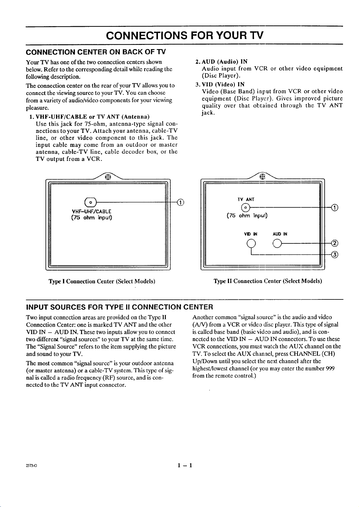
CONNECTION CENTER ON BACK OF TV
Your TV has one of the two connection centers shown
below. Refer to the corresponding detail while reading the
following description.
The connection center on the rear of your TV allows you to
connect the 'viewing source to your TV. You can choose
from a variel_ of audio/video components for your viewing
pleasure.
1. VHF-UHF/CABLE or TV ANT (Antenna)
Use this jack for 75-ohm, antenna-type signal con-
nections to your TV. Attach your antenna, cable-TV
line, or other video component to this jack. The
input cable may come from an outdoor or master
antenna, cable-TV line, cable decoder box, or the
TV output from a VCR.
2. AUD (Audio) IN
Audio input from VCR or other video equipment
(Disc Player).
3. VID (Video) IN
Video (Base Band) input from VCR or other video
equipment (Disc Player). Gives improved picture
quality ,over that oE,tained through the TV ANT
jack.
(S)
VHF-UHF/CABLE
(75 ohm inpuf)
Type I Connection Center (Select Models)
INPUT SOURCES FOR TYPE II CONNECTION CENTER
Two input connection areas are provided on the Type II
Connection Center: one is marked TV ANT and the other
VID IN - AUD IN. These two inputs allow you to connect
two different "signal sources" to your TV at the same time.
The "Signal Source" refers to the item supplying the picture
and sound to your TV.
The most common "signal source" is your outdoor antenna
(or master antenna) or a cable-TV system. This type of sig-
nal is called a radio frequency (RF) source, and is con-
nected to the TV ANT input connector.
Q
Another common "signal source" is the audio and video
(A/V) from a VCR or video disc player. Th!tstype of signal
is called base.,band (basic video and audio), and is con-
nected to the VID IN - AUD IN connectors. To use these
VCR connections, you must watch the AUX channel on the
TV. To select the AUX charLael, press CHANNEL (CH)
Up/Down until you select the next channel ;ffter the
highest/lowest channel (or you may enter the number 999
from the remote ca)ntrol.)
TV ANT
@
(75 ohm Input)
VID IN AUD IN
? o
Type. 11Connection Center (Select Models)
(9
®
®
zs73-o 1 --1
CONNECTIONS FOR YOUR "i%r
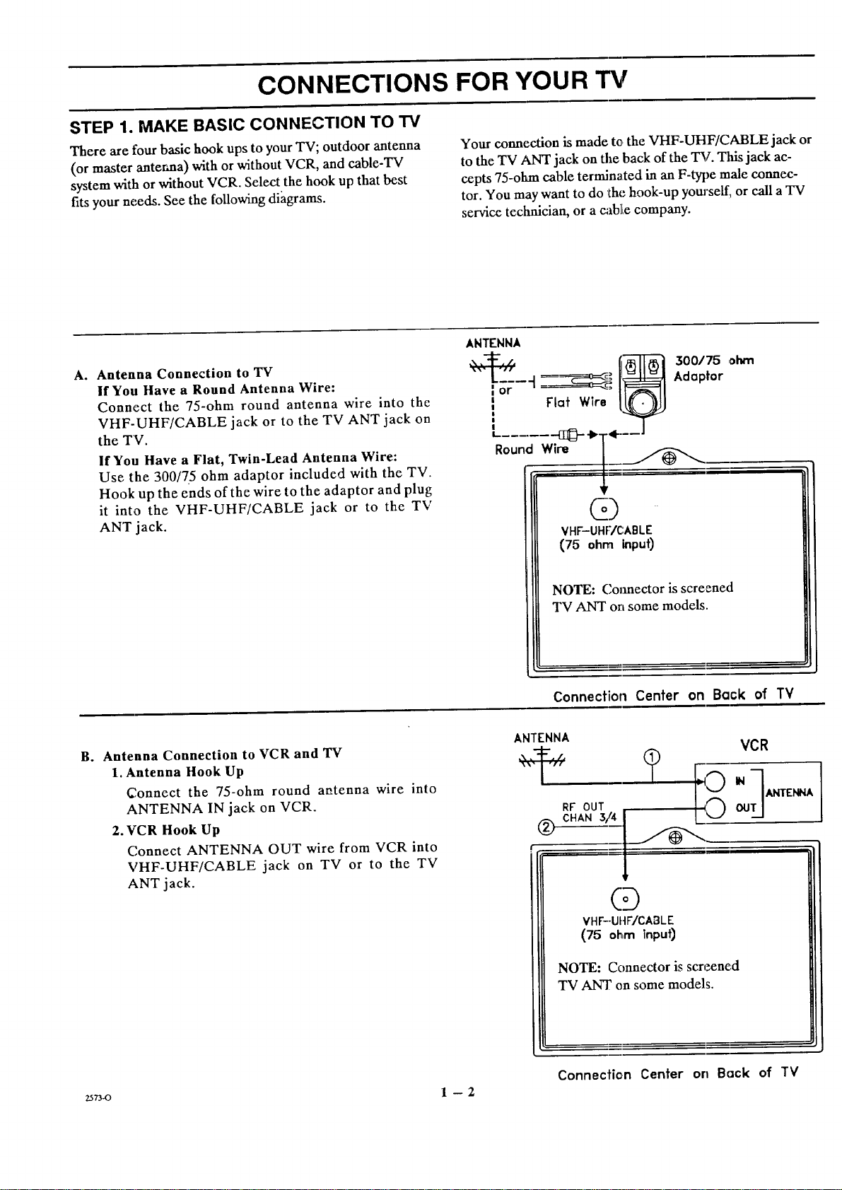
STEP 1. MAKE BASIC CONNECTION TO TV
There are four basic hook ups to your TV; outdoor antenna
(or master antenna) with or without VCR, and cable-TV
system with or without VCR. Select the hook up that best
fits your needs. See the following diagrams.
A° Antenna Connection to TV
If You Have a Round Antenna Wire:
Connect the 75-ohm round antenna wire into the
VHF-UHF/CABLE jack or to the TV ANT jack on
the TV.
If You Have a Flat, Twin-Lead Antenna Wire:
Use the 300/75 ohm adaptor included with the TV.
Hook up the ends of the wire to the adaptor and plug
it into the VHF-UHF/CABLE jack or to the TV
ANT jack.
Your connection is made to,the VHF-UHF/CABLE jack or
to the TV ANT jack on the back of the TV. Tlfis jack ac-
cepts 75-ohan cable terminated in an F-type male connec-
tor. You may want to do the hook-up yourself, or call a TV
service technician, or a cablie company.
ANTENNA
--4 _= II_lJ=_l Adaptor
=or " _: I1=_==11
i Flat Wlre I_
k...... _.bT÷__J
Round Wire [___ ,,
+
@)
VHF-UHF/C:ABLE
(75 ohm input)
B° Antenna Connection to VCR and 'IV
1. Antenna Hook Up
Connect the 75-ohm round aatenna wire into
ANTENNA IN jack on VCR.
2.VCR Hook Up
Connect ANTENNA OUT wire from VCR into
VHF-UHF/CABLE jack on TV or to the TV
ANT jack.
NOTE: Connector is screened
TV ANT on some models.
Connection Center on Back of TV
ANTENNA
t
RF OUT
CHAN3/4
®
VHF--UIIFICABLE
(75 ohm input)
NOTE: Connector is screened
TV ANT on some models.
? I
(D
VCR
z_7_o 1 --2
Connecfie,n Center on Back of TV
CONNECTIONS FOR YOUR TV
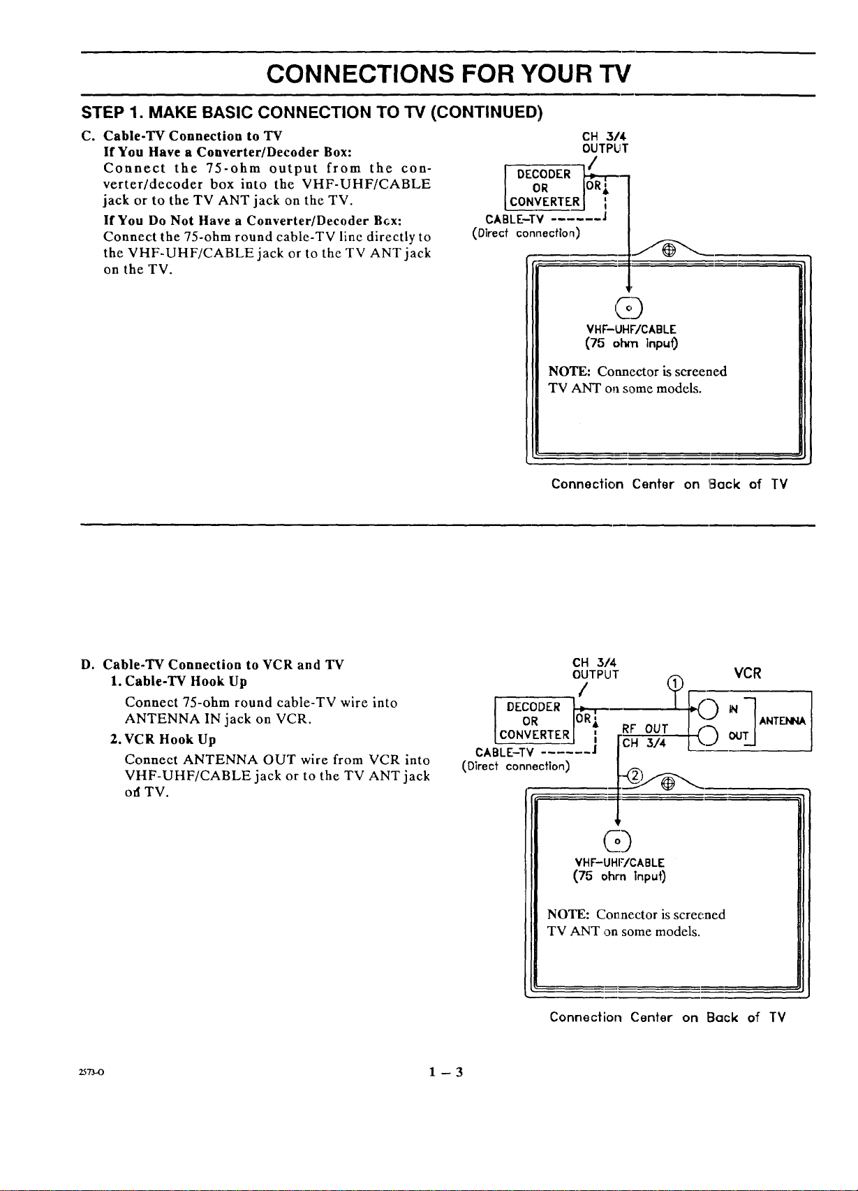
STEP 1. MAKE BASIC CONNECTION TO TV (CONTINUED)
C. Cable-TV Connection to TV
If You Have a Converter/Decoder Box:
Connect the 75-ohm output from the con-
verter/decoder box into the VHF-UHF/CABLE
jack or to the TV ANT jack on the TV.
If You Do Not Have a Converter/Decoder B6x"
Connect the 75-ohm round cable-TV line directly to
the VHF-UHF/CABLE jack or to the TV ANT jack
on the TV.
CONVERTER
CABLE-TV ]
(Direct connection)
CH 3/4
OUTPUT
DECODEROR _-
VHF-UHWCABLE
(75 o_ ]npu0
NOTE: Connector is screened
TVANT on some models.
D. Cable-TV Connection to VCR and TV
I. Cable-TV Hook Up
Connect 75-ohm round cable-TV wire into
ANTENNA IN jack on VCR.
2.VCR Hook Up
Connect ANTENNA OUT wire from VCR into
VHF-UHF/CABLE jack or to the TV ANT jack
off TV.
Connection Center on IE]ock of TV
CH 3/4
OUTPUT VCR
DECODER _ N
CONVF_.RTERJ [ RF OUT
CABLE-TV
(Direct connection)
VHF-UHF/CABLE
(75 ohm Input)
ANTENNA
CH 3/4 OO
Q
_7_o 1 --3
NOTE: Connector is screened
TV ANT on some models.
Connection Center on Back of TV
CONNECTIONS FOR YOUR TV
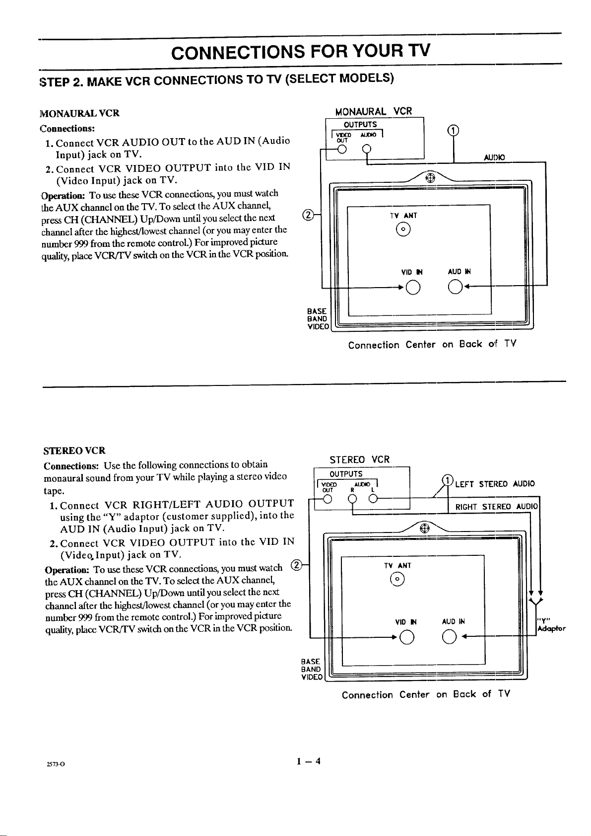
STEP 2. MAKE VCR CONNECTIONS TO TV (SELECT MODELS)
MONAURAL VCR
Connections:
1. Connect VCR AUDIO OUT to the AUD IN (Audio
Input) jack on TV.
2. Connect VCR VIDEO OUTPUT into the VID IN
(Video Input) jack on TV.
,Operation: To use these VCR connections, you must watch
the AUX channel on the TV. To select theAUX channel,
press CH (CHANNEL) Up/Do_ until you select the next
channel after the highest/lowest channel (or you may enter the
number 999 from the remote control.) For improved picture
quality, place VCR/rV switch on the VCR in the VCR position.
Q-
BASE
BANE
VIDEO
MONAURAL VCR
OUTPUTS
v_o _ol
OUT
AUDIO
TV ANT
@
VID IN AUD IN
:© ©:
Connection Center on Back o,F TV
STEREO VC R
Connections: Use the following connections to obtain
monaural sound from your TV while playing a stereo video
tape.
1. Connect VCR RIGHT/LEFT AUDIO OUTPUT
using the "Y" adaptor (customer supplied), into the
AUD IN (Audio Input) jack on TV.
2. Connect VCR VIDEO OUTPUT into the VID IN
(Video. Input) jack on TV.
Operation: 'Touse these VCR connections, you must watch
the AUX channel on the TV. To select the AUX channel,
press CH (CHANNEL) Up/Down until you select the next
channel after the highestBowest channel (or you may enter the
number 999 from the remote control.) For improved picture
quality, place VCR/FV switch on the VCR in the VCR position.
STEREO VCR
OUTPUTS
II',,_ _ l
I out _ L
BASE
BAND
VIDEO
Connection Center on Bock of TV
__/_LEFT STEREO AUDIO
-- |RIGHT STEREO AUDIO
TV ANT
@
VlO IN AUD IN
:©
2sTJ_o 1 -- 4
THE FIRST TIME YOU OPERATE YOUR TV
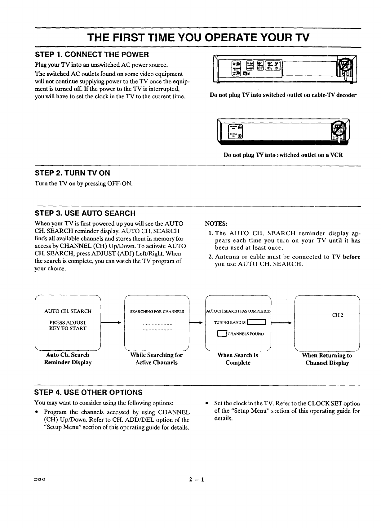
STEP 1. CONNECT THE POWER
Plug your "IV into an unswitched AC power source.
The switched AC outlets found on some video equipment
will not continue supplying power to the TV once the equip-
ment is turned off. If the power to the TV isinterrupted,
you will have to set the clock in the TV to the current time.
STEP 2. TURN TV ON
Turn the TV on by pressing OFF-ON.
STEP 3. USE AUTO SEARCH
When your TV is first powered up you will see the AUTO
CH. SEARCH reminder display. AUTO CH. SEARCH
finds all available channels and stores them in memory for
access by CHANNEL (CH) Up/Down. To activate AUTO
CH. SEARCH, press ADJUST (ADJ) Left/Right. When
the search is complete, you can watch the TV program of
your choi_.
i ®
Do not plug TV into switched outlet on cable-TV decoder
Do not plug TV into .,;witched outlel_on a VCR
NOTES:
1. The AUTO CH. SEARCH reminder display ap-
pears each time you turn on your TV until it has
been u,;ed at:least once.
2. Antenna or cable must be connected to TV before
you use AUTO CH. SEARCH.
_=
AUTO CH. SEARCH
PRESS ADJUST
KEY TO START
Auto Ch. Search While Searching for When Search is
Reminder Display Active Channels Complete
SEARCHING FOR CHANNELS
_,lYrO CH. SEARCH HAS COMPLEIEE,
TUNING BAND IS
[-_ CHANNEL_ FOUND
STEP 4. USE OTHER OPTIONS
You may want to consider using the following options:
• Program the channels accessed by using CHANNEL
(CH) Up/Down. Refer to CH. ADD/DEL option of the
"Setup Menu" section of this operating guide for details.
25rvo 2 -- 1
Set the clock in the TV. Refer to the CLOCK SET option
of the "Setup Menu" section of this operating guide for
details.
CH2
.J
When Returning to
Channel Display
OPERATING YOUR TV
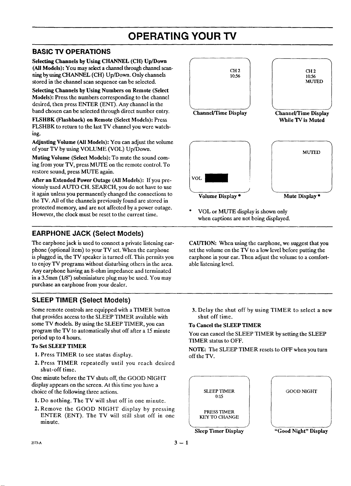
BASIC TV OPERATIONS
Selecting Channels by Using CHANNEL (CH) Up/Down
(All Models): You may select a channel through channel scan-
ning by using CHANNEL (CH) Up/Down. Only channels
stored in the channel scan sequence can be selected.
Selecting Channels by Using Numbers on Remote (Select
Models): Press the numbers corresponding to the channel
desired, then press ENTER (ENT). Any channel in the
band chosen can be selected through direct number entry.
FLSHBK (Flashback) on Remote (Select Models): Press
FLSHBK to return to the last TV channel you were watch-
C'H2
10".56
Channel/Time Display
CH2
10:56
MLrI_D
J
ChanvLelFI'imeDisplay
Whil,e TV is Muted
Adjusting Volume (All Models): You can adjust the volume
of your TV by using VOLUME (VOL) Up/Down.
Muting Volume (Select Models): To mute the sound com-
ing from your TV, press MUTE on the remote control. To
restore sound, press MUTE again.
After an Extended Power Outage (All Models): If you pre-
viously used AUTO CH. SEARCH, you do not have to use
it again unless you permanently changed the connections to
the TV. All of the channels previously found are stored in
protected memory, and are not affected by a power outage.
However, the clock must be reset to the current time.
EARPHONE JACK (Select Models)
The earphone jack isused to connect a private listening ear-
phone (optional item) to your TV set. When the earphone
is plugged in, the TV speaker is turned off. This permits you
to enjoy TV programs without disturbing others in the area.
Any earphone having an 8-ohrn impedance and terminated
in a 35ram (1/8") subminiature plug may be used. You may
purchase an earphone from your dealer.
SLEEP TIMER (Select Models)
Some remote controls are equipped with a TIMER button
that provides access to the SLEEP TIMER available with
some TV faodels. By using the SLEEP TIMER, you can
program the TV to automatically shut off after a 15 minute
period up to 4 hours.
To Set SLEEP TIMER
1. Press TIMER to see status display.
2. Press TIMER repeatedly until you reach desired
shut-off time.
One minute before the TV shuts off, the GOOD NIGHT
display appears on the screen. At this time you have a
choice of the following three actions.
1. Do nothing. The TV will shut off in one minute.
2. Remove the GOOD NIGHT display by pressing
ENTER (ENT). The TV will still shut off in one
minute.
#
MUTED
:VOL
\
Volume Display *
* VOL or MUTE display is shown only
when captions are not being displayed.
CAUTION: When using the earphone, we suggest that you
set the volume on the TV to a low level before putting the
earphone ill your ear. Then adjust the volume to a comfort-
able listening level.
3. Delay the shut off by using TIMER to select a new
shut off time.
To Cancel the SLEEP TIMER
You can cancel the SLEEP TIMER by setting the SLEEP
TIMER status to OFF.
NOTE: The SLEEP TIMFR resets to OFF when you turn
off the TV.
SLEEP TIMER
0:15
PRESS TIMER
KEY TO CHANGE
Sleep Timer Display
Mute ]Display *
GOOD NIGHT
"Good Night" Display
z573-^ 3 -- 1
 Loading...