

Zenith SL2518RK, SLS8753Y, SLS2506M, SLS8937Y, SLS7253S Owner’s Manual
...
OPERATING GUIDE & WARFq',ANTY
recycled paper
5ENTI:
MTS Stereo Color TV
with Remote Control
and Closed Captions
Return the Product Registration
Card, and your TV could be free!
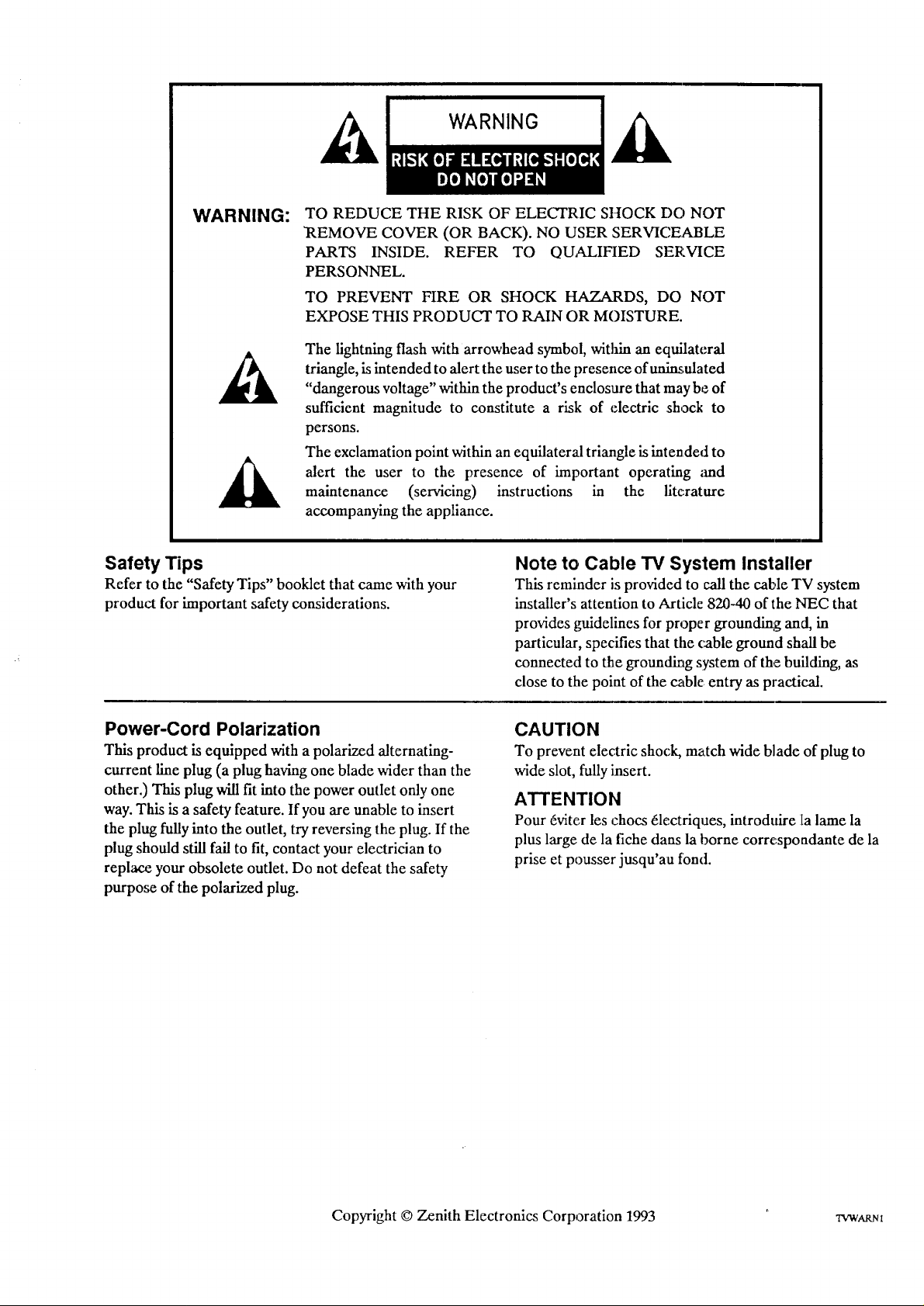
WARNING:
TO REDUCE THE RISK OF ELECTRIC SHOCK DO NOT
REMOVE COVER (OR BACK). NO USER SERVICEABLE
PARTS INSIDE. REFER TO QUALIFIED SERVICE
PERSONNEL.
TO PREVENT FIRE OR SHOCK HAZARDS, DO NOT
EXPOSE THIS PRODUCT TO RAIN OR MOISTURE.
The lightning flash with arrowhead symbol, witlfin an equilateral
triangle, is intended to alert the user to the presence of unius.nlated
"dangerous voltage" within the product's enclosure that may be of
sufficient magnitude to constitute a risk of electric shock to
persons.
The exclamation point within an equilateral triangle isintended to
alert the user to the presence of important operating ;rod
maintenance (servicing) instructions in the literature
accompanying the appliance.
Safety Tips
Refer to the "Safety Tips" booklet that came with your
product for important safety considerations.
Power-Cord Polarization
This product is equipped with a polarized alternating-
current line plug (a plug having one blade wider than the
other.) This plug will fit into the power outlet only one
way. This is a safety feature. If you are unable to insert
the plug fully into the outlet, try reversing the plug. If the
plug should still fail to fit, contact your electrician to
replace your obsolete outlet. Do not defeat the safety
purpo_ of the polarized plug.
Note to Cable TV System Installer
This reminder is provided to call the cable TV system
installer's attention to Article 820-40 of the NEC that
provides guidelines for proper grounding and, in
particular, specifies that the cable ground shall be
connected to the grounding system of the building, as
close to the point of the cable entry as practical.
CAUTION
To prevent electric shock, match wide blade of plug to
wide slot, fully insert.
ATTENTION
Pour 6viter les chocs 6lectriques, introduire la lame la
plus large de la fiche dans la borne correspondante de la
prise et pousser jusqu'au fond.
Copyright © Zenith Electronics Corporation 1993 rVWARm

CONTENTS
iNTRODUCTION
Welcome ........................................... ii
]Installation Considerations ........................... il
CONNECTIONS FOR YOUR TV
Connection Center on Back of'IV ................... 1-1
Input Sources for Your TV ......................... 1-1
:Stereo Audio Output .............................. 1-1
Step 1. Make Basic Connection to TV ................ 1-2
Step 2. Make VCR Connections to TV ............... 1-4
Step 3. Make Stereo Audio Connection
to Audio Amplifier ............................ 1-5
THE FIRST TIME YOU OPERATE YOUR TV
Step 1. Connect the Power .......................... 2-1
Step 2. Turn "IV On ............................... 2-1
Step 3. Use Auto Ch. (Channel) Search ............... 2-1
Step 4. Use Other Options .......................... 2-1
GETrING TO KNOW YOUR TV
Horizontal Control Panels .......................... 3-1
Vertical Control Panel ............................. 3-2
REMOTE CONTROL MODEL SC3390
Operation ........................................ 4-1
Preparation for Use ............................... 4-2
Installing Batteries ................................ 4-2
REMOTE CONTROL MODEL SC3820
TV Operations .................................... 5-I
VCR Operations .................................. 5-2
TV and VCR Operational Notes .................... 5-3
Preparation for Use ............................... 5-3
Installing Batteries ................................ 5-3
OPERATING YOUR TV
Basic TV Operations ............................... 6-1
Sleep Timer . ..................................... 6-1
SETUP MENU
Auto Ch. (Channel) Search ......................... 8-1
Ch. (Channel) Add/Del ............................. 8-2
Ch. (Channel) Labels (Some Models) ................. 8-2
Tuning Band ....................................... 8-3
Auto Fine Tune ..................................... 8-3
Clock Set ........................................... 8-4
Captions ........................................... 8-4
Ch. (Channel) Background ........................... 8-5
AUDIO MENU
General Information ................................. 9-1
Bass ............................................... 9-1
Treble .............................................. 9-1
Balance ............................................ 9-1
Audio .............................................. 9-1
Audio Selection Considerations ...................... 9-2
VIDEO MENU
Contrast ......................................... 10-1
Brightness ....................................... 10-1
Color ........................................... 10-1
Tint ............................................. 10-1
Sharpness ....................................... 10-1
Picture Pref. (Preference) .......................... 10-1
MAINTENANCE AND TROUBLESHOOTING
Caring for Your TV ................................ 11-1
Extended Absence ................................. 11-1
TV Picture Interference ............................ 11-1
Before Calling for Service ........................... 11-2
VCR Operational Mode Charts ..................... 11-3
Product Registration Card
Recommended Accessories for Your Television
Your Zenith Warranty
ON-SCREEN MENUS
Available Menus .................................. 7-1
Summary of Menu Items ........................... 7-1
Basic Menu Operations ............................ 7-2
USING YOUR OPERATING GUIDE
This operating guide describes a family of TV models. Some models have features
that are not provided on other models. Different control panels and remote controls
may be used from model-to-model. Refer to the applicable; sections of this operating
guide for the features and items provided with your TV.
2s89-o i
INTRODUCTION
'WELCOME
Welcome into the family of Zenith Color Television owners.
This guide provides instxuctions on how to operate your
new TV. It is supplemented by a booklet containing Safety
Tips. We urge you to read these publications carefully so
that you will receive fur[ enjoyment from your new Zenith
TV for many years to come.
Your new Zenith TV has been designed and built to give
you the very best in quality, features and performance.
There are many regional Zenith distributors and thousands
of distributor-approved Zenith service centers throughout
the U.S. and Canada who can attend promptly and effective-
ly to ordinary service needs.
If you should have an unusual performance or service problem
that cannot be satisfactorily resolved by your distributor-
approved Zenith service center, contact the regional Zenith
distributor in your area, or write:
Zenith Electronics Corporation
Customer Service Department
1900 N. Austin Avenue
Chicago, IUinois 60639-5079
Telephone: (312) 745-5152
Mon-Fri, 8:00 a.m. - 4:30 p.m. Central Time
Send the model number, serial namber, and date of pur-
chase or original installation, Mth a full explianation of the
problem and the service history. We will welcome the op-
portunity to look into your specilic question or problem and
to be of assistance in resolving it promptly.
The model and serial numbers of:yournewTV are located on
the back of the TV cabinet. For your future ca)nvenience and
protection, we suggest that you record these numbers here:
Model No.
Serial No.
INSTALLATION CONSIDERATIONS
Before you install your TV...
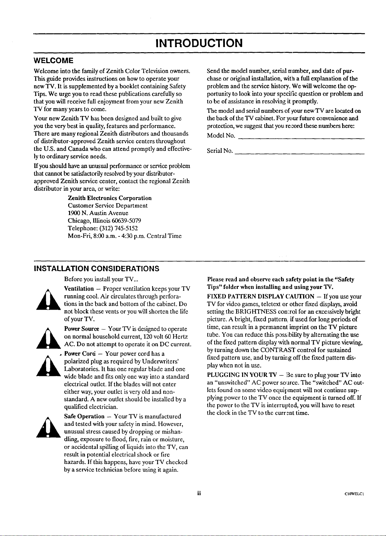
Ventilation - Proper ventilation keeps your TV
running cool. Air circulates through perfora-
tions in the back and bottom of the cabinet. Do
not block these vents or you will shorten the life
of your TV.
Power Source - Your TV is designed to operate
on normal household current, 120 volt 60 Hertz
AC. Do not attempt to operate it on DC current.
Power Cord - Your power cord has a
polarized plug as required by Underwriters'
Laboratories. It has one regular blade and one
wide blade and fits only one way into a standard
electrical ,outlet. If the blades will not enter
either way, your outlet is very old and non-
standard. A new outlet should be installed by a
qualified electrician.
Safe Operation - Your TV is manufactured
and tested with your safety in mind. However,
unusual stress caused by dropping or mishan-
dling, exposure to flood, fire, rain or moisture,
or accidental spilling of liquids into the TV, can
result in potential electrical shock or fire
hazards. If this happens, have your TV checked
by a service technician before using it again.
Please read and observe each safety point in the "Safety
Tips" folder when installing: and using your TV.
FIXED PATIERN DISPLAY CAUTION .- If you use your
TV for video games, teletext or other fixed displays, avoid
setting the BRIG HTNESS comrol for an excessively bright
picture. A bright, fixed pattern, if used for long periods of
time, can result in a permanent imprint on the TV picture
tube. You can reduce this poss!ibility by alternating the use
of the fixed pattern display with normal TV picture viewing,
by turning down the CONTRAST control for sustained
fixed pattern use, and by turnirtg off the f_ced pattern dis-
play when not in use.
PLUGGING IN YOUR TV - ]Besure to plug your TV into
an "unswitched" AC power source. The "switched" AC out-
lets found on some video ectuipment will not continue sup-
plying power to the TV once the equipment is turned off. If
the power to the TV is interrupted, you will have to reset
the clock in the TV to the curr=nt time.
ii C10WELC1

CONNECT!ONS FOR YOUR TV
CONNECTION CENTER ON BACK OF TV z.
The connection center on the rear of your TV allows you to
_mnect two viewing sources to your TV, and an external
stereo sound amplifier, if desired. You can choose from a
variety of audio/video components for your viewing
pleasure. The diagram below lists the use of each jack on
the connection center.
1. VHF-UHF/CABLE
Use this jack for 75-ohm, antenna-type signal con-
nection to your TV. Attach your antenna, cable-TV
line, or other video component to this jack. The
input cable may come from an outdoor or master
antenna, cable-TV line, cable-TV decoder box, or
the RF output from a VCR.
3. AUX (Auxiliary) INPUT AUDIO RIGHT and LEFT
5. VARIABLE AUDIO OUTPUT RIGHT and LEFT
AUX (Auxiliary) INPUT VIDEO
Video (Base Band) input: from VCR or other video
equipment (Disc Player). Gives improved picture
quality performance over that obtained through the
VHF-UHF/CABLE jack.
Stereo audio input from VCR or other video equip-
ment (Disc Player).
4. SPEAKER EXT/INT Switch
EXT position: TV's speakers are off.
INT position: TV's speakers are on.
Stereo audio output for customer's attdio amplifier.
This output is always prose:at regardle.ss of the posi-
tion of the SPEAKER swit :h.
RIGHT LEFT
O O,-
VARIABLE AUDIO
OUTPUT
_ VH F.-UHFICABLE
INPUT SOURCES FOR YOUR TV
Your TV has two input connection areas: one is marked
VHF-UHF/CABLE axtdthe other AUX INPUT VIDEO -
AUX INPUT AUDIO RIGHT and LEFT. These two in-
puts allow you to connect two different "signal sources" to
your TV at lhe same thne. The "Signal Source" refers to the
item supplying the picture and sound to your TV.
The most common "signal source" is your outdoor antenna
(or master antenna) or a cable-TV system. This type of sig-
nal is called a radio frequency (RF) source, and is con-
nected to the VHF-UItF/CABLE input connector.
SPEAKER
AUX INPUT
_DEO AUDIO
OOO
_IL RIGHT LEFT
Another common "signal source" is the audio and video
(A/V) from a VCR or video disc player. This _pe ofsignal is
called base band (basic video and audio), and is connected to
the AUX INPUT VIDEO - AUX INPUT AUDIO RIGHT
and LEFT connectors. To use th_se VCR connexXions, you
must watch the AUX channel on the TV. To select the AUX
channel, press CHANNEL (CH)Up/Down until you select
the next channel after the highest/lowest clammel, or enter the
number 999 from the remote control, or press SOURCE on
the remote control if available.
STEREO AUDIO OUTPUT
Your TV provides stereo audio output suitable for connec-
tion to your stereo souaad system. Connect the VARIABLE
AUDIO OUTPUT RIGHT and LEFT jacks to an unused
_o 1 --1
input on your stereo amplifier. You may cxmtinue to listen
to the sound coming from the TV's speakers, or switch off
the TV's speakers as desired.

CONNECTIONS FOR YOUR TV
STEP 1. MAKE BASIC CONNECTION TO TV
There are four basic hook ups to your TV; outdoor antenna
(or master antenna) with or without VCR, and cable-TV
system with or without VCR. Select the hook up that best
fits your needs. See the following diagrams.
Ao Antenna Connection to TV
If You Have a Round Antenna Wire:
Connect the 75-ohm round antenna wire into the
VHF-UHF/CABLE jack on the TV.
If You Have a Flat, Twin-Lead Antenna Wire:
Use the 300/75-ohm adaptor included with the TV.
Hook up the ends of the wire to the adaptor and plug
it into the VHF-UHF/CABLE jack.
Your connection is made to the VHF-UHF/CABLE jack
on the back of the TV. This jack accepts 75--otml cable ter-
minated in an F-type male connector. You may want to do
the hook-up yourself, or call a TV service technician, or a
cable company.
Antenna
I or Rat Wire
I
I
Round Wire
Adaptor
_ 00175ohm
RIGHT LEFT
0 0
VARI/MII.EAUDIO
OUIPUT
SPEAKER
0 VHF-UHF/CABLE AUXINPUT
_DEO AtJOIO
0 () 0
I_GHT
B, Antenna Connection to VCR and TV
1. Antenna Hook Up
Connect 75-ohm round antenna wire into
ANTENNA IN jack on VCR.
2.VCR Hook Up
Connect ANTENNA OUT wire from VCR into
tire VHF-UHF/CABLE jack on TV.
Antenna
?
Connection Center on Back of IV
VCR
?
CHAN 314
0 VHF-U:HF/CABLE AUX INPUT
000
Connec'tlon Center on Back of IV
RIGHT LEFT
0 0
VARIABLE AUDIO
OUIPUT
SPEAd<ER
RIGHT LEFT
z589-o 1 -- 2
CONNECTIONS FOR YOUR TV
STEP 1. MAKE BASIC CONNECTION TO TV (CONTINUED)
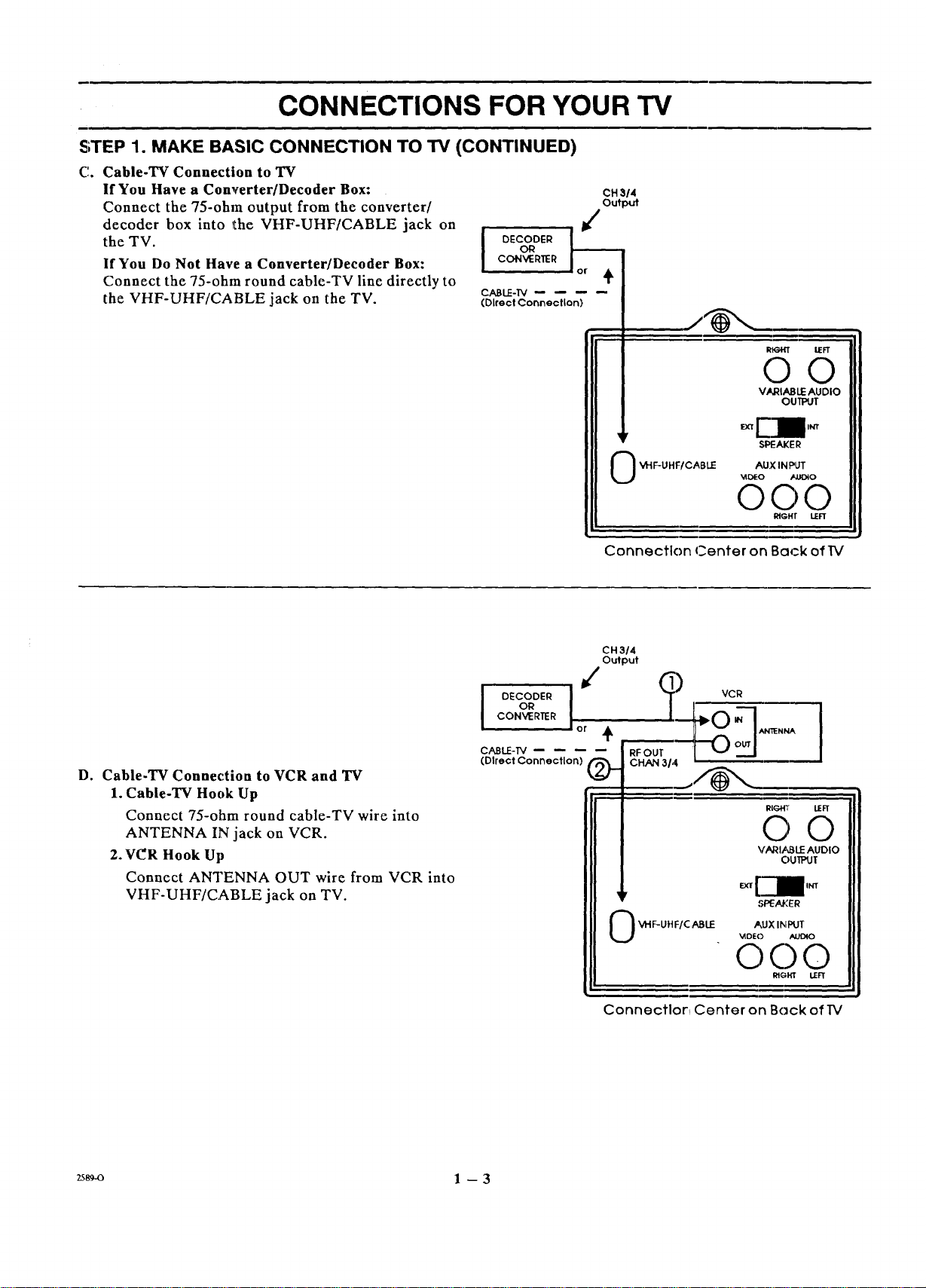
C. Cable-TV Connection to TV
If You Have a Converter/Decoder Box:
Connect the 75-ohm output from the converter/
decoder box into the VHF-UHF/CABLE jack on
the TV.
If You Do Not Have a Converter/Decoder Box:
Connect thc 75-ohm round cablc-TV line directly to
the VHF-UHF/CABLE jack on the TV.
OR
I DECODER
CON_RER
CABLE-I'V
(Direct Connection)
CH 314
Output
I_=HT IrFT
0 0
VARIABLE AUDIO
OUTPUT
D, Cable-TV Connection to VCR and "IV
1. Cable-TV Hook Up
Connect 75-ohm round cablc-TV wire into
ANTENNA IN jack on VCR.
2. VC_RHook Up
Connect ANTENNA OUT wire from VCR into
VHF-UHF/CABLE jack on TV.
_y
0 _'IF-UHF/CABLE
_DtEO _&lOIO
©©©
Connection Center on Back of'W
CH3/4
Output
io cooE,! ?vc
CONVERTER
or + ANlIENNA
CABLE-T',/
(Dlrect Connection) _.
RFOUT
CHAIN 31,4
SPEAKER
AUX IN PLJT
RIGHT LEFT
RIGId" IFFf
O O
VARIt_LE AUDIO
OUIPUT
,'_:_AI,'ER
2589-o 1 -- 3
0 VHF-UHF/C ABLE AUX INPUT
. _DEO AUDIO
C)O 0
RIGI_ LEFT
Connection Center on Back of TV
CONNECTIONS FOR YOUR TV
STEP 2. MAKE VCR CONNECTIONS TO TV
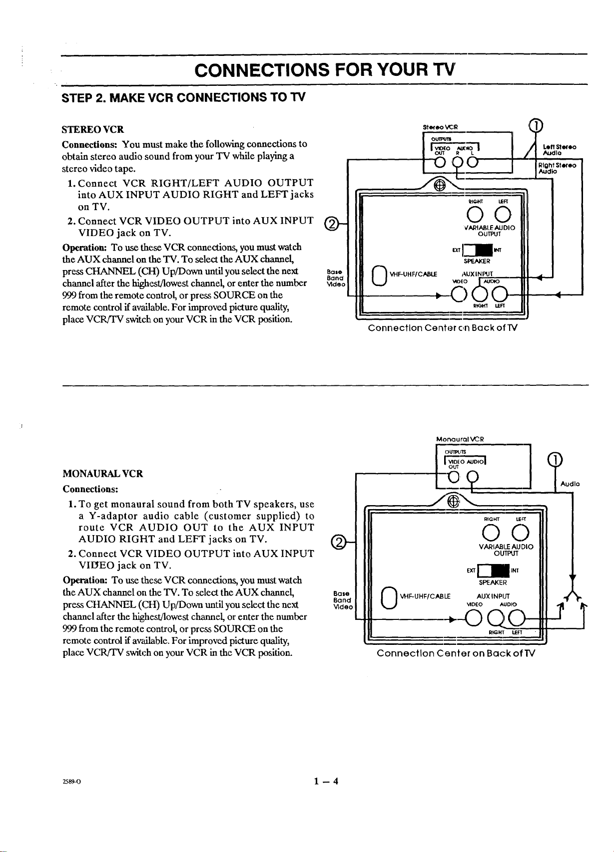
STEREO VCR
Connections: You must make the following connections to
obtain stereo audio sound from your TV while playing a
stereo video tape.
1. Connect VCP, P,IGHT/LEFT AUDIO OUTPUT
into AUX INPUT AUDIO RIGHT and LEFT jacks
on TV.
2. Connect VCP, VIDEO OUTPUT into AUX INPUT
VIDEO jack on TV.
Operation: To use these VCR connections, you must watch
the AUX channel on the TV. To select the AUX channel,
press CHANNEL (CH) Up/Down until you select the next
channel after the high,t/lowest channel, or enter the number
999 from the remote control, or press SOURCE on the
remote control if available. For improved picture quality,
place VCR/TV switch on your VCR in the VCR position.
0-
BQIO
Band
_deo
Stereo VC,'R
VARIABLE AUDIO J
OUTPUT J
i-11- I
VHF-UHF/CABLE AUXINPUT _ I
0
RIGHT L£FI
Connection Center on Back ofIV
MONAURALVCR
Connections:
1. To get monaural sound from both TV speakers, use
a Y-adaptor audio cable (customer supplied) to
route VCR AUDIO OUT to the AUX INPUT
AUDIO RIGHT and LEFT jacks on TV.
2. Connect VCP, VIDEO OUTPUT into AUX INPUT
VIEIEO jack on TV.
Operation: To use these VCR connections, you must watch
the AUX channel on the TV. To select the AUX channel,
press CHANNEL (CH) Up/Down until you select the next
channel ".ffterthe highestAowest channel, or enter the number
999 from the remote control, or press SOURCE on the
remote control if awdlable. For improved picture quality,
place VCR/TV switch on your VCR in the VCR position.
Base
8end
Video
MonaurQl VCR
()U11_JIS
o .uD,ol
,?
RIGHT LIE_
0 0
VAI_IABI P AU DIO
OUl_n"
SPEAKER
0 _'r'IF-UHF/CAB LE AUX INPUT
Connection Center on Back of IV
VIDEO AUDIO
(]O--
RIGOr t_F'[
(_Audlo
'1 P
zs_-o 1 -- 4

CONNECTIONS FOR YOUR TV
STEP 3. MAKE STEREO AUDIO CONNECTION TO AUDIO AMPLIFIER
Using an External Amplifier with Speakers While the TV's
Speakers are OFF.
1. Make the connections to the external amplifier as
shown in the diagram below.
2. Place the SPEAKER EXT/INT switch on the TV in
the INT position (TV's speakers are ON).
3. Turn the TV ON. Increase the volume level of the
TV until the sound just starts to distort (sound bad).
4. Place the SPEAKER EXT/INT switch on the TV in
the EXT position (TV's speakers are OFF).
5. Turn the external audio amplifier ON. Adjust the
volume level of tlhe audio amplifier for the highest
level you will need for your listening pleasure.
6, Adjust the volume level of the TV for the normal
listening level as heard through the speakers of your
audio amplifier.
7, You can now use the VOLUME (VOL) control on
the TV or on tZhe remote control to adjust the
volume of the speakers of your audio amplifier.
Using an External Amplifier with Speakers While the TV's
Speakers are ON.
1. Make the connections to the external amplifier as
shown in the diagram below.
2. Place the SPEAKER EXT/INT switch on the TV in
the INT position (TV's speakers are ON).
3. Turn the TV ON. Increase the volume level of the
TV until the sound just starts to distort (sound bad).
4. Turn the external aud!io amplifier ,ONAdjust the
volume level of the audio amplifier for the highest
level you will need for your listening pleasure.
5. Adjust the volume level of the TV for the normal
listening level as heard through the speakers of the
TV.
6. You can now use the VOLUME (VOL) control on
the TV or on the remote control to adjust the
volume of both the TV':; speakers and the audio
amplifier's speakers.
NOTE: If the volume of the internal TV speakers is set too
low, you may heat undesirable noises through the speakers
connected to your audio amplit_er.
Panel on Bockof
Slereo Amplifier
AUX_
_ TO DQ_RNAL
RIGHT LO
O---
VARIABLEAUDIO
OUTPUT
SF_AKER
VHF-UHF/CABLE
AUX INPUT
MIDC-O AUDIO
©0©
RIGHT LEFT
Connection Center on Back ofIV
2589-o 1 - 5
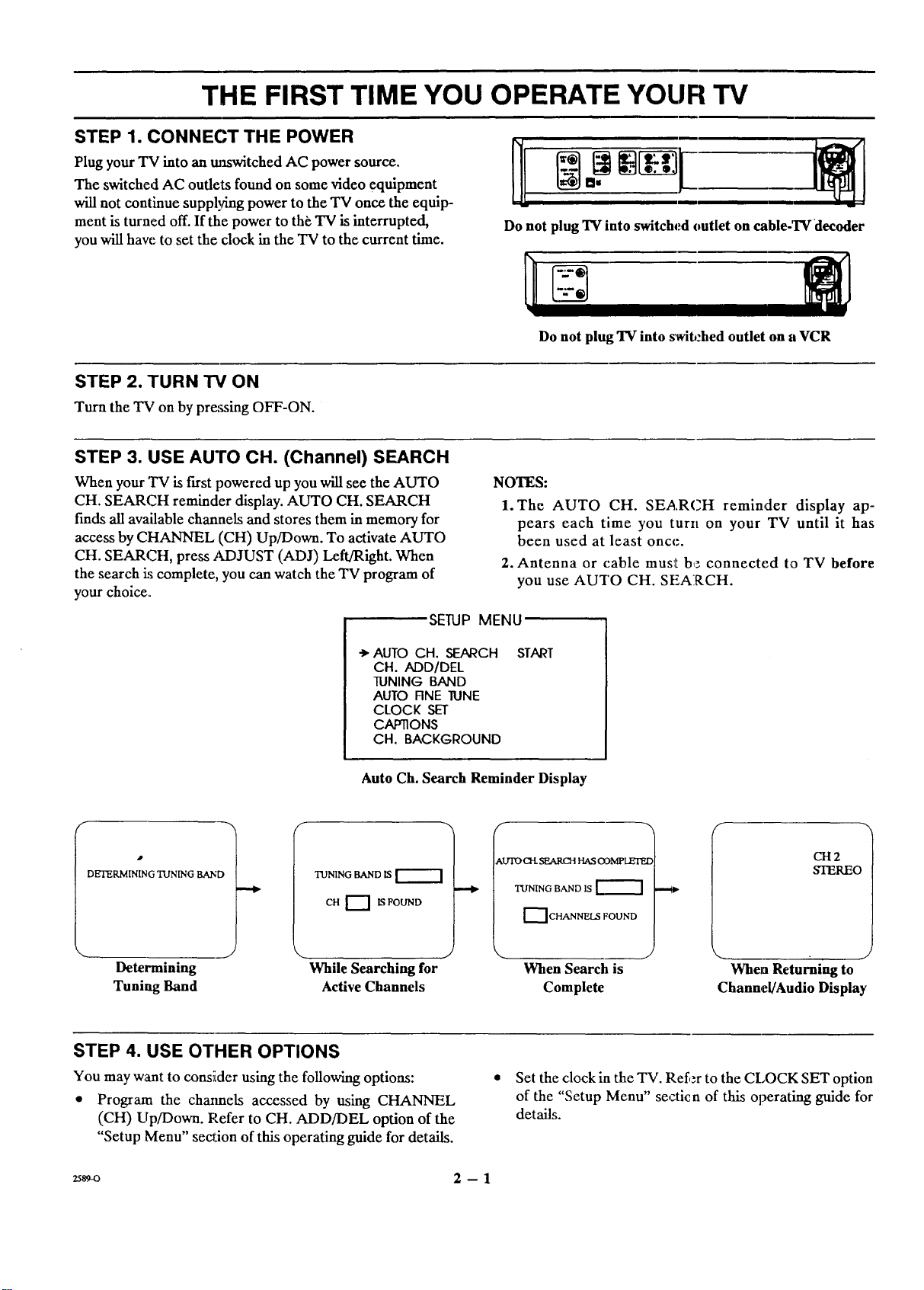
THE FIRST TIME YOU OPERATE YOUR TV
STEP 1. CONNECT THE POWER
h,
Plug your TV into an maswitched AC power source. ][[
The switched AC oudets found on some video equipment
will not continue suppl_hng power to the TV once the equip-
ment is turned off. If the power to the, TV is interrupted,
Do not plug TV into switched outlet on cable-'rv decoder
you will have to set the clock in the TV to the current time.
STEP 2. TURN TV ON
Turn the TV on by pressing OFF-ON.
STEP 3. USE AUTO CH. (Channel) SEARCH
When your TV is first powered up you will see the AUTO
CH. SEARCH reminder display. AUTO CH. SEARCH
finds all available channels and stores them in memory for
access by CHANNEL (CH) Up/Down. To activate AUTO
CH. SEARCH, press ADJUST (ADJ) Left/Right. When
the search is complete, you can watch the TV program of
your choice.
SETUP MENU
NOTES:
1. The AUTO CH. SEARCH reminder display ap-
2. Antenna or cable mus_t b_: connected to TV before
Do not plug TV into _wil_:hed outlet on a VCR
pears each time you turn on your TV until it has
been used at least once.
you use AUTO CH. SEARCH.
->"AUTO CH. SEARCH
CH. ADD/DEL
TUNING BAND
AUTO RNE TONE
CLOCK SET
CAP_ONS
CH. BACKGROUND
Auto Ch. Search Reminder Display
DETERMINING TUNING BAND
TUNING BAND IS
CH f--'] IS FOUND
Determining While Searching for
Tuning Band Active Channels
STEP 4. USE OTHER OPTIONS
You may want to consider using the following options:
• Program the cha_mels accessed by using CHANNEL
(CH) Up/Down. Pefer to CH. ADD/DEL option of the
"Setup Menu" section of this operating guide for details.
START
AUTO Ot. SEARCH HAS ODMPLEI'F_
---4P
q'X/NING BAND IS
r_ CHANNELS FOUND
\
When Search is When Returning to
Complete Channel/Audio Display
• Set the clock in the TV. Refer to the CLOCK SET option
of the "Setup Menu" secticn of this operating guide for
details.
CH2
STEREO
2s89-o 2 -- 1

GETTING TO KNOW YOUR TV
HORIZONTAL CONTROL PANELS
The following description applies to models having a
horizontal control panel.
q • ADJUSTI, SELECT MENU A'_A_)LL.IMEv .AC.HA,NNELv
i
Front Panel Controls
1. ENTER (ENT)
Press to see the Channel/Time display, or to removc
any on-screen display or menu.
2. ADJUST (ADJ) Left/Right or "_/l_
Presg during on-screen menu operation to see infor-
mation/status ,display for selected option. Press
again to adjust the selected menu option.
3. SELECT (SEL)
Press during on-screen menu operations to select a
menu option.
4. MENU
Press once to see a menu. Press repeatedly to se-
quence through the available menus.
EN'I_R O R:/C N
Full Size Control Panels
Mini Control Panel
I ll=l
L_._J
E_
I"
IIsELII l !_=
5. VOLUME (VOL) Up/Down
Press to increase or decrease the ,;ound level.
6. CHANNEL (CH) Up/Down
Press to select channe'ts higher or lower than the chan-
nels being viewed. You can add channels to or delete
channels from the :;canning sequence stored in
memory. See CH. ADD/DEL option of the "Setup
Menu" section of thiis operating guide for channel
programming inform_ktion.
7. OFF-ON
Press to turn TV power ON or OFF.
8. Remote Control Detect_r Window
Point the remote control towards this window to
operate the TV.
_mm
El l
z589-o 3 -- 1
 Loading...