

Zenith SLS2728RK, SL2726EW, SL2722RK, SL2567W Owner’s Manual
OPERATING GUIDE _, WARRANTY
recycled paper
SENT_ 2
MTS Stereo Color TV
with Remote Control
and Closed Captions
Return the Product Registration
Card, and your TV could be free!
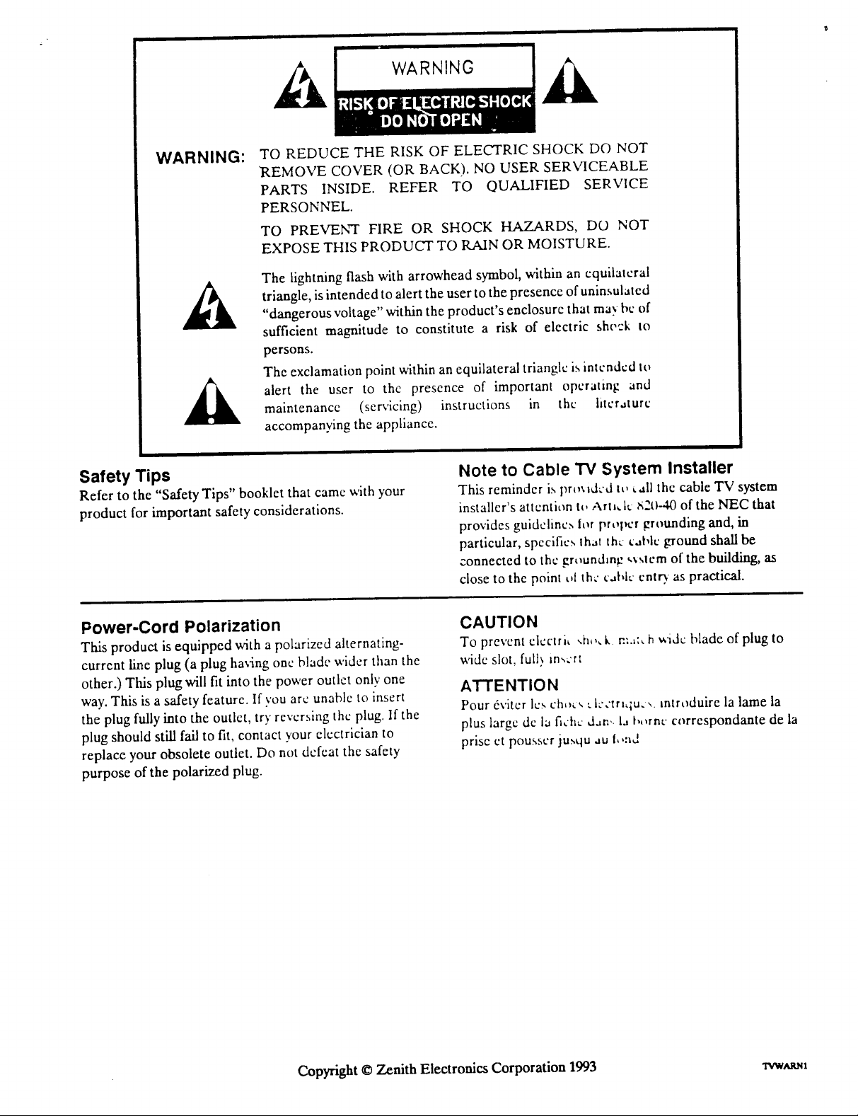
WARNING:
TO REDUCE THE RISK OF ELECTRIC SHOCK DO NOT
REMOVE COVER (OR BACK). NO USER SERVICEABLE
PARTS INSIDE. REFER TO QUALIFIED SERVICE
PERSONNEL.
TO PREVENT FIRE OR SHOCK HAZARDS, DO NOT
EXPOSE THIS PRODUCT TO RAIN OR MOISTURE.
The lightning flash with arrowhead symbol, within an equilateral
triangle, isintended to alert the user to the presence of uninsulated
"dangerous voltage" within the product's enclosure that may bc of
sufficient magnitude to constitute a risk of electric shc,'.'k to
persons.
The exclamation point within an equilateral triangle is intended to
alert the user to thc presence of important operating and
maintenancc (servicing) instructions in the literature
accompanying the appliance.
Safety Tips
Refer to the "Safety Tips" booklet that camc with your
product for important safety considerations.
Power-Cord Polarization
This product is equipped with a polarized alternating-
current line plug (a plug having one blade wider than the
other.) This plug will fit into the power outlet only one
way. This is a safety featurc. If you arc unable to insert
the plug fully into the outlet, try reversing the plug. If the
plug should still fail to fit, contact your electrician to
replace your obsolete outlet. Do not defeat thc safety
purpose of the polarized plug.
Note to Cable TV System Installer
This reminder is pr_=dcd t_, Lall the cable TV system
installer's attention tt, Artl,l_ S2t)-40 of the NEC that
provides guidclinc._ ior proper grounding and, in
particular, specifics Ih;.=lthe ta|,lc ground shall be
connected to the gr_undm_ _stem of the building, as
close to the point t_lth," c-,bk' cntr)as practical.
CAUTION
To prevent elcctri_ ,ia,,, k v.:.,:_h wide blade of plug to
wide slot, fult_ m_crt
ATTENTION
Pour 6viter Ic_ ch,,_ __k'crr,_u.,, mtroduire la lame la
plus large dc la fich_ dan.. la t,,,rnt" corrcspondante de la
prise et pousscr jusqu au l,,:sd
Copyright © Zenith Electronics Corporation 1993 'rvwtams
CONTENTS
INTRODUCTION
Welcome ........................................... ii
Installation Considerations ........................... ii
CONNECTIONS FOR YOUR TV
Connection Center on Back of TV ................... 1-1
Input Sources for Your TV ......................... 1-1
Stereo Audio Output .............................. 1-1
Step 1. Make Basic Connection to TV ................ 1-2
Step 2. Make VCR Connections to TV ............... 1-4
Step 3. Make Stereo Audio Connection
to Audio Amplifier ............................ 1-5
THE FIRST TIME YOU OPERATE YOUR
Step 1. Connect the Power .......................... 2-1
Step 2. Turn TV On ............................... 2-1
Step 3. Use Auto Ch. (Channel) Search ............... 2-1
Step 4. Use Other Options .......................... 2-1
GETTING TO KNOW YOUR TV
Horizontal Control Panel ........................... 3-1
Vertical Control Panel ............................. 3-2
GETrlNG TO KNOW YOUR REMOTE CONTROL
Introduction ...................................... 4-1
Choosing Operating Mode ......................... 4-1
TV Operations .................................... 4-2
VCR Operations .................................. 4-3
Cable-TV Operations .............................. 4-4
Preparation for Use ............................... 4-5
Installing Batteries ................................ 4-5
OPERATING YOUR 'IV
Basic TV Operations .............................. 5-1
Sleep Timer ...................................... 5-1
ON-SCREEN MENUS
Available Menus .................................. 6-1
Summary of Menu Items ........................... 6-1
Basic Menu Operations ............................ 6-2
SETUP MENU
Auto Ch. (Channel) Search ......................... 7-1
Ch. (Channel) Add/Del ............................. 7-2
Ch. (Channel) Labels (Some Models) ................. 7-2
Tuning Band ...................................... 7-3
Auto Fine Tune ................................... 7-3
Clock Set ......................................... 7-4
Captions ......................................... 7-4
Ch. (Channel) Background .......................... 7-5
AUDIO MENU
General Information ............................... 8-1
Bass ............................................. 8-1
Treble ........................................... 8-1
Balance .......................................... 8-1
Audio ............................................ 8-1
SEQ (Spatial Equalization) ......................... 8-1
Audio Selection Considerations ...................... 8-2
VIDEO MENU
Contrast .......................................... 9-1
Brightness ........................................ 9-1
Color ............................................ 9-1
Tint .............................................. 9-1
Sharpness ........................................ 9-1
Picture Pref. (Preference) ........................... 9-1
PROGRAMMING THE REMOTE CONTROL
Introduction ..................................... 10-1
TV, VCR and Cable-TV Operating Codes ........... 10-2
MAINTENANCE AND TROUBLESHOOTING
Caring for Your TV ............................... 11-1
Extended Absence ................................ 11-1
TV Picture Interference ........................... 11-1
Before Calling for Service .......................... 11-2
vCR Operational Mode Charts .................... 11-3
Product Registration Card
Recommended Accessories for Your Television
USING YOUR OPERATING GUIDE
This operating guide describes a family of TV models. Some models have features
that are not provided on other models. Different control panels and remote controls
may be used from model-to-model. Refer to the applicable sections of this operating
guide for the features and items provided with your TV.
_7.o i
Your Zenith Warranty

INTRODUCTION
WELCOME
Welcome into the family of Zenith Color Television owners.
This guide provides instructions on how to operate your
new TV. It is supplemented by a booklet containing Safety
Tips. We urge you to read these publications carefully so
that you will receive full enjoyment from your new Zenith
TV for many years to come.
Your new Zenith TV has been designed and built to give
you the very best in quality, features and performance.
There are many regional Zenith distributors and thousands
of distributor-approved Zenith service centers throughout
the U.S. and Canada who can attend promptly and effective-
ly to ordinary service needs.
If you should have an unusual performance or service problem
that cannot be satisfactorily resolved by your distributor-
approved Zenith service center, contact the regional Zenith
distributor in your area, or write:
Zenith Electronics Corporation
Customer Service Department
1900 N. Austin Avenue
Chicago, Illinois 60639-5079
Telephone: (312) 745-5152
Mon-Fri, 8:00 a.m. - 4:30 p.m. Central Time
Send the model number, serial number, and date of pur-
chase or original installation, with a full explanation of the
problem and the service history. We will welcome the op-
portunity to look into your specific question or problem and
to be of assistance in resolving it promptly.
The model and serial numbers of your new TV are located on
the back of the TV cabinet. For your future convenience and
protection, we suggest that you record these numbers here:
Model No.
Serial No.
INSTALLATION CONSIDERATIONS
Before you install your TV...
Ventilation - Proper ventilation keeps your TV
running cool. Air circulates through perfora-
tions in the back and bottom of the cabinct. Do
not block these vents or you will shortcn the life
of your TV.
Power Source - Your TV is designed to operate
on normal household current, 120 volt 60 Hertz
AC. Do not attempt to operate it on DC current.
Power Cord - Your power cord has a
polarized plug as required by Underwriters'
Laboratories. It has one regular blade and one
wide blade and fits only one way into a standard
electrical outlet. If the blades will not enter
either way, your outlet is very old and non-
standard. A new outlet should be installed by a
qualified electrician.
Safe Operation - Your TV is manufactured
and tested with your safety in mind. However,
unusual stress caused by dropping or mishan-
dling, exposure to flood, fire, rain or moisture,
or accidental spilling of liquids into the TV, can
result in potential electrical shock or fire
hazards. If this happens, have your TV checked
by a service technician before using it again.
Please read and observe each safety point in the "Safety
Tips" folder when installing and using your TV.
FIXED PA'IWERN DISPLAY CAUTION - If you use your
TV for video games, teletext or other fixed displays, avoid
setting the BRIGHTNESS control for an excessively bright
picture. A bright, fixed pattern, if used for long periods of
time, can result in a permanent imprint on the TV picture
tube. You can reduce this possibility by alternating the use
of the fixed pattern display with normal TV picture viewing,
by turning down the CONTRAST control for sustained
fLxedpattern use, and by turning off the fixed pattern dis-
play when not in use.
PLUGGING IN YOUR 'IN - Be sure to plug your TV into
an "unswitched" AC power source. The "switched" AC out-
lets found on some video equipment will not continue sup-
plying power to the TV once the equipment is turned off. If
the power to the TV is interrupted, you will have to reset
the clock inthe TV to the current time.
ii ctowm.m
CONNECTIONS FOR YOUR TV
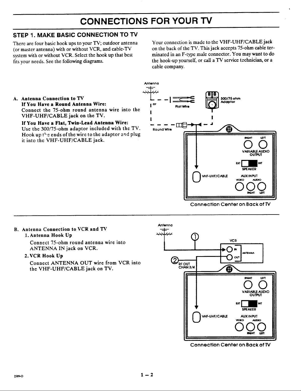
STEP 1. MAKE BASIC CONNECTION TO "IV
There are four basic hook ups to your TV; outdoor antenna
(or master antenna) with or without VCR, and cable-TV
system with or without VCR. Select the hook up that best
fits your needs. See the following diagrams.
Antenna Connection to "IV
A,
If You Have a Round Antenna Wire:
Connect the 75-ohm round antenna wire into the
VHF-UHF/CABLE jack on the TV.
If You Have a Flat, Twin-Lead Antenna Wire:
Use the 300/75-ohm adaptor included with the TV.
Hook up tt'e ends of the wire to the adaptor and plug
it into the VHF-UHF/CABLE jack.
Your connection is made to the VHF-UHF/CABLE jack
on the back of the TV. This jack accepts 75-ohm cable ter-
minated in an F-type male connector. You may want to do
the hook-up yourself, or call a TV service technician, or a
cable company.
Antenna
i or Rot Wlre
I
I
Round Wire
_ 00175ohm
A_loptor
OO
VARIABLE AUDIO
OUTPUT
LEFT
B° Antenna Connection to VCR and "IV
1. Antenna Hook Up
Connect 75-ohm round antenna wire into
ANTENNA IN jack on VCR.
2. VCR Hook Up
Connect ANTENNA OUT wire from VCR into
the VHF-UHF/CABLE jack on TV.
_y
VHF-UHF/CABLE AUX INPUT
0
VIDEO _0
000
Connection Center on Back ofTV
CHAN 3/4
©
I
lr
_I"IF-UHF/CABLE AUX INPUT
0
[LOIN
I--O
VCR
m
m
VARIABLE AUDIO
_D_EO AgOIO
000
SPEAKER
R_I_ LER
ANllENNA
LEFT
OO
OUlPUT
SPEAKER
25s_o 1 -- 2
Connection Center on Back of IV
CONNECTIONS FOR YOUR "iV
STEP 1. MAKE BASIC CONNECTION TO TV (CONTINUED)
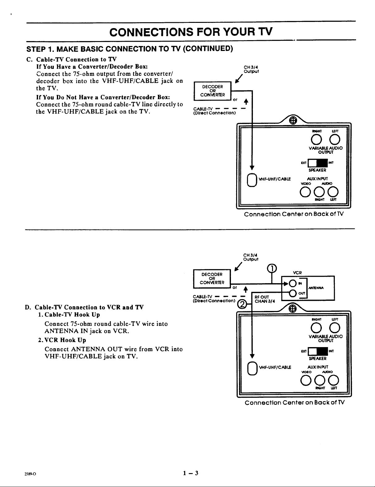
C. Cable-TV Connection to TV
If You Have a Converter/Decoder Box:
Connect the 7S-ohm output from the converter/
decoder box into the VHF-UHF/CABLE jack on
the TV.
If You Do Not Have a Converter/Decoder Box:
Connect the 7S-ohm round cable-TV line directly to
the VHF-UHF/CABLE jack on the TV.
OR
CONVERTER
DECODER
CABLE-TV
(Dlrect Connection)
CH 314
Output
LEFT
OO
VARIABLE AUDIO
OUlPUT
Do Cable-TV Connection to VCR and TV
1. Cable-TV Hook Up
Connect 75-ohm round cable-TV wire into
ANTENNA IN jack on VCR.
2.VCR Hook Up
Connect ANTENNA OUT wire from VCR into
VHF-UHF/CABLE jack on TV.
OR
CONVERTER
DECODER
CABLE-TV
(Dlrect Connection)
i,
VHF-UHF/CABLE AUX INPUT
©
SPEAKER
_DIEO AUOIO
000
RIGHT LEFT
i
Connection Center on Back ofI_/
CH 314
Output
VCR
or
RFOUT
CHAN 314
I
OO
VARIABLE AUDIO
OUlPUT
SPEAKER
VHF-UHF/CABLE
AUX IN PUT
_oEO ALI_O
000
LEFT
2_s9-o 1 - 3
Connection Center on Back of TV
CONNECTIONS FOR YOUR TV
STEP 2. MAKE VCR CONNECTIONS TO "IV
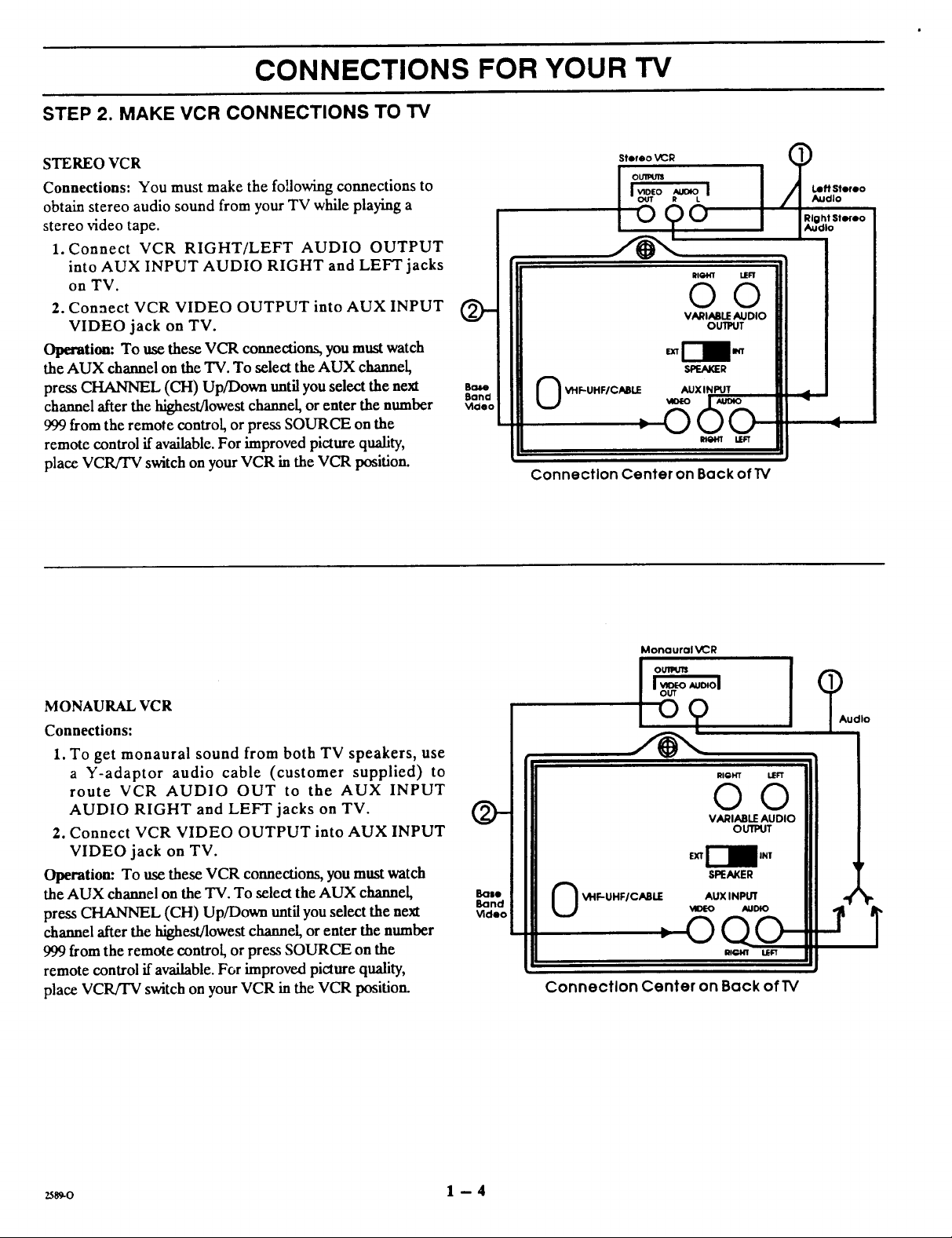
STEREO VCR
Connections: You must make the foUowing connections to
obtain stereo audio sound from your TV while playing a
stereo video tape.
1. Connect VCR RIGHT/LEFT AUDIO OUTPUT
into AUX INPUT AUDIO RIGHT and LEFT jacks
on TV.
2. Connect VCR VIDEO OUTPUT into AUX INPUT
VIDEO jack on TV.
Operation: To use these VCR connections, you must watch
the AUX channel on the TV. To select the AUX channel,
press CHANNEL (CH) Up/Down until you select the neJa
channel after the highest/lowest channel, or enter the number
999 from the remote control, or press SOURCE on the
remote control if available. For improved picture quality,
place VCR/TV switch on your VCR in the VCR position.
Ballo
Bana
Vlaeo
Stereo VCR Q
oumu11
I,=o=, I
i OOO i JR""IghtStereo
RIGM,n" MEn'
©©
VARIABLE AUDIO
OUTPUT
SPF-AKER
VHF-UHF/CABLE AUX INPUT
Iv
Connection Center on Back of IV
MONAURAL VCR
Connections:
1. To get monaural sound from both TV speakers, use
a Y-adaptor audio cable (customer supplied) to
route VCR AUDIO OUT to the AUX INPUT
AUDIO RIGHT and LEFT jacks on TV.
2. Connect VCR VIDEO OUTPUT into AUX INPUT
VIDEO jack on TV.
Operation: To use these VCR connections, you must watch
the AUX channel on the TV. To select the AUX channel,
press CHANNEL (CH) Up/Down until you select the next
channel after the highest/lowest channel, or enter the number
999 from the remote control, or press SOURCE on the
remote control if available. For improved picture quality,
place VCR/TV switch on your VCR in the VCR position.
@-
[kllle
Band
Video
Monaural VCR
RIGHT LEFT
O0
VARIABLE AUDIO
OUTPUT
SPEAKER
VHF-UHFICABLE AUX INPUT
0
_ID£O AUDIO
OQO
RIGHT LER
Connection Center on Back of TV
_[_Audlo
.2
I
r
4
zs_-o 1 -- 4
CONNECTIONS FOR YOUR TV
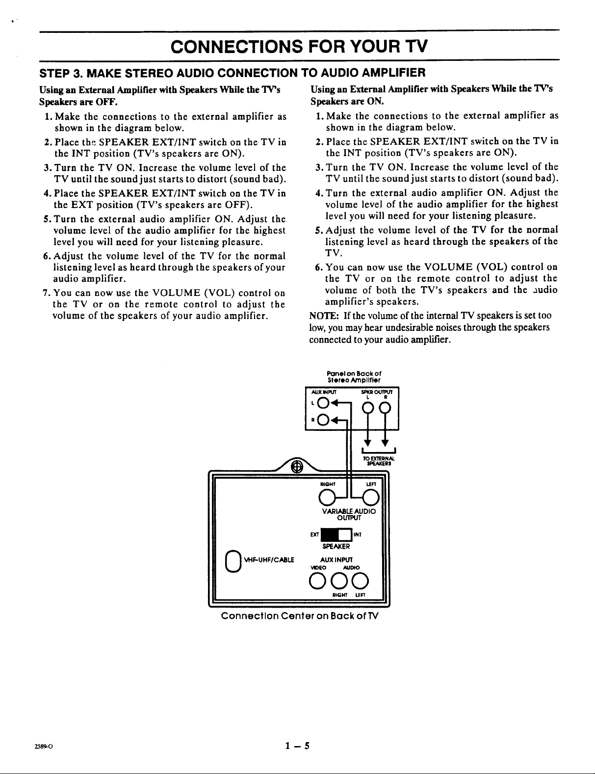
STEP 3. MAKE STEREO AUDIO CONNECTION TO AUDIO AMPLIFIER
Using an External Amplifier with Speakers While the TV's
Speakers are OFF.
1. Make the connections to the external amplifier as
shown in the diagram below.
2. Place the SPEAKER EXT/INT switch on the TV in
the INT position (TV's speakers arc ON).
3. Turn the TV ON. Increase the volume level of the
TV until the sound just starts to distort (sound bad).
4. Place the SPEAKER EXT/INT switch on the TV in
the EXT position (TV's speakers arc OFF).
5. Turn the external audio amplifier ON. Adjust the
volume level of the audio amplifier for the highest
level you will nccd for your listening pleasure.
6. Adjust the volume level of the TV for the normal
listening level as heard through the speakers of your
audio amplifier.
7. You can now use the VOLUME (VOL) control on
the TV or on the remote control to adjust the
volume of the speakers of your audio amplifier.
Using an External Amplifier with Speakers While the TV's
Speakers are ON.
1. Make the connections to the external amplifier as
shown in the diagram below.
2. Place the SPEAKER EXT/INT switch on the TV in
the INT position (TV's speakers are ON).
3. Turn the TV ON. Increase the volume level of the
TV until the sound just starts to distort (sound bad).
4. Turn the external audio amplifier ON. Adjust the
volume level of the audio amplifier for the highest
level you will need for your listening pleasure.
5. Adjust the volume level of the TV for the normal
listening level as heard through the speakers of the
TV.
6. You can now use the VOLUME (VOL) control on
the TV or on the remote control to adjust the
volume of both the TV's speakers and the audio
amplifier's speakers.
NOTE: If the volume of the internal TV speakers is set too
low, you may hear undesirable noises through the speakers
connected to your audio amplifier.
Panel on Back of
Stereo Amtollfler
??
SPEAKER
0 _I"IF-UHF/CABLE
Connection Center on Back of TV
AUX INPUT
_OEO AUDIO
000
RIGHT LEFT
zs_o 1 -- 5
THE FIRST TIME YOU OPERATE YOUR TV
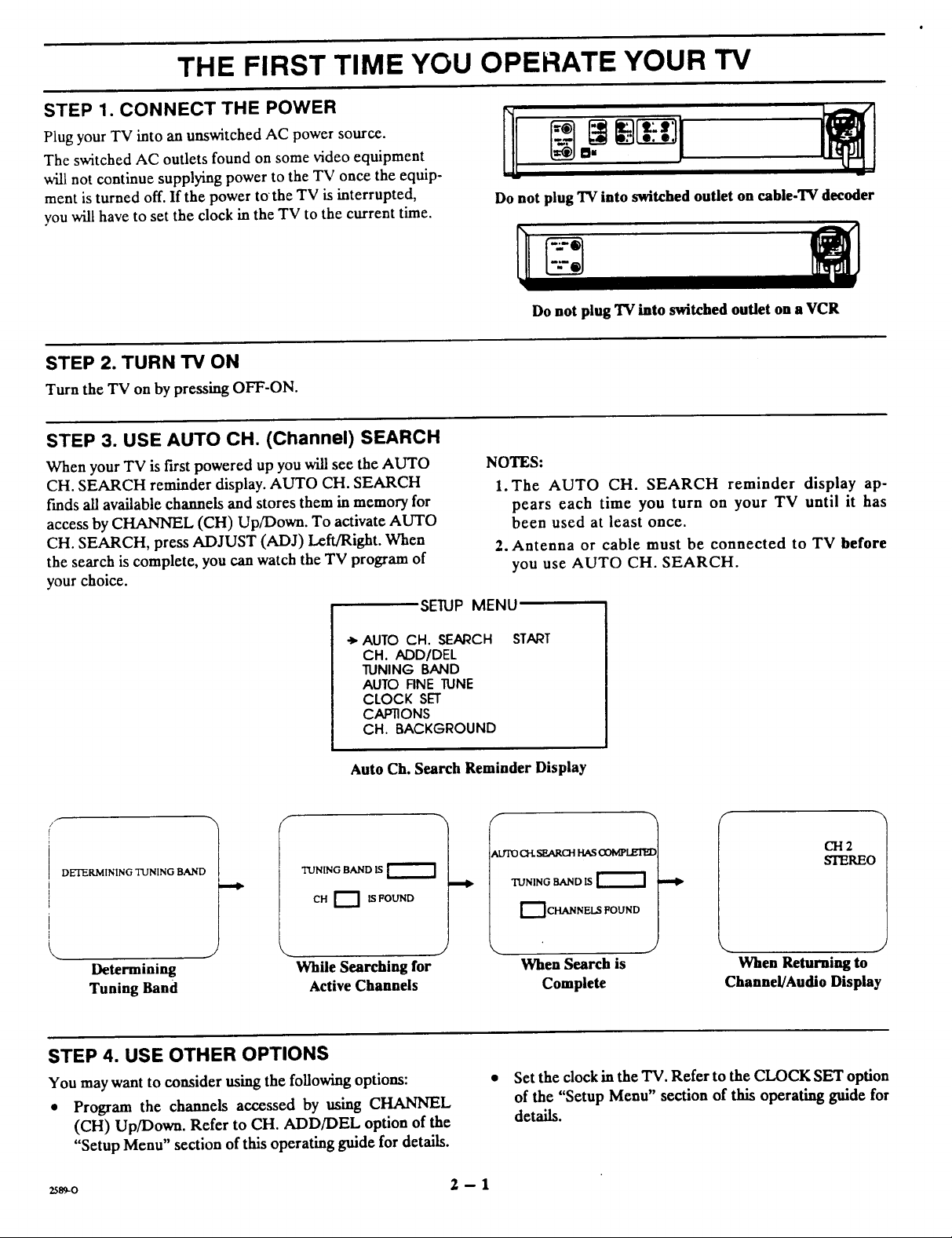
STEP 1. CONNECT THE POWER
Plug your TV into an unswitched AC power source.
The switched AC outlets found on some video equipment
will not continue supplying power to the TV once the equip-
ment is turned off. If the power to the TV is interrupted,
you will have to set the clock in the TV to the current time.
STEP 2. TURN TV ON
Turn the TV on by pressing OFF-ON.
STEP 3. USE AUTO CH. (Channel) SEARCH
When your TV is first powered up you will see the AUTO
CH. SEARCH reminder display. AUTO CH. SEARCH
t'mds all available channels and stores them in memory for
access by CHANNEL (CH) Up/Down. To activate AUTO
CH. SEARCH, press ADJUST (ADJ) Left/Right. When
the search is complete, you can watch the TV program of
your choice.
SETUP MENU
Do not plug TV into switched outlet on cable-TV decoder
Do not plug "IV into switched outlet on a VCR
NOTES:
1. The AUTO CH. SEARCH reminder display ap-
pears each time you turn on your TV until it has
been used at least once.
2. Antenna or cable must be connected to TV before
you use AUTO CH. SEARCH.
• , AUTO CH. SEARCH
CH. ADD/DEL
TUNING BAND
AUTO FINE TUNE
CLOCK SET
CAPTIONS
CH. BACKGROUND
Auto Ch. Search Reminder Display
DETERMINING TUNING BAND
Determining
Tuning Band
TUNING BAND IS
CH _ IS FOUND
While Searching for
Active Channels
STEP 4. USE OTHER OPTIONS
You may want to consider using the following options:
• Program the channels accessed by using CHANNEL
(CH) Up/Down. Refer to CH. ADD/DEL option of the
"Setup Menu" section of this operating guide for details.
START
f
!
_trlD ell. SEARO-I HASO3MPLZI_
TUNING RAND IS
1_ CHANNELS FOUND
CH2
STEREO
When Search is When Returning to
Complete Channel/Audio Display
Set the clock in the TV. Refer to the CLOCK SET option
of the "Setup Menu" section of this operating guide for
details.
2589-o 2 - 1
GETTING TO KNOW YOUR TV
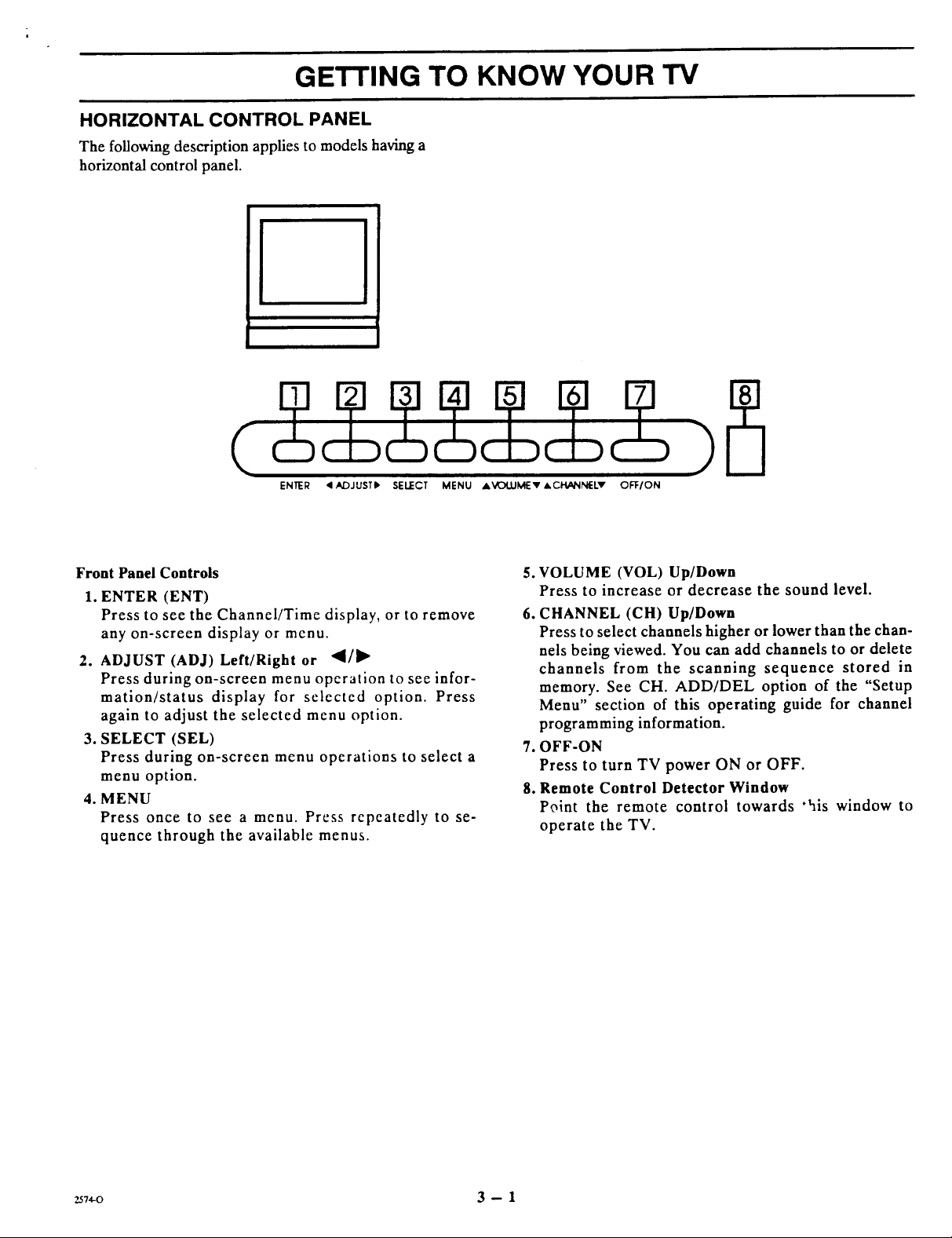
HORIZONTAL CONTROL PANEL
The following description applies to models having a
horizontal control panel.
ENteR < ADJUSTI_ SELECT MENU AVOI.UMEv J, CHANNELv OFFION
Front Panel Controls
1. ENTER (ENT)
Press to see the Channel/Time display, or to remove
any on-screen display or menu.
2. ADJUST (ADJ) Left/Right or _/llP
Press during on-screen menu operation to see infor-
mation/status display for selected option. Press
again to adjust the selected menu option.
3. SELECT (SEL)
Press during on-screen menu operations to select a
menu option.
4. MENU
Press once to see a menu. Press repeatedly to se-
quence through the available menus.
.
VOLUME (VOL) Up/Down
Press to increase or decrease the sound level.
6.
CHANNEL (CH) Up/Down
Press to select channels higher or lower than the chan-
nels being viewed. You can add channels to or delete
channels from the scanning sequence stored in
memory. See CH. ADD/DEL option of the "Setup
Menu" section of this operating guide for channel
programming information.
,
OFF-ON
Press to turn TV power ON or OFF.
Remote Control Detector Window
8.
Point the remote control towards "his window to
operate the TV.
257,0 3 -- 1
GETTING TO KNOW YOUR TV
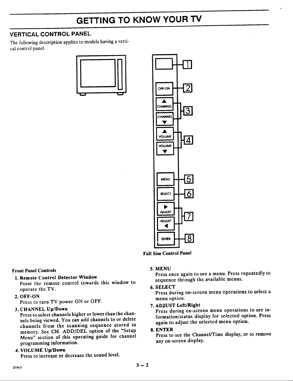
VERTICAL CONTROL PANEL
The following description applies to models having a verti-
cal control panel.
W
Front Panel Controls
1. Remote Control Detector Window
Point the remote control towards this window to
operate the TV.
2. OFF-ON
Press to turn TV power ON or OFF.
3. CHANNEL Up/Down
Press to select channels higher or lower than the chan-
nels being viewed. You can add channels to or delete
channels from the scanning sequence stored in
memory. See CH. ADD/DEL option of the "Setup
Menu" section of this operating guide for channel
programming information.
4. VOLUME Up/Down
Press to increase or decrease the sound level.
257.o 3 -- 2
Full Size Control Panel
5. MENU
Press once again to see a menu. Press repeatedly to
sequence through the available menus.
6. SELECT
Press during on-screen menu operations to select a
menu option.
7. ADJUST Left/Right
Press during on-screen menu operations to see in-
formation/status display for selected option. Press
again to adjust the selected menu option.
8. ENTER
Press to see the Channel/Time display, or to remove
any on-screen display.
 Loading...