

Page 1
- 7 -
1. Application Object
These instructions are applied to all of the PDP monitor, NP00LE.
2. Notes
(1) Because this is not a hot chassis, it is not necessary to use
an isolation transformer. However, the use of isolation
transformer will help protect test instrument.
(2) Adjustment must be done in the correct order.
(3) The adjustment must be performed in the circumstance of
25±5¡C of temperature and 65±10% of relative humidity if
there is no specific designation.
(4) The input voltage of the receiver must keep 110~240V,
50/60Hz in adjusting.
(5) The receiver must be operated for about 15 minutes prior
to the adjustment.
¤ After receiving 100% white pattern(06CH), the receiver
must be operate prior to adjustment.(Or white condition
in HEAT-RUN mode)
¤ŁEnter into HEAT-RUN mode
- Select the HEAT-RUN OFF by pressing ADJ button on
Remote Control for adjustment.
- Press the VOL + button in HEAT-RUN OFF.
(OSD display HEAT-RUN WHITE and screen display
100% full WHITE PATTERN)
¤ØSet is activated HEAT-RUN without SET TOP BOX or
signal generator in this mode.
[ Single color pattern of HEAT-RUN mode uses to check
PANEL.(RED/BLUE/GREEN)
[Caution] If you turn on a still screen more than 20 minutes, a
afterinage may be occur in the black level part of the
screen.
3. POWER PCB Assy Voltage Adjustment
[ Replace PDP Module or Power Board, adjust certainly Power
PCB Assy Voltage.
3-1. Test Equipment
D.M.M 1EA
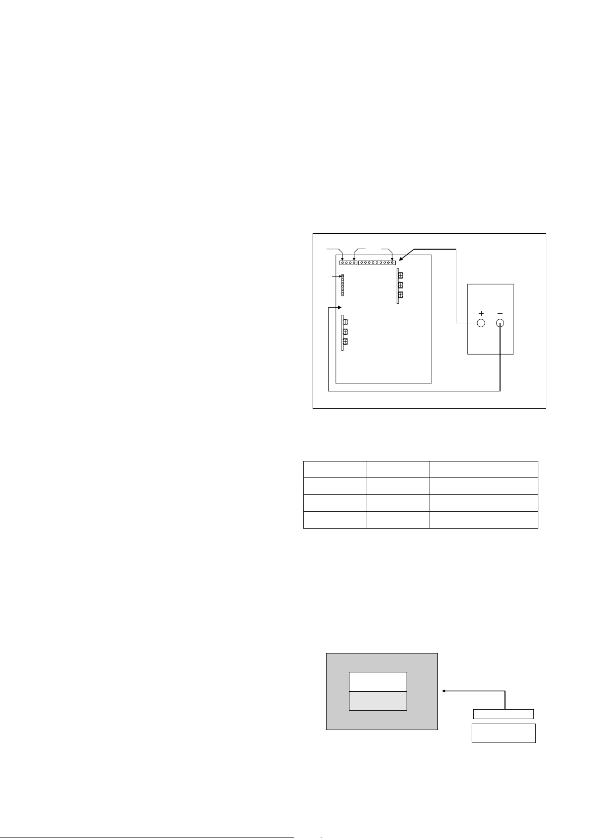
3-2. Connection Diagram for Measuring
Refer to Fig 1.
3-3. Adjustment Method
(1) Va Adjusment(Address Voltage Adjusment)
¤ Connect pin 1 of P814 to (+) jack of D.M.M.
¤ŁAfter turning the VR803(Va Adj), voltage of D.M.M
adjustment as same as Va voltage which on label of
panel right/bottom.(Deviation : ±0.5V)
(2) Vs Adjustment
¤ Connect pin of P803 to (+) jack of D.M.M.
¤ŁAfter turning the VR804(Vs Adj), voltage of D.M.M
adjust as same as Vs voltage which indicated on label
of panel right/bottom.(Deviation : ±0.5V)
(3) VSC Adjustment
¤ Connect pin 4 of P802 to (+) jack of D.M.M.
¤ŁAfter turning the VR806(VSC Adj), voltage of D.M.M
adjust as same as Vs voltage which indicated on label
of panel right/bottom.(Deviation : ±0.5V)
(4) VSETUP Adjustment
¤ Connect pin 1 of P802 to (+) jack of D.M.M.
¤ŁAfter turning the VR805(VSETUP Adj),voltage of D.M.M
adjust as same as Vs voltage which indicated on label
of panel right/bottom.(Deviation : ±0.5V)
4. Adjustment of RGB Cut-off and
White Balance
4-1. Required Equipment
Color analyzer(CA-100 or same production)
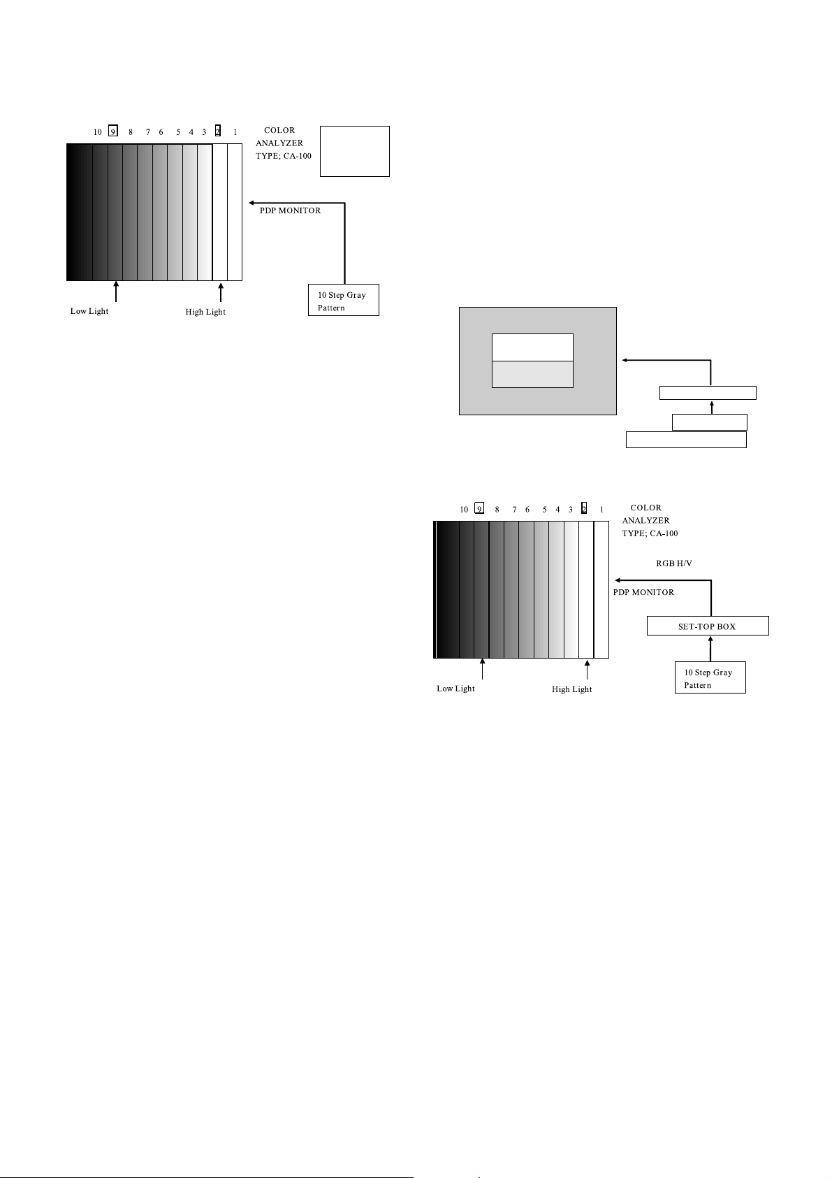
4-2. Connection Diagram of Equipment for
Measuring
ADJUSTMENT INSTRUCTIONS
VSETUP
VR806
VR805
VR804
DMM
VSC
VA
VSC CTL
V
A CTL
P814
VR803
GND
V
SETUP CTL
V
S CTL
V
S
<Fig 1> Connection Diagram of Power Adjustment for Measuring
Refer to Typical Voltage
Va
Vs
Vsc
Vsetup
75V
188V
90V
230V
Address Voltage
Sustain Voltage
Scan Voltage
Setup Voltage
COLOR
ANALYZER
TYPE; CA-100
Window Pattern
CVBS Signal Input
High Light
120±4cd/m2
Low Light
6±1cd/m2
PDP MONITOR
MSPG-2100 or
MSTG-5200
<Fig 2> Connection Diagram of Automatic Adjustment
Page 2
- 8 -
4-3. Adjustment of RGB CUT OFF
(1) Select RGB cut-off(adjustment 1) by pressing ADJ button
on Remote Control for adjustment. (If it enter to adjustment
mode, it is selected RF 13CH automatically)
(2) Press the VOL + or VOL - button.
(3) It displayed all of the black on the screen and then
adjustment is started.
(4) If adjustment is finished, exit from adjustment mode by
pressing enter button.
4-4. Adjustment of White Balance
¥ White Balance should be done after RGB cut-off become
adjustment.
¥ Operate the Zero-calibration of the CAÑ100, then stick
sensor to PDP module surface when you adjust.
(1) Select WHITE PATTERN of HEAT RUN mode by pressing
ADJ button on Remote Control for adjustment then operate
HEAT RUN more than 15 minute.
(2) Supply 10 step gray scale bar signal or window pattern in
pattern generater. (When using the STB, input RF 13CH, it
does not use, input AV.)
[ When adjustment is operated manually, perate process (3)
to (6) regular sequence, when adjustment is operated
automatically perate process (1) to (2).
(3) To adjust Low Light, stick sensor to 9th pattern(Dark),
select the R cut(adjustment 8)/B cut(adjustment 10) by
pressing ADJ button on Remote Control for adjustment
and adjust it until color coordination becomes
X=0.280±0.003, Y=0.310±0.003 and color temperature
becomes 8.800
cK ± 500cK by pressing VOL+, - button. (G-
cut fixation)
(4) To adjust High Light, stick sensor to 2th pattern(White).
Select the R Gain(adjustment 5)/G Gain(adjustment 6) by
pressing ADJ button on Remote Control for adjustment
and adjust R Gain/G Gain until color coordination becomes
X=0.280±0.003, Y=0.310±0.003 and color temperature
becomes 8.800cK ± 500cK.(B-Gain fixation)
(5) Confirm the result of the High Light adjustment.
If the deviation of High Light occur, operate the adjustment
of Low Light and High Light again.
(6) Exit adjustment mode using Enter button.
5. Color Temperature of STB
White Balance Adjustment
5-1. Required Equipment
Color Analyzer(CA-110, CA-100 or same production)
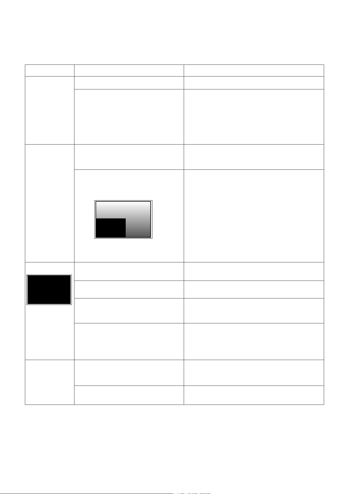
5-2. Connection diagram of equipment for
measuring
(1) To adjust the deviation of the STB signal output.
(2) Use regular PDP Monitor(JIG).
5-3. Adjustment Method
¥ Connect the STB to regular PDP Monitor.
¥ Operate the zero-calibration of the CA-100, then stick
sensor to surface of PDP module when you adjust.
(1) Select ITE PATTERN of HEAT RUN mode by pressing
ADJ button on Remote Control for adjustment, then
operate HEAT RUN more than 15 minute.
(Operate the HEAT RUN to adjust the STB at first, then if
OFF hour donÕt keep more than 3 minutes, operate next
adjustment of the STB without HEAT RUN.)
(2) Supply 10 step gray scale bar signal or window pattern in
pattern generator(RF 13CH or AV1)
[ When adjustment is operated manually, perate process (3)
to (7) regular sequence, when adjustment is operated
automatically perate process (1) to (2).
CVBS Signal Input
CVBS
Signal Input
Adjustment Adjustment
<Fig 3> Connection Diagram of Manual Adjustment
COLOR
ANALYZER
TYPE; CA-100
CVBS Signal Input
PDP MONITOR
SETTOP BOX
Window Pattern
MSPG-2100 or MSTG-5200
High Light
120±4cd/m2
Low Light
6±1cd/m2
<Fig 4> Connection Diagram of STB Automatic Adjustment
Signal Input
Adjustment Adjustment
<Fig 5> Connection Diagram of STB Manual Adjustment
Page 3

(3) Select CXA2101 ADJ STB(CH+/- button) by pressing
INSTART button on Remote Control for adjustment.
Select adjustment mode with VOL+ or VOL-.(Adjustment
0~4)
(4) To adjust Low Light, stick sensor to 9th pattern(Dark).
Select the B Cut(adjustment 0)/R Cut(adjustment 1), then
adjust the B Cut/R Cut until color coordination becomes
X=0.280±0.003, Y=0.310±0.003 and color temperature
becomes 8.800cK ± 500cK by pressing VOL+, - button.
(5) To adjust High Light, stick sensor to 2th pattern(White).
Select the R Gain(adjustment 2)/G Gain(adjustment 3),
then adjust the R Gain/G Gain until color coordination
becomes X=0.280±0.003, Y=0.310±0.003 and color
temperature becomes 8.800cK ±500cK. (B-Gain fixation)
(6) Confirm the result of the High Light adjustment.
If the deviation of High Light occur, operate the adjustment
of Low Light and High Light again.
(7) Exit adjustment mode using Enter button.
- 9 -
Page 4
- 10 -
TROUBLESHOOTING
Phenomenon
No Power
No Raster
Abnormal Picture
An example of
abnormal picture.
No Sound
PSU(Power Supply Unit) is dead.
PSU operates protect mode, when the power
lines of the boards of module or VSC(Video
Scan Converter) is short.
When the connecters of Y_board or z_board
are not inserted in a wafer or electrically
opened, the picture of monitor is very dim.
When the connecters of X_boards are not
inserted in a wafer or electrically opened,
three tenths or two tenths of picture of monitor
is not present.
In case of the connecter of
Left_Bottom_X_board is open.
PSU 12V power line is short. Or the VSC 12V
power line short.
The 41p connecter assembly(PD501), from
VSC to control board of Module, is open.
The regulators of VSC Board are wrong
condition.
In case of the clocks of Scaler(MX88L284,
IC401) or AD Converter(THS8083, IC301) are
not present.
In case of one of two connecters(P006A and
P007A) is not connected with a proper wafer,
or opened.
The regulator of VSC Board is wrong
condition.
Replace PSU.
1) Remove all connecter assemblies from PSU to X_board,
Y_board & Z_board.
2) Turn on power.
3) If PSU repeatedly operates protect mode, then replace
VSC board.
4) Otherwise, check the power lines of Module.
5) Power lines of Module are short, replace the board of
module or module.
Find the connecters, insert into a wafer or replace the
connecter.
Find the connecters, insert into a wafer or replace the
connecter.
Replace PSU. Or replace VSC board.
Check the 41p connecter assembly.
If the 41p connecter assembly is internally open, replace.
Check the regulators of VSC(IC201, 202, 205, 301, 302, 404
and 406). If these are wrong inserted or shorted to GND,
then replace.
Check clock output pin of each IC.
If output is not present,
1) Check Power line of the IC.
2) Check Crystals(X301, X401).
3) Replace IC.
Check P006A & P007A.
If it is internally open, then replace.
Check the regulator of VSC(IC601).
If these are wrong inserted or shorted to GND, then replace.
Root Cause/Responsibility Solution
Page 5
- 11 -
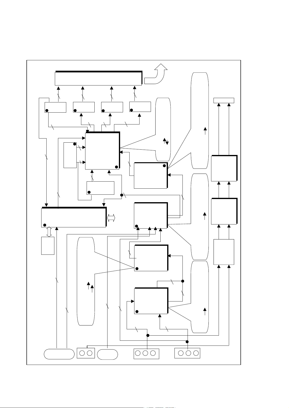
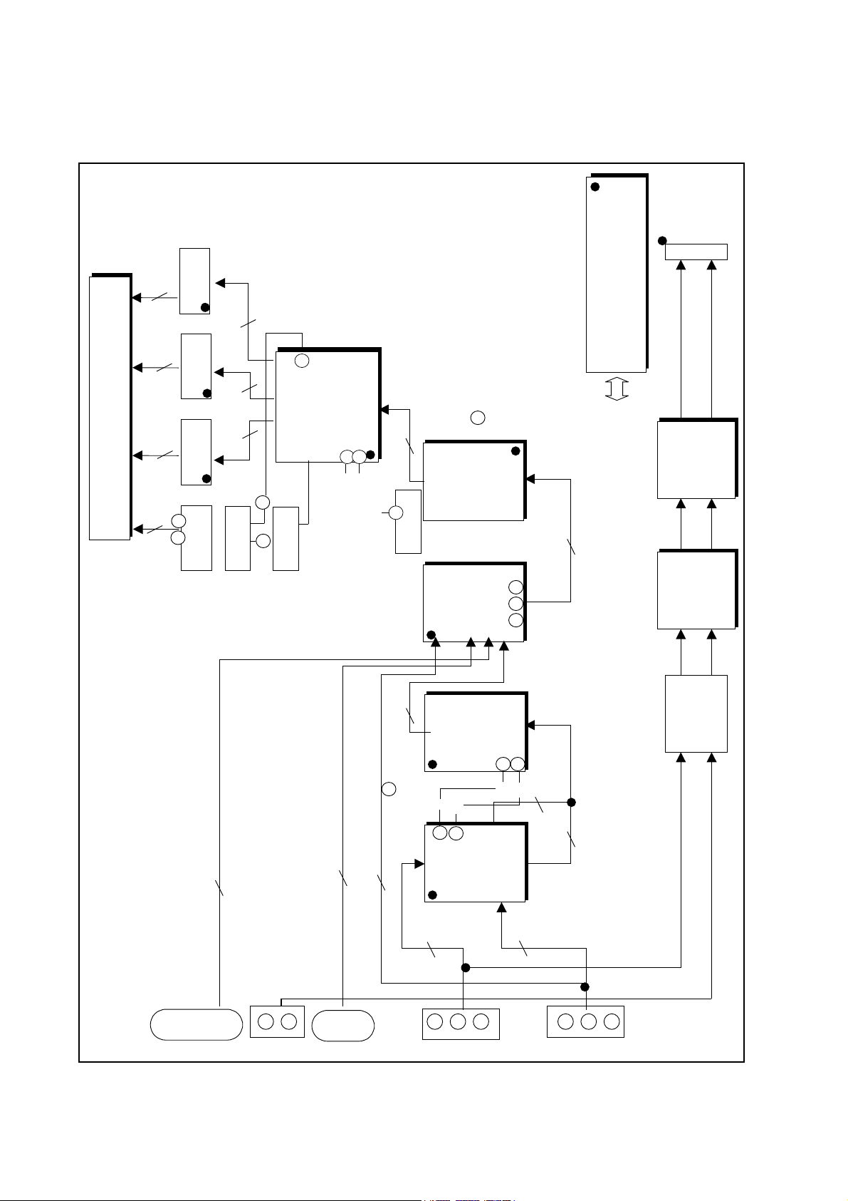
BLOCK DIAGRAM
1. VSC Board
Chip for flat panel display application
VGA SVGA scale up/down
Triple 8Bit, 80MSPS, 3.3V Video&Graphic Digitizer
with Digital PLL
Analog R/G/B 3X8 Digital R/G/B
Display Processor & Scan Rate Converter
(Format Converter)
Interlace
Progressive
15KHz 31KHz(2H X 1V)
Comb Filter Video Process
TV CVBS(Composite Video Baseband
Signal) Y/C(Y,U,V)
P101
V/R/L
P102
DVD
DS102
DS101
IC203
VPC3230
Decoder
80Pin
IC203
VPC3230
Decoder
80Pin
3
Y,Cb,Cr
CVBS
(A)
1
IC204
SDA9410
Deinterlace &
D/A
100Pin
IC204
SDA9410
Deinterlace &
D/A
100Pin
8 LU0-7
8
CHR0-7
IC303
CXA2101AQ
Video&
80Pin
IC303
CXA2101AQ
Video & Chroma
80Pin
STB-R/G/B/HS/VS(A )
5
PC-R/G/B/HS/VS(A)
5
DTV-Y/ Pb/Pr (A)
3
TV-Y/U/ V/ HVs
(A)
4
IC304
THS8083
100Pin
IC304
THS8083
100Pin
3 CXA-R/G/B(A )
IC401
MX88L284
3X2M
Scan converter
208Pin
IC401
MX88L284
3X2M
Scan converter
208Pin
IC001
M37270
EEPROM
IC001
M37280
EEPROM
Micro-Com
IC403
2M
SDRAM
IC402
2M SDRAM
(R/G/B)(D)
CAX-HS/VS
2
2
16
D0-16
A0-10
D16-31
11
16
OSD_R/G/B/YS
4
IC501
74F541
IC502
74F541
IC503
74F541
IC504
74F541
OSD_HS/VS
2
HS/VS_OUT
2
8
DOR0-7
8
DOG0-7
8
DOB0-7
STB-POWER
(A) : Analog Signal
(D) : Digital Signal
VSC DET/POWER
HDSTB_DET
STB_SCL/SDA
ANA_STB_DET
7
PVS/PHS_OUT
2
PAR0-7
8
PAG0-7
8
PAB0-7
8
PD501
(41Pin)
PDP Module
(D)
3X8
Multi-Component Processor
(Baseband Video Signal Processor)
STB, PC, DTV, TV Analog R/G/B
D-sub
25
D-sub
15
IC604
LA7222
(Audio S/W)
(A)
P601
L/R
STB/PC/DTV1
AV/DVD/DTV2
IC602
CXA2022S
(Tone Control)
IC602
CXA2022S
(Tone Control)
IC603
TDA2616
Audio Amp.
(12Wx2)
IC603
LA4282
Audio Amp.
(12Wx2)
Lout
Rout
P007A
(Spk. Jack)
I C Bus
IC002
24C08
Page 6
- 12 -
2. VSC Signal Flow(R/G/B-H/V)
P101
V/R/L
P102
DVD
DS102
DS101
IC203
VPC3230
Decoder
80Pin
IC203
VPC3230
Decoder
80Pin
3
Y,Cb,Cr
CVBS
C236
C209
C210
C211
(A)
1
IC204
SDA9410
Deinterlace
D/A
100Pin
IC204
SDA9410
Deinterlace &
D/A
100Pin
8 LU0-7
C646
C650
C645
C651
8
CHR0-7
IC303
CXA2101AQ
Video&
80Pin
IC303
CXA2101AQ
Video &Chroma
80Pin
STB-R/G/B/HS/VS( : C323~319 A)
5
PC-R/G/B/HS/VS ( : C317~319A)
5
DTV-Y/ Pb/Pr ( : C382~384
R220
A)
3
IC304
THS8083
100Pin
IC304
THS8083
100Pin
3 CXA-R (A )
IC401
MX88L284
3X2M
Scan converter
208Pin
IC401
MX88L284
3X2M
Scan converter
208Pin
Vout
(R/G/B)(D)
(D)
3X8
IC501
74F54
1
IC502
74F541
IC503
74F541
IC504
74F541
8
DOR0-7
8
DOG0-7
8
DOB0-7
PVS/PHS_OUT
2
PAR0-7
8
PAG0-7
8
PAB0-7
8
PD501
(41Pin)
D-sub
25
D-sub
15
IC604
LA7222M
(Audio S/W)
(A)
P601
L/R
STB/PC
AV/DVD/DTV
IC602
CXA2022S
(Tone Control)
IC602
CXA2022S
(Tone Control)
IC603
TDA2616
Audio Amp.
(12Wx2)
IC603
LA4282 Pin7
Pin11
C619
C610
Audio Amp.
(12Wx2)
Lout
Rout
P007A
(Spk. Jack)
IC001
M37270
EEPROM
Micro-Co
IC001
M37270
EEPROM
Micro-Com
I2C Bus
TV-Y/U/ V/ HVs
(A)
4
57
26
35 37 39
27
56
Hs:R208
Vs
Hs
Vs
H:R212
V:R213
H:R301
V:R302
Y:C305
G
B
R G B
H:R319
V:R318
R:C362
G:C366
B:C370( )
H:R345
V:R344
IC405
PLL-H:R355
6
THS-CLP
H
V
203
100
204
BA407
Vs
Hs
H
V
13
15
BA408
OSD-R/G/B/YS
Page 7
- 13 -
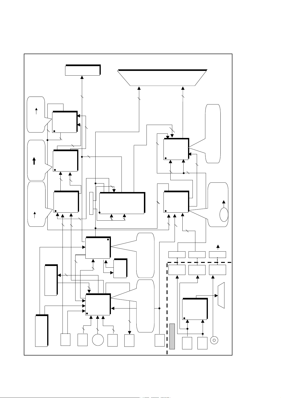
3. STB Main
Single chip multi-standard
sound processors
MONO/STEREO/Bilingual
A/V 1
SVHS
A/V 2
MNT
OUT
DTV2
in
IC 201
CXA2069Q
64pin
IC 201
CXA2069Q
64pin
3 (VRL)
2(Y/C)
3
3
MNT-L/R/V
TUNER
TUNER
IC 601
MSP3401
80pin
IC 601
MSP3401
80pin
DCF(3D)
DCF(3D)
(Digital Comb Filter)
TV Signal
(CVBS)
2
TV-L/R
2
AV-L/R
2
DCF-C/Y
1
DCF-V
IN
IC 301
VPC3230
80pin
IC 301
VPC3230
80pin
IC 701
LGTV1001
64pin
IC 701
LGTV1001
64pin
IC 302
SDA9410
100pin
IC 302
SDA9410
100pin
IC 001
M37272
u-COM
IC 001
M37272
u-COM
KEY-1
DVD
in
3
Y/U/V
IC 401
CXA2101AQ
80pin
IC 401
CXA2101AQ
80pin
IC 402
BA7657
24pin
IC 402
BA7657
24pin
P003
3
OSD R/G/B/YS
3 SCL_A, SDA_B
PC/DTV
1 S-MUTE
3
W/F-OUT(OPT)
OUT-L
OUT-R
3
K
IN
K
OUT
3
5
SDA-HS/VS/U/V/Y
3
SDA Y/V/U
2
SDA-
HS/VS
8
CHROMA0-7
8
LUMA0-7
8 C0-7
8
Y0-7
2
SCL-A
SDL-A
3
CXA R/G/B
2
CXA HS/VS
1
CXA-PC
5
R/G/B/HS/VS
P401
P402
P403
PC
R/G/B
HS/VS
DTV
R/G/B
HS/VS
PC
DTV
PC-R/L
ICX 001
BA7657F
ICX 001
BA7657F
DTV 1
IN
PC IN
PC
RGB/HV
PC/DTV-OUT
5
DTV-R/G/B
HS/VS
3
PC-R/G/B
2
PC-HS/VS
IS 501
(25Pin
Cable)
Input select switch for high
definition display
Internal broadband RGB s/w
2
Y/C
3
(
DTV 2)Y/U/V
PDP MODUL E
Interface Board
TV Audio(SIF)
(VRL)
(Y,Cb,Cr)
(R,L)
IC 602/3/4
SRS block
(option)
IC 602/3/4
SRS block
(option)
7input/3output
wideband video Amp(20MHz,-3dB)
Y/C mix circuit
A/V switch featuring I
2
C BUS
DTV2
(R,L)
(Y,Pb,Pr)
SCL-A
SDL-A
2
CXA2069Q
(pin 23/25)
R/L
PC Audio(Stereo)
DTV
RGB/HV
(R,L)
Comb filter video processor
TV Digital Y/Cr/Cb
Multi-standard color decoder
A/D converter
8bit UVin 8bit UVout
8bit Yin 8bit Yout
Image
Format converter
Interlace
Progressive
Multi-Component Processor
Analog R/G/B
R/G/B
R/G/B
Y/U/V
Page 8

- 14 -
4. STB Signal Flow(R/G/B-H/V)
IC 201
CXA2069Q
64pin
IC 201
CXA2069Q
64pin
3
MNT-L/R/V
TUNER
TUNER
IC 601
MSP3401
80pin
IC 601
MSP3401
80pin
DCF(3D)
(Digital Comb Fil ter)
DCF(3D)
(Digital Comb Fil ter)
2
TV-L/R
2
AV-L/R
IC 301
VPC3230
80pin
IC 301
VPC3230
80pin
IC 701
LGTV1001
64pin
IC 701
LGTV1001
64pin
IC 302
SDA9410
100pin
IC 302
SDA9410
100pin
IC 001
M37272
u-COM
IC 001
M37272
u-COM
KEY-1
IC 401
CXA2101AQ
80pin
IC 401
CXA2101AQ
80pin
IC 402
BA7657
24pin
IC 402
BA7657
24pin
P003
OSD R/G/B/
3 SCL_A, SDA_B
PC/DTV
1 S-MUTE
3
W/F-OUT
OUT-L
OUT-R
3
K
IN
K
OUT
3
5
SDA-Hs/Vs/V/U/Y
8
CHROMA0-7
8
LUMA0-7
8 C0-7
8
Y0-7
2
SCL-A
SDL-A
3
CXA R/G/B
P401
P402
P403
PC
R/G/B
HS/VS
DTV
R/G/B
HS/VS
PC
DTV
PC-R/L
ICX 001
BA7657F
ICX 001
BA7657F
DTV 1
IN
PC IN
PC
RGB/HV
PC/DTV-OUT
5
DTV-R/G/B
HS/VS
IS 501
(25Pin
Cable)
PDP MODULE
Interface Board
IC 602/3/4
SRS block
(option)
IC 602/3/4
SRS block
(option)
DTV2
(R,L)
SCL-A
SDL-A
2
CXA2069Q
(pin 23/25)
R/L
PC Audio(Stereo)
DTV
RGB/HV
4
5
SCL:R101
SDA:R102
4
Video:R108
C225
C-out: R228 Y-out: R225
1103
5
9
Vin:C231
Cout:R241
Yout:R237
SDA:R242
SCL:R243
72
63 58 56
71
Yin:C329
Cin:C328
1 2 3
1314
SCL:R304
SDA:R305
57
Vs:R308
23 25
27
SDA:R704
SCL:R705
Ho:R706
4
5
Ho:R321
Vo:R322
24252627
SDA:R323
SCL:R324
Vi:R321
Hi:R322
84
90
V:R417
U:R418
C407/408/409/410/411
28 29
35
37 39
R:R431
G:R432
B:R433
IC501
OPA3682
16pin
IC501
OPA3682
16pin
135
12
14
15
19
21
22
24
C460/461/462
Vs-in
Hs-in
R:L452
G:L453
B:L454
Hs-out
Vs-out
25
8
R:C501
G:C502
B:C503
1412
10
R:C513
G:C514
B:C515
Page 9

EXPLODED VIEW(MU-40PA10)
300
301
303
304
302
200
202
201
203
204
205
207
211
210
206
209
208
400
540
401
550
551
530
570
520
560
Page 10

EXPLODED VIEW PARTS LIST
200 6348Q-A001A 40” 4:3 640*480 DOU PDP
201 6871VSN168A X RIGHT TOP B/D ASSY
202 6871VSN168B X LEFT TOP B/D ASSY
203 6871VSN168C ZCNT TOP B/D ASSY
204 6871VSN168D ZSUS B/D ASSY
205 6871VSN168E ZCNT BOTTOM B/D ASSY
206 6871VSN168F X LEFT BOTTOM B/D ASSY
207 6871VSN168G X RIGHT BOTTOM B/D ASSY
208 6871VSN168H YDRV B/D ASSY
209 6871VSN168J YSUS B/D ASSY
210 6871VSN168K CTRL B/D ASSY
211 4980V00164B Vertical
300 3091V00288B CABINET ASSY
301 3210V00061B FRAME,TOP
302 3210V00062B FRAME,BOTTOM
303 3210V00063A FRAME,SIDE
304 3210B00063B FRAME,SIDE
400 3809V00212A BACK COVER ASSY
401 3301V00005A PLATE ASSY,REAR A/V
520 6871VMM602A PCB ASSY,MAIN NP-00LA MN-40PA10 VSC BOARD
530 3501V00028A BOARD ASSY,PDP POWER LINE FILTER
540 6871VSM689A PCB ASSY,CONT NP-00LA MN-40PA10 CONT
550 6871VSM690A PCB ASSY,PSW NP-00LA MN-40PA10 POWER S/W
551 5020V00445A BUTTON,POWER
560 6871VSM691A PCB ASSY,SPK NP-00LA MN-40PA10 SPK
570 3501V00027C BOARD ASSY,PDP POWER
No.
Part No.
Description
Page 11
REPLACEMENT PARTS LIST
LOCA. NO PART NO DESCRIPTION
Q107
Q108
Q109
Q110
Q111
Q112
Q201
Q202
Q301
Q302
Q303
Q305
Q306
Q307
Q601
D001
D002
D003
D004
D005
D006
D009
D010
D011
D012
D013
D014
D101
D102
D103
D104
D105
D106
D107
D108
D201
D202
D203
D301
D302
D401
D402
D601
D602
D603
D604
LD001
0TR387500AA
0TR387500AA
0TR387500AA
0TR387500AA
0TR387500AA
0TR150400BA
0TR150400BA
0TR150400BA
0TR150400BA
0TR150400BA
0TR150400BA
0TR102009AG
0TR102009AG
0TR102009AG
0TR150400BA
0DD226239AA
0DD226239AA
0DD226239AA
0DD226239AA
0DD226239AA
0DD226239AA
0DD226239AA
0DD226239AA
0DD226239AA
0DD226239AA
0DD226239AA
0DD184009AA
0DD226239AA
0DD226239AA
0DD226239AA
0DD226239AA
0DD226239AA
0DD226239AA
0DD226239AA
0DD226239AA
0DD226239AA
0DD226239AA
0DD226239AA
0DD226239AA
0DD226239AA
0DD226239AA
0DD226239AA
0DD226239AA
0DD184009AA
0DD184009AA
0DD181009AB
0DL200000CA
CHIP 2SC3875S(ALY) KEC
CHIP 2SC3875S(ALY) KEC
CHIP 2SC3875S(ALY) KEC
CHIP 2SC3875S(ALY) KEC
CHIP 2SC3875S(ALY) KEC
CHIP 2SA1504S(ASY) KEC
CHIP 2SA1504S(ASY) KEC
CHIP 2SA1504S(ASY) KEC
CHIP 2SA1504S(ASY) KEC
CHIP 2SA1504S(ASY) KEC
CHIP 2SA1504S(ASY) KEC
CHIP KRC102S SOT-23 TP KEC
CHIP KRC102S SOT-23 TP KEC
CHIP KRC102S SOT-23 TP KEC
CHIP 2SA1504S(ASY) KEC
CHIP KDS226 SOT-23
CHIP KDS226 SOT-23
CHIP KDS226 SOT-23
CHIP KDS226 SOT-23
CHIP KDS226 SOT-23
CHIP KDS226 SOT-23
CHIP KDS226 SOT-23
CHIP KDS226 SOT-23
CHIP KDS226 SOT-23
CHIP KDS226 SOT-23
CHIP KDS226 SOT-23
KDS184S CHIP 85V 300MA KEC TP
CHIP KDS226 SOT-23
CHIP KDS226 SOT-23
CHIP KDS226 SOT-23
CHIP KDS226 SOT-23
CHIP KDS226 SOT-23
CHIP KDS226 SOT-23
CHIP KDS226 SOT-23
CHIP KDS226 SOT-23
CHIP KDS226 SOT-23
CHIP KDS226 SOT-23
CHIP KDS226 SOT-23
CHIP KDS226 SOT-23
CHIP KDS226 SOT-23
CHIP KDS226 SOT-23
CHIP KDS226 SOT-23
CHIP KDS226 SOT-23
KDS184S CHIP 85V 300MA KEC TP
KDS184S CHIP 85V 300MA KEC TP
CHIP KDS181 85V 300MA KEC
LED,SAM5670(DL-2LRG) BK Y-GREEN -
LOCA. NO PART NO DESCRIPTION
IC001
IC002
IC003
IC004
IC101
IC102
IC103
IC201
IC202
IC203
IC204
IC205
IC301
IC302
IC303
IC304
IC401
IC402
IC403
IC404
IC405
IC406
IC501
IC502
IC503
IC504
IC601
IC602
IC603
IC604
IC804
IC005
IC006
Q001
Q001
Q002
Q020
Q021
Q022
Q101
Q102
Q103
Q104
Q105
Q106
0IZZVA0022B
0IAL240800A
0IFA753307A
0IFA754207A
0IPH827150A
0IFA754207A
0IFA754207A
0ISH323422A
0ISH323422A
0IIT323000D
0ISM941000A
0ISH323422A
0ISH092100B
0ISH323422A
0ISO210100B
0ITI808300B
0IMR882840B
0IEB121616A
0IEB121616A
0ISH323422A
0IPH748600D
0ISH323422A
0IPH745410A
0IPH745410A
0IPH745410A
0IPH745410A
0ISH092100B
0ISO202200A
0ISA428200A
0ISA722200A
0IKE780500Q
0TR830009BA
0TR830009BA
0TR319809AA
0TR387500AA
0TR319809AA
0TR387500AA
0TR387500AA
0TR387500AA
0TR387500AA
0TR387500AA
0TR387500AA
0TR387500AA
0TR387500AA
0TR387500AA
M37280MFSP 64PIN BK EXP
AT24C08 8D EEPROM(8K,IIC)
KA75330ZTA(KA7533ZTA) 3P,TO-92
KA75420ZTA(KA7542ZTA) 3P,TO-92
P82B715T 8SOP R/TP IIC EXTENDE
KA75420ZTA(KA7542ZTA) 3P,TO-92
KA75420ZTA(KA7542ZTA) 3P,TO-92
PQ3RF23 4P(TO-220) 3.3V REGUL
PQ3RF23 4P(TO-220) 3.3V REGUL
VPC3230D QA B4 80P QFP TRAY SO
SDA9410 100QFP BK SCAN CONVERT
PQ3RF23 4P(TO-220) 3.3V REGUL
PQ09RD21 4SIP ST REGULATOR
PQ3RF23 4P(TO-220) 3.3V REGUL
CXA2101AQ 80P,QFP BK VIDEO SIG
THS8083 100QFP BK ADC IC PD-40
MX88L284-V 208QFP BK SCALE MF0
M12L16161A-7T 50P TSOP ST 16M(
M12L16161A-7T 50P TSOP ST 16M(
PQ3RF23 4P(TO-220) 3.3V REGUL
74HC86 SOIC-14 TP QUAD 2-INPUT
PQ3RF23 4P(TO-220) 3.3V REGUL
74F541 20P SOT BK BUFFER MXIC
74F541 20P SOT BK BUFFER MXIC
74F541 20P SOT BK BUFFER MXIC
74F541 20P SOT BK BUFFER MXIC
PQ09RD21 4SIP ST REGULATOR
CXA2022S 30P SDIP ST TONE CONT
LA4282 12S 2CHX10W AUDIO AMP
LA7222 (1280 AUDIO)
KIA7805API 3P TO-220 ST REGULA
BSS83 TP PHILIPS NON N-CHANNEL
BSS83 TP PHILIPS NON N-CHANNEL
KTC3198-TP-Y (KTC1815)KEC
CHIP 2SC3875S(ALY) KEC
KTC3198-TP-Y (KTC1815)KEC
CHIP 2SC3875S(ALY) KEC
CHIP 2SC3875S(ALY) KEC
CHIP 2SC3875S(ALY) KEC
CHIP 2SC3875S(ALY) KEC
CHIP 2SC3875S(ALY) KEC
CHIP 2SC3875S(ALY) KEC
CHIP 2SC3875S(ALY) KEC
CHIP 2SC3875S(ALY) KEC
CHIP 2SC3875S(ALY) KEC
IC
TRANSISTOR
- 18 -
RUN DATE : 2001.6.8
MU-40PA10
DIODE
Page 12

- 19 -
LOCA. NO PART NO DESCRIPTION
LED001
LED002
LED003
ZD001
ZD101
ZD102
ZD103
ZD104
ZD105
ZD106
ZD201
C001
C002
C003
C008
C011
C016
C022
C026
C031
C038
C041
C050
C051
C105
C107
C109
C111
C112
C115
C118
C124
C201
C203
C206
C207
C212
C225
C229
C231
C233
C235
C238
C240
C241
C242
C243
C244
C245
C306
0DL112100AA
0DL112100AA
0DL112100AB
0DZ511109AA
0DZ511109AA
0DZ511109AA
0DZ511109AA
0DZ511109AA
0DZ511109AA
0DZ511109AA
0DZ511109AA
0CN1040K949
0CE476DD618
0CE477BF618
0CE108DF618
0CE108DF618
0CE108DF618
0CE107DD618
0CE107DD618
0CE107DD618
0CE107DD618
0CE107DD618
0CE105CK636
0CE105DK618
0CE107DD618
0CE107DD618
0CE476SF6DC
0CE476DF618
0CE476SF6DC
0CE476SF6DC
0CE476SF6DC
0CQ3331N509
0CE107DD618
0CE107DD618
0CE107DD618
0CE107DD618
0CK224DF56A
0CE107DD618
0CE476DF618
0CE107DD618
0CE107DD618
0CE476DF618
0CE107DD618
0CE107DD618
0CE107DD618
0CE107DD618
0CE107DD618
0CE107DD618
0CE107DD618
0CE476DF618
LED,SR3411(DL-11S2RN1) BK RED -
LED,SR3411(DL-11S2RN1) BK RED -
LED,SM3411(DL-11S2GN1) BK Y-GREEN
ZENER,DTZ5.1BTT11(CHIP) TP ROHM
ZENER,DTZ5.1BTT11(CHIP) TP ROHM
ZENER,DTZ5.1BTT11(CHIP) TP ROHM
ZENER,DTZ5.1BTT11(CHIP) TP ROHM
ZENER,DTZ5.1BTT11(CHIP) TP ROHM
ZENER,DTZ5.1BTT11(CHIP) TP ROHM
ZENER,DTZ5.1BTT11(CHIP) TP ROHM
ZENER,DTZ5.1BTT11(CHIP) TP ROHM
0.1M 50V Z
47UF STD 10V 20%
470UF KME 16V M
1000UF STD 16V M
1000UF STD 16V M
1000UF STD 16V M
100UF STD 10V M
100UF STD 10V M
100UF STD 10V M
100UF STD 10V M
100UF STD 10V M
1UF SHL,SD 50V M
1UF STD 50V M
100UF STD 10V M
100UF STD 10V M
47UF MVG 16V M
47UF STD 16V M
47UF MVG 16V M
47UF MVG 16V M
47UF MVG 16V M
0.033U 100V K
100UF STD 10V M
100UF STD 10V M
100UF STD 10V M
100UF STD 10V M
220000PF 2012 16V 10%
100UF STD 10V M
47UF STD 16V M
100UF STD 10V M
100UF STD 10V M
47UF STD 16V M
100UF STD 10V M
100UF STD 10V M
100UF STD 10V M
100UF STD 10V M
100UF STD 10V M
100UF STD 10V M
100UF STD 10V M
47UF STD 16V M
LOCA. NO PART NO DESCRIPTION
C318
C325
C326
C330
C338
C340
C343
C347
C349
C351
C353
C355
C357
C360
C401
C412
C414
C415
C418
C420
C424
C433
C445
C453
C457
C459
C502
C601
C602
C603
C604
C605
C606
C607
C608
C609
C610
C611
C612
C613
C614
C615
C616
C617
C618
C619
C620
C621
C622
C623
C624
C625
0CE105DK618
0CE107DF618
0CE477BF618
0CE476DF618
0CE106DF618
0CE106DF618
0CE476DF618
0CE107DD618
0CE107DD618
0CE477BF618
0CE106SF6DC
0CE106SF6DC
0CE107DD618
0CE107DD618
0CE107DD618
0CE476DF618
0CE107DD618
0CE107DD618
0CE477BF618
0CE107DD618
0CE107DD618
0CE107DD618
0CE107DD618
0CE107DD618
0CE477BF618
0CE107DD618
0CE107DD618
0CE106DF618
0CE106DF618
0CQ1042K439
0CQ4721N509
0CE475DK618
0CE475DK618
0CE475DK618
0CE475DK618
0CE475DK618
0CE106DF618
0CQ4721N509
0CE106DF618
0CQ1042K439
0CE475DK618
0CQ1042K439
0CQ2231N509
0CQ4721N509
0CQ8221N519
0CE106DF618
0CE475DK618
0CQ8221N519
0CQ1042K439
0CE476DF618
0CQ4721N509
0CQ1042K439
1UF STD 50V M
100UF STD 16V M
470UF KME 16V M
47UF STD 16V M
10UF STD 16V M
10UF STD 16V M
47UF STD 16V M
100UF STD 10V M
100UF STD 10V M
470UF KME 16V M
10UF MVG 16V 20%
10UF MVG 16V 20%
100UF STD 10V M
100UF STD 10V M
100UF STD 10V M
47UF STD 16V M
100UF STD 10V M
100UF STD 10V M
470UF KME 16V M
100UF STD 10V M
100UF STD 10V M
100UF STD 10V M
100UF STD 10V M
100UF STD 10V M
470UF KME 16V M
100UF STD 10V M
100UF STD 10V M
10UF STD 16V M
10UF STD 16V M
0.1UF S 50V J
0.0047U 100V K
4.7UF STD 50V 20%
4.7UF STD 50V 20%
4.7UF STD 50V 20%
4.7UF STD 50V 20%
4.7UF STD 50V 20%
10UF STD 16V M
0.0047U 100V K
10UF STD 16V M
0.1000UF S 50V J
4.7UF STD 50V 20%
0.1UF S 50V J
0.022U 100V K
0.0047U 100V K
0.0082U 100V K
10UF STD 16V M
4.7UF STD 50V 20%
0.0082U 100V K
0.1UF S 50V J
47UF STD 16V M
0.0047U 100V K
0.1UF S 50V J
CAPACITOR
For Capacitor & Resistors,
the charactors at 2nd and 3rd
digit in the P/No. means as
follows;
CC, CX, CK, CN : Ceramic
CQ : Polyestor
CE : Electrolytic
RD : Carbon Film
RS : Metal Oxide Film
RN : Metal Film
RF : Fusible
Page 13

- 20 -
LOCA. NO PART NO DESCRIPTION
C626
C630
C631
C635
C641
C643
C644
C645
C646
C647
C650
C651
C653
C654
C655
C656
C659
C659
C660
C660
C661
JP1
P101
P102
P601
L001
L110
L112
L113
L115
L214
DS101
DS102
R001
R002
R003
R006
R007
R225
R226
R618
R619
R655
R656
0CE107DF618
0CE108DF618
0CE106DK618
0CE476DF618
0CE106DK618
0CE477DK618
0CE477DK618
0CE106DF618
0CE106DF618
0CE476DF618
0CE106DF618
0CE106DF618
0CE477DK618
0CE477DK618
0CE477DK618
0CE477DK618
0CE107DH618
181-120K
0CE107DH618
181-120K
0CE107DH618
6612VLH002A
380-389N
380-389P
6612VJH018A
0LA0102K119
0LC18000A02
0LC18000A02
0LC18000A02
6140VB0006A
0LA0102K119
6630VGA002B
6630VGA001C
0RD3302F609
0RD1002F609
0RD3001F609
0RD4700F609
0RD5100F609
0RN5602F409
0RN2202F409
0RD0331H609
0RD0331H609
0RD4700H609
0RD4700H609
100UF STD 16V M
1000UF STD 16V M
10UF STD 50V M
47UF STD 16V M
10UF STD 50V M
470UF STD 50V 20%
470UF STD 50V 20%
10UF STD 16V M
10UF STD 16V M
47UF STD 16V M
10UF STD 16V M
10UF STD 16V M
470UF STD 50V 20%
470UF STD 50V 20%
470UF STD 50V 20%
470UF STD 50V 20%
100UF STD 25V M
2200PF 4KV M
100UF STD 25V M
2200PF 4KV M
100UF STD 25V M
JACK,RCA SP026B 4P RD/BK/BK/R
JACK,RCA S-456S-N A/V 3P RD-W
JACK,RCA S-456S-P A/V 3P GR-B
JACK,RCA PJ6058C-A A/V 2P MON
INDUCTOR,10UH K
INDUCTOR,CHIP CERATECH R/TP
INDUCTOR,CHIP CERATECH R/TP
INDUCTOR,CHIP CERATECH R/TP
COIL,CHOKE 12UH 0.3PHY,PHY 15.5TURN SB804
INDUCTOR,10UH K
CONNECTOR (CIRC),D-SUB 25PIN
CONNECTOR (CIRC),D-SUB 15PIN 2.29MM
33K OHM 1/6 W 5.00%
10K OHM 1/6 W 5.00%
3K OHM 1/6 W 5.00%
470 OHM 1/6 W 5.00%
510 OHM 1/6 W 5.00%
56K OHM 1/6 W 1.00%
22K OHM 1/6 W 1.00%
3.3 OHM 1/2 W 5.00%
3.3 OHM 1/2 W 5.00%
470 OHM 1/2 W 5.00%
470 OHM 1/2 W 5.00%
LOCA. NO PART NO DESCRIPTION
SW001
SW002
SW003
SW004
BA301
BA302
BA303
BA304
BA305
BA306
BA407
BA408
BA409
BA410
BA411
BA412
BA413
BA414
BA415
BA416
BA417
BA418
BA419
BA420
BA421
BA422
BA423
BA424
F601
F602
L001
L002
L104
L105
L106
L107
L108
L201
L202
L203
L204
L205
L206
L207
L208
L209
L210
6600VM2006A
140-315A
140-315A
140-315A
140-315A
6210VC0004A
6210VC0004A
6210VC0004A
6210VC0004A
6210VC0004A
6210VC0004A
6210VC0004A
6210VC0004A
6210VC0004A
6210VC0004A
6210VC0004A
6210VC0004A
6210VC0004A
6210VC0004A
6210VC0004A
6210VC0004A
6210VC0004A
6210VC0004A
6210VC0004A
6210VC0004A
6210VC0004A
6210VC0004A
6210VC0004A
6210VC0004A
6200VJS001A
6200VJS001A
6210VC0006A
6210VC0006A
6210VC0006A
6210VC0005A
6210VC0005A
6210VC0005A
6210VC0006A
6210VC0006A
6210VC0006A
6210VC0005A
6210VC0005A
6210VC0005A
6210VC0006A
6210VC0006A
6210VC0006A
6210VC0006A
6210VC0006A
SWITCH,PUSH SDDF3PATP011
SWITCH,TACT SKHV17910B NON 12V
SWITCH,TACT SKHV17910B NON 12V
SWITCH,TACT SKHV17910B NON 12V
SWITCH,TACT SKHV17910B NON 12V
FILTER(CIRC),EMC BK3216 4S600
FILTER(CIRC),EMC BK3216 4S600
FILTER(CIRC),EMC BK3216 4S600
FILTER(CIRC),EMC BK3216 4S600
FILTER(CIRC),EMC BK3216 4S600
FILTER(CIRC),EMC BK3216 4S600
FILTER(CIRC),EMC BK3216 4S600
FILTER(CIRC),EMC BK3216 4S600
FILTER(CIRC),EMC BK3216 4S600
FILTER(CIRC),EMC BK3216 4S600
FILTER(CIRC),EMC BK3216 4S600
FILTER(CIRC),EMC BK3216 4S600
FILTER(CIRC),EMC BK3216 4S600
FILTER(CIRC),EMC BK3216 4S600
FILTER(CIRC),EMC BK3216 4S600
FILTER(CIRC),EMC BK3216 4S600
FILTER(CIRC),EMC BK3216 4S600
FILTER(CIRC),EMC BK3216 4S600
FILTER(CIRC),EMC BK3216 4S600
FILTER(CIRC),EMC BK3216 4S600
FILTER(CIRC),EMC BK3216 4S600
FILTER(CIRC),EMC BK3216 4S600
FILTER(CIRC),EMC BK3216 4S600
FILTER(CIRC),EMC BK3216 4S600
FILTER(CIRC),EMI ZJY51R5-4P TDK DC 50VOLT 2A
FILTER(CIRC),EMI ZJY51R5-4P TDK DC 50VOLT 2A
FILTER(CIRC),EMC FBMH3216 HM501NT
FILTER(CIRC),EMC FBMH3216 HM501NT
FILTER(CIRC),EMC FBMH3216 HM501NT
FILTER(CIRC),EMC BK2125 HS 750
FILTER(CIRC),EMC BK2125 HS 750
FILTER(CIRC),EMC BK2125 HS 750
FILTER(CIRC),EMC FBMH3216 HM501NT
FILTER(CIRC),EMC FBMH3216 HM501NT
FILTER(CIRC),EMC FBMH3216 HM501NT
FILTER(CIRC),EMC BK2125 HS 750
FILTER(CIRC),EMC BK2125 HS 750
FILTER(CIRC),EMC BK2125 HS 750
FILTER(CIRC),EMC FBMH3216 HM501NT
FILTER(CIRC),EMC FBMH3216 HM501NT
FILTER(CIRC),EMC FBMH3216 HM501NT
FILTER(CIRC),EMC FBMH3216 HM501NT
FILTER(CIRC),EMC FBMH3216 HM501NT
JACK
COIL
CONNECTOR
RESISTOR
SWITCH
FILTER
For Capacitor & Resistors,
the charactors at 2nd and 3rd
digit in the P/No. means as
follows;
CC, CX, CK, CN : Ceramic
CQ : Polyestor
CE : Electrolytic
RD : Carbon Film
RS : Metal Oxide Film
RN : Metal Film
RF : Fusible
Page 14

- 21 -
LOCA. NO PART NO DESCRIPTION
L211
L213
L301
L302
L303
L304
L305
L306
L401
L402
L403
L404
L405
L407
L408
L409
L501
L502
L601
L602
L603
PA001
X001
X201
X301
X401
A1
A2
A3
6210VC0005A
6210VC0005A
6210VC0006A
6210VC0006A
6210VC0006A
6210VC0006A
6210VC0006A
6210VC0006A
6210VC0006A
6210VC0006A
6210VC0006A
6210VC0005A
6210VC0006A
6210VC0006A
6210VC0006A
6210VC0006A
6210VC0006A
6210VC0005A
6210VC0006A
150-F09A
6210VC0006A
3890V01035A
3920V00255A
6726VH0001A
156-A01P
6202VDB007B
6202VDT002B
6202VDT002B
3828VA0254E
6710V00042G
6866VA9001B
FILTER(CIRC),EMC BK2125 HS 750
FILTER(CIRC),EMC BK2125 HS 750
FILTER(CIRC),EMC FBMH3216 HM501NT
FILTER(CIRC),EMC FBMH3216 HM501NT
FILTER(CIRC),EMC FBMH3216 HM501NT
FILTER(CIRC),EMC FBMH3216 HM501NT
FILTER(CIRC),EMC FBMH3216 HM501NT
FILTER(CIRC),EMC FBMH3216 HM501NT
FILTER(CIRC),EMC FBMH3216 HM501NT
FILTER(CIRC),EMC FBMH3216 HM501NT
FILTER(CIRC),EMC FBMH3216 HM501NT
FILTER(CIRC),EMC BK2125 HS 750
FILTER(CIRC),EMC FBMH3216 HM501NT
FILTER(CIRC),EMC FBMH3216 HM501NT
FILTER(CIRC),EMC FBMH3216 HM501NT
FILTER(CIRC),EMC FBMH3216 HM501NT
FILTER(CIRC),EMC FBMH3216 HM501NT
FILTER(CIRC),EMC BK2125 HS 750
FILTER(CIRC),EMC FBMH3216 HM501NT
FILTER(CIRC),EMC SQE2222 7-14MH 0.37PHY 48TURN
FILTER(CIRC),EMC FBMH3216 HM501NT TAIYOYUDEN 3
BOX,MU-40PA10.AAMZMZ 40Ó
PACKING,MN-40PA10(PD-40X3) TOP/BOT 1KG
REMOTE CONTROLLER RECEIVER,TSOP1238RF1 38KHZ
RESONATOR,CRYSTAL HC49U 8.000MHZ
30
RESONATOR,CRYSTAL HC49U 20.250MHZ 3
RESONATOR,CRYSTAL SX-1SMD 14.318MHZ
RESONATOR,CRYSTAL SX-1SMD 14.318MHZ
MANUAL,OWNERS NP00LE MU-40PA10 ZENITH
REMOTE CONTROLLER,MONITOR ONLY
SIGNAL CABLE,2990-9C UL 1161 AWG 26 TWI 700
LOCA. NO PART NO DESCRIPTION
MISCELLANEOUS
ACCESSORIES
For Capacitor & Resistors,
the charactors at 2nd and 3rd
digit in the P/No. means as
follows;
CC, CX, CK, CN : Ceramic
CQ : Polyestor
CE : Electrolytic
RD : Carbon Film
RS : Metal Oxide Film
RN : Metal Film
RF : Fusible
Page 15
Page 16
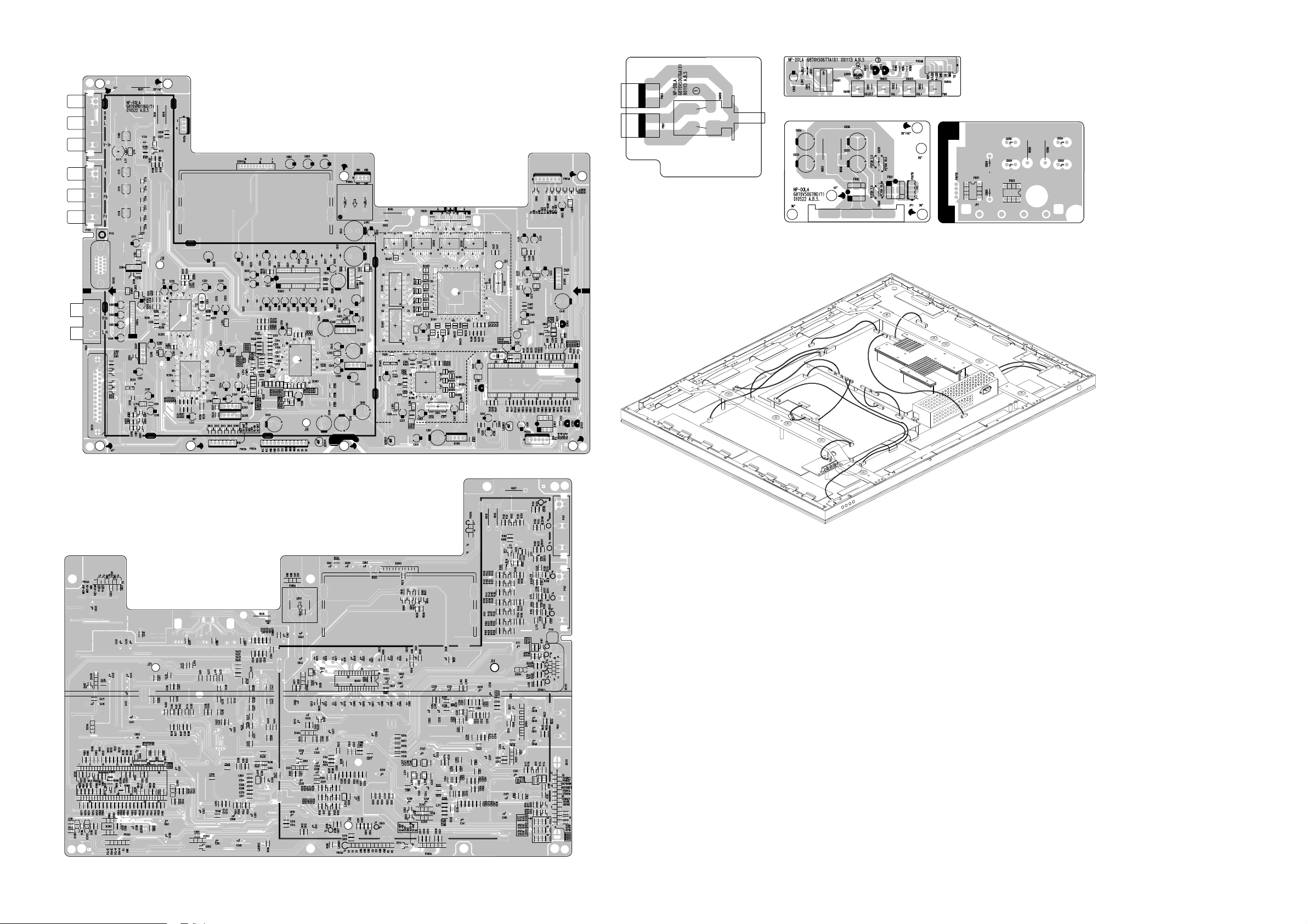
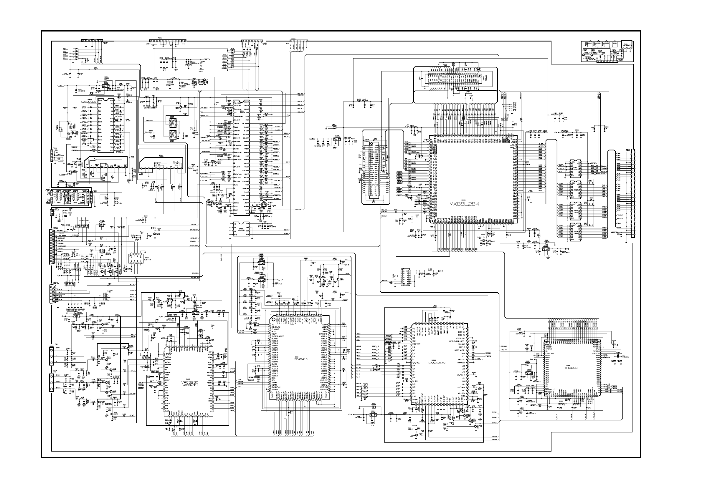
PRINTED CIRCUIT BOARD
MAIN(TOP)
MAIN(BOTTOM)
WIRING DIAGRAM
POWER S/W CONTROL
SPK(TOP) SPK(BOTTOM)
P15
P004B
P004A
P14
PD501
P100
P802
P803
P802
P801
P006A
P810
P811
P806
P801
P809
P815
P005A
P003A
P304
P007B
P007A
P302
P301
P303
P807
P805
P804
P102
 Loading...