

Page 1
Aclvanced Video
Imaging
THE QUALITY GOES IN BEFORE THE NAME GOES ON®
iAviso para nuestros
clientes de habla hispana:
consulte la informacibn que
aparece al final de este manual!
Direct-View Color TV
MTS Stereo Audio
Picture-In-Picture
Surround Sound
recycled paper
50 percent
Return the Product Registru/ion
Card, and your "IFV could be free!
Page 2
WARNING:
IO REDUCE THE RISK OF ELECTRIC SHOCK DO NOI
REMOVE COVER (OR BACK). NO USER SERVICEABLE
PARTS INSIDE. REFER TO QUALIFIED SERVICE
PERSONNEL.
TO PREVENT FIRE OR SHOCK HAZARDS, DO NOT EXPOSE
THIS PRODUCT TO RAIN OR MOISTURE.
The lightning flash with arrowhead symbol, within an equilateral
triangle, is intended to alert the user to the presence of uninsulated
"dangerous voltage" within the product's enclosure that may be of
sufficient magnitude to constitute a risk of electric shock to persons.
The exclamation point within an equilateral triangle is intended to
alert the user to the presence of important operating and maintenance
(servicing) instructions in the literature accompanying the appliance.
Safety Tips
Refer to the "Safety Tips" booklet that came with your
product for important safety considerations.
Note to Cable TV System Installer
This reminder is provided to call the cable TV system
installer's attention to Article 820-40 of the NEC that
provides guidelines for proper grounding and, in particular,
specifies that the cable ground shall be connected to the
grounding system of the building, as close to the point of
the cable entry as practical.
Power-Cord Polarization
This product is equipped with a polarized alternating-
current line plug (a plug having one blade wider than the
other.) This plug will fit into the power outlet only one
way. This is a safety feature. If you are unable to insert the
plug fully into the outlet, try reversing the plug. lfthe plug
should still fail to fit, contact your electrician to replace
your obsolete outlet. Do not defeat the safety purpose of
the polarized plug.
CAUTION
To prevent electric shock, match wide blade of plug to
wide slot, fully insert.
ATTENTION
Pour _viter les chocs _lectriques, introduire la lame la plus
large de la fiche dans la home correspondante de la prise et
pousser jusqu'au fond.
Clot)._ight _ i_CllitJlElectronics Uorpotauon 19_)4 a,_ _J<<
Page 3
CONTENTS
IN IRODUCI ION
Welcome ................................. ii
Installation Considerations ..................... ii
CONNECTIONS FOR YOUR TV
Connection Center on Back of TV ............... 1-1
Other A/V Jacks on TV ...................... 1-1
Step 1. Make Basic Connection to TV ............. 1-2
Step 2. Make VCR Connections to TV ............ 1-3
Step 3. Make Super-VHS VCR Connections to TV .... 1-4
Step 4. Make A/V Connections to Auxiliary
A/V Jacks (VIDEO 3 IN or S-VIDEO 2 IN) ....... 1-4
Step 5. Make Connections to Monitor Out Jacks ...... 1-4
Step 6. Make Surround Sound Connections to TV ..... 1-5
Step 7. Make External Speaker Connections to TV ..... 1-5
Step 8. Make Audio Connection to Stereo Amplifier .... 1-6
THE FIRST TIME YOU OPERATE YOUR TV
Step 1. Connect the Power .................... 2-1
Step 2. Select Your Viewing Source .............. 2-1
Step 3. Use Auto Program .................... 2-1
Step 4. Time Functions ...................... 2-1
Step 5. Use Other Options .................... 2-2
REMOTE CONTROL MODEL SC2400
Operation ............................... 3-1
Installing Batteries .......................... 3-1
REMOTE CONTROL MODEL MBR3430
Operation ............................... 4-1
Choose the Operating Mode ................... 4-1
TV Operations ............................ 4-2
VCR Operations ........................... 4-3
Cable-TV Operations ........................ 4-4
Preparation for Use ......................... 4-5
Installing Batteries .......................... 4-5
Auto Find Mode ........................... 4-5
Programming Brand Codes .................... 4-6
TV, VCR and Cable-TV Operating Codes .......... 4-7
QUICK REFERENCE TO ON-SCREEN MENUS
Available Menus ........................... 5-1
Summary of Menu Items ..................... 5-1
Menu Operation Example ..................... 5-3
SOURCE MENU
Source Selection ........................... 6-1
Source Identification ........................ 6-1
SETUP MENU
Auto Program ............................. /- 1
Ch. Add/Del .............................. 7-1
Ch. Labels ............................... 7-2
Tuning Band .............................. 7-3
Auto Tuning .............................. 7-3
Source ID ............................... 7-3
Clock Set ................................ 7-4
Captions ................................ 7-4
AUDIO MENU
Bass ................................... 8-1
Treble .................................. 8-1
Balance ................................. 8-1
Audio .................................. 8-1
SEQ ................................... 8-1
Surround ................................ 8-1
VIDEO MENU
Contrast ................................. 9-1
Brightness ............................... 9-1
Color .................................. 9-1
Tint ................................... 9-1
Sharpness ................................ 9-1
Color Temp .............................. 9-1
Video Filter .............................. 9-1
Auto Flesh ............................... 9-1
Picture Pref .............................. 9-1
PIP MENU
Ch. Guide .............................. 10-1
Ch. Review ............................. 10-2
PIP Source .............................. 10-2
PIP Size ............................... 10-3
PIP Color .............................. 10-3
PIP Tint ................................ 10-3
PIP OPERATION AND CONNECTIONS
PIP Overview ............................ 11-1
Typical Connections ........................ 11-1
How to Select Main Picture & PIP Source ......... 11-3
PIP Functions ............................ 11-4
MAINTENANCE AND TROUBLESHOOTING
Caring for Your TV ........................ 12-1
Extended Absence ......................... 12-1
TV Picture Interference ..................... 12-1
Before Calling for Service .................... 12-2
Product Registration Card
Recommended Accessories For Your Television
Aviso para nuestros clientes de habla hispana
Your Zenith Warranty
HOW TO USE YOUR OPERATING GUIDE
THIS OPERATING GUIDE DESCRIBES A FAMILY OF TV MODELS. SOME MODELS HAVE FEATURES THAT
ARE NOT PROVIDED ON OTHER MODELS, SUCH AS AUXILIARY JACKS. DIFFERENT CONTROL PANELS AND
REMOTE CONTROLS MAY BE USED FROM MODEL-TO-MODEL. REFER TO THE APPLICABLE SECTIONS OF
THIS OPERATING GUIDE FOR THE FEATURES AND ITEMS PROVIDED WITH YOUR TV.
2736-0 i
Page 4
INTRODUCTION
WELC OM E
Welcome into the lmnily of Zenith Color Television owners.
This guide provides instructions on how to operate your
new TV. It is supplemented by a booklet containing Safety
Tips. We urge you to read these publications carefully so
that you will receive full enjoyment from your new Zenith
TV for many years to come.
Your new TV has been designed and built to give you the
very best in quality, features and performance. There are
many regional Zenith distributors and thousands of distribu-
tor-approved Zenith service centers throughout the U.S.,
Canada and Mexico who can attend promptly and effec-
tively to ordinary service needs.
If you should have an unusual performance or service problem
that cannot be satisfactorily resolved by your distributor-
approved Zenith service center, contact the regional Zenith
distributor in your area, or write:
Zenith Electronics Corporation
Customer Service Department
1900 N. Austin Avenue
Chicago, Illinois 60639-5079
Telephone: (312) 745-5152
Mon-Fri, 8:00 a.m. - 4:30 p.m. Central Time
Send the model number, serial number, and datc of pro-
chase or original installation, with a full explanation of the
problem and the service history. We will welcome the op-
portunity to look into your specific question or problem and
to be of assistance in resolving it promptly.
The model and serial numbers of your new TV are located on
the back of the TV cabinet. For your future convenience and
protection, we suggest that you record these numbers here:
ModelNo.
Serial No.
INSTALLATION CONSIDERATIONS
Before you install your TV...
Ventilation -- Proper ventilation keeps your TV
running cool. Air circulates through perfora-
tions in the back and bottom of the cabinet. Do
not block these vents or you will shorten the life
of your TV.
Power Source -- Your TV isdesigned to operate
on normal household current, 120volt 60 Hertz
AC. Do not attempt to operate it on DC current.
Power Cord -- Your power cord has a polar-
ized plug as required by Underwriters' Labora-
tories. It has one regular blade and one wide
blade and fits only one way into a standard elec-
trical outlet. If the blades will not enter either
way, your outlet is very old and non-
standard. A new outlet should be installed by a
qualified electrician.
Safe Operation -- Your TV is manufactured
and tested with your safety in mind. However,
unusual stress caused by dropping or mishan-
dling, exposure to flood, fire, rain or moisture,
or accidental spilling of liquids into the TV, can
result in potential electrical shock or fire haz-
ards. lfthis happens, have your TV checked by
a service technician before using it again.
Please read and observe each safety point in the "Safety
Tips" folder when installing and using your TV.
FIXED PATTERN DISPLAY CAUTION -- If you use your
TV for video games, teletext or other fixed displays, avoid
setting the BRIGHTNESS control for an excessively bright
picture. A bright, fixed pattern, if used for long periods of
time, can result in a permanent imprint on the TV picture
tube. You can reduce this possibility by alternating the use
of the fixed pattern display with normal TV picture viewing,
by turning down the CONTRAST control for sustained
fixed pattern use, and byturning offthe fixed pattern dis-
playwhen not in use.
Page 5
CONNECTIONS FOR YOUR TV
CONNECTION CENTER ON BACK OF TV
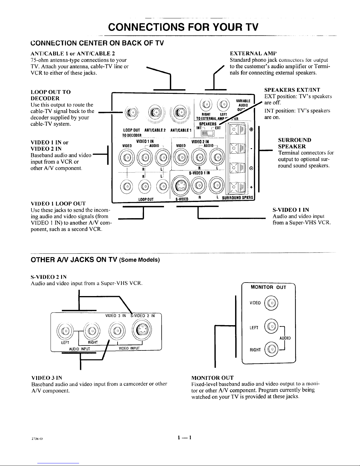
ANT/CABLE 1 or ANT/CABLE 2
75-ohm antenna-type connections to your
TV. Attach your antenna, cable-TV line or
VCR to either of these jacks.
LOOP OUT TO
DECODER
Use this output to route the
cable-TV signal back to the
decoder supplied by your
cable-TV system.
VIDEO 1 IN or
VIDEO 2 IN [
Baseband audio and video
input from a VCR or
other A/V component.
VIDEO 1 LOOP OUT i
Use these jacks to send the incom-
ing audio and video signals (from
VIDEO I IN) to another A/V com-
ponent, such as a second VCR.
I !
EXTERNAL AMP
Standard phono jack COl]llCCtOfStOl output
to the customer's audio amplifier or Termi-
nals for connecting external speakers.
SPEAKERS EXT/INT
EXT position: TV's speakers
are off.
INT position: TV's speakers
are on.
SURROUND
SPEAKER
Terminal connectors lbr
output to optional sur-
round sound speakers.
S-VIDEO 1 IN
Audio and video input
from a Super-VHS VCR.
OTHER A/V JACKS ON TV (Some Models)
S-VIDEO 2 IN
Audio and video input from a Super-VHS VCR.
I
\
VIDEO 3 IN '_-VIDEO 2 IN
AUDIO INPUT VIDEO INPUT
MONITOR OUT
VIDEO
AUDIO
VIDEO 3 IN
Baseband audio and video input from a camcorder or other
A/V component.
MONITOR OUT
Fixed-level baseband audio and video output to a moni-
tor or other A/V component. Program currently being
watched on your TV is provided at these jacks.
273_,-o 1 -- 1
Page 6

CONNECTIONS FOR YOUR TV
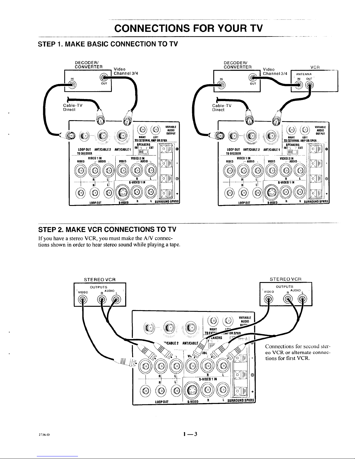
STEP 1. MAKE BASIC CONNECTION TO TV
Select the hook up that best fits your needs. See the following
diagrams.
NOTE: The antenna may be connected to the ANT/CABLE 2
jack, however, connecting to the ANT/CABLE 1jack may
produce a better picture in weak signal areas.
Antenna
Flat Wire
300 oh m ',
i
OR
, i
Round Wire
75 ohm
300/75 ohm
Adaptor
LOOPOUT ANT/CABLE2 ANT/CABLE1
TODECODER
_ VARIABLE
AUDIO
OUTPUT
RIGHT LEFT
TO EJTERHAL AMPOR SPUR
SPEAKERS -----
lOT 7 I EXT "r_" LLLLI
\©/ 5
VIDEO 1 IN VIDEO 2 IN
VIDEO r AUDIO : I VIDEO r-AUDIO • _ .
R L ............. "
c4._- q P- s.v,0Eo,,,
/ R LI ! .,_ _-_
LOOPOUT I S-VIDEO O L SURROUNDSPKRS
Antenna
VCH
Video
_,han nel 3/4
VARIABLE
AUDIO
TO EXTERNALAMP OR SPKR
..... ] :: ] SPEAKERS _----=
INT 7 _ EXT "0" IIIJ
LOOPOUT ANT/CABLE2 ANT/CABLE1 _ _
TODEDODER =
VIDEO 1 IN VEEOi N
LOOPOUT I S-VIDE--O R L SURROUNDSPKRS,
Cable_ IV
(Direct Connection
toTV) _1
lilT I ; I (_
TLoOoOE;oODUETRANT/CABLE2 ANT/CABLE1 _
,IOEO VIOE01AI_DBO : [VIDEO VIO'rO 2Ai_'o , _-,q-r
LOOPOUT O-VIBEO
Cable-TV
(Direct Connection
Through VCR to TV)
VCR
i IN ANTLNNA
Video
nnel 3/4
(continued on next page)
_7_B-o I --2
Page 7
CONNECTIONS FOR YOUR TV
STEP 1. MAKE BASIC CONNECTION TO TV
DECODER/
CONVERTER
Video
I IChannel 314
- VARIABLE
_;',,A,A;,_&,.o=
: I SPEAKERS
I,.T• ,E3. VlIIII •
LOOPOUT ANT/CABLE2 ANTICABLE1L/ _
_ToDECODER
VIDEO1IN VIDEO2 IN
VIOEO r AUDIO _ VIDEO r-AUDiO 1
/ _ u _--_- ,°dl!ll e
LOOPOUT l-_EO R t SURROUNOSPKRS,
DECODER/
CONVERTER VCR
Video
I ,N (_ I Channel 3/41 A..Eo.A
; IN OUT i
zv. j__
................. SPEAKERS
INT I r EXT \n/_ll_
TOOECOoEoLOOPOUTANT/CABLE2 ANT/CABLE1 _](_
VIDEO1IN
VIDEO r AUDIO
LOOPOUT
VIDEO2IN
vmo ! AUDIO,.. "WllL_,I
e L 0 IIIIqI®
@®®
O-VIDEO R L SURROUNDSPKRS
STEP 2. MAKE VCR CONNECTIONS TO TV
If you havea stereoVCR, you mustmake theA/V connec-
tions shown in orderto hearstereosoundwhile playinga tape.
2736-0 ! --3
Page 8
CONNECTIONS FOR YOUR TV
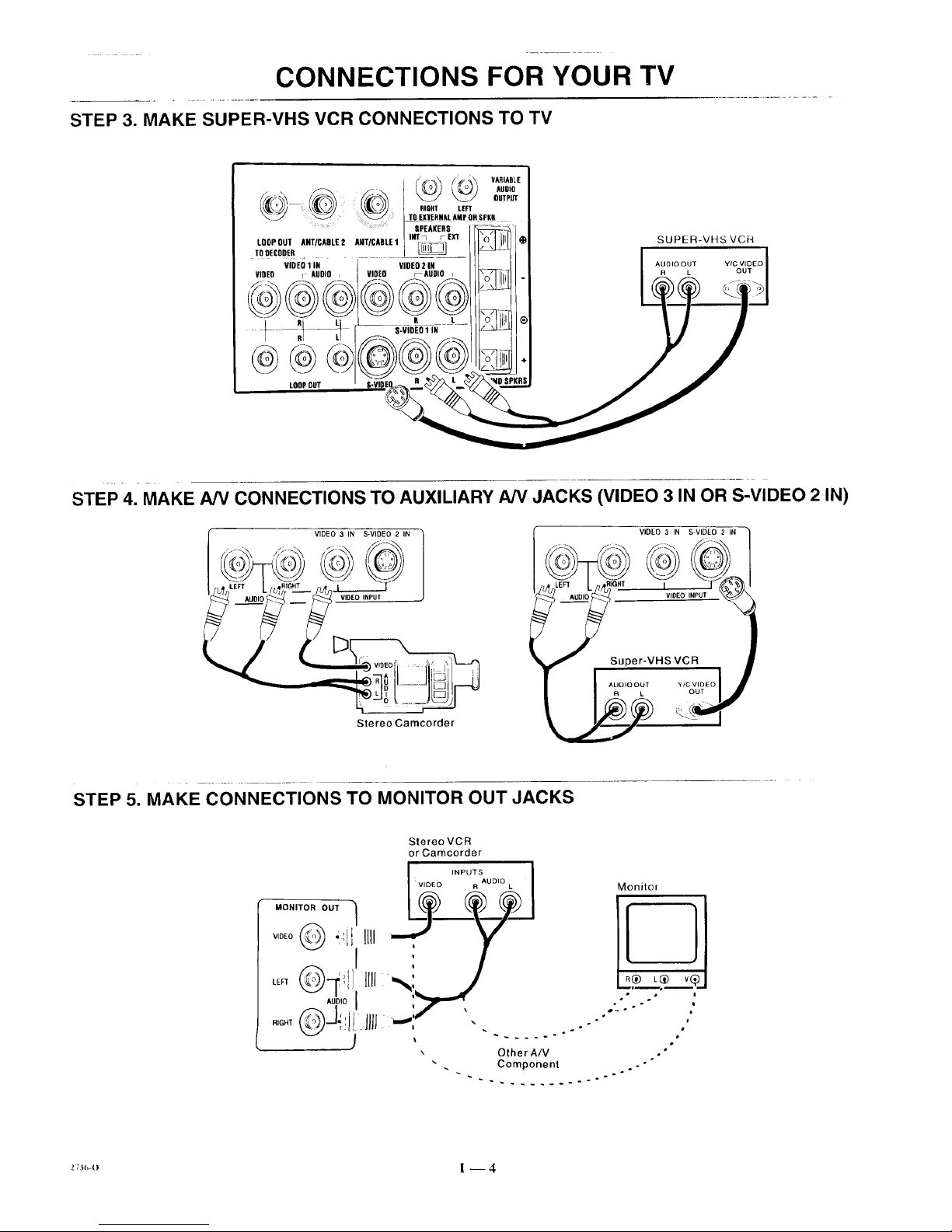
STEP 3. MAKE SUPER-VHS VCR CONNECTIONS TO TV
@@@
LOOPRUT
_ VARIABLE
_ 0_TP_
RIGHT LEFT
= TO EXTERNAL AMPOR SPKR
SPEAKERS
INTq FEXI"
LOOPOUT ANT/CABLE 2 AHT/CABLE1
TO DECOOER
VIREO 1 IN VIDEO 2 IN
VIDEO r AUDIO _ VIDEO FAUDIO
O L
S-VIDEO 1 IN
SUPER-VHS VCR
AUDIOOUT
R L
STEP 4. MAKE A/V CONNECTIONS TO AUXILIARY A/V JACKS (VIDEO 3 IN OR S-VIDEO 2 IN)
i v,oE?3,Ns+,_E+o2,. _._
Stereo Cameorder
VIDEO 3 IN S-VIDEO 2 IN
-- IVtOEO t
Super-VHS VCR
/
.......+ ++o_.?oolj
STEP 5. MAKE CONNECTIONS TO MONITOR OUT JACKS
Stereo VCR
or Camcorder
INPUTS _
R AUDIO
MONITOR OUT
v0+_ -_ilI'lm :
LE. X,_0!]Iml_ '
RIGHT _J"_il_ Jill ...-''
", Other AIV
Monitor
I
• oo i
o
. Component . ."
_ .-
Page 9
CONNECTIONS FOR YOUR TV
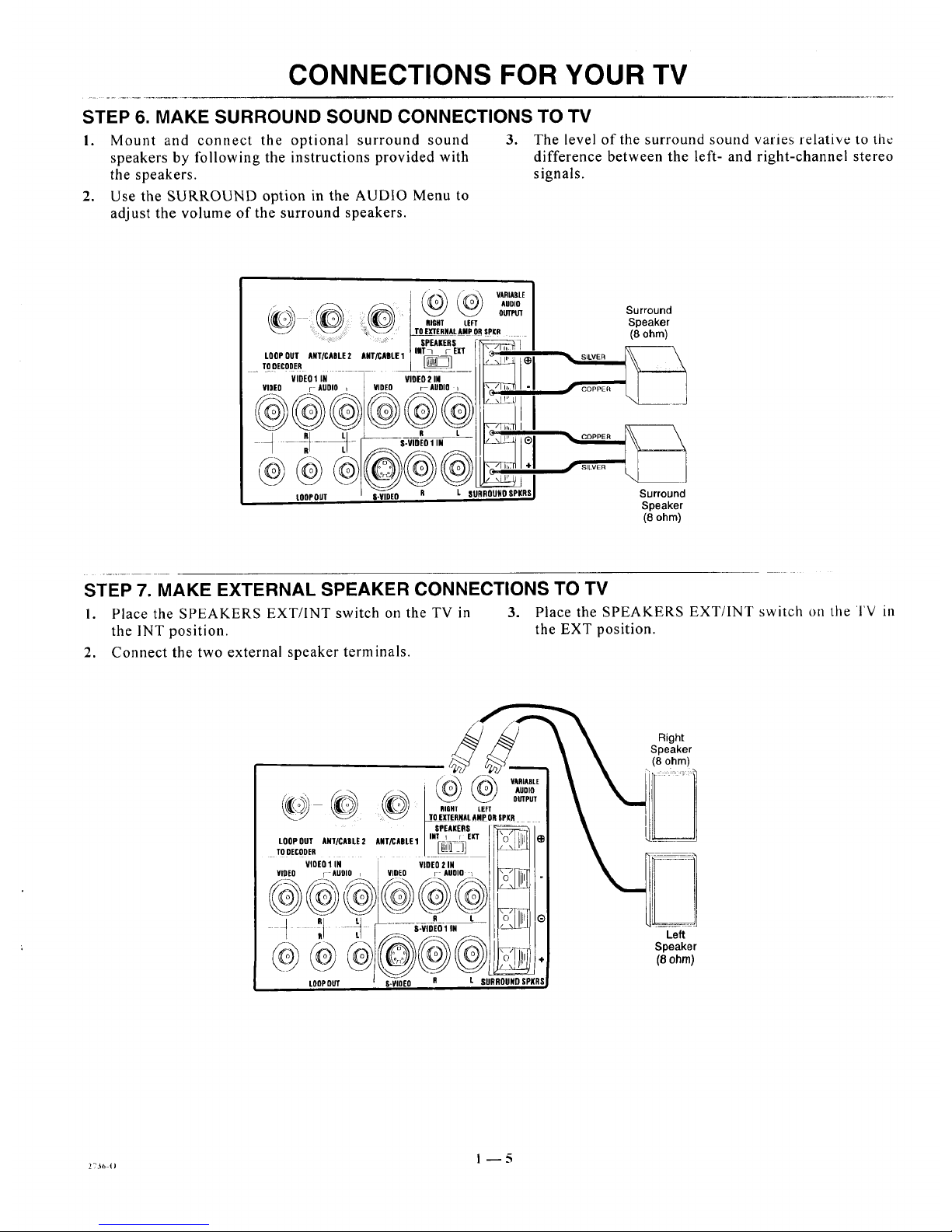
STEP 6. MAKE SURROUND SOUND CONNECTIONS TO TV
1. Mount and connect the optional surround sound 3. The level of the surround sound varies relative tothc
speakers by following the instructions provided with difference between the left- and right-channel stereo
the speakers, signals.
2. Use the SURROUND option in the AUDIO Menu to
adjust the volume of the surround speakers.
' _ VARIABLE
...... ] SPEAKERS f ,_,_,_,_,_,_,_,_,_,_._,_
,t}t},,t},_, _ /V_l_l'"""
VIDEO r AUDIO i VIDEO r AUDIO i llr,_/li.n -
LOOPt}gT $-VIDEt} R L SURROUHO SPKRSJ
Surround
Speaker
(8 ohm)
Surround
Speaker
(8 ohm)
STEP 7. MAKE EXTERNAL SPEAKER CONNECTIONS TO TV
I. Place the SPEAKERS EXT/lNTswitch on theTVin 3. Place the SPEAKERS EXT/INTswitch on the I'V in
the INT position, the EXT position.
2. Connect the two external speaker terminals.
Right
Speaker
(8 ohm)
Left
Speaker
(8 ohm)
Page 10
CONNECTIONS FOR YOUR TV
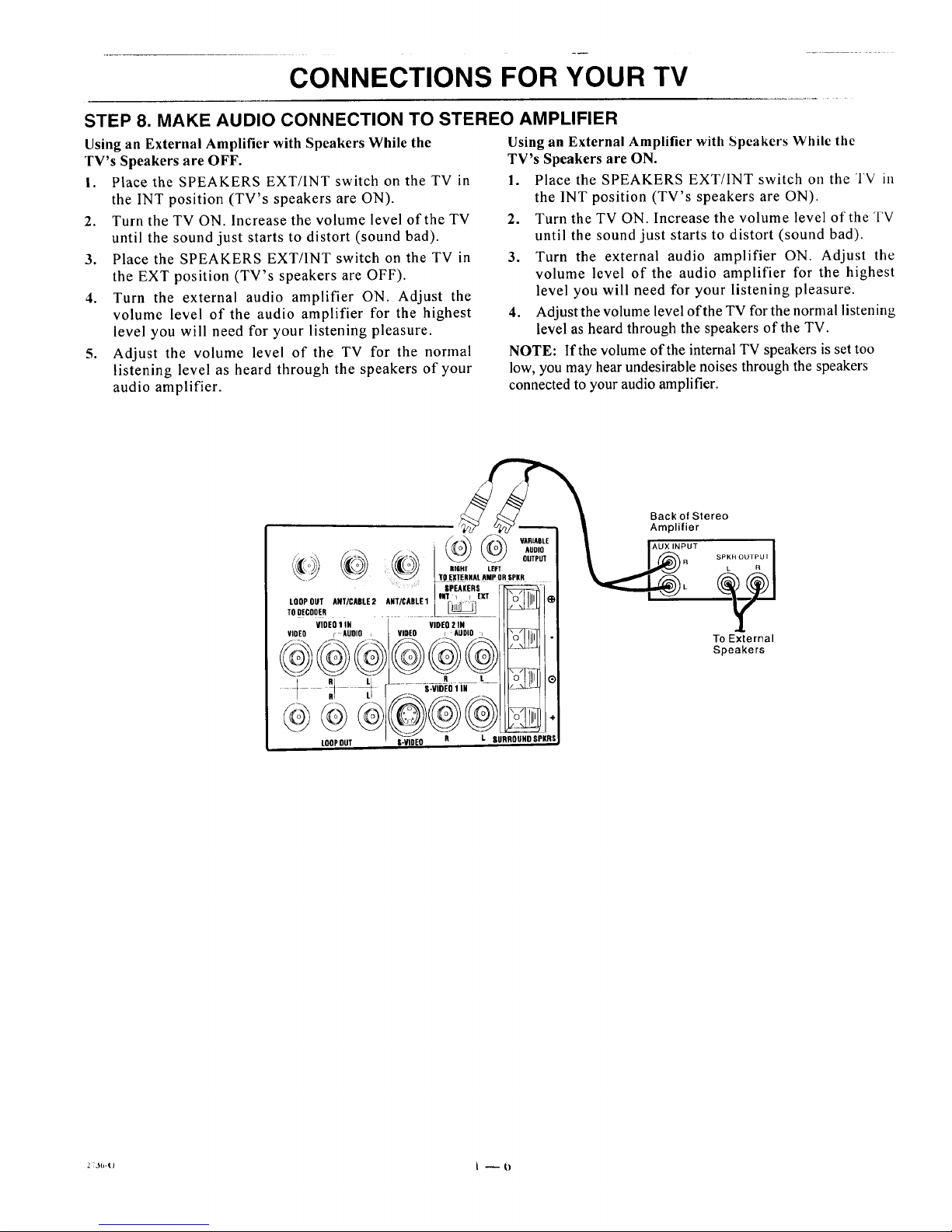
STEP 8. MAKE AUDIO CONNECTION TO STEREO AMPLIFIER
Using an External Amplifier with Speakers While the
TV's Speakers are OFF.
I. Place the SPEAKERS EXT/INT switch on the TV in
the INT position (TV's speakers are ON).
2. Turn the TV ON. Increase the volume level of the TV
until the sound just starts to distort (sound bad).
3. Place the SPEAKERS EXT/INT switch on the TV in
the EXT position (TV's speakers are OFF).
4. Turn the external audio amplifier ON. Adjust the
volume level of the audio amplifier for the highest
level you will need for your listening pleasure.
5. Adjust the volume level of the TV for the normal
listening level as heard through the speakers of your
audio amplifier.
Using an External Amplifier with Spcakers While the
TV's Speakers are ON.
1. Place the SPEAKERS EXT/INT switch on the TV ill
the INT position (TV's speakers are ON).
2. Turn the TV ON. Increase the volume level of the TV
until the sound just starts to distort (sound bad).
3. Turn the external audio amplifier ON. Adjust the
volume level of the audio amplifier for the highest
level you will need for your listening pleasure.
4. Adjust the volume level of the TV for the normal listening
level as heard through the speakers of'the TV.
NOTE: If the volume of the internal TV speakers is set too
low, you may hear undesirable noises through the speakers
connected to your audio amplifier.
@ VARIABLE
-°'°
_ OUTPUT
RIGHT LEFT
TOE_XTERNALAMP OR SPKR
....: SPEAKERS
lilT I [ EXT W]]i!ll
LDOPOLIT ANT/CABLE2 ANT/CABLE1
TO DECODER
VIOEO1IN
VIDEO F AUOIO
t
@@@)
LOOPOUT
VIDEO 2 IN
VIDEO _ AUDIO i
R t
@@@s
S-ViDEO R L SURRDUND SPKRS
Back of Stereo
Amplifier
)R _SPKH OUTPU [
To External
Speakers
2;J(,-() t -- {)
Page 11
THE FIRST TIME YOU OPERATE YOUR TV
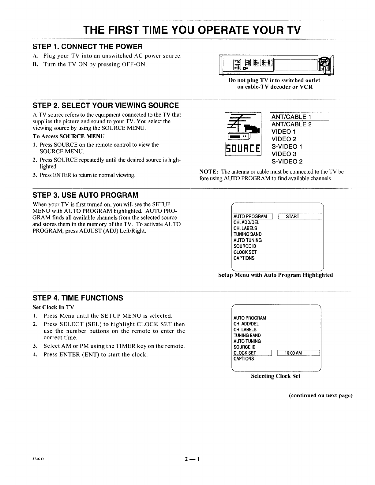
STEP 1. CONNECT THE POWER
A. Plug your TV into an unswitched AC power source.
B. Turn the TV ON by pressing OFF-ON.
Do not plug TV into switched outlet
on cable-TV decoder or VCR
STEP 2. SELECT YOUR VIEWING SOURCE
A TV source refers to the equipment connected to the TV that
supplies the picture and sound to your TV. You select the
viewing source by using the SOURCE MENU.
To Access SOURCE MENU
1. Press SOURCE on the remote control to view the
SOURCE MENU.
2. Press SOURCE repeatedly until the desired source is high-
lighted.
3. Press ENTERto return to normalviewing.
[ANT/CABLE 1 ]
ANT/CABLE 2
VIDEO 1
VIDEO 2
50UFII"E s-V,DEOi
VIDEO 3
S-VIDEO 2
NOTE: The antenna or cable must be connected to the TV be-
fore using AUTO PROGRAM to find available channels
STEP 3. USE AUTO PROGRAM
When your TV is first turned on, you will see the SETUP
MENU with AUTO PROGRAM highlighted. AUTO PRO-
GRAM finds all available channels from the selected source
and stores them in the memory of the TV. To activate AUTO
PROGRAM, press ADJUST (ADJ) Left/Right.
AUTOPROGRAM
CH.ADD/DEL
CH.LABELS
TUNINGBAND
AUTOTUNING
SOURCEID
CLOCKSET
CAPTIONS
Setup Menu with Auto Program Highlighted
STEP 4. TIME FUNCTIONS
Set Clock in TV
I. Press Menu until the SETUP MENU is selected.
2. Press SELECT (SEL) to highlight CLOCK SET then
use the number buttons on the remote to enter the
correct time.
3. Select AM or PM using the TIMER key on the remote.
4. Press ENTER (ENT) to start the clock.
AUTO PROGRAM
CH.ADD/DEL
CH.LABELS
TUNINGBAND
AUTOTUNING
SOURCEID
CLOCKSET
CAPTIONS
11 10:00AM ___
Selecting Clock Set
(continued on next page)
2736-0 2-- 1
Page 12
THE FIRST TIME YOU OPERATE YOUR TV
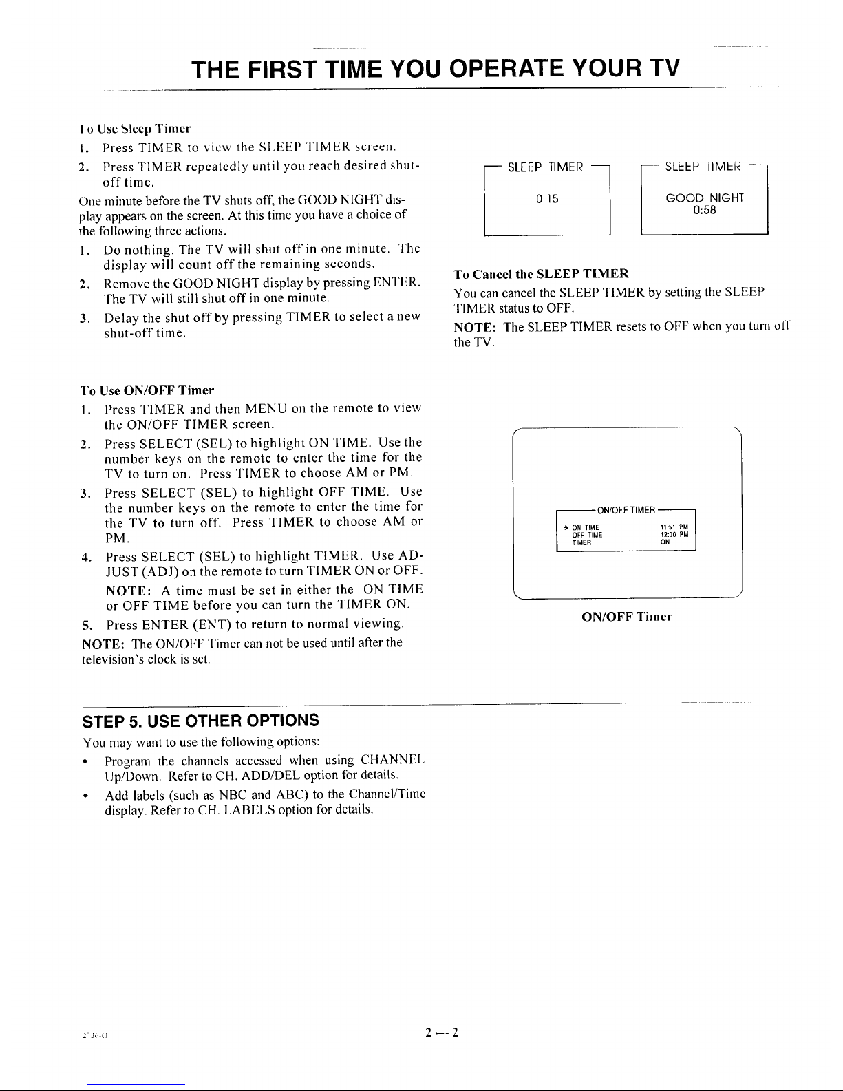
i o Use Sleep Timer
i. Press TIMER to view the SLEEP TIMER screen.
2. Press TIMER repeatedly until you reach desired shut-
off time.
One minute before the TV shuts off, the GOOD NIGHT dis-
play appears on the screen. At this time you have a choice of
the following three actions.
I. Do nothing. The TV will shut off in one minute. The
display will count off the remaining seconds.
2. Remove the GOOD NIGHT display by pressing ENTER.
The TV will still shut off in one minute.
3. Delay the shut off by pressing TIMER to select a new
shut-off time.
-SLEEP TIMER -_
I 0:15
SLEEP ilMER -
GOOD NIGHT
0:58
To Cancel the SLEEP TIMER
You can cancel the SLEEP TIMER by setting the SLEEP
TIMER status to OFF.
NOTE: The SLEEP TIMER resets to OFF when you turn off
the TV.
1"oUse ON/OFF Timer
I. Press TIMER and then MENU on the remote to view
the ON/OFF TIMER screen.
2. Press SELECT (SEL) to highlight ON TIME. Use the
number keys on the remote to enter the time for the
TV to turn on. Press TIMER to choose AM or PM.
3. Press SELECT (SEL) to highlight OFF TIME. Use
the number keys on the remote to enter the time for
the TV to turn off. Press TIMER to choose AM or
PM.
4. Press SELECT(SEL) to highlight TIMER. Use AD-
JUST (ADJ) on the remote to turn TIMER ON or OFF.
NOTE: A time must be set in either the ON TIME
or OFF TIME before you can turn the TIMER ON.
5. Press ENTER (ENT) to return to normal viewing.
NOTE: The ON/OFF Timer can not be used until after the
television's clock is set.
-- ONIOFF TIMER
I
-_ ON TliqlE 11:51 P_t4I
OFF TIME 12:00 PM ]
TIMER ON ]
ON/OFF Timer
STEP 5. USE OTHER OPTIONS
You may want to use tile following options:
• Program the channels accessed when using CHANNEL
Up/Down. Refer to CH. ADD/DEL option for details.
• Add labels (such as NBC and ABC) to the Channel/Time
display. Refer to CH. LABELS option for details.
z J_,. 2 .... 2
Page 13
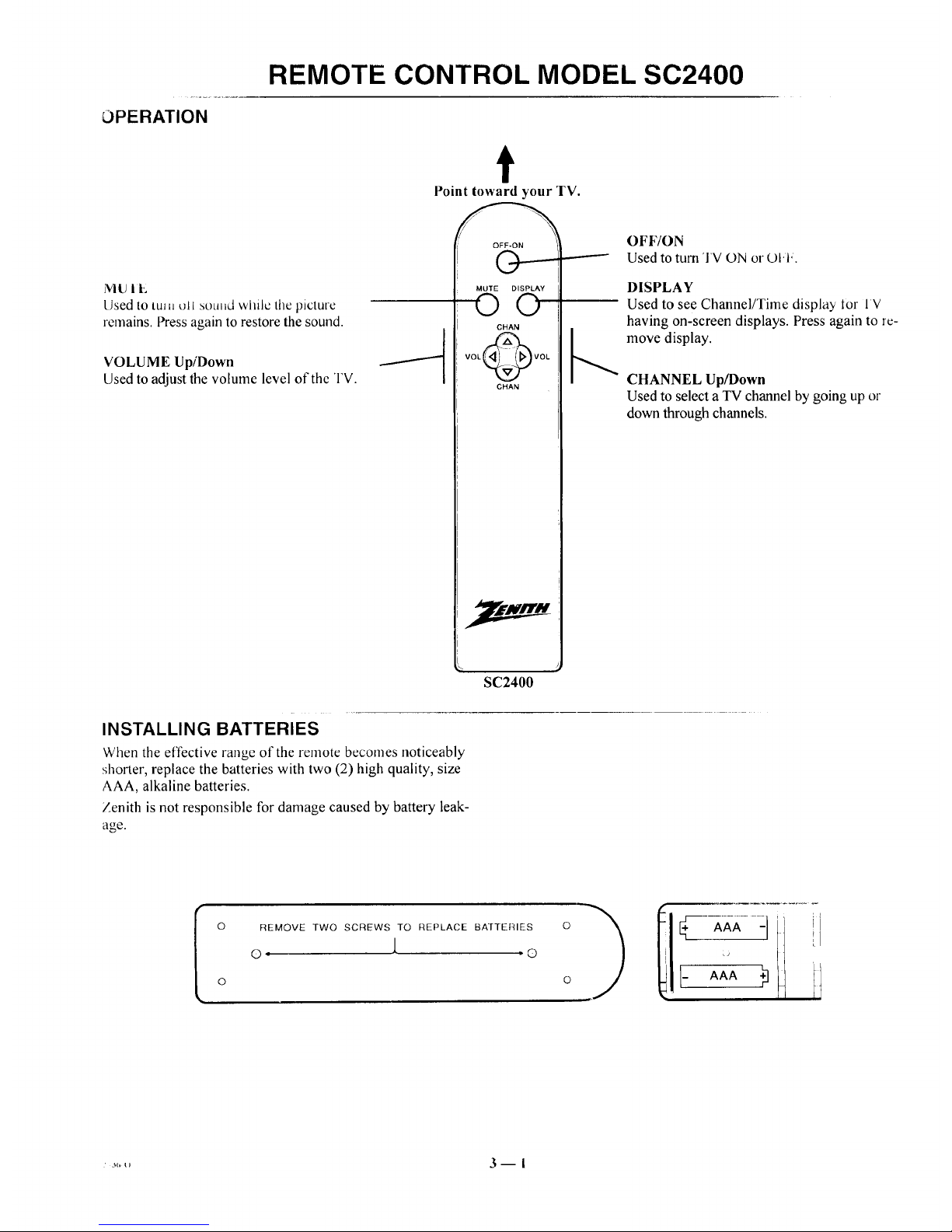
OPERATION
REMOTE CONTROL MODEL SC2400
t
Point toward your TV.
MU lit,;
Used to tin, oli sound while the picture
remains. Press again to restore the sound.
VOLUME UpiDown
Used to adjust the volume level of the TV.
INSTALLING BATTERIES
When the effective range of the remote becomes noticeably
shorter, replace the batteries with two (2) high quality, size
AAA, alkaline batteries.
Zenith is not responsible for damage caused by battery leak-
age.
OFF-ON
MUTE DISPLAY
©O
CHAN
VOL_VOL
CHAN
SC2400
OFF/ON
Used to turn 'I'V ON or O1.1.
DISPLAY
Used to see Channel/Time display Ior IV
having on-screen displays. Press again to rc-
_., move display.
CHANNEL Up/Down
Used to select a TV channel by going up or
down through channels.
I
o
REMOVE TWO SCREWS TO REPLACE BAJTERIES
o J. ®
o I- AAA.)
il
1.,,,,, 3 m i
Page 14

REMOTE CONTROL MODEL MBR3430
OPERATION
The multi-brand remote supplied with your new Zenith TV al-
lows you to operate most models of infrared (IR) remote-
controlled TVs, VCRs and cable-TV converters, even if they
are all different brands.
Your multi-brand remote has already been programmed to ol_-
erate your Zenith TV, a Zenith VCR and a Zenith cable-TV de-
coder. It must be "taught" to operate other brands. Refer to
"Auto Find Mode" and "Programming Your Remote Con-
trol" for details.
CHOOSE THE OPERATING MODE
To operate your TV, VCR, CABLE-TV decoder, or an AUX
(auxiliary) device, you must first choose the remote's mode of
_peration. To select the mode, press the MODE key until the
]esired indicator lights.
Some KEYS on the remote will always operate a particular ap-
pliance. For example, VOLUME always operates the TV vol-
ume and PLAY always operates the VCR. The function of
other keys depends on the mode selected.
Point toward unit
to be controlled
Operating mode selection
and indicators
Menu operations on TV
and some VCRs
Numbered buttons for
channel selection and other
uses
Learn functions for user
programmed sequences
NOTE: See following pages
for operating instructions.
r-w-q r-vd_
AO'G AO'lil
QUIT
®®®
®®®
® CE"TER)
(Z_D CZ) C_
SWAP TIMER
s;EI--
SEQ
1=:1 I:::i:) I:3D 1::2:1
RECORD STOP PAUSE SEARCH
REW PLAY F FWD TVNCR
] .
MBR3430
Controlled device
OFF/ON
Special features on IV and
some VCRs
Channel Up/Down
for TVs, VCRs and cable
Volume Up/Down for TV
Special features on some
TVs and some VCRs
273_-o 4 -- I
Page 15

REMOTE CONTROL MODEL MBR3430
'I'V OPERATIONS
The following functions and operations apply to your Zenith
TV. The remote control must be in the TV mode to operate
your TV.
MODE
Used to select the TV mode of
operation.
TV
Lights when TV mode of
operation is selected.
CC (Closed Captions)
Used to view closed captions
broadcast with some television
programs.
MENU, SELECT and ADJUST
Used with on-screen menus to
see menu, select an option, and
adjust that option.
Numbered Buttons
Used to select a TV channel.
ENTER
Used to view the Channel!Time
Display or to remove any on-
screen menu or display.
LEARN
Used to program remote.
PIP
Used to activate Picture-In-Pic-
ture inset.
SWAP
Used to swap picture in PIP inset
with the main television picture.
t
Point toward your 'FV.
®®@
®®®
®® ®
PIP
STOP PAUSE
REW PLAY F FWD TV/VC
OFF/ON
Used to turn 1 V ON oi t)t,l..
SOURCE
Used to display the menu of'l V
sources for some TVs. Press again
step through the source selec-
tions. On some TVs, press to select
AUX (Auxiliary) channel.
FLASHBK (Flashback)
Used to return to the last TV
channel you were watching.
CHANNEL Up/Down
Used to sequence throughthe TV
channels.
VOLUME Up/Down
Used to adjust the TV's volume.
MUTE
Used to turn offsound while the
picture remains. Press again to re-
store the sound.
SPATIAL EQUALIZATION
(SEq)
Used to select SEQ audio mode on
TVs equipped with SEQ feature.
FREEZE
Used to freeze the motion of the pic-
ture on the PIP inset.
TIMER
Used to activate the SLEEP
TIMER. Press repeatedly to select
desired turn-off time.
z'l_-,, 4 n 2
Page 16

REMOTE CONTROL MODEL MBR3430
VCR OPERATIONS
The following functions and operations apply to Zenith VCR
models built after 1988. The remote control must be in the
VCR mode to operate your VCR.
The remote control supplied with your VCR ma._nave kcys
not duplicated on the new remote. If these functions are de-
sired, the original remote control will have to be used.
MODE
Used to select the VCR mode of
operation.
VCR
Lights when VCR mode of
operation is selected.
MENU, SELECT, ADJUST
and QUIT
Used with on-screen menus and pro-
gramming options of the VCR. See
VCR operating guide for details.
Numbered Buttons
Used to select a TV channel through
the VCR. Also, used to set the
timer in the VCR, and to enter pro-
gramming information.
ENTER
Used with the numbered buttons to se-
lect a TV channel throughthe VCR.
AM/PM
Used to set timer during program-
ruing.
t
Point toward your VCR.
® ®®
® ®®
® ®®
LEARN
SOURCE
FLASHBR
CHANNEL
8)
VOLUME
C=:) C=)..
PIP
SWAP TIMER SEQ
RECORD STOP PAUSE SEARCH
REW PLAY F FWD TV/VCR
OFF/ON
j Used to turn VCR O1"40l ul, l,.
FLASHBK (Flashback)
Used during VCR playback to
J iew the channel tuned by the
VCR.
CHANNEL Up/Down
Used to sequence through channels
on the VCR.
TIMER
Activates TIME RECORD on
J some VCRs. See the VCR operat-
ing guide for details.
TV/VCR
Used to select the source of the p_v-
grams seen on the TV. Switches
the VCR between TV mode and
VCR mode.
TV Mode: Channels are selected
through the TV.
VCR Mode: Channels or tape op-
eration are selected through the
VCR.
RECORD, STOP, PAUSE,
SEARCH, REW, PLAY and
F FWD
Used for tape recording and play-
back functions. See the VCR operat-
ing guide for details.
273_,-o 4 -- 3
Page 17

REMOTE CONTROL MODEL MBR3430
CABLE-TV OPERATIONS
Ihe following functions and operations apply to a Zenith cable- The remote control supplied with your cable-l V decodci m,L_
I"Vdecoder. The remote control must be in the CABLE mode to have keys not duplicated on the new remote. If these functions
operate your cable-TV decoder, are desired, the original remote control will have to be used.
MODE
Used to select the Cable mode of
operation.
CABLE
Lights when CABLE mode of
operation is selected.
MENU, SELECT, ADJUST
and QUIT
Functions depend on Cable-TV sys-
tem. See Cable-TV decoder operat-
ing guide for details.
Numbered Buttons
Used to select channels through
Cable-TV decoder.
t
Point toward your Cable-TV decoder.
ENTER
Used with the nunabered buttons to se-
lect a TV channel through the
Cable-TV decoder.
®®®
®®®
®®®
LEARN PIP FREEZE
OFF-ON
V
SOURCE
0
FLASHBK
IAI
CHANNEL
IVl
I,AI
MUTE
I
SWAP TIMER SEQ
RECORD STOP PAUSE SEARCH
REW PLAY F FWD TVIVCR
OFF/ON
j Used to turn VCR ON o_ ut-t,.
SOURCE
Selects "A" or "B" cable cham_uJs.
CHANNEL Up/Down
Used to sequence through chmmcts
on the Cable-TV decoder.
z73(,-(, 4 -- 4
Page 18

REMOTE CONTROL MODEL MBR3430
PREPARATION FOR USE
Batteries are provided with this remote, but you must install
them before using the remote.
INSTALLING BATTERIES
When the effective operating range of your remote becomes
,loticeably shorter, replace the batteries with two high-quality,
alkaline, size AAA batteries.
Zenith is not responsible for damage caused by battery leak-
age.
After installing new batteries, the remote control will set itsell
to Zenith brand codes, as follows: TV=101, VCR=201 and
CABLE=301.
If you are going to operate equipment that uses different
codes, the remote must be reprogrammed for those codes.
AUTO FIND MODE
Use Auto Find to automatically find the brand code needed to
operate your equipment.
NOTE: If no button is pressed for 60 seconds or more during
Auto Find, the remote will automatically exit Auto Find with-
out storing any brand codes. (LEDs will flash 3 times upon ex-
iting.)
1. Turn on the equipment you wish the remote to oper-
ate.
2. Press and hold LEARN until mode indicator lights
(about 4 seconds).
3. Use MODE to select the mode you wish to program
(TV, VCR or CABLE).
4. Enter "00" then press ENTER within 2 seconds. All four
mode indicator lights will turn ON and then OFF, leaving
the mode indicator light for the active mode ON.
5. Point remote towards the equipment.
6. Press and release OFF/ON on the remote about once every
second, until the equipment turns OFF. Press ENTER
before pressing any other buttons.
If you press OFF/ON again before pressing ENTER
Auto Find will have to be repeated.
7. Try other buttons to see if they operate the equipment.
if they do not, you may wish to reenter Auto Find and
try to find another code. The remote will begin with
codes starting from where it left off prior to exiting
Auto Find.
iOI lljLj
CABLE-TV DECODER
8. Repeat Auto Find for each piece of equipment you _m_t
your remote to operate. NOTE: Only one brand code can
be programmed in each of the four modes.
If no brand code has been entered after searching through all
brand codes in any mode, the remote will flash all four mode
indicator lights in a chasing manner. Wait 60 seconds or press
ENTER or LEARN to return to normal operation.
2736-0 4_ 5
Page 19

REMOTE CONTROL MODEL MBR3430
PROGRAMMING BRAND CODES
Introduction
Before using your new remote control, it must be programmed
to recognize the brands of equipment it will be used to oper-
ate. If you are using a Zenith VHS VCR or a Zenith cable-TV
decoder, the remote has already been programmed for you.
Find the code that corresponds to each brand and type of
equipment you are going to operate. Refer to Tables 1, 2 and 3.
For example, if you were programming the remote for use
with a Zenith TV, you would look for "Zenith" in "Table 1",
and find code "101."
Write the brand codes for your equipment on the following
lines.
TV CODE:
CABLE CODE:
VCR CODE:
I. Press MODE repeatedly to select tile desired 'IV,
VCR or CABLE operating mode for the remote.
2. Press LEARN for about 5 seconds until the MODE
indicator lights for the selected TV, VCR or CABLE
mode of operation.
3. Enter the proper brand code number for the equipment
to be controlled.
4. Press LEARN. All three mode indicators should light
briefly, then turn off to indicate the brand code has
been programmed.
5. If all three mode indicators fail to light briefly, an
error has occurred. Repeat Steps 1-4 to try again.
6. Repeat steps 1-4 to program the remote for the other
equipment you are using.
NOTE: CABLE mode can be programmed to operate a sec-
ond TV or second VCR, if desired.
When batteries are removed: It will be necessary to reprogram
the proper VCR and cable-TV decoder codes.
Operating Mode
Indicators
Numbered Buttons
Use to enter code number
for desired brand.
LEARN Button
ADJ _ ADJ
@®@
®®®
®@@
® (EN+E.)
SOURCE
0
FLASHBK
,,(Z:) (:Z3) (:ZZ)
LEARN PIP FREEZE
CHANNEL
VOLUME
MUTE
I
SWAP IIMER SEO
_ QD (:::g_ (:Z:)
RECORD STOP PAUSE SEARCH
Gi_ (3ED (IE_
REW PLAY F FWD TVNCR
Operating MODE Selector
2736-0 416
Page 20

REMOTE CONTROL MODEL MBR3430
TV, VCR AND CABLE-TV OPERATING CODES
Table 1. TV Codes by Brand
IV Brand TV Brand
Name Code Name Code
Admiral 116 Montgomery Ward 119
Admiral 121 Montgomery Ward 121
Akai 104 Montgomery Ward 130
Amark 103 NEC 104
AOC 104 NEC 119
Bell & Howell 121 Panasonic 106
Centurion 119 Panasonic 107
Coronado 103 Philco 103
Curtis Mathes 116 Philco 104
Curtis Mathes 119 Philco 112
Curtis Mathes 121 Philco 113
Daytron 119 Philips 112
Emerson 103 Philips 113
Emerson 104 Pioneer 135
Emerson 123 Portland 103
Emerson 124 Quasar 106
Emerson 131 Quasar 107
Emerson 136 Realistic 105
Fisher 109 Realistic 123
Fisher 118 Realistic 124
General Electric 106 RCA 104
General Electric 107 RCA 116
General Electric 114 RCA 126
General Electric 116 Sampo 119
Goldstar 103 Samsuag 103
Goldstar 104 Samsung 119
Goldstar 119 Samsung 134
tiitachi 102 SanTo 108
ttitachi 103 Sanyo 109
Hitachi 129 SanTo 118
JVC 125 Scott 119
JVC 132 Sears 103
J.C. Penney 104 Sears 108
J.C. Pcnney 110 Sears 109
J.C. Penney 114 Sears 110
J.C. Pcnney 117 Scars 111
J.C. Penney 119 Sears 118
KMC 103 Sears 134
KTV 103 Sharp 103
KTV 104 Sharp 105
Lodgenet 121 Sharp 122
Logik 121 Sharp 133
LXI 133 Sharp 137
LXI 137 Sony 115
Magnavox 103 Sylvania 112
Magnavox 112 Sylvania 113
Magnavox 113 Sylvania 117
Magnavox 119 Sylvania 119
Magnavox 127 Sylvania 127
Magnavox 128 Sylvania 128
Majestic 121 Tatung 106
Marantz 104 Teknika 103
Marantz 120 Teknika 112
Memorex 121 Teknika 121
MGA/Mitsubishi 104 Teknika 124
MGA/Mitsubishi 119 Telerent 103
MGA/Mitsubishi 120 Telerent 121
MGA/Mitsubishi 130 Toshiba 110
Montgomery Ward 103 Toshiba 111
Montgomery Ward 104 Toshiba 134
Montgomery Ward 105 Yorx 119
Montgomery Ward 113 Zenith 101
Montgomery Ward 114
Table 2. VCR Codes by Brand
VCR Brand
Name
Akai
Audio Dynamics
Audio Dynamics
Broksonic
Canon
Citizen
Craig
VCR Brand
Code Name (:ode
223 Pentax 215
202 Philco 214
218 Philips 214
221 Philips 227
214 Pioneer 210
209 Pioneer 215
212 Pioneer Laser Disk 228
Curtis Mathes
Curtis Mathes
DBX
DBX
Emerson
Emerson
Emerson
Emerson
Emerson
Emerson
Fisher
Fisher
Fisher
Funai
General Electric
General Electric
General Electric
Goldstar
Hitachi
Instant Replay
Instant Replay
JVC
JVC
J.C. Penney
J.C. Penney
J.C. Penney
Kenwood
Magnavox
Magnavox
Marantz
Marantz
Marta
Memorex
Memorex
Memorex
MGA/Mitsubishi
MGA/Mitsubishi
214 Quasar 214
216 RCA 215
202 RCA 216
218 RCA 220
203 RCA 227
221 Realistic 206
223 Realistic 208
226 Realistic 212
233 Realistic 214
235 Realistic 231
211 Samsung 220
212 Samsung 230
213 Sanyo 206
231 Sanyo 212
214 Scott 204
216 Scott 205
220 Scott 233
209 Sears 206
215 Sears 209
214 Sears 211
227 Sears 212
202 Sears 215
225 Sharp 208
214 Sony VHS 232
218 Sony Video 8 217
227 Sylvania 207
202 Sylvania 214
207 Sylvania 227
214 Symphonic 231
207 Yashiko 209
218 Tatung 202
209 Teac 202
212 Teac 231
214 Teknika 234
231 Toshiba 205
204 Toshiba 215
222 Vector Research 204
218
2O2
218
201
225
229
Montgomery Ward 208 Vector Research
Montgomery Ward 214 Yamaha
Montgomery Ward 219 Yamaha
NEC 202 Zenith VHS
NEC 218 Zenith VItS
Panasonic 214 Zenith VItS
Table 3. Cable Decoder Codes by
Brand
Cable Decoder (?able Decoder
Brand Name Code Brand Name Code
Drake Satellite 312 Pioneer 315
Drake Satellite 330 Regency 329
Gemini 305 Samsung 335
Gemini 331 Scientific Atlanta 316
General Instrument 305 Scientific Atlanta 323
General Instrument 306 Scientific Atlanta 336
Hamlin 302 Sprucer
Hamlin 303 (Panasonic) 313
Jerrold 304 Standard
Jerrold 307 Components 335
Jerrold 308 STS Satellite 324
Jerrold 309 Telecaption 4000 325
Jerrold 310 Tocom 317
Kale Vision 335 Tocom VIP 318
Macom 314 Toshiba 322
Macom 321 Toshiba Satellite 319
Macom Satellite 322 Zenith 301
Magnavox 334 Zenith 322
NSC 335 Zenith AV3000 327
Oak 311 Zenith Satellite 312
Oak 332 Zenith Satellite 330
Panasonic 313 Zenith Satellite 328
Panasonic 320 Zenith Laser Disk 326
Paragon (Zenith) 333
2736-0 4 1 7
Page 21

QUICK REFERENCE TO ON-SCREEN MENUS
AVAILABLE MENUS
Your TV is icon and menu operated. That is, an icon is se-
lected at the top of the TV screen and a menu of adjustment
options appears.
rlURF..E
\
RUrllrl
IAUTO PROGRAM
CH. ADD/DEL
CH. LABELS
TUNING BAND
AUTO TUNING
SOURCE ID
CLOCK SET
CAPTIONS
SUMMARY OF MENU ITEMS
50UREE
[ANT/CABLE 1
ANT/CABLE 2
VIDEO 1
VIDEO 2
S-VIDEO 1
VIDEO 3 *
S-VIDEO 2 *
* Some models only.
\
Unhighlighted
Highlighted
Menu for highlighted icon appears
at left of TV screen.
ANT/CABLE 1 or 2 : Either of these sources may be used
for input from an antenna or a cable-TV line.
VIDEO 1 or 2 : Either of these sources may be used for input
from a VCR.
S-VIDEO 1 : Use this source ira Super-VHS VCR is con-
nected to your TV.
VIDEO 3 : Use this source ifa camcorder is connected to
your TV.
S-VIDEO 2 : Use this source ifa second Super-VHS VCR is
connected to your TV.
[AUTO PROGRAM
CH. ADD/DEL
CH. LABELS
TUNING BAND
AUTO TUNING
SOURCE ID
CLOCK SET
CAPTIONS
AU TO PROGRAM: Finds all available channels and stores
them in the memory of the TV for use with CHANNEL
Up/Down.
CH. ADD/DEL: Changes the list of active channels stored in
memory so that only your favorite channels are selected when
using CHANNEL Up/Down.
CH. LABELS: Adds a channel label or name to the
channel/time display. For example, ABC may appear when
this network channel is tuned.
TUNING BAND: Determines the operation of the channel se-
lector inside the TV.
AUTO TUNING: Lets your TV compensate for variations in
broadcast and cable-TV frequencies.
SOURCE ID: Lets you assign a relevant name to each input
source.
CLOCK SET: Sets the TV's internal clock.
CAPTIONS: Displays closed captions (CC) or informational
text when available.
, _,,,o 5 -- !
Page 22

QUICK REFERENCE TO ON-SCREEN MENUS
SUMMARY OF MENU ITEMS
SURROUND
BASS: Adjusts the BASS (low-frequency) level.
TREBLE: Adjusts the TREBLE (high-frequency) level.
BALANCE: Adjusts the BALANCE of sound between the
left and right speakers for stereophonic programs.
AUDIO MODE: Allows for receiving a Second Audio Pro-
gram (SAP), such as a program broadcast with two audio porL
tions (typically two languages), or lets you select stereophonic
(STEREO) or monaural (MONO) speaker operation.
SEQ: Turns on an enhanced stereo mode.
SURROUND: Adjusts Surround Sound volume when used
with separately supplied Surround Sound speakers.
[CONTRAST --]
BRIGHTNESS
COLOR
TINT
SHARPNESS
COLOR TEMP
VIDEO FILTER
AUTO FLESH
PICTURE PREF
CONTRAST: Adjusts the overall contrast and color level of"
the picture.
BRIGHTNESS: Adjusts the brightness level of black areas in
the picture.
COLOR: Adjusts the intensity of the colors in the picture.
TINT: Adjusts the color of the flesh tones.
SHARPNESS: Adjusts the clarity of the edges of objects tbr the
clearest possible picture.
COLOR TEMP: Changes the "color temperature" or picture
white balance between cooler natural whites and warmer (red)
colors.
VIDEO FILTER: Reduces video "noise" or interference in
dark picture areas resulting in clearer overall pictures.
AUTO FLESH: Automatically maintains natural skin tones
under changing scene and video source conditions.
PICTURE PREF: Lets you decide if you want to use your
own CUSTOM video settings, the factory PRESET video set-
tings, or the THEATER video settings for optimum viewing in
low-light conditions.
PIP
* Some models only.
[CH. GUIDE
CH. REVIEW
PIP SOURCE
PIP COLOR
PIP TINT
PIP SIZE
CH. GUIDE: Provides a visual review of all channels in the
channel scan memory for the currently selected ANT/
CABLE source.
CH. REVIEW: Provides a visual review of the last three (3)
channels tuned on the TV.
PIP SOURCE: Lets you select the equipment that supplies
the picture to the PIP inset.
PIP COLOR: Adjusts the intensity of the colors in the PIP in-
set.
PIP TINT: Adjusts the color of the flesh tones.
PIP SIZE: Lets you choose between seeing a larger or
smaller PIP inset.
2736-0 5 --2
Page 23

QUICK REFERENCE TO ON-SCREEN MENUS
MENU OPERATION EXAMPLE
Press MENU repeatedly until the desired icon is highlighted
and its menu is showing. This example shows choosing the
SETUP MENU.
[AUTO PROGRAM
CH. ADD/DEL
CH. LABELS
TUNING BAND
AUTO TUNING
SOURCE ID
CLOCK SET
CAPTIONS
Press SELECT (SEL) Up/Down repeatedly until the desired
option/feature is highlighted. This example shows choosing
TUNING BAND.
AUTOPROGRAM
CH. ADD/DEL
CH. LABELS
TUNING BAND
AUTOTUNING
SOURCE ID
CLOCK SET
CAPTIONS
] { CABLE:CATV
Press ADJUST (ADJ) Left/Right to adjust the option. This ex-
ample shows the choices you have for TUNING BAND.
ADJ. ADJ.
Tuning Band options are:
AUTOPROGRAM
CH.ADD/DEL
CH. LABELS
TUNING BAND
AUTOTUNING
SOURCE ID
CLOCK SET
CAPTIONS
] { CABLE-CATV
IiROADCAST
ABLE-CATV
ABLE-HRC
ABLE-ICC
Press ENTER (ENT) or wait a few seconds and the TV will re-
turn automatically to normal operation.
2736-0 5--3
Page 24
SOURCE MENU
50UREE
[ANT/CABLE 1
ANT/CABLE 2
VIDEO 1
VIDEO 2
S-VIDEO 1
VIDEO 3 *
S-VIDEO 2 .
Source Menu
Some models only
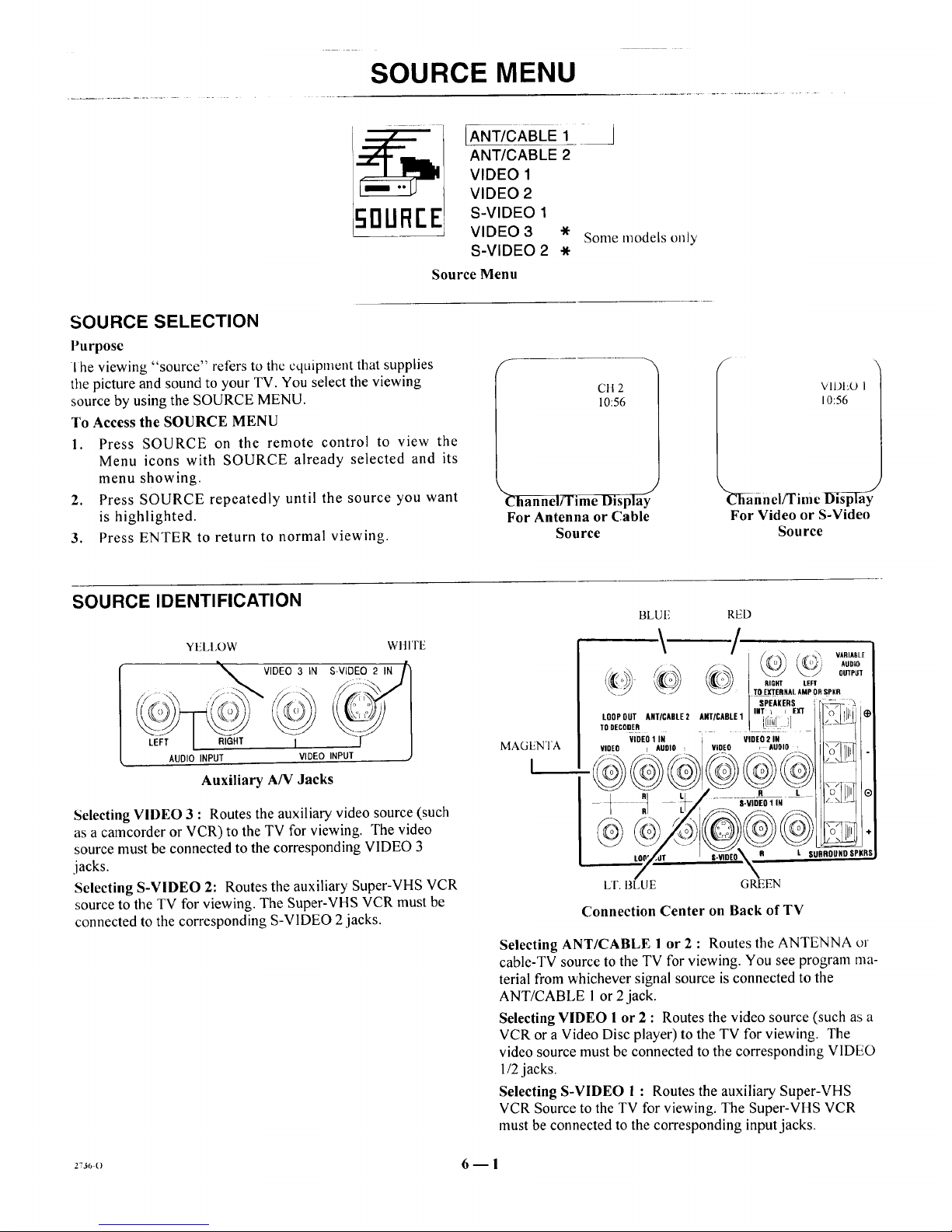
SOURCE SELECTION
Purpose
I he viewing "source" refers to the cquipment that supplies
the picture and sound to your TV. You select the viewing
source by using the SOURCE MENU.
To Access the SOURCE MENU
1. Press SOURCE on the remote control to view the
Menu icons with SOURCE already selected and its
menu showing.
2. Press SOURCE repeatedly until the source you want
is highlighted.
3. Press ENTER to return to normal viewing.
f
C1t2
10:56
_-fi_l;rrim e Display
For Antenna or Cable
Source
VIDEO 1
10:56
_Sahnci/Time Disp_ay
For Video or S-Video
Source
SOURCE IDENTIFICATION
YELI,OW WItlTE
_ VIDEO 3 IN S-VIDEO 2 IN /)
LE;F_T I RIGHT , INPUT [ J
AUDIO INPUT VIDEO
Auxiliar T AN Jacks
Selecting VIDEO 3 : Routes the auxiliary video source (such
as a camcorder or VCR) to the TV for viewing. The video
source must be connected to the corresponding VIDEO 3
jacks.
Selecting S-VIDEO 2: Routes the auxiliary Super-VHS VCR
source to the TV for viewing. The Super-VHS VCR must be
connected to the corresponding S-VIDEO 2 jacks.
MAGENTA
I
BLUF, RED
"_" '/" _ o\ VARIABLE
_J TO E)r[ERNAL AMP OR _pKR
SPEAKERS _ £2
lO0P0II'r ANTICADLE2 ANI/CAOIE1 I'_i',i: ',]E_ _.O_[[_ *
TDDECODER L U ::J . -"
VIDEO 1 IN
VIOEO r AUOIO
VIDEO
VIDEO 2 IN
, AUDIO 1
R L P, ILII 0
S-VIDEO1IN
#l l SLiRROtJNO SPKR8
LT. 13LUE GREEN
Connection Center on Back of TV
Selecting ANT/CABLE 1 or 2 : Routes the ANTENNA or
cable-TV source to the TV for viewing. You see program ma-
terial from whichever signal source is connected to the
ANT/CABLE l or 2jack.
Selecting VIDEO l or 2 : Routes the video source (such as a
VCR or a Video Disc player) to the TV for viewing. The
video source must be connected to the corresponding VIDEO
l/2 jacks.
Selecting S-VIDEO I : Routes the auxiliary Super-VHS
VCR Source to the TV for viewing. The Super-VHS VCR
must be connected to the corresponding input jacks.
2736O 6 -- I
Page 25

SETUP MENU
I o Access SE'I Ui"Menu
Refer to the "Using On-Screen
Menus" section for details.
Before Using SETUP Menu
Connect and turn ON all external
equipment, such as cable TV decoder,
VCR, etc. before using any item on
the SETUP Menu.
SETUP
[AUTO PROGRAM
CH. ADD/DEL
CH. LABELS
TUNING BAND
AUTO TUNING
SOURCE ID
CLOCK SET
CAPTIONS
Main Setup Menu
SETUP
ISOURCEID
CLOCK SET
CAPTIONS
Setup Menu for Video
and S-Video Sources
AUTO PROGRAM
Purpose
Finds all available channels and stores them in the memory of
the TV for use by CHANNEL (CH) Up/Down.
Use AUTO PROGRAM only when you first install your TV,
or when you permanently change the connections to the TV.
For example, when you replace the antenna with a cable-TV
system.
NOTE: AUTO PROGRAM can only be used with ANT/
CABLE 1 or 2 Source selection.
To Use AUTO PROGRAM
l°
2,
Press ADJUST (ADJ) Left/Right to start Auto Pro-
gram.
Use AUTO PROGRAM independently for each AN-
TENNA or CABLE signal source connected to your
TV. Select one source by using the SOURCE MENU
(ANT/CABLE 1 or 2) and use AUTO PROGRAM.
When completed, select the other source and use
AUTO PROGRAM again.
CH. (Channel) ADD/DEL
Purpose
Lets you add channels to and remove channels from the chan-
nel scan. Inthis way you can customize the channels that are
accessed through CHANNEL (CH) Up/Down.
NOTE: CH. ADD/DEL can only be used with ANT/CABLE
1or 2 Source selection.
To Add a Channel to Scan Sequence
I. Press ADJUST (ADJ) Left/Right to view the channel
add/delete screen.
2. Use the number buttons on the remote to enter the
channel or use ADJUST (ADJ) Left/Right and SE-
LECT Up/Down to move the highlight to the channel
you wish to add.
3. Add the channel by pressing SOURCE until the dis-
play shows ADDED.
/_UTOPROGRAM I [ SrART
CH.ADD/DEL
CH.LABELS
TUNINGBAND
AUTOTUNING
SOURCEID
CLOCKSET
CAPTIONS
Selecting Auto Program
When Some Channels Are Not Found
AUTO PROGRAM finds only active channels and stores
them in the favorite channel memory. You can add channels to
those stored in memory by using CH. ADD/DEL.
1 _ CH15ADD
LUTOPROGRAM
ICH.ADD/DEL
CH. LABELS
TUNING BAND
AUTO TUNING
SOURCE ID
CLOCKSET
CAPTIONS
Selecting Ch. Add/Del
To Delete a Channel from Scan Sequence
1. Press ADJUST (ADJ) Left/Right to view the channel
add/delete screen.
2. Use the number buttons on the remote to enter the
channel or use ADJUST (ADJ) Left/Right and SE-
LECT Up/Down to move the highlight to the channel
you wish to delete.
3. Delete the channel by pressing SOURCE until the
display shows DELETED.
(continued on next page)
7--1
.: 3(b o
Page 26

SETUP MENU
Available chamlels 10rCUllClltly
selected source.
Available channels are:
BROADCAST Band --
VHF 2 to 13, UHF 14 to 69
CATV, HRC and ICC Bands --
1 to 125
Use ADJUST Down to move
highlight to higher numbers.
1
7
13
19
25
31
37
43
49
55
61
67
73
79
85
2 3
8 9
14 [151
20 21
26 27
32 33
38 39
44 45
50 51
56 57
62 63
68 69
74 75
80 81
86 87
4 5 6
10 11 12
16 17 18
22 23 24
28 29 30
34 35 36
40 41 42
46 47 48
52 53 54
58 59 60
64 65 66
70 71 72
76 77 78
82 83 84
88 89 90
PRESS
SOURCETO
CHANGE
I
ADDED
CH 15
Channel Add/Delete Screen
Live view of curJcHtly
selected channel.
-----_ Instructions
Channel Status: Added to or t)c-
leted from channel scan.
I Currently selected channel.
CH. (Channel) LABELS
Purpose
Assigns a network label or "name" to the selected channels. If
you choose the label "ABC" for channel 15, "ABC" appears
in the Channel/Time display when channel 15 is selected for
viewing.
NOTE: CH. LABELS can only be used with ANT/
CABLE 1 or 2 Source selection. °._
A&E
BRAV
CNBC
DIS
EWTN
HN
MAX
NOS
REQ
TBN
TRAV
VCR
WWOR
ABC
CA
CNN
DISC
FAM
HSE
MEU
PBS
SC
TELE
TSN
VHI
YTV
ACTS
CBC
COM
E!
FNN
HSN
MMT
PLAY
SCFI
TLC
TVA
VISN
ADC
CBN
CSPN
ENC
FOX
IC
MTV
PTL
SHOW
TMC
TWN
VJN
AMC BET
CBS CMTV
CTN CTV
ESPN ET
GALA HBO
INSP LIFE
NBC NICK
QVC RDS
SIN TBS
TNN TNT
USA VC
WGN WTBS
Available Channel Labels
AUTO PROGRAM
OH. ADD/DEL
C[C-H.LABELS
TUNING BAND
AUTOTUNING
SOURCE ID
CLOCKSET
CAPTIONS
] { CH2ABC
Selecting Ch. Labels
To Use CH. LABELS
1. Press ADJUST (ADJ) Left/Right to view the chamlcl
label screen.
2. Use ADJUST (ADJ) Left/Right and SELECT
Up/Down to move the highlight to the LABEL you
wish to assign to the current channel.
3. To label another channel, use CHANNEL Up/Down,
or the number keys on the remote control to select the
channel number and repeat step 2.
4. To remove an assigned channel label, select the four
dashes.
Available channel
labels.
m
AMC
CBN
COM
DISC
EWTN
HBO
INSP
MTV
PLAY
SC
TBN
TNT
USA
VJN
A&E ABCj ACTS ADC
BET BRAV CA CBC
CBS CMTV CNBC CNN
CSPN CTN CTM DIS
E! ENC ESPN ET
FAM FNN FOX GALA
HN HSE HSN IC
LIFE MAX MEU MMT
NBC NICK NOS PBS
PTL QVC RDS REQ
SCFI SHOW SIN TBS
TELE TLC TMC TNN
TRAV TSN TMA TWN
VC VCR VH1 VISN
WGN WTBS WWOR YTV
LABEL
FOR
CH 15 '
Channel Label Screen
Live view of currently
selected channel.
Currently selected channel.
27s6-o 7 m 2
Page 27

SETUP MENU
TUNING BAND
Purpose
Allows for setting the TV channel selector (,tul_er)to match
your antenna or cable-TV system.
If you are having difficulty tuning channels, the TUNING
BAND may have to be set manually to match your viewing
needs.
NOTE: TUNING BAND can only be used with ANT/
CABLE 1 or 2 Source selection.
AUTO PROGRAM
CH. ADD/DEL
CH. LABELS
TUNING BAND
AUTO TUNING
SOURCE ID
CLOCK SET
CAPTIONS
] [ CABLE-CAW
J
Selecting Tuning Band
To Use TUNING BAND
Press ADJUST (ADJ) Left/l_,ight to select the tuning hallo that
gives you the most channels:
• BROADCAST--is used for standard "over-the-air" broad-
casts.
• CABLE -- CATV is used for most standard cable-TV
(CATV) systems.
• CABLE-- HRC is used for cable-TV systems that use HRC
(Harmonically Related Carrier).
• CABLE -- ICC is used for cable-TV systems using ICC
(Incremental Coherent Carrier).
Available Channels per Band
The channels that are available in the broadcast and cable tun-
ing bands are shown below:
BROADCAST Band -- VHF 2 to 13, UHF 14 to 69
CATV, HRC and ICC Bands -- 1 to 125
AUTO TUNING
Purpose
Lets your TV compensate for variations in broadcast and
cable-TV frequencies.
_UTOPROGRAM
CH. ADD/DEL
CH. LABELS
TUNING BAND
AUTOTUNING
SOURCE ID
CLOCK SET
CAPTIONS
] I FIXED
Selecting Auto Tuning
If you are having difficulty tuning channels, the AUTO TUN-
ING may have to be set manually to match your viewing
needs.
NOTE: AUTO TUNING can only be used with ANT/
CABLE 1 or 2 Source selection.
To Use AUTO TUNING
PressADJUST (ADJ) Left/Right to select the mode of opera-
tion that gives you the most channels:
• FIXED is used to receive "over-the-air" TV stations, and
with many cable-TV systems.
• SEARCH is used only when the TV must search to find the
frequency being received, such as when used with certain
VCRs and video game controllers.
SOURCE ID
Purpose
Assigns a descriptive "name" to the input sources. For exam-
ple, the VIDEO 1 source may be named VCR. "VCR" now
appears in the source menu as a reminder that your VCR is
connected to VIDEO 1input jacks.
To Use SOURCE ID
1. Press ADJUST (ADJ) Left/Right to view the
SOURCE 1D screen.
2. Use SELECT Up/Down to select a SOURCE.
3. Use ADJUST (ADJ) Left/Right to select the desired
name for the source.
_UTOPROGRAM
CH. ADD/DEL
CH. LABELS
TUNING BAND
AUTOTUNING
SOURCE ID
CLOCK SET
CAPTIONS
] [ LABEL
Selecting Source ID
(continued on next page)
2_6-o 7 _ 3
Page 28

SETUP MENU
Available
sources
SOURCE LABEL
ANTENNA
ANTICABLEI
ANTICABLE2 GABLE
EdT • vcR11117]
i(ai 52- .J
S-VIDEO1 LASERDISK
Source ID Screen
f
J
Live vie_v ol cm_cntly
selected source.
Optional names for AN 1/
CABLE 1 or 2 Sources arc:
ANTENNA, CABLE,
CABLE BOX,
SATELLITE.
Optional names for VIDEO
Sources are:
VCR, CAMCORDER, VIDEO
DISK, VIDEO GAME.
CLOCK SET
Purpose
Sets the clock in the TV to thc correct time.
AUTO PROGRAM
OH. ADD/DEL
CH. LABELS
TUNING BAND
AUTO TUNING
SOURCE ID
[OLOCK SET
CAPTIONS
] [ 10:00AM
Selecting Clock Set
To Use CLOCK SET from Remote Control
Use the numbered buttons on the remote control to enter the
current time. Press ENTER (ENT) to start the clock. Press
TIMER to select AM or PM.
To Use CLOCK SET from Control Panel
Use ADJUST (ADJ) Left/Right to set the time. Press ENTER
(ENT) to start the clock.
Channel/Time Display
CAPTIONS
Purpose
Displays closed captions (CC) or informational text when
available on the selected channel.
To Use CAPTIONS
Press ADJUST (ADJ) Left/Right to select desired mode of op-
eration. Five different selections can be made: OFF, CAP-
TION 1, CAPTION 2, TEXT I or TEXT 2.
_UTOPROGRAM
CH. ADD/DEL
CH, LABELS
TUNING BAND
AUTOTUNING
SOURCE ID
CLOCK SET
CAPTIONS
-J I CAPTION 1
Selecting Captions
At the time of this writing, very little appears in ally selection
except CAPTION 1.Therefore you should choose CAPTION
1and leave it in that selection unless you know there is some-
thing available in one of the other options. Once you make a
selection, that selection is remembered until you change it.
Hello! Areyou
outthere?
Typical Captions Display
Captions may be shown
anywhere on the screen.
Typical Text Display
Fixed size text window.
May be all black when no
information is shown.
_736-o 7_4
Page 29

AUDIO MENU
TREBLE
AUDIO
RUrlln[ SEO
SURROUND
BASS
TREBLE
BALANCE
AUDIO
(AUDIO mode options
are not available while
using a VIDEO or
S-VIDEO source. The
audio received from
these sources are
assumed to be stereo .)
Adjusts tile BASS (low-frequency) level.
Adjusts the TREBLE (high-frequency) level.
Adjusts the balance of sound between the left and right speakers for stereo programs.
Allows you to select STEREO, MONO or 2ND AUDIO/SAP speaker operation.
STEREO: Directs the sound to the left and right speakers as supplied by the program
source (broadcast TV, VCR, etc.)
MONO: Directs the same sound to both left and right speakers even if the source being
received is in stereo.
2ND AUDIO/SAP: Directs the sound for the Second Audio Program to both the left and right
speakers. SAP sound is always monaural. If the SAP signal ends, the audio
defaluts to either stereo or mono depending on the audio being received.
SEQ
(Spatial Equalization)
SURROUND
Improves tonal balance and increases apparent stereo separation to produce a spacious and more tonal
sound. SEQ is only available if a stereo signal is being received and STEREO is either selected using
the AUDIO option or selected by default.
Adjusts the level of Surround Sound provided to the optional surround sound speakers. Surround
Sound is only available if a surround encoded stereo signal is being received and STEREO is either
selected using the AUDIO option or selected by default.
To Access AUDIO MENU
Refer to the "Quick Reference to On-Screen Menus" section
for details.
NOTE: All adjustments on the AUDIO MENU are optional.
You do not have to use these features in order to use your TV.
Audio Mode Shown in
Channel/Time Display
STEREO is selected and a stereo
signal is being received. You will
hear stereo sound.
To Adjust BASS, TREBLE, BALANCE and SURROUND
Press ADJUST (ADJ) Left/Right until the most pleasing
sound is heard.
To Use AUDIO Mode Options
Press ADJUST (ADJ) Left/Right to select desired option.
We recommend that you use the STEREO option. The TV
will switch automatically between the STEREO and MONO
modes dependent on the signal being received.
If you prefer SAP, use the 2ND AUDIO/SAP option. On those
stations which broadcast two audio portions, you will hear the
SAP (usually a second language). When the SAP broadcast
ends, the TV switches automatically between STEREO and
MONO modes. The TV switches back to 2ND AUDIO/SAP
when the SAP broadcast resumes.
Page 30

VIDEO MENU
• I [CONTRAST
il,_I_B E ! TINTSHARPNESSCOLORBRIGHTNESS
COLOR TEMP
VIDEO FILTER
AUTO FLESH
PICTURE PREF
CON IKAS 1
BRIGHTNESS
COLOR
TINT
SHARPNESS
COLOR TEMP
VIDEO FILTER
AUTO FLESH
PICTURE PREF. (Pref-
erence)
Adjusts the overall contrast and color level of the picture.
Adjusts the brightness level of black areas in the picture.
Adjusts the intensity of the colors in the picture.
Adjusts the color of the flesh tones, where G is Green and R is Red.
Adjusts the clarity of the edges of objects for the clearest picture quality.
Changes the "color temperature" or picture white balance between cooler natural whites and wamler
(red) colors.
Reduces video "noise" or interference in dark picture areas resulting in clearer overall pictures.
Automatically maintains natural skin tones under changing scene and video source conditions.
Lets you decide if you want to use your own CUSTOM video settings, the factory PRESET video
settings, or the factory preset THEATER video settings for low light conditions.
To Access VIDEO Menu
Refer to the "Using On-Screen Menus" section tbr details.
Optional Adjustments
All adjustments on the VIDEO MENUS are optional. You do
not have to use these features in order to use your TV.
To Use Video Settings
1. Select video option to be adjusted.
2. Press ADJUST (ADJ) Left/Right until the most pleas-
ing picture is seen.
To Use PICTURE PREF. (Preference)
Press ADJUST (ADJ) Left/Right to select status.
If either the PRESET or THEATER setting is selected, any ad-
justment made to the VIDEO Menu options automatically
changes the PICTURE PREF. setting to custom, and saves
your current video settings in the CUSTOM mode.
27s6-o 9 - 1
Page 31

PIP MENU
1o Access PIP Menu
Refer to the "Using On-Screen
Menus" section for details.
NOTE: Selecting the PIP Menu does
not "activate" PIP. However, a PIP
inset will appear during menu opera-
tion to show the effect of any setting
changes.
PIP
ICH. GUIDE
CH. REVIEW
PIP SOURCE
PIP COLOR
PIP TINT
PIP SIZE
1
! Some models only
OH. (Channel) GUIDE
Purpose
Provides a visual review of all channels in the channel scan
memory forthe currently selected ANT/CABLE source.
To Use CH. GUIDE
1. Press ADJUST (ADJ) Left/Right to start Ch. Guide.
2. The TV will show small PIP-like views of all chan-
nels in the channel scan from the lowest channel
number to the highest.
3. Tune to a desired channel by pressing ENTER (ENT)
while the picture in the PIP-like inset is active, or
enter the channel number using the number keys on
the remote.
4. Press MENU to return to the PIP Menu.
CH.GUIDE
OH.REVIEW
PIPSOURCE
PIPCOLOR
PIPTINT
PIPSIZE
] [ START
Selecting Ch. Guide
CH 2 CH 3
CH 5
GH 7
CH 6
CH 9
Ch. Guide Screen
2,J_-,, 10- I
Page 32

PIP MENU
CH. (Channel) REVIEW
Purpose
I'rovides a visual review of the last three (3) channels tuned on
the TV.
To Use Ch. Review
I. Press ADJUST (ADJ) Left/Right to start Ch. Review.
2. The TV will show small PiP-like views of the last
three channels that were tuned.
3. Tune to a desired channel by pressing ENTER (ENT)
while the picture in the PIP-like inset is active, or
enter the channel number using the number keys on
the remote.
H.GUIDE
ECH.REVIEW
PIPSOURCE
PIPCOLOR
PIPTINT
PiPSIZE
J i START
Selecting Ch. Review
4. Press MENU to return to the PIP Menu.
CH 2
CH 5
I
CH 7
Ch. Review Screen
PIP SOURCE
Purpose
l,ets you select the equipment that supplies the pmcture to the
P1P inset.
To Use PIP SOURCE
Press ADJUST (ADJ) Left/Right to toggle through your
source options.
NOTE: If you "named" your sources (see SOURCE ID in
the SETUP MENU section), these names will appear when
toggling through the PIP SOURCE options.
CH.GUIDE
CH.REVIEW
PIPSOURCE
PIPCOLOR
PIPTINT
PIPSIZE
; L VIDEO 1
J
Selecting PIP Source
273_,-o I0 --2
Page 33

PIP MENU
PIP COLOR
Purpose
Adjusts the intensity of the colors in tile PIP inset.
To Use PiP COLOR
Press ADJUST (ADJ) Left/Right to decrease or increase the ill-
tensity of colors in the PIP inset.
CH.GUIDE
CH.REVIEW
PIPSOURCE
PIPCOLOR
PIPTINT
PIPSIZE
¥
Selecting PIP Color
PIP TINT
Purpose
Adjusts the color of the flesh tones.
To Use PIP TINT
If flesh tones are too red or purple, press ADJ U ST (ADJ) Left
until you acheive the desired flesh tone.
If flesh tones are too green or have a greenish TINT, press AD-
JUST (ADJ) Right until you acheive the desired flesh tone.
4.GUIDE
OH.REVIEW
PIPSOURCE
PIPCOLOR
-P_ TINT
PIPSIZE
__! R
__J
Selecting PIP Tint
PIP SIZE
Purpose
Lets you choose between seeing a larger or smaller PIP inset.
To Use PIP SIZE
Press ADJUST (ADJ) Left/Right to select either SMALLER
or LARGER.
H.GUIDE
H.REVIEW
IPSOURCE
IPCOLOR
Selecting PIP Size
Page 34

PIP OPERATION AND CONNECTIONS
PIP (PICTURE-IN-PICTURE) OVERVIEW
Your Zenith TV nmst be connected to a video component
such as a VCR in order to view a different picture in the PlP
inset. This video component must be connected to one of the
TV's video/audio input jacks (VIDEO I IN or VIDEO 2 IN)
by using Audio/Video cables.
The most common use of PIP is to view two diflercm chan-
nels; one from the TV tuner and the other from the VCR tune_.
For example, you can view two sporting events or two movies
at the same time.
TYPICAL CONNECTIONS
Option 1: Antenna or Direct Cable Connection
This illustration shows the basic connection of your TV to a
stereo VCR. Using this connection, you arecapable of the fol-
lowing operation:
• You may select ANT/CABLE 1 for main picture source to
view channels tuned by the TV's channel selector.
Simultaneously, you may select VIDEO 1 for PIP source to
view -- in the PIP inset -- a tape playing in the VCR or a
different channel tuned by the VCR's channel selector.
(VCR's TV/VCR button must be set to TV.)
Sources may also be swapped. In other words, VIDEO 1 ma},
be the main picture source and ANT/CABLE 1 the PiP
source.
Connection From Antenna
or Cable-TV System
(___) STEREO VCR
PIP InsetSource
_ICABLE 2
Connected to the VIDEO 1 IN jacks
(video and audio) on back of TV.
LOOPOUT
Main Picture bourcc
Connected to the ANT/CAt3LIs I
__I jack on back of TV.
/2<
\_] RIGHT LIFT
TO EXTERNALAMPORRPKR
SPEAKERS _7"
ANT/CABLE1 IN_rliEXT iO_j_ (_
woEo-ii,_
VIDEO r AUDIO I _/_
S-VInE0 R L SURROUNDSPKRS
Option I: Antenna or Direct Cable Connection
(continued on next page)
2736-0 11 -- 1
Page 35

PIP OPERATION AND CONNECTIONS
Option 2: Antenna or Direct Cable Connection Loop Out
This illustration shows the basic connection of your TV to a
stereo VCR. Using this connection, you arecapable of the fol-
lowing operation:
• You may select ANT/CABLE 2 for main picture source to
view channels tuned by the TV's channel selector.
Simultaneously, you may select VIDEO 1for PIP source to
view -- in the PIP inset m a tape playing in the VCR or
ANT/CABLE 1 to view a different channel tuned by the
VCR's channel selector. (VCR's TV/VCR button must be
set to TV and TV must be tuned to channel 3 or 4.)
Sources may also be swapped: VIDEO I may be the lna._
picture and ANT/CABLE 1 the PIP inset; or ANT/
CABLE 2 may be the main picture and ANT/CABLE 1 thc
PIP inset.
_OJli;c_:tioh From Antelllia
or Cable-TV System
STEREO VCR
)ANT IN ANT OUT
VIDEO R AUSI _
T
PIP Inset Source
Connected to the VIDEO 1INjacks
(video andaudio) on back of YV.
LOOPOUT
Option 2: Antenna or Direct Cable Connection Loop Out
Page 36
PIP OPERATION AND CONNECTIONS
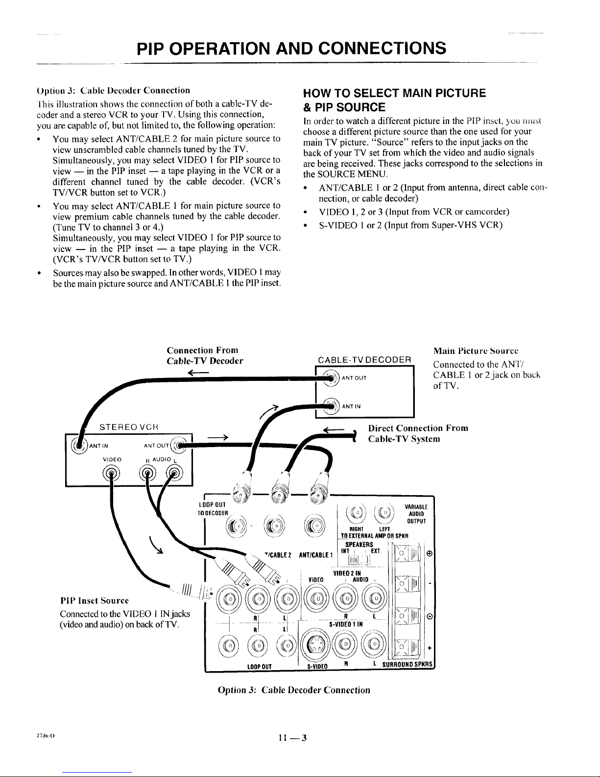
Option 3: Cable Decoder Connection
]'his illustration shows the connection of both a cable-TV de-
coder and a stereo VCR to your TV. Using this connection,
you are capable of, but not limited to, the following operation:
• You may select ANT/CABLE 2 for main picture source to
view unscrambled cable channels tuned by the TV.
Simultaneously, you may select VIDEO 1 for PIP source to
view -- in the PIP inset -- a tape playing in the VCR or a
different channel tuned by the cable decoder. (VCR's
TV/VCR button set to VCR.)
• You may select ANT/CABLE 1 for main picture source to
view premium cable channels tuned by the cable decoder.
(Tune TV to channel 3 or 4.)
Simultaneously, you may select VIDEO 1for PIP source to
view -- in the PIP inset -- a tape playing in the VCR.
(VCR's TV/VCR button set to TV.)
• Sources may also be swapped. In other words, VIDEO 1may
be the main picture source and ANT/CABLE 1 the PIP inset.
HOW TO SELECT MAIN PICTURE
& PIP SOURCE
In order to watch a different picture in the PIP inset, you mu,q
choose a different picture source than the one used for your
main TV picture. "Source" refers to the input jacks on the
back of your TV set from which the video and audio signals
are being received. These jacks correspond to the selections in
the SOURCE MENU.
• ANT/CABLE 1 or 2 (Input from antenna, direct cable con-
nection, or cable decoder)
• VIDEO 1, 2 or 3 (Input from VCR or camcorder)
• S-VIDEO I or 2 (Input from Super-VHS VCR)
Connection From Main Picture Source
Cable-TV Decoder CABLE-TV DECODER
Connected to the ANT/
<----- I ant our CABLE 1 or 2 jack on back
of TV.
ANT IN
STEREOVCR _ I _ • Direct Connection From
"---- s-R] _ H _ _ Cable-TV System
'ANTIN ANTOUT_ II__f_m_._
0+0,o,I /
S-
i
1 T IHT I _ EXT 0 I
I i ViOEO2IN "
_i_ I I VIDEO r AIJDIO + __;7_1
PIP Inset Source
Connected to the VIDEO 1 INjacks t _o--_ G
(video and audio) on back ofq_. ---RRt _ " S-VIDEO1 IN _ L
, © Lllill ÷
LOOP OUT S-VIDEO R L SURROUND SPKRS
Option 3: Cable Decoder Connection
2736-0 1 1 -- 3
Page 37
PIP OPERATION AND CONNECTIONS
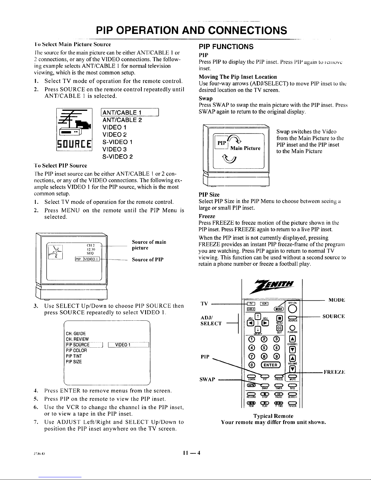
Io Select Main Picture Source
l'he source forthe main picturecan he eitherANT/CABLE 1 or
2 connections, or any of the VIDEO connections. The follow-
ing example selects ANT/CABLE 1 for normal television
viewing, which is the most common setup.
I. Select TV mode of operation for the remote control.
2. Press SOURCE on the remote control repeatedly until
ANT/CABLE 1 is selected.
IANT/CABLE 1 I
ANT/CABLE 2
VIDEO 1
VIDEO 2
5nUR[E S-V,DEOI
VIDEO 3
S-VIDEO 2
To Select PIP Source
l'lle PIP inset source can be either ANT/CABLE 1 or 2 con-
nections, orany of the VIDEO connections. The following ex-
ample selects VIDEO 1for the PIP source, which is the most
common setup.
1. Select TV mode of operation for the remote control.
2. Press MENU on the remote until the PIP Menu is
selected.
CII 2 ')
12:30 |
SEQ l
IPIPIVIDEOI H-- _--
!
Source of main
picture
Source of PIP
3°
Use SELECT Up/Down to choose PIP SOURCE then
press SOURCE repeatedly to select VIDEO 1.
f
CH.GUIDE
OH.REVIEW
_P_®Rcu ]
PIPCOLOR
PIPTINT
PIPSIZE
[ VIDEO1
4. Press ENTER to remove menus from the screen.
5. Press PIP on the remote to view the PIP inset.
6. Use the VCR to change the channel in the PIP inset,
or to view a tape in the PIP inset.
7. Use ADJUST Left/Right and SELECT Up/Down to
position the PiP inset anywhere on the TV screen.
PIP FUNCTIONS
PIP
Press PIP to display the PIP inset. Press PiP again to _cmuvc
inset.
Moving The Pip Inset Location
Use four-way arrows (ADJ/SELECT) to move PIP inset to the
desired location on the TV screen.
Swap
Press SWAP to swap the main picture with the PIP inset. Press
SWAP again to returnto the original display.
[_-_ai n Picture
Swap switches the Video
from the Main Picture to the
PIP inset and the PIP inset
to the Main Picture
PIP Size
Select PIP Size in the PIPMenu to choose betweeu seeing a
large or small PIP inset.
Freeze
Press FREEZE to freeze motion of the picture shown inthe
PIPinset. Press FREEZE again to return to a live PIPinset.
When the PIP inset is not currently displayed, pressing
FREEZE provides an instant PIP freeze-flame of the program
you arewatching. Press PIP again to return to normal TV
viewing. This function can be used without a second source to
retain a phone numberor freeze a football play.
TV
ADJ/ q
SELECT
PIP
SWAP --
QUiT FLASHBK
®®®
@®@
LEARN PIP FREEZE MUTE
SWAP TIMER SEO
_ OD CZD O
RECORD STOP PAUSE SEARCII
(33:> C]D (IE_ CZ_
REW PLAY F FWO TVNCR
MODE
SOURCE
FREEZE
Typical Remote
Your remote may differ from unit shown.
273_,-o 11 -- 4
Page 38

MAINTENANCE AND TROUBLESHOOTING
CARING FOR YOUR TV
Your TV will look better, have a longer life and perlb='mbetter
if you care for it properly.
First check to see that the TV is off. For added
_ afety, unplug the TV from the power outlet.
NOTE: If you unplug your TV, you will have to
reset the clock to the current time.
Cabinet Care
Non-Wood Cabinet or Cabinet Components.
Moisten a soft cloth with a mild soap solution or Ivory dish-
washing detergent. Wipe the surface with a damp cloth. Then
rinse the cloth in clean water and wipe the surface again. Al-
low the TV to air-dry before turning it on.
Picture Glass Cleaning
The picture tube face attracts dust particles and should be
cleaned regularly. To clean the face, spray a small amount of
glass cleaner on a cleaning cloth and wipe the picture tube
glass face until clean. Repeat if necessary.
To delay new dust accumulation, wet a soft cloth in lukewarm
water in which a little fabric softener or Ivory dishwashing de-
tergent has been mixed. Wring the cloth almost dry. Wipe the
glass face. Make sure no drops of moisture are squeezed onto
the glass. Do not wipe the glass dry. Allow the glass to air-dry
before you turn the TV on again.
Wood Cabinets or Cabinet Components.
Use any good fumiture cleaner and polish. Regular care will
help preserve the finish.
EXTENDED ABSENCE
Before an extended absence (such as a vacation) you may
want to unplug the power cord from the electrical wall outlet.
This will protect the TV from possible damage from lightning
or power line surges. If you have an outdoor antenna, you may
also want to disconnect the antenna lead-in wires on the back
of the TV.
NOTE: If you unplug your TV, you will have to resct tile
clock to the current time.
TV PICTURE INTERFERENCE
Your TV picture may be affected by interference caused by
one or a number of factors. These include:
Nearby Automobile Ignition, Electrical Appliances, etc.
Which causes a speckled, streaked picture. This is most notice-
able in weak signal areas.
Snow in Picture Caused by insufficient signal. Usually
caused by the TV being located too far from the TV station or
by an improper antenna installation.
Ghosts or Reflections Caused by signals being rcllcctcd
from surrounding buildings, water tanks, or other high struc-
tures.
Radio Signal Police, amateur or CB radio transmitters may
cause interference.
These interference problems can often be corrected through
the use of a better antenna, signal amplifiers, or various filter
devices. See your TV dealer for additional information, and
available TV accessories.
c_c.._m:2 12- I
Page 39

MAINTENANCE AND I HOUBLESHOO] INL5
BEFORE CALLING FOR SERVICE
Check these items and see if you can correct the trouble by
changing the adjustment of a control or the setting of a switch.
By making these simple checks before calling loL:,c_wcL_: ....
may save time and money.
Problem
Picture OK. Poor sound.
Sound OK. Poor picture.
No picture or sound.
Picture blurredl ghost in picturel Or distorted.
No Color, or poor color.
No sound.
Cannot select certain channels.
Remote control does not work.
No closed captions.
Black or blue box covers one half of the screen.
No picture or sound when VCR source is selected.
No sound or weak stereo sound when using a stereo VCR.
PIPis black when using VCR for PIP source.
PIP lacks contrast when using VCR for PIP source.
PIP inset frame is snowy when using TV tuner for PIP and
VCR for main picture.
Try This
Re-orient antenna. Try another channel -- possible station
trouble. Check for local interference. Check AUTO TUNING
and TUNING BAND options.
Re-orient antenna. Try another channel -- possible station
trouble. Adjust VIDEO Menu options with PICTURE PREF.
in CUSTOM mode.
Is TV on? Is there power in wall outlet? Is TV plugged in? Is
antenna hooked up? Is cable hooked up? ls cable operational?
Check auxiliary audio/video equipment. Check channel
selection. Check TUNING BAND and AUTO TUNING
Menu options.
Check antenna or cable hook up for broken wires or loose
connection. Try another channel -- possible station trouble.
Check for local interference.
Try another channel -- possible black and white program.
Check antenna or cable hook up for broken wires or loose
connection. Adjust VIDEO Menu options with PICTURE
PREF. in the CUSTOM mode. Is it a color program?
VOLUME (VOL) setting may be too low. Check MUTE
button operation on remote control, if provided. Is Speaker
EXT/INT switch in EXT position?
Channels may be skipped in CH. ADD/DEL Menu option.
Check TUNING BAND and AUTO TUNING options.
Are batteries okay? Is TV turned ON? Is TV plugged in?
Are captions available? Is CAPTION 1 or 2 selected by using
the CAPTIONS option on the SETUP Menu.
Is text information available? ls TEXT 1 or 2 selected by
using the CAPT1ONS option on the SETUP Menu?
Is VCR hooked up properly? Are wires connected to VCR-
VIDEO 1/2 jacks on connection center?
Check AUDIO mode? Is it STEREO? Was stereo present
before selecting VIDEO 1/2 or S-VIDEO Source?
Is VCR hooked up properly? Are wires connected to the
VIDEO 1/2 input jacks on connection center? Is VCR selected
for PIP source?
Is VCR hooked up properly? Are wires connected to the
VIDEO 1/2 input jacks on connection center?
Is TV/VCR switch on VCR in the TV position?
Always lcqucsl that your technician use only genuine Zenith
exact replacement parts for continued quality and safety per-
formance. Keep your Zenith ALL Zenith.
NOTE: If your 'IV fails to respond to any othcl incim ._ca__
tion, you must reset the TV. Simply disconnect the AC powei.
Wait a few minutes, then reconnect the AC power.
27s6-o 12 --2
Page 40

PRODUCT REGISTRATION CARD
_ou could wm a full refund on your new Zenith product.
l,ook for the Product Registration Card on your new video
product.
Each month a drawing is held by Zenith from the completed
Product Registration Cards received during the preceding
month. Zenith will reimburse the winner for the full purchase
price of the product purchased.
In order to participate, simply complete and return the Product
Registration Card at once, even if you choose not to complete
the information and interests portion of the questionnaire.
The odds of winning the free drawing described above, de-
pend on the number of participants. Free drawing offer is
void in Canada and other places where restricted or prohib-
ited by law. Offer is void for Hotel/Motel and Institutional
models. Rental models are not eligible.
Product Card lost or misplaced?
The Product Registration Card furnished with your video prod-
uct is pre-printed with its Model and Serial numbers. Please
fill out the card and mail it at your earliest convenience. It is
imperative that Zenith know how to reach you promptly if we
discover a safety problem that would affect you. If the original
card has been lost or misplaced, you may use the replacement
card provided below. Either card will qualify you for the free
drawing, but you are limited to only one entry in the drawing.
Complete the card, place it in an envelope and mail it to:
Zenith Electronics Corporation
P. O. Box 173257
Denver, CO 80217-3257
Use the replacement Product Registration Card only if the
original card has been misplaced or lost.
PHOTOCOPY AND CUT ALONG DAStIED LINE
r ...................................................................
Zenith Product Registration Card
O Pleose Print Clearly or Type (_ Area Code Telephone
1. I_]Mr. 2.[_Mrs. 3. [[[] Ms. 4. r-] Miss J J I I J J J J--J
H5Z01-01
First Name Initial Last Name
IIIIIIIliilUil
Street
IIIIIIIIIlllll
City
IIIIIIIIIIIIII
State Zip Code
IIIIIIII1-11111
I I
I
I
IIII
I I I I I I I I I I I
Apt. No.
I I I I I I II I I I I
J Q Date of Purchase
Me. Day Yr.
I
I
Illlllill
Copy Numbers Here
From Label on Set
SERIAL _NUMBER
Please record the model number
and serial number from the sticker
on the back of your set.
I ......................................................................................................................... J
'1 V(TA RI)2
Page 41

BROKENORLOSTREMOTECONTROL?
Foran ExactReplacementRemote
Controlfor your newZenith Television,
seeyour localZenith Dealeror order
direct by calling 1-800-255-6790. To
assurethecorrectremote for your new
Zenith, pleasehaveyour television's model
and serial number and date of purchaseready!
ONLY$39.95
OTHERFINEACCESSORIESFORYOURTELEVISION.
WALLMOUNTS
(17 Ibs.)
• Easytoinstall 13"
• Safeandstrong
•5 yearwarranty
• Madein U.S.A. 19/20"
•Spacesaving
•UL listed
• Adjustabletiltangle: 25/27"
0to 12degrees
IfyourTV
screen is:
Order
this model
CWMO13 ONLY
$69.95
CWM020 ONLY
S89.95
CWM027 ONLY
$99.95
DELUXEAMPLIFIED 75 OHM
INDOOR TV ANTENNA.
• Provides sharp, clear pictures
• VHF/UHF color & FM stereo reception
• VHF/UHF signal combiner circuitry
• Includes:
• Matching transformer
• 4 ft. coaxial cable with connectors
• Designed and built in the U.S.A.
ATS 750 ONLY$59.95
PHOTOCOPYPAGEANDDETACHHERE
.......................................... q ................ _ ..........................................
Toorder thesefine accessories,
pleasefill out this card and
return a photocopy to:
Attn: Accessory Offers
Zenith Video TechCorporation
1900 N.Austin Avenue
Chicago,IL 60639
or call1-800-255-6790
[] Checkor money order
(MadepayabletoZenithVideoTechCorp.)
ITEMNUMBER
DESCRIPTION PRICEPERITEM
SUBTOTAL
CA73/4%,GA4%,IL83/4%,KS4.9%,KY6%,ME8%,
PA8%,RI7%,TX73/4%,VA41/2%,WA61/2%.
$4.50
SalesTax: Pleaseadd your statesalestax ifyou
live in oneof thefollowing states.
[] Visa [] Mastercard
Account#
I I I
ExpirationDate: Signature:
STATESALESTAX
SHIPPING& HANDLING
TOTALAMOUNTOFORDER
TOTAL
PRICE
SHIPTO:
Telephone:( )
Name:
IMPORTANT:PLEASEBESURETOCOMPLETETHEINFORMATIONBELOW.
/ /
TVModelNumber TVSerialNumber Mo. Day Yr.
(fromstickeronbackofunit) (fromstickeronbackofunit) (Approx.dateofpurchase.)
PLEASEALLOWUPTO3 WEEKSFORDELIVERY.THANKYOU!
Address:
Apt. #
State
City
ZipCode
NOTE:Priceandavailabilitysubjectto change.
TVACCS3
Page 42

YOUR ZENITH WARRANTY
Consumer Protection Plan for Zenith TV
Welcome into the Zenith family! We believe that you will be
pleased with your new Zenith Color TV. Please readthis Con-
sumer Protection Plan carefully. It is a "LIMITED WAR-
RANTY" as defined under Federal Law. This warranty gives
you specific legal rights, and you may also have other rights
that vary from state to state within the U.S.A.
Zenith's Responsibility
Service Labor --During a period of 90 days from effective
warranty date, Zenith will pay for service labor by a U.S. or
Canadian distributor-approved Zenith service center when
needed as a result of manufacturing defects.
Parts -- New or remanufactured replacements for factory-defec-
tive parts will be supplied by a U.S. or Canadian
distributor-approved service center for one year from effective
warranty date (color picture tube -- two years). Such replace-
ment parts are warranted for the remaining portion of the original
warranty period.
Home Service -- Warranty service for 19" diagonal (U.S.A.)
or larger screen size models is provided in the home.
Not Covered -- This warranty covers manufacturing defects
and does not cover installation, adjustment of customer con-
trols in the home, installation or repair of home antenna sys-
tems, cable converters or cable company-supplied equipment;
it also does not cover damage due to misuse, abuse, negli-
gence, acts of God or other causes beyond the control of
Zenith. Any alteration of the product after manufacture voids
this warranty in its entirety.
Owner's Responsibility
Effective Warranty Date -- Warranty begins on the date ot
original consumer installation. For your convenience, keep the
dealers dated bill of sale or delivery ticket as evidence of the
purchase date.
Operating Guide -- Read your Operating Guide carefully so
that you will understand the operation of your set and how to
adjust the customer controls.
Carry-In Service --Models under 19" diagonal (U.S.A.)
screen size must be taken to a distributor-approved Zenith
service center for warranty service and must be picked up by
the owner.
Antenna -- Reception problems caused by inadequate home
antennas or faulty antenna connections are the owner's respon-
sibility.
Important: Product Registration -- Please fill out and mail
your Product Registration Card. It is imperative that Zenith
know how to reachyou promptly if we should discover a
safety problem that could affect you.
Warranty Service -- For warranty service information, con-
tact your Zenith dealer preferably, or any distributor-
approved Zenith service center. Parts and service labor that are
Zenith's responsibility (see above) will be provided without
charge. Other service is at the owner's expense. If you have
any problem in obtaining satisfactory warranty service, write:
Zenith Electronics Corporation
Customer Service Department
1900 N. Austin Avenue
Chicago, Illinois 60639-5079
Telephone: (312) 745-5152
Mon-Fri, 8:00 a.m. - 4:30 p.m. Central Time
NOTE: Before you ask for Warranty service, check
the Operating Guide section entitled, "MAINTE-
NANCE AND TROUBLESHOOTING." It may be
possible to avoid a service call.
Page 43

1000 MILWAUKEE AVENUE
GLENVIEW, ILLINOIS 60025
i_.tl I.i,_u. ,.;'tJO-ZlJO
Printed in U.S.A.
EP-EDCBAO
 Loading...