

Page 1
MODEL : LST-5600A
MODEL : LST-5600ASERVICE MANUAL
HD Integrator Box
System
SERVICE MANUAL
CAUTION
BEFORE SERVICING THE UNIT, READ THE “SAFETYPRECAUTIONS”
IN THIS MANUAL.
Page 2

1-1
SECTION 1
SUMMARY
CONTENTS
INTRODUCTION ......................................................................................................1-2
PRODUCT SAFETY SERVICING GUIDELINES FOR VIDEO PRODUCTS............1-3
SERVICING PRECAUTIONS ....................................................................................1-4
SPECIFICATIONS.....................................................................................................1-5
Page 3

1-2
INTRODUCTION
- Digital/Analog broadcasting recorder/receiver [HD/SD PERSONAL VIDEO RECORDER & RECEIVER] or
PVR(Personal Video Recorder)-STB(Set-Top Box) receives the ground wave HD Digital broadcasting program /Analog NTSC or Cable broadcasting program and saves a video and audio signal at a HDD with a
specific form or offers additional related services..
- Configuration
The PCU is the IBM PPC405GP of the PowerPC series supporting PCI Bus I/F for PVR, and the tuner
receives a digital ground wave and transfers it as a TP signal, transmitting the NTSC signal of the ground
wave/the cable signal and transferring the audio signal to the SIF.
The MPEG Decoder uses the HD-II supporting MP@HL built with the AC-3 Decoder.
The PVR section transforms the TP data of a digital TV signal and an analog audio/video signal into the TP
by using the MPEG-II Encoder and saves only the necessary data to the HDD via the IDE I/F Chip.
Overall configuration
- System section
CPU, Main Memory, MPEG-II Decoder, Flash Memory, and System CPLD.
- MPEG Video/Audio Decoder section
HD-2, Memory, PLL IC, Audio Processor, Audio ADC, and so on.
- PVR section
TPN-II performing PCI I/F and TP De-Mux, Memory, MPEG-II Encoder, IDE I/F Chip, and 120GB HDD.
- Video/Audio input section
CVBS Decoder, and Audio processor
-1394 section
1394 1-Chip supporting D-VHS and MV Camcoder.
- Tuner
It can receive a signal from ATSC/NTSC/Cable, and send a signal from the ATSC as TP, an analog video signal as NTSC, and an audio signal as SIF.
- Front section
It is located at the front receiving various key inputs from users and displaying the status of a set-top box at
the VFD.
- Power section
It supplies a DC power to Main Digital Board, Front Board, and HDD with the input of AC 110V.
Page 4
1-3
IMPORTANT SAFETY NOTICE
This manual was prepared for use only by properly trained audio-video service
technicians.
When servicing this product, under no circumstances should the original
design be modified or altered without permission from LG Electronics
Corporation. All components should be replaced only with types identical to
those in the original circuit and their physical location, wiring and lead dress
must conform to original layout upon completion of repairs.
Special components are also used to prevent x-radiation, shock and fire hazard. These components are indicated by the letter “x” included in their component designators and are required to maintain safe performance. No deviations
are allowed without prior approval by LG Electronics Corporation.
Circuit diagrams may occasionally differ from the actual circuit used. This way,
implementation of the latest safety and performance improvement changes
into the set is not delayed until the new service literature is printed.
CAUTION: Do not attempt to modify this product in any way. Never perform
customized installations without manufacturer’s approval. Unauthorized modifications will not only void the warranty, but may lead to property damage or
user injury.
Service work should be performed only after you are thoroughly familiar with
these safety checks and servicing guidelines.
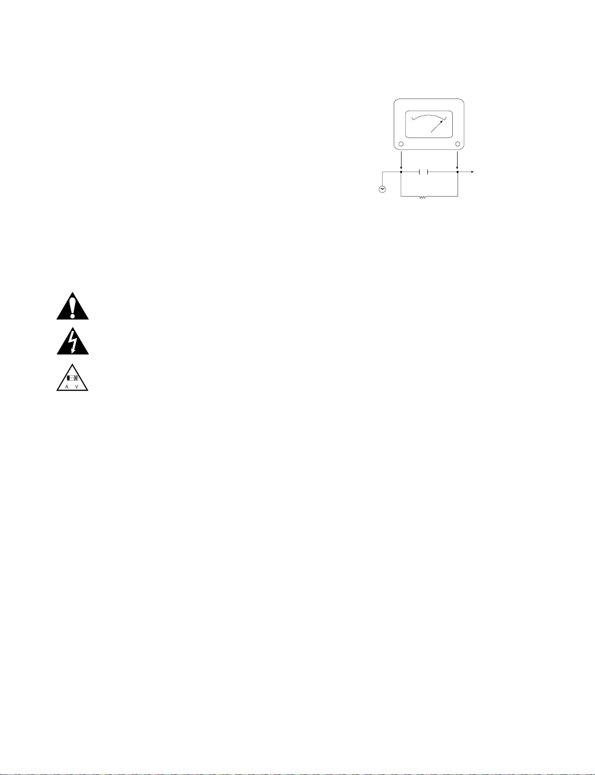
GRAPHIC SYMBOLS
The exclamation point within an equilateral triangle is intended to
alert the service personnel to important safety information in the
service literature.
The lightning flash with arrowhead symbol within an equilateral triangle is intended to alert the service personnel to the presence of
noninsulated “dangerous voltage” that may be of sufficient magnitude to constitute a risk of electric shock.
The pictorial representation of a fuse and its rating within an equilateral triangle is intended to convey to the service personnel the
following fuse replacement caution notice:
CAUTION: FOR CONTINUED PROTECTION AGAINST RISK
OF FIRE, REPLACE ALL FUSES WITH THE SAME TYPE AND
RATING AS MARKED NEAR EACH FUSE.
SERVICE INFORMATION
While servicing, use an isolation transformer for protection from AC line shock.
After the original service problem has been corrected, make a check of the following:
FIRE AND SHOCK HAZARD
1. Be sure that all components are positioned to avoid a possibility of adjacent
component shorts. This is especially important on items trans-ported to and
from the repair shop.
2. Verify that all protective devices such as insulators, barriers, covers, shields,
strain reliefs, power supply cords, and other hardware have been reinstalled
per the original design. Be sure that the safety purpose of the polarized line
plug has not been defeated.
3. Soldering must be inspected to discover possible cold solder joints, solder
splashes, or sharp solder points. Be certain to remove all loose foreign particles.
4. Check for physical evidence of damage or deterioration to parts and components, for frayed leads or damaged insulation (including the AC cord), and
replace if necessary.
5. No lead or component should touch a high current device or a resistor rated
at 1 watt or more. Lead tension around protruding metal surfaces must be
avoided.
6. After reassembly of the set, always perform an AC leakage test on all
exposed metallic parts of the cabinet (the channel selector knobs, antenna
terminals, handle and screws) to be sure that set is safe to operate without
danger of electrical shock. DO NOT USE A LINE ISOLATION TRANSFORMER DURING THIS TEST. Use an AC voltmeter having 5000 ohms per
volt or more sensitivity in the following manner: Connect a 1500 ohm, 10
watt resistor, paralleled by a .15 mfd 150V AC type capacitor between a
known good earth ground water pipe, conduit, etc.) and the exposed metallic parts, one at a time. Measure the AC voltage across the combination of
1500 ohm resistor and .15 mfd capacitor. Reverse the AC plug by using a
non-polarized adaptor and repeat AC voltage measurements for each
exposed metallic part. Voltage measured must not exceed 0.75 volts RMS.
This corresponds to 0.5 milliamp AC. Any value exceeding this limit constitutes a potential shock hazard and must be corrected immediately.
TIPS ON PROPER INSTALLATION
1. Never install any receiver in a closed-in recess, cubbyhole, or closely fitting
shelf space over, or close to, a heat duct, or in the path of heated air flow.
2. Avoid conditions of high humidity such as: outdoor patio installations where
dew is a factor, near steam radiators where steam leakage is a factor, etc.
3. Avoid placement where draperies may obstruct venting. The customer
should also avoid the use of decorative scarves or other coverings that
might obstruct ventilation.
4. Wall- and shelf-mounted installations using a commercial mounting kit must
follow the factory-approved mounting instructions. A product mounted to a
shelf or platform must retain its original feet (or the equivalent thickness in
spacers) to provide adequate air flow across the bottom. Bolts or screws
used for fasteners must not touch any parts or wiring. Perform leakage tests
on customized installations.
5. Caution customers against mounting a product on a sloping shelf or in a tilted position, unless the receiver is properly secured.
6. A product on a roll-about cart should be stable in its mounting to the cart.
Caution the customer on the hazards of trying to roll a cart with small casters across thresholds or deep pile carpets.
7. Caution customers against using extension cords. Explain that a forest of
extensions, sprouting from a single outlet, can lead to disastrous consequences to home and family.
PRODUCT SAFETY SERVICING GUIDELINES FOR VIDEO PRODUCTS
A.C. Voltmeter
Good Earth Ground
such as the Water
Pipe, Conduit, etc.
0.15uF
1500 OHM
10 WATT
Place this probe
on each exposed
metal part.
Page 5

1-4
SERVICING PRECAUTIONS
CAUTION: Before servicing the HD/SD PERSONAL VIDEO
RECORDER & RECEIVER WITH GEMSTAR covered by
this service data and its supplements and addends, read and
follow the
SAFETY PRECAUTIONS. NOTE: if unforeseen
circumstances create conflict between the following servicing precautions and any of the safety precautions in this publications, always follow the safety precautions.
Remember Safety First:
General Servicing Precautions
1. Always unplug the HD/SD PERSONAL VIDEO
RECORDER & RECEIVER WITH GEMSTAR AC power
cord from the AC power source before:
(1)Removing or reinstalling any component, circuit board,
module, or any other assembly.
(2) Disconnecting or reconnecting any internal electrical
plug or other electrical connection.
(3) Connecting a test substitute in parallel with an elec-
trolytic capacitor.
Caution: A wrong part substitution or incorrect
polarity installation of electrolytic capacitors may result
in an explosion hazard.
2. Do not spray chemicals on or near this HD/SD PERSON-
AL VIDEO RECORDER & RECEIVER WITH GEMSTAR
or any of its assemblies.
3. Unless specified otherwise in this service data, clean
electrical contacts by applying an appropriate contact
cleaning solution to the contacts with a pipe cleaner,
cotton-tipped swab, or comparable soft applicator.
Unless specified otherwise in this service data, lubrication
of contacts is not required.
4. Do not defeat any plug/socket B+ voltage interlocks with
which instruments covered by this service manual might
be equipped.
5. Do not apply AC power to this HD/SD PERSONALVIDEO
RECORDER & RECEIVER WITH GEMSTAR and / or any
of its electrical assemblies unless all solid-state device
heat sinks are correctly installed.
6. Always connect the test instrument ground lead to an
appropriate ground before connecting the test instrument
positive lead. Always remove the test instrument ground
lead last.
Insulation Checking Procedure
Disconnect the attachment plug from the AC outlet and turn
the power on. Connect an insulation resistance meter (500V)
to the blades of the attachment plug. The insulation resistance between each blade of the attachment plug and accessible conductive parts (Note 1) should be more than 1Mohm.
Note 1: Accessible Conductive Parts include Metal panels,
Input terminals, Earphone jacks,etc.
Electrostatically Sensitive (ES) Devices
Some semiconductor (solid state) devices can be damaged
easily by static electricity. Such components commonly are
called Electrostatically Sensitive (ES) Devices. Examples of
typical ES devices are integrated circuits and some field
effect transistors and semiconductor chip components.
The following techniques should be used to help reduce the
incidence of component damage caused by static electricity.
1. Immediately before handling any semiconductor component or semiconductor-equipped assembly, drain off any
electrostatic charge on your body by touching a known
earth ground. Alternatively, obtain and wear a commercially available discharging wrist strap device, which
should be removed for potential shock reasons prior to
applying power to the unit under test.
2. After removing an electrical assembly equipped with ES
devices, place the assembly on a conductive surface such
as aluminum foil, to prevent electrostatic charge buildup or
exposure of the assembly.
3. Use only a grounded-tip soldering iron to solder or unsolder
ES devices.
4. Use only an anti-static solder removal device. Some
solder removal devices not classified as “anti-static” can
generate electrical charges sufficient to damage ES
devices.
5. Do not use freon-propelled chemicals. These can
generate an electrical charge sufficient to damage ES
devices.
6. Do not remove a replacement ES device from its protective package until immediately before you are ready to
install it. (Most replacement ES devices are packaged with
leads electrically shorted together by conductive foam,
aluminum foil,or comparable conductive material).
7. Immediately before removing the protective material from
the leads of a replacement ES device, touch the protective
material to the chassis or circuit assembly into which the
device will be installed.
Caution: Be sure no power is applied to the chassis or
circuit, and observe all other safety precautions.
8. Minimize bodily motions when handling unpackaged
replacement ES devices. (Normally harmless motion such
as the brushing together of your clothes fabric or the lifting
of your foot from a carpeted floor can generate static electricity sufficient to damage an ES device.)
Page 6

1-5
SPECIFICATIONS
Dimensions
Height: 2.60 inches
Width: 14.17 inches
Depth: 11.54 inches
Weight: 6.8 lbs.
AC Power: AC 120V, 60Hz
Power Consumption 18W
Operating Conditions
Temperature: 32 to 122 degrees Fahrenheit (0 to 40 degrees Celsius)
Humidity: 95% non-condensing
Altitude: 7500 feet above sea level maximum
RF Input
Frequency Range: 50 to 800 MHz (Broadcast CH 2-69, Cable STD/IRC/HRC)
Connector: “F” type
Impedance: 75 Ohms
Video/Audio Inputs NOT PROVIDED
Control Inputs
MPI (On Superport card): RJ-11 Modular Jack
IR Receiver: Headphone type 3.5 mm jack.
Outputs
Video (Video reserved for factory use only)
Audio: RCA type
DVI-HDTV Video: DVI-HDTV type
Digital Audio: Digital Audio Out
Line Level Audio: Stereo Left/Right RCA jacks
Superport Card Slot Standard M.P.I. Card
Supplied Accessories RS-232C Cable
Audio Cable (RCA to 3.5 mm mini plug)
DVI Cable (DVI-HDTV type)
IR Receiver & Bracket
L-Brackets & Screws
Ferrite Core (2 EA)
AC Input/Outputs
Input: 120V ~ 60Hz, 7.3 Amps, 785 Watts
Output: 120V ~ 60Hz, Maximum 7 Amps, 750 Watts
Optional Accessories IR Bracket for 50” and 60” Plasma Displays
Plasma Wall Mount Brackets
Note: Design and specifications subject to change without prior notice.
Page 7

2-1
SECTION 2
CABINET & MAIN CHASSIS
CONTENTS
EXPLODED VIEWS.....................................................................................................................2-2
1. Cabinet and Main Frame Section...........................................................................................2-2
2. Packing Accessory Section ....................................................................................................2-3
Page 8

2-2
EXPLODED VIEWS
1. Cabinet and Main Frame Section
A
4
3
2
1
BCD
467
250
A46
NOTES) THE EXCLAMATION POINT WITHIN AN
EQUILATERAL TRIANGLE IS INTENDED
TO ALERT THE SERVICE PERSONNEL
TO THE PRESENCE OF IMPORTANT
SAFETY INFORMATION IN SERVICE
LITERATURE.
467
471
472
468
467
A47
273
272
471
467
262
263
A48E
271
465
274
275
264
468
472
468
469
261
320
A44
261
266
465
261
A48D
A48C
A48A
467
A48B
471
A48
330
266
465
Page 9

2-3
2. Packing Accessory Section
900
REMOCON
INSTRUCTION ASSEMBLY
801
PACKING (LF)
803
827
CABLE COAXIAL
826
FILTER(CIRC)
823
822
PACKING (RF)
803
DVI CABLE
D-SUB(RS23)
BAG
804
BOX CARTON
802
300
POWER COARD
Page 10

3-1
SECTION 3
ELECTRICAL
CONTENTS
ELECTRICAL TROUBLESHOOTING GUIDE ..................................................................................................3-2
1. Power(SMPS) CIRCUIT...........................................................................................................................3-2
2. CPU(SYSTEM CONTROL) TROUBLESHOOTING................................................................................3-4
3. ATSC/QAM FRONT_END TROUBLESHOOTING.................................................................................3-12
4. NTSC/FRONT_END TROUBLESHOOTING ..........................................................................................3-14
5. FPGA TROUBLESHOOTING ................................................................................................................3-15
6. VIDEO TROUBLESHOOTING ...............................................................................................................3-16
7. AUDIO TROUBLESHOOTING...............................................................................................................3-29
BLOCK DIAGRAM ..........................................................................................................................................3-38
1. OVERALL BLOCK DIAGRAM...............................................................................................................3-38
2. POWER BLOCK DIAGRAM ..................................................................................................................3-39
3. BLOCK DIAGRAM.................................................................................................................................3-40
CIRCUIT DIAGRAMS......................................................................................................................................3-41
1. POWER(SMPS) CIRCUIT DIAGRAM....................................................................................................3-41
2. CPU & SYSTEM MEMORY CIRCUIT DIAGRAM..................................................................................3-43
3. CPU PERI & IR-IN & AUX-CTRL CIRCUIT DIAGRAM.........................................................................3-45
4. TERRESTRIAL FRONT_END CIRCUIT DIAGRAM .............................................................................3-47
5. HD2 & SDRAM CIRCUIT DIAGRAM.....................................................................................................3-49
6. DVI TRANSMITTER CIRCUIT DIAGRAM .............................................................................................3-51
7. VDP I/F & DISPLAY OUTPUT CIRCUIT DIAGRAM ..............................................................................3-53
8. NTSC AUDIO PROCESSOR CIRCUIT DIAGRAM................................................................................3-55
9. POWER REGULATION CIRCUIT DIAGRAM ........................................................................................3-57
10. FPGA FOR DECRYOPTION CIRCUIT DIAGRAM ..............................................................................3-59
PRINTED CIRCUIT DIAGRAMS.....................................................................................................................3-61
1. DIGITAL MAIN PRINTED CIRCUIT DIAGRAMS(TOP).........................................................................3-61
2. DIGITAL MAIN PRINTED CIRCUIT DIAGRAMS(BOTTOM).................................................................3-63
3. MPI PRINTED CIRCUIT DIAGRAM(TOP).............................................................................................3-65
4. PTC PRINTED CIRCUIT DIAGRAM......................................................................................................3-67
5. BACK PLANE PRINTED CIRCUIT DIAGRAM......................................................................................3-69
6. POWER PRINTED CIRCUIT DIAGRAM................................................................................................3-70
Page 11
3-2
ELECTRICAL TROUBLESHOOTING GUIDE
NO
Check or Replace
the D102
Replace the D124
Replace the D125
Replace the D129
Replace the D126
YES
YES
Is the D129
Normal?
Is the D126
Normal?
YES
Power Line of Main
PCB is short
1. Power(SMPS) CIRCUIT
No 3.8VA
Replace the FR101
(Use the same ICW)
Is the F101
Normal?
Is the R107
Normal?
Is the BD101
Normal?
NO
NO
NO
NO
NO
NO
NO
NO
NO
NO
Replace the
BD101
Replace the R107
Is the D102
normal?
Replace the D121
Replace the IC103
YES
YES
YES
YES
YES
YES
YES
Is Vcc (14V-22V) supplied to IC101 Pin3?
Are the D121
normal?
Is there about 2.5V
at the IC103 Pin1?
Is the D124
normal?
Is the D125
Normal?
Page 12
3-3
No 5VA
Check or Replace
the D124
Is there about 5.5V
at the IC153 pin1?
Check or Replace
the IC153
NO
YES
YES
No 12VA
Check or Replace
the D129
Is there about 14V
at the IC151 pin1?
Check or Replace
the IC153
NO
YES
YES
No 30VA
Replace the ZD152
(Use the same Value)
Is the ZD152
Normal?
Check or Replace
the D126
NO
YES
YES
Page 13

3-4
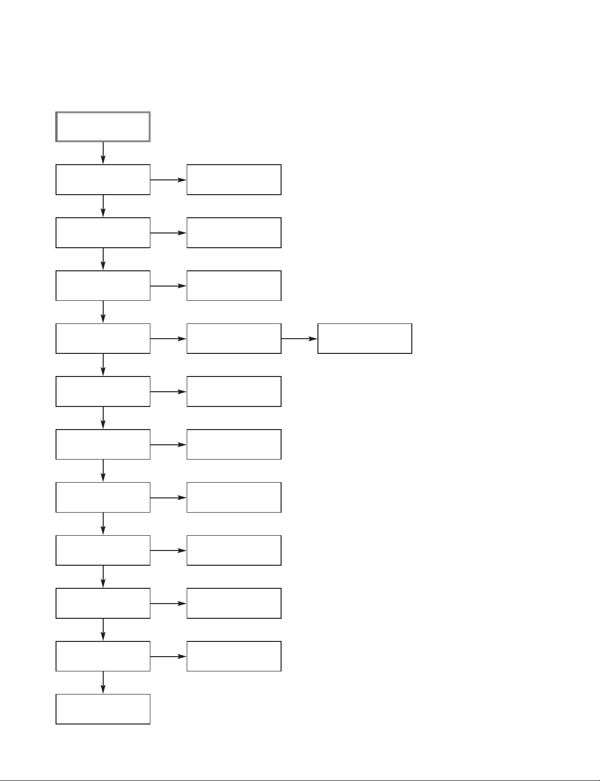
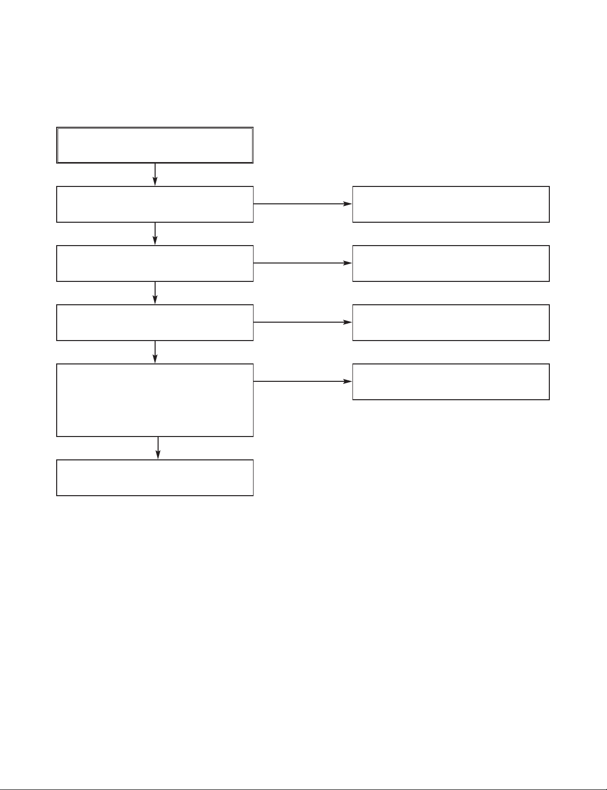
2. CPU(SYSTEM CONTROL) TROUBLESHOOTING
Start
Power is supplied normally?
YES
NO
Clock signals are OK?
YES
Reset signals are OK at the time of
power-on reset?
Chip selection signals are OK?
IIC channels are OK?
YES
YES
YES
Interrupt signals are OK?
Messages are output through
RS-232C port on PC terminal?
END
YES
YES
YES
NO
(B) Clock check
(A) Power check
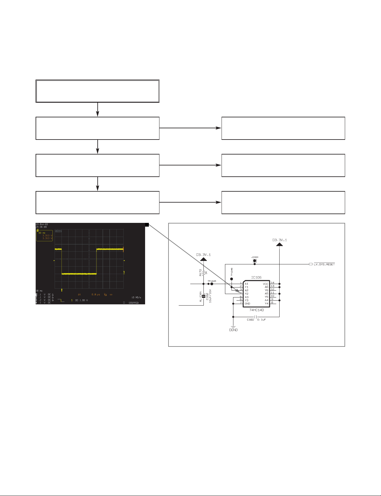
(C) Reset check
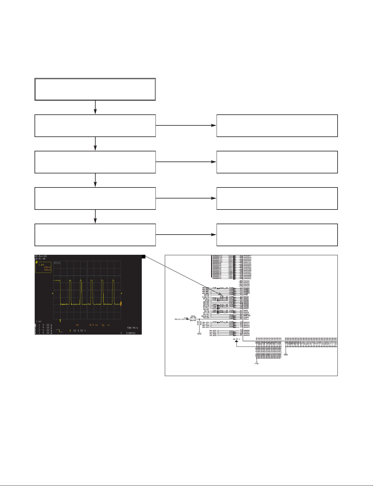
(D) CS check
(E) IIC check
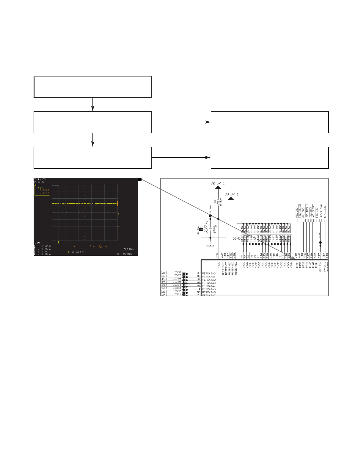
(F) Interrupt check
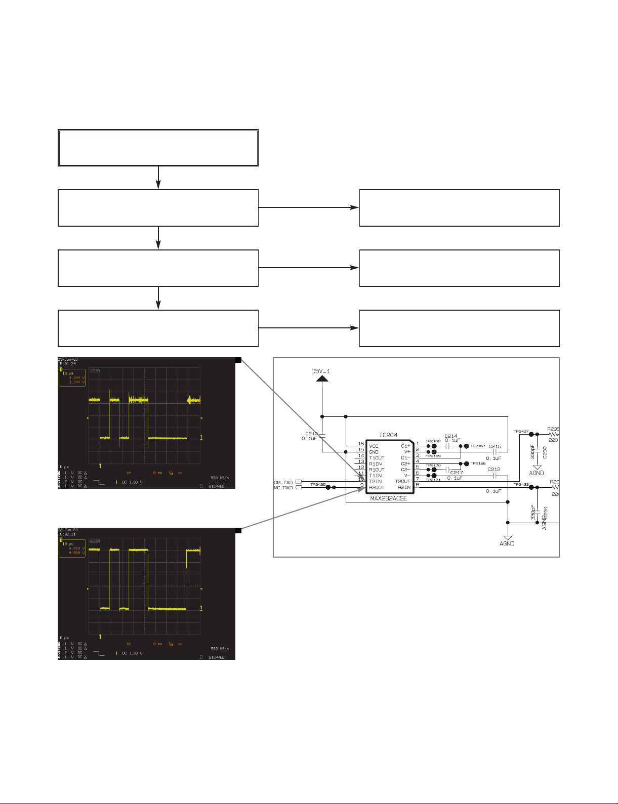
(G) RS-232C check
NO
NO
NO
NO
NO
Page 14

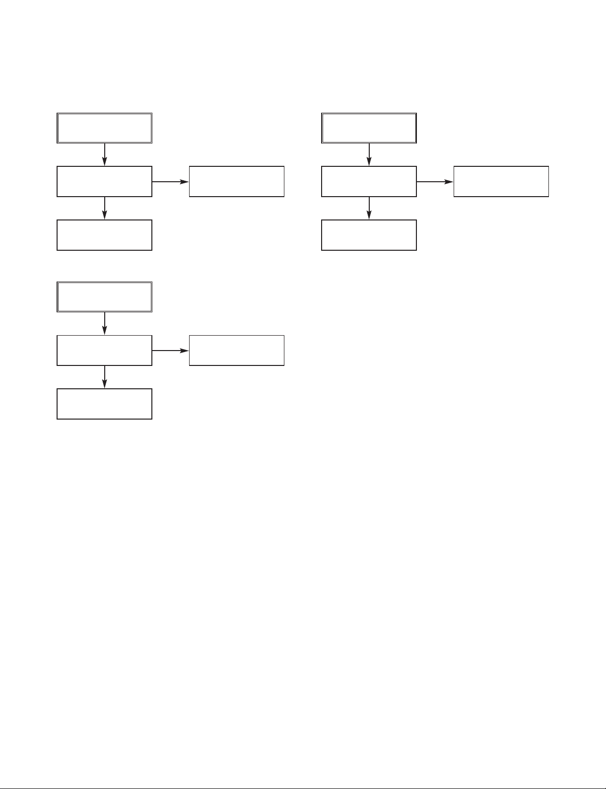
3-5
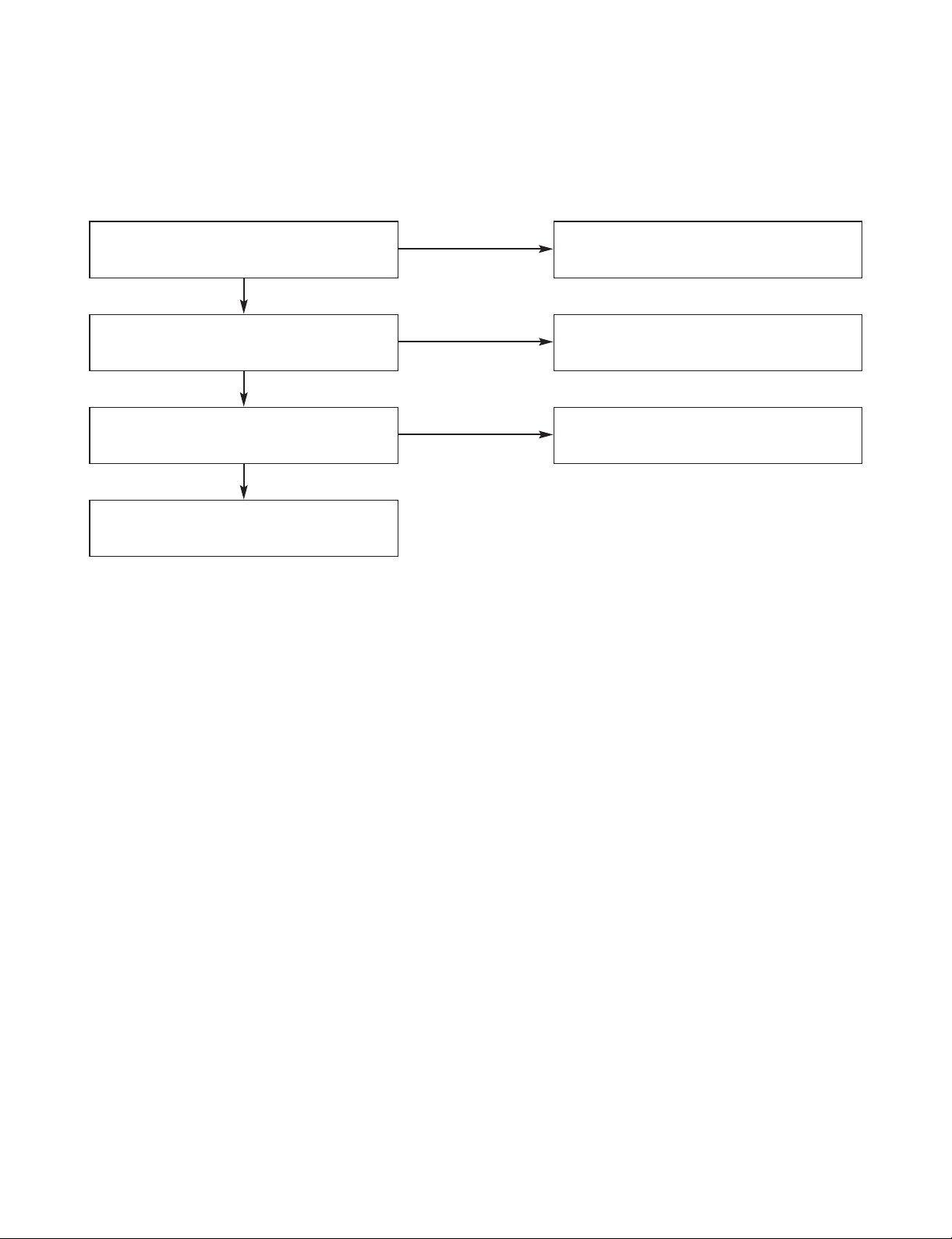
(A) Power check
2.5V is supplied to L101?
YES
NO
3.3V is supplied to IC104(37), IC105(37),
IC102(1), IC103(1), and IC201(3)?
YES
3.3V is supplied to IC106(14)?
(B) Clock check
25MHz clock is output from X101(3)?
Fig.01
YES
YES
37.5MHz clock is input to IC201(87)?
Fig.02
3.6864MHz clock is output from X102(3)?
Fig.03
YES
YES
NO
Power Supply Check
IC950(2) : 3.3V
Power Supply Check
IC954(3) : 2.5V
Power Supply Check
IC950(2) : 3.3V
Check X101
Check IC101 & IC201
Check X102
NO
NO
NO
NO
Page 15

3-6
Fig.01 X101(3) : 25MHz CPU Clock
Fig.03 X102(3) : 3.6864MHz UART Clock
Fig.02 IC201(87) : 37.5MHz PERI Clock
Page 16
3-7
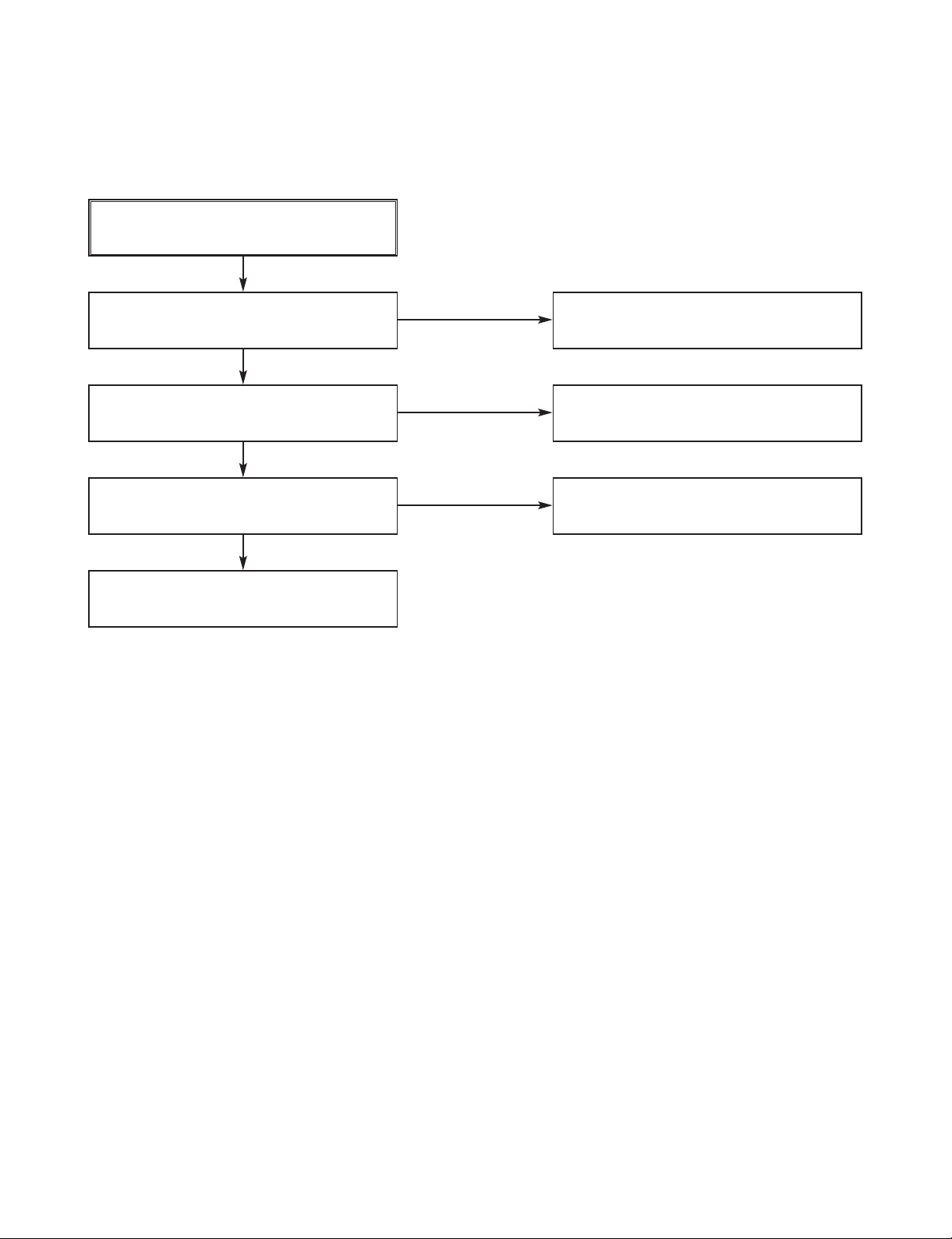
(C) Reset check
IC107(3) is reset?
YES
NO
IC106(4) is reset?
Fig.04
YES
IC201(29, 56, 61, 64, 75) are reset?
YES
NO
Check IC106
Check IC107
Check IC101 & 201
NO
Fig.04 IC106(4) : Reset signal
Page 17
3-8
(D) CS check
Logic low pulse is seen at R138?
Fig.05
YES
NO
Logic low pulse is seen at R140?
YES
Logic low pulse is seen at R144?
YES
NO
Check IC101, IC211
Check IC101, 104, 105
Check IC101, IC400
NO
Logic low pulse is seen at R143?
YES
Check IC101, IC201
NO
Fig.05 R138(1) : Flash CS signal
Page 18

3-9
(E) IIC check
IIC SDA and SCL signals are output
from IC211(19 & 18)?
Fig.06 & Fig.07
YES
NO
IIC SCL and SDA signals are output
from IC101(W17 & U15)?
YES
NO
Check IC101
Check IC211
Fig.06 IC211(19) :
3.3V IIC SDA signal
Fig.07 IC211(18) :
3.3V IIC SCL signal
Page 19
3-10
(F) Interrupt check
Logic high is input to IC101(D18) or R418?
YES
NO
Logic high is input to IC101(W20) or
CN201(7)?
YES
NO
Check IC100, CN201(7)
Check IC100, IC400
Fig.08 IC101(D18) :
No Interrupt signal
Page 20
3-11
(G) RS-232C check
RS-232C port setup is OK?
(Baudrate, Parity, Data Bit, Stop Bit)
YES
NO
IC204(10) is OK?(TxD signal)
Fig.09
YES
NO
Check IC101, IC204
IC204(9) is OK?(RxD signal)
Fig.10
YES
NO
Check IC101, IC204
Modify RS-232C port setup
Fig.09 IC204(10) : TxD signal
Fig.10 IC204(9) : RxD signal
Page 21
3-12
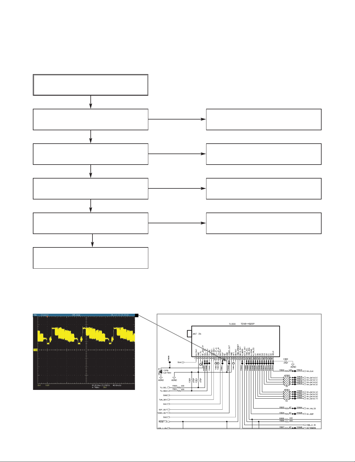
3. ATSC/QAM FRONT_END TROUBLESHOOTING
Start
Power is supplied normally(TU300)?
YES
NO
RF signal is detected?
(using Spectrum Analyzer)
YES
Check error signal(TU300(22)). (using
Oscilloscope) High:normal, Low:Error
Check NIM Tuner(TU300)’s output
signals of DATA(Fig.01)
(pin 28,29,30,31,32,33,34,35),
packet clock(
Fig.02)(pin 27) and
Byte clock(pin 36)(Fig.03).
END
YES
YES
YES
NO
Check antenna connection.
Check the power lines(A9V, D5V_2,
D3.3V_2, P_30V_TU) referring the circuit
diagram.
Check the Voltage between L303 and
Ground.
5V : normal, 0~4V : change Q300.
Check the status of connection on PCB.
Change TU300.
NO
NO
Page 22

3-13
FIG.03
TU300(36) VSB/QAM
DATA Byte Clock
FIG.02
TU300(27) VSB/QAM
DATA Packet Clock
FIG.01
TU300(28,29,30,31,32,33,34,35)
VSB/QAM DATA Outputs
Page 23
3-14
4. NTSC/FRONT_END TROUBLESHOOTING
Start
Power is supplied normally?
YES
NO
RF signal is detected?
(using Spectrum Analyzer)
YES
What Voltage is between L303 and ground ?
5V : NO 1V( below) : YES
Check NIM Tuner(TU300)’s output signal
of VIDEO_OUT(pin 16, Fig.04).
END
YES
YES
YES
NO
Check antenna connection.
Check the power lines(A9V, D5V_2,
D3.3V_2, P_30V_TU)
referring the circuit diagram
Change Q300.
Change TU300.
NO
NO
FIG.04
TU300(16) NTSC VIDEO OUT
Page 24
3-15
5. FPGA TROUBLESHOOTING
(1). NO ATSC AUDIO & VIDEO
1) Check IC801, IC960 and surroundings
3.3V is supplied to IC801?(Check C802)
NO
1.5V is supplied to IC801?(Check C812)
YES
27MHz is output from X801?
Check the ATSC/QAM tuner part
YES
YES
NO
Check IC960 and surroundings.
Check the Power Supply Part.
Check X801
NO
Page 25

3-16
6. VIDEO TROUBLESHOOTING
Start
No HV sync OUT?
NO
YES
Any problem in main picture?
NO
Any problem in AV out?
END
NO
NO
YES
What is the main picture source?
DTV or NTSC or RGB
(A)
(C1)
(D)
YES
DTV
(C2)
NTSC
(C2)
RGB
Page 26

3-17
(A)
Power is supplied to IC400[HD2]?
YES
NO
Video display clock(IC615(7)) is supplied
to HD2?
FIG.01
YES
END
YES
NO
Check X600
if there is sinusoidal 27MHz clock.
FIG.02
Check L400(1.8V), L401(3.3V) IC950(2)
(3.3V).
FIG.01
VDP clock
FIG.02
Crystal 27MHz clock
Page 27

3-20
(C2) When NTSC is main
Check tuner output composite signal
(C615)
FIG.05
YES
NG
Check NTSC decoder.
OK
Is there any quantize noise ?
END
YES
YES
NG
power check: L602 5V
Analog input: IC606 (44)
Reference clock oscillation : X601
FIG.06
Pixel clock: 13.5MHz continuous
Clock in IC606 (28).
FIG.07
Hsync out: 15.7KHz negative
pulse in IC606 (36). FIG.08
Vsync out: 59.94Hz negative
pulse in IC606 (35). FIG.09 top
Field ID : 29.97Hz pulse in
IC606 (34). FIG.09 bottom
IIC: IC606 (10(SCL), 11(SDA))
Check tuner block(TU300)
Check digital output pin short
in IC606 pin 12~19, 23~26, 30~33.
YES
FIG.05
CVBS signal from TU300
Page 28

3-21
FIG.06 X601 Reference clock
FIG.07 NTSC Decoder Pixel Clock
FIG.08 NTSC Decoder Hsync output FIG.09 NTSC Decoder Vsync out-
put(top), Field ID(bottom)
Page 29

3-22
(C2) When RGB is main
Check RGB cable is connected
YES
Check PC resolution
YES
NG
Check H:CN203(2)(Fig.10 top).
V : CN203(1) (FIG.10 middle), R:CN203(9),
G:CN203(5) ,B:CN204(4) (FIG,10 bottom)
YES
Check input selection is low : IC506(1)
YES
Check ADC output CLK: IC504(67),
H:IC504(66),V:IC504(64) : (FIG,11~13)
Digital data: IC504 pin 2~9,12~19,70~77 : (FIG.14)
YES
Is there any quantize noise ?
YES
End
NO
NG
Change resolution to 1024 x 768
NG
Check cable or video card
NG
If the pin is high, check IC201(23)
If IC203(23) is high then try power off/on.
NG
Change IC504 component
YES
Check IC400
Connect RGB cable
Page 30

3-23
FIG.10 H,V and R,G,B signal FIG.12 ADC output
h_sync(IC504(6600
FIG.11 ADC output clock(IC504(67))
FIG.14 ADC output digital data
FIG.13 ADC output
v_sync(IC504(64))
Page 31
3-24
(D)
Check NTSC mute signal is low.
NG
Check HD-II NTSC encoder part.
OK
Check NTSC analog output buffer part
OK
End
NO
NO
Check NTSC encoder pixel clock:
IC605(13)
FIG.15
NO
Check power:IC604(8); +5V IC604(4) ; –5V
Check composite:
FIG.16 top, Input:
IC604(3,5) Output: IC604(1,7)
Check Q501 base voltage.
Must be low.
If not, check IC201 pin 47
Page 32

3-25
FIG.15
27MHz NTSC encoder pixel clock
FIG.16
Composite Output(top)
Page 33

3-29
7. AUDIO TROUBLESHOOTING
(1) NO ATSC AUDIO
1) CHECK IC400 AND SURROUNDINGS
Is FPGA Part OK?
1.8V & 3.3V are supplied to IC400?
YES
NO
NO
NO
NO
NO
Data is input from TU300 to IC400(A11,
E19, A20)?
Data is output from R424? Fig.01
3.072MHz clock is output from FB401?
Fig.02
48kHz clock is output from R421?
Fig.03
YES
YES
YES
YES
NO
Check the Power Supply Part.
Check Tuner Part.
Check the surroundings of IC401.
Check the surroundings of IC401.
Check the surroundings of IC401.
Go to FPGA Troubleshooting Flow(1)
Page 34

3-30
Fig.01
Data output from R424
Fig.02
3.072MHz clock from FB401
Fig.03
48KHz clock from R421
Page 35

3-31
5V is supplied to IC701(10, 16, 49, 63)?
8V is supplied to IC701(31)?
18.432MHz Clock is input to IC701(54,
55)?
Data pulse is input to IC701(6)?
48kHz clock is input to IC701(4)?
YES
NO
NO
NO
NO
YES
YES
YES
Analog audio is output from IC701
(28, 29)? Fig.04
YES
12V is supplied to IC703(1)?
NO
Check Power Supply Part
NO
Check Power Supply Part
NO
Check X701
Check IC400
Check IC702 and surroundings
5. NO ATSC AUDIO
2) CHECK MSP4448G AND SURROUNDINGS
Fig.04
Analog audio output
Page 36

3-32
6. AUDIO TROUBLESHOOTING
3) Check IC702 and Surroundings
9V is supplied to IC702(8)?
Analog audio signal is output from
IC702(1, 7)?
YES
NO
Check IC702 and surroundings
NO
Check Power Supply Part
6. AUDIO TROUBLESHOOTING
4) Check Output Jack and Surroundings
Check Q702, Q703, Q704, Q705,
JA600 and their surroundings
Page 37

3-33
6. AUDIO TROUBLESHOOTING
(2) No NTSC Audio
ATSC Audio is OK?
SIF signal is input to the Base of Q302?
YES
NO
SIF signal is input to IC701(50)?
Fig.05
YES
Analog audio signal is output from
IC701(17, 18)?
YES
NO
NO
Check Q302
Check IC701 and surroundings.
Check TU300
NO
Go back to symptom #1
Fig.05
Analog audio output from
IC701(17, 18)
Page 38

3-34
Fig.06
SPDIF output
Fig.06
SPDIF output
6. AUDIO TROUBLESHOOTING
(3) No SPDIF Out for ATSC
ATSC Audio is OK?
SPDIF pulse is output from R423? Fig.06
SPDIF pulse is output from IC704(4)?
5V is supplied to JA701(2)?
Check JA701 and surroundings.
YES
YES
YES
YES
NO
NO
NO
Check IC400 and surroundings.
Check IC704 and surroundings.
Check Power Supply Part.
NO
Go back to symptom #1
Page 39

3-35
6. AUDIO TROUBLESHOOTING
(4) No SPDIF Out for ATSC
ATSC Audio is OK?
ATSC SPDIF is OK?
NTSC Audio is OK?
Analog audio is output from IC701
(25, 26)?
18.432MHz clock is output from
IC701(57)?
Fig.07
Data pulse is output from IC701(5)?
YES
YES
YES
YES
YES
NO
NO
NO
NO
NO
Go back to symptom #3
Go back to symptom #2
Check IC701.
Check IC701.
Check IC701.
NO
Go back to symptom #1
Fig.07
18.432MHz clock output from
IC701(57)
Page 40

3-36
Video is OK?
Audio is output form pin 6 and 8 of CN203
11 pin is connection Cable OK?
Junction Board(6870R3815HA) is OK?
External A/V Test Card(IP card) is OK?
YES
YES
YES
YES
External A/V Test Cable is OK?
YES
Check IC701(35, 36)
YES
NO
NO
NO
Check CN203 and surrounding
Check 11 pin Connection Cable
Check Junction Board(6870R3815HA)
NO
Check External A/V Test Card
NO
Check Testing Cable
NO
Check Testing Cable
NO
Check External Video Input
YES
YES
YES
YES
YES
6. AUDIO TROUBLESHOOTING
(5) No External Audio
Page 41

3-37
External Audio is OK?
ATSC SPDIF is OK?
Analog audio is input to IC701(35, 36)?
18.432MHz clock is output from
IC701(57)? Fig.07
Data pulse is output from IC701(5)?
YES
YES
YES
YES
NO
NO
NO
Go back to symptom #3
Go back to symptom #6
Check IC701.
NO
Check IC701.
NO
Go back to symptom $5
YES
YES
YES
6. AUDIO TROUBLESHOOTING
(6) No SPDIF for External Audio
Page 42

3-38
1. OVERALL BLOCK DIAGRAM
BLOCK DIAGRAM
11
10
9
8
7
6
5
4
3
2
1
8
7
6
5
4
3
2
1
MAIN Board
5
4
3
2
1
DISPLAY_RXD
DISPLAY_TXD
GND
1 NC
2 GND
3 RGB_R
4 AUD_R
5 GND
6 AUD_L
7 RGB_G
8 RGB_B
9 GND
10 H Sync
11 V Sync
8 F_RESET
7 /FC_IRQ
6 FC_DATA
5 CF_DATA
4 CF_CLK
3 CF_STB
2 5V
1 GND
6 AUX_CTRL 6
5
4
3
2 PTC_RXD
1 PTC_TXD
Board
MPI/SPI
123456789
9 MPI_DIN
8 MPI_DOUT
7 SPI_DOUT
6 SPI_DIN
5 SPI_CLK
11 12V
10 GND
4 GND
10
3 5V
2 IR_DOUT
11
1 NC
AC120V
123456789
1 4V
2 4V
3 3V
4 GND
5 GND
6 6.5V
7 GND
8 12V
SMPS
101112
9 GND
10 30V
11 GND
12 -8V
Board
5
4
3
2
1
PROTOCOL Board
5 5V
4 GND
3 GND
2 12V
1 12V
Page 43

3-39
2. POWER BLOCK DIAGRAM
5VA
12VA
P102
RECTIFIER &
RECTIFIER &
SMOOTING BLOCK
RECTIFIER &
SMOOTING BLOCK
SMOOTING BLOCK
12VA
RECTIFIER &
P102
REG
BLOCK
K
SMOOTING BLOC
3.2VA
3.8VA
SMOOTING
RECTIFIER &
12VA
5.5VA
5.V
BLOCK
30VA
K
REG
BLOC
BLOCK
FEED-BACD
R124,R125,
-8VA
R126,R123.
R121.C120
122
R
18
TRANS
2
BLOCK
SNUBBER
+
R101
NOISE FILTER
17
16
(D101,C105
C106,R103)
DIODE
BRIDGE
BLOCK
(C101,L102,
14
15
4
DRIVE & S/W BLOCK
(BD101)
L101, C102)
13
12
10,11
8
6
C108, C112,C113,
SOFT-START BLOCK
R106, R109, R108,D105 )
(IC101,BD01, D102, R105,
(IC102)
PHOTO COUPER
AMP
ERROR
Y-CAP
C111
Y-CAP
C110
(IC103)
FUSE
(F101 )
BR BL
(BK)(WH)
NOTES) Warning
NOTES) Parts that are shaded are critical
NOTES) With respect to risk of fire or
NOTES) electricial shock.
Page 44

3-40
3. BLOCK DIAGRAM
Optical Out
Digital Audi o
l
IC702
Contr o
SPDIF MUTE
MUX
(74LCX157)
o
Digital A udi
IC704
Buffer
Audio Ou t 1&2
(MC33078)
Processor
MTS / SAP
(MSP4448G)
IC701
2CH L/R Audi o Out
Audio In 1
RGB Video In
IP Card (MPI 2)
IC606
RGB MUTE
X601
X-tal
20.25 MHz
Clock Gen.
X-tal
X701
18.432 MHz
NTSC Audio
I2C CH1
Video Out 1,2
X-tal
X600
27 MHz
AMP
(TK15420)
IC604
R,C
LPF
VCR out (Comp. )
Main PWM
08A)
Clock Gen.
(CY244 ZXC
NT2CLK
SYSCLK
Main VDP Clock
IC615
IC500
DVI Clock
TMDS CH0,1,2
DVI Out
TMDS CLK +-
DVI
Transmitter
w/ HDCP
I2C CH1
(Sil170)
I2C Ext.
(82B715)
IC501
I2C CH2
Digital RGB, Hs, Vs,DE
2CH Monitor Audi o
ADC
VPX3226E
YC
VIDEO PIXEL DECODER
Filter
4H Comb
YCbCr
Digital
Decoder
RGB
IC400
TP Demux /
Video Decoder /
Audio Decoder /
(LGDT1102 : HD-II)
Format Converter /
Video Display Processo r
AC120V
IC608
Sync Sep.
(EL1881M)
NTSC Video
I2C CH1
Vsync
I2C CH1
IF
ATSC
Down
SAW 2
Conver ter
W 1
ATSC
SA
VIF
Mix &
OSC & PLL
Video ADC
(AD9883)
External RGB Input
IC504
TDVB-H920P
AMP
BPF &
AT/NT NIM TUNER
RF IN
AIR/CABLE
TU300
ATSC TP
Digital A udi o Out
2CH L/R Audi o Out
FPGA
/ByPass
Decryption
(EP1C12F256)
IC801
ROM
IC802
IC404~405
Outputs
EPLD
(EPM3064A)
SDRAM
(2Mx32bx2)
Inputs
-Reset Gen.
-Ready Gen.
-Output Exp.
-HD-II DMA I/F
IC957
1.8V-2
-Video Gl ue.
ATSC TP
I2C CH2
IC212
I2C
CON-
TROLLER
(PCA9564)
I2C
CON-
TROLLER
(PCA9564)
IC211
I2C CH0
(32Kx8b)
EEPROM
IC203 IC201SW201
CPU I/F
(1Mx16x2)
Flash ROM
IC104~105
X102
Memory I/F
SDRAM
(4Mx16bx2)
IC102~103
I2C CH1
VSB/QAM
Channel
Swit ch
SW Contro l
Decoder
(LGDT3302)
IC301
(74HC4066)
I2C CH1
Display TYPE
OSC
IC101
CPU CLK
CPU
(PPC405CR)
UART1
Driver
RS232
(MAX232)
X101
RGB/YPbPr
I2C CH1
25MHz
SMPS
.8
3V
4V
12V
-8V
30V
6.5V
SC1565IST-1
3.6864MHz
IC204
78R33F
3.3V-2
KIA
3.3V-1
KIA378R33PI
IC950
OSC
UART CLK
2.5V-1
SC1565IST-2.5
.8
1.8V-1
SC1565IST-1
IC955
UART0
Sys Reset
(KIA7029 &
5V-2
5V-1
IC952
14)
74HC
78R05F
KIA
78R05F
KIA
IC107 & 106
A9V/A9 V-A
Audio 8 V
IC703
IR
x 2
KIA78R09F
08F
KIA78DL
3.3V-ADC
er
Receiv
-5V
IC961
PTC
KIA79L05F
KIA78R33F
IC951
IC954
IC958
IC953
IC956/959
1.5V
SC15651S
IC960
BOARD
DEBUG PORT
AUX CONTROL
Page 45

Page 46

3-45 3-46
3. CPU PERI & IR-IN & AUX-CTRL CIRCUIT DIAGRAM
A B C D E F G H I J K L M N O P Q R ST
Page 47

3-47 3-48
4. TERRESTRIAL FRONT_END CIRCUIT DIAGRAM
A B C D E F G H I J K L M N O P Q R ST
Page 48

3-49 3-50
5. HD2 & SDRAM CIRCUIT DIAGRAM
Page 49

3-51 3-52
6. DVI TRANSMITTER CIRCUIT DIAGRAM
A B C D E F G H I J K L M N O P Q R ST
Page 50

3-53 3-54
7. VDP I/F & DISPLAY OUTPUT CIRCUIT DIAGRAM
A B C D E F G H I J K L M N O P Q R ST
Page 51

8. NTSC AUDIO PROCESSOR CIRCUIT DIAGRAM
A B C D E F G H I J K L M N O P Q R ST
3-55 3-56
Page 52

3-57 3-58
9. POWER REGULATION CIRCUIT DIAGRAM
A B C D E F G H I J K L M N O P Q R ST
Page 53

10. FPGA FOR DECRYOPTION CIRCUIT DIAGRAM
A B C D E F G H I J K L M N O P Q R ST
3-59 3-60
Page 54

3-61 3-62
PRINTED CIRCUIT DIAGRAMS
1. DIGITAL MAIN PRINTED CIRCUIT DIAGRAMS(TOP)
Page 55

3-63 3-64
2. DIGITAL MAIN PRINTED CIRCUIT DIAGRAMS(BOTTOM)
Page 56

3-65 3-66
3. MPI PRINTED CIRCUIT DIAGRAM
(TOP VIEW) (BOTTOM VIEW)
Page 57

3-67 3-68
4. PTC PRINTED CIRCUIT DIAGRAM
(TOP VIEW) (BOTTOM VIEW)
Page 58

3-69 3-70
5. BACK PLANE PRINTED CIRCUIT DIAGRAM
(TOP VIEW)
(BOTTOM VIEW)
6. POWER PRINTED CIRCUIT DIAGRAM
LOCATION GUIDE
NOTES) Warning
NOTES) Parts that are shaded are critical
NOTES) With respect to risk of fire or
NOTES) electricial shock.
Page 59

Page 60

NOTES)
)
If you want to purchase
Flash memory, you must order
" IC104A.IC105A "
NOTES)
Warning
Parts that are shaded are critical With
respect to risk of fire or electrical
shock.
SECTION REPLACEMENT PARTS LIST
MODEL :4LST-5600A(LGEUS
RUN DATE : 11-JULY-05
SALLOCA. NO. PART NO. DESCRIPTION SPECIFICATION REMARKS
*** INDIVIDUAL PARTS ***
250 3110R-V030B CASE TOP(LST-4600A) PRESS W/O LOGO
264 1BK-0512391 BOLT,HEXAGON SOCKET HEAD D5.1 L7.0 STS 430
266 4810R-0252A BRACKET SETTOP BOX WALL(LST-4600A) PRE
300 6410RADK10A POWER CORD KJP-120/KJC-303 3PIN KUKJE UL/
465 1SZZR-0097K SCREW,DRAWING + 2 D3.0 L10.0 MSWR3/FZB 3 CR
465 1SZZR-0097K SCREW,DRAWING + 2 D3.0 L10.0 MSWR3/FZB 3 CR
467 1SZZR-0098G SCREW,DRAWING + 2 D3.0 L8.0 MSWR3/FZMCW-1 3C
471 1SZZR-0098H SCREW,DRAWING + 2 D3.0 L8.0 MSWR3/FZMCW-1 3
472 1SZZR-0098K SCREW,DRAWING + 2 D3.0 21MM MSWR3/FZMCY-1 3C
801 3835RB0002K INSTRUCTION ASSEMBLY SETTOP BOX LST-5600A-AA1ULL 3R
802 3890R-C120V BOX LST-5600A AA1ULL SWW3-A STB
803 3920R-E109A PACKING SETTOP BOX LST-4600A 80 STB
804 3858R-S001A SHEET (MECH) Packing LDPE 600M 630MM 0.5 VC NSP
822 6850R-TIA81 CABLE,D-SUB RS232 9P MALE-FEMALE HYOSUNG 1
823 6850R-ZAC06 CABLE,COAXIAL DVI-D(KCA-SI-0-0015) KSD 1.8M
826 6200RJB002B FILTER(CIRC),DRAWING ZCAT2035-0930 TDK
827 6850R-NAA81 CABLE,COAXIAL 1P AUDIO PLUG TO 2P RCA CABLE(
900 6712000003A REMOTE CONTROLLER RECEIVER OHSUNG ASSY OHSUNG .HZ LSC 460
*** CHASSIS ASSEMBLY ***
A44 3141R-B001J CHASSIS ASSEMBLY LST-5600A MAIN CHASSIS ASSY
261 5040R-0069S RUBBER CCD 05 NEW SILICON OTHER 2T (3
262 6620K00006A SOCKET(CIRC),POWER KJA-ET-0-0007 AC UL/CSA 3PPIN
263 6631R-Y014A CONNECTOR ASSEMBLY KHC-ET-0-0015 KSD AC INLET 6P
320 3720R-D131A PANEL,VIDEO SETTOP BOX LST-5600A PRESS
330 3140R-V011C CHASSIS LST-5600A PRESS
468 1SZZR-0097N SCREW,DRAWING + 2 D3.0 L8.0 MSWR3/FZB 3CR BK
469 1SZZR-0076A SCREW,DRAWING + 2 D4.0 L8.0 SWCH18A/NI
*** BOARD ASSEMBLY ***
A47 3501R-2259A BOARD ASSEMBLY SETTOP BOX LST-3600 EVENT_PPV_
IC101 0IPMGSK002A IC,POWER MANAGEMENT STR-G6352T SANKEN 5PIN TO220 S
D121 4811R-0043A BRACKET ASSEMBLY FMB-G24H_HEAT SINK
D127 0DRSA00020A DIODE,RECTIFIERS FMB-G24H LF651 SANKEN BK NON
D127 0DR104510AB DIODE,RECTIFIERS B10A45V1 NO CUT KEC ST TO220 4 ALTERNATE
D129 0DRSA00020A DIODE,RECTIFIERS FMB-G24H LF651 SANKEN BK NON
D129 0DR104510AB DIODE,RECTIFIERS B10A45V1 NO CUT KEC ST TO220 4 ALTERNATE
BD01 636-004C FILTER(CIRC),EMC BEAD CORE BFS3550R2FD8,R T/P
BD101 0DD160000DA DIODE,RECTIFIERS S1WBA60 BK SHINDENGEN - 600V -
C101 624-088F CAPACITOR,DRAWING PCX2 275V 0.1UF,M (PILKO)
C102 624-088F CAPACITOR,DRAWING PCX2 275V 0.1UF,M (PILKO)
C103 0CE227JR6A0 CAPACITOR,FIXED ELECTROLYTIC 220UF SMH,HC 250V 20% BULK VNS
C105 0CQ1031Y519 CAPACITOR,FIXED FILM 0.01UF D 630V 10% PE NI TP5
C106 624-087B CAPACITOR,FIXED CERAMIC(HIGH D HIGH-VOL 100P/1KV SMPS SAMHWA
C108 0CE1064K638 CAPACITOR,FIXED ELECTROLYTIC 10UF SRA,SS 50V 20% FM5 TP 5
C109 0CQ4731N409 CAPACITOR,FIXED FILM 0.047UF D 100V 5% PE TP5
C110 0CG1020U630 CAPACITOR,FIXED CERAMIC(TEMP.C 1000PF D 400V 20% E(Z5U) R
C111 0CG2220U630 CAPACITOR,FIXED CERAMIC(TEMP.C 2200PF D 400V 20% E(Z5U) R
C112 0CN223AK948 CAPACITOR,TUBULAR(HIGH DIELEC) 0.022UF 50V Z F TA26 S
1-4
Page 61

SALLOCA. NO. PART NO. DESCRIPTION SPECIFICATION REMARKS
C113 0CN4710K518 CAPACITOR TUBULA(HIGH DIELE) 470P 50V K B TA26
C120 0CE1054K638 CAPACITOR,FIXED ELECTROLYTIC 1UF SRA,SS 50V 20% FM5 TP 5
C122 0CE2282F611 CAPACITOR,FIXED ELECTROLYTIC 2200UF KMF 16V 20% BK7.5 FL
C123 624-082H CAPACITOR,FIXED ELECTROLYTIC CE 1000UF/10V SHL(10*12.5)T/P
C124 0CE2282F611 CAPACITOR,FIXED ELECTROLYTIC 2200UF KMF 16V 20% BK7.5 FL
C125 624-082H CAPACITOR,FIXED ELECTROLYTIC CE 1000UF/10V SHL(10*12.5)T/P
C127 624-085D CAPACITOR,FIXED ELECTROLYTIC CE 47UF/50V KME (SMPS)
C128 624-085D CAPACITOR,FIXED ELECTROLYTIC CE 47UF/50V KME (SMPS)
C129 624-085D CAPACITOR,FIXED ELECTROLYTIC CE 47UF/50V KME (SMPS)
C134 0CE108EH610 CAPACITOR,FIXED ELECTROLYTIC 1000UF KMG 25V 20% BULK FL
C152 624-085D CAPACITOR,FIXED ELECTROLYTIC CE 47UF/50V KME (SMPS)
C154 0CE1074F638 CAPACITOR,FIXED ELECTROLYTIC 100UF SRA,SS 16V 20% FM5 TP 5
D101 0DD010009CA DIODE,RECTIFIERS EG01C TP SANKEN - - - - - -
D101 0DD221009AA DIODE,RECTIFIERS ERA22-10 KFLB,TP ,R T/P,FUJI ALTERNATE
D102 0DR104009BA DIODE,RECTIFIERS RL104F TP RECTRON - 400V 1A 30
D105 0DD133009AA DIODE,SWITCHING 1SS133 TP ROHM KOREA - - - - -
D124 0DR104510AA DIODE,RECTIFIERS B10A45V1 BK KEC TO220 45V 10A
D125 0DR104009BA DIODE,RECTIFIERS RL104F TP RECTRON - 400V 1A 30
D126 0DR104009BA DIODE,RECTIFIERS RL104F TP RECTRON - 400V 1A 30
D129 0DRFC00091A DIODE,RECTIFIERS FFPF06U40STU FAIR CHILD ST TO2
D152 0DR104510AA DIODE,RECTIFIERS B10A45V1 BK KEC TO220 45V 10A
D153 0DR104510AA DIODE,RECTIFIERS B10A45V1 BK KEC TO220 45V 10A
F101 0FS1601B51B FUSE,SLOW BLOW 1600MA 250 V 5.2X20 CY/GL KS /
FH01 586-008B HOLDER FUSE CLIP TP SINSUNG
FH02 586-008B HOLDER FUSE CLIP TP SINSUNG
IC102 657-063A SENSOR LTV-817B,PHOTO COUPLER(LITEON)
IC103 0ISS431000A IC,SAMSUNG ELECTRONICS KA431AZ (LM431AZ) - - - -
IC103 0IKE431000A IC,KEC KIA431 3 PIN TP - - ALTERNATE
IC151 0IPMGSH010A IC,POWER MANAGEMENT PQ12RD1L SHARP 4PIN TO-220 ST
IC151 0IKE781200S IC,KEC KIA78R12PI CU 4P TO-220IS ST 1 ALTERNATE
IC151 0IPMGFA017A IC,POWER MANAGEMENT KA78R12TSTU FAIRCHILD 4P TO-22 ALTERNATE
IC153 0IPMGFA032A IC,POWER MANAGEMENT KA78R05TSTU FAIRCHILD 4P TO-22
IC153 0IPMGKE018A IC,POWER MANAGEMENT KIA78R05API CU KEC 4P TO-220IS ALTERNATE
L101 6200RLB007C FILTER(CIRC),EMC LFOR SERIES(TOROIDAL COIL) SAM
L102 616-145H FILTER(CIRC),DRAWING SHT LFS2020V4-04350
L121 6140RCC009A COIL,RF BAR CHOKE COIL 2 PIN 10 UHCCAR
L122 633-088D COIL,CHOKE 20UH KWANGSUNG LEAD CUT
L123 633-088G COIL,CHOKE 22MH TOKO 5MM TP
P101 561-715L CONNECTOR (CIRC),WAFER GIL-G-12P-S3T2-E LG CABLE 12PI
P102 6631R-F010U CONNECTOR ASSEMBLY GIL-G-5P/GIL-J-5S 5P 80M/M L
PW101 6630VM01502 CONNECTOR (CIRC),WAFER JE202-1-T-02(3-2)W JAE EUN 2P
R100 0RD1504H632 RESISTOR,FIXED CARBON FILM 1.5M OHM 1/2 W 5.00% MF10
R101 0RD1803F608 RESISTOR,FIXED CARBON FILM 180K OHM 1/6 W 0.05 TA26
R102 0RD1803F608 RESISTOR,FIXED CARBON FILM 180K OHM 1/6 W 0.05 TA26
R103 0RS5602K619 RESISTOR,FIXED METAL OXIDE FIL 56K OHM 2 W 5.00% TR
R105 0RD0102F608 RESISTOR,FIXED CARBON FILM 10 OHM 1/6 W 5% TA26
R106 0RD6800F608 RESISTOR,FIXED CARBON FILM 680 OHM 1/6 W 5% TA26
R107 614-007A RESISTOR,FIXED CEMENT 2.7/2W CEMENT SMPS V
R108 0RD4701F608 RESISTOR,FIXED CARBON FILM 4.7K OHM 1/6 W 5% TA26
R109 0RS0350K619 RESISTOR,FIXED METAL OXIDE FIL 0.35 OHM 2 W 5.00% TR
R121 0RD1800F608 RESISTOR,FIXED CARBON FILM 180 OHM 1/6 W 5% TA26
R122 0RD2201F608 RESISTOR,FIXED CARBON FILM 2.2K OHM 1/6 W 5% TA26
R123 0RD1001F608 RESISTOR,FIXED CARBON FILM 1K OHM 1/6 W 5% TA26
R124 0RN1801F408 RESISTOR,FIXED METAL FILM 1.8K OHM 1/6 W 1% TA26
R125 0RN3301F408 RESISTOR,FIXED METAL FILM 3.3K OHM 1/6 W 1% TA26
R126 0RD1200F608 RESISTOR,FIXED CARBON FILM 120 OHM 1/6 W 5% TA26
R128 0RD1003F608 RESISTOR,FIXED CARBON FILM 100K OHM 1/6 W 5% TA26
2-4
Page 62

SALLOCA. NO. PART NO. DESCRIPTION SPECIFICATION REMARKS
R129 0RF0300F708 RESISTOR,VARIABLE[CARBON FILM] 0.3 OHM 1/6 W 10% TA26
R156 0RD3901F608 RESISTOR,FIXED CARBON FILM 3.9K OHM 1/6 W 5% TA26
R157 0RD3901F608 RESISTOR,FIXED CARBON FILM 3.9K OHM 1/6 W 5% TA26
R161 0RD2200F608 RESISTOR,FIXED CARBON FILM 220 OHM 1/6 W 5% TA26
R162 0RD2200F608 RESISTOR,FIXED CARBON FILM 220 OHM 1/6 W 5% TA26
R163 0RD2200F608 RESISTOR,FIXED CARBON FILM 220 OHM 1/6 W 5% TA26
T101 6170RNGW15J TRANSFORMER,SMPS[COIL] EER3530 590UH SOOJUNG PPV STB
V101 656-004C VARISTOR,DRAWING SVC681D-10A SAMHWA 4.O CUT
ZD152 0DZ332609BA DIODE,ZENERS UZ-33BSB 26MM TP PYUNG CHANG D
*** PWB(PCB) ASSEMBLY,TOTAL ***
A46 6871R-3955A PWB(PCB) ASSEMBLY,TOTAL LST-5600A MAIN PCB TOTAL
AR111 0RRZVTA001M RESISTOR,DRAWING 4.7K OHM 1 / 10 W 1608 4P 5% R
AR111 0RRZVTA001J RESISTOR,DRAWING 4.7K OHM 1 / 16 W 3216 5% R/TP ALTERNATE
AR112 0RRZVTA001M RESISTOR,DRAWING 4.7K OHM 1 / 10 W 1608 4P 5% R
AR112 0RRZVTA001J RESISTOR,DRAWING 4.7K OHM 1 / 16 W 3216 5% R/TP ALTERNATE
AR113 0RRZVTA001M RESISTOR,DRAWING 4.7K OHM 1 / 10 W 1608 4P 5% R
AR113 0RRZVTA001J RESISTOR,DRAWING 4.7K OHM 1 / 16 W 3216 5% R/TP ALTERNATE
AR114 0RRZVTA001M RESISTOR,DRAWING 4.7K OHM 1 / 10 W 1608 4P 5% R
AR114 0RRZVTA001J RESISTOR,DRAWING 4.7K OHM 1 / 16 W 3216 5% R/TP ALTERNATE
AR117 0RRZVTA001M RESISTOR,DRAWING 4.7K OHM 1 / 10 W 1608 4P 5% R
AR117 0RRZVTA001J RESISTOR,DRAWING 4.7K OHM 1 / 16 W 3216 5% R/TP ALTERNATE
AR118 0RRZVTA001M RESISTOR,DRAWING 4.7K OHM 1 / 10 W 1608 4P 5% R
AR118 0RRZVTA001J RESISTOR,DRAWING 4.7K OHM 1 / 16 W 3216 5% R/TP ALTERNATE
AR135 0RRZVTA001M RESISTOR,DRAWING 4.7K OHM 1 / 10 W 1608 4P 5% R
AR135 0RRZVTA001J RESISTOR,DRAWING 4.7K OHM 1 / 16 W 3216 5% R/TP ALTERNATE
AR136 0RRZVTA001M RESISTOR,DRAWING 4.7K OHM 1 / 10 W 1608 4P 5% R
AR136 0RRZVTA001J RESISTOR,DRAWING 4.7K OHM 1 / 16 W 3216 5% R/TP ALTERNATE
AR201 0RRZVTA001M RESISTOR,DRAWING 4.7K OHM 1 / 10 W 1608 4P 5% R
AR201 0RRZVTA001J RESISTOR,DRAWING 4.7K OHM 1 / 16 W 3216 5% R/TP ALTERNATE
AR300 0RRZVTA001K RESISTOR,DRAWING 51 OHM 1 / 10 W 1608 4P 5% R/T
AR301 0RRZVTA001K RESISTOR,DRAWING 51 OHM 1 / 10 W 1608 4P 5% R/T
AR400 0RRZVTA001K RESISTOR,DRAWING 51 OHM 1 / 10 W 1608 4P 5% R/T
AR401 0RRZVTA001K RESISTOR,DRAWING 51 OHM 1 / 10 W 1608 4P 5% R/T
AR402 0RRZVTA001K RESISTOR,DRAWING 51 OHM 1 / 10 W 1608 4P 5% R/T
AR403 0RRZVTA001K RESISTOR,DRAWING 51 OHM 1 / 10 W 1608 4P 5% R/T
AR404 0RRZVTA001K RESISTOR,DRAWING 51 OHM 1 / 10 W 1608 4P 5% R/T
AR405 0RRZVTA001K RESISTOR,DRAWING 51 OHM 1 / 10 W 1608 4P 5% R/T
C118 0CH1104K512 CAPACITOR,FIXED CERAMIC(TEMP.C 0.1UF 50V 10% B(5YP) 1608 R/TP
C121 0CH1104K512 CAPACITOR,FIXED CERAMIC(TEMP.C 0.1UF 50V 10% B(5YP) 1608 R/TP
C124 0CH1104K512 CAPACITOR,FIXED CERAMIC(TEMP.C 0.1UF 50V 10% B(5YP) 1608 R/TP
C133 0CH1104K512 CAPACITOR,FIXED CERAMIC(TEMP.C 0.1UF 50V 10% B(5YP) 1608 R/TP
C135 0CH8106F611 CAPACITOR,FIXED ELECTROLYTIC 10UF 16V 20% 85STD (CYL) R/TP
C1401 0CH8106F611 CAPACITOR,FIXED ELECTROLYTIC 10UF 16V 20% 85STD (CYL) R/TP
C160 0CH1104K512 CAPACITOR,FIXED CERAMIC(TEMP.C 0.1UF 50V 10% B(5YP) 1608 R/TP
C161 0CH8476F611 CAPACITOR,FIXED ELECTROLYTIC 47UF 16V 20% 85STD (CYL) R/TP
C162 0CH8106F611 CAPACITOR,FIXED ELECTROLYTIC 10UF 16V 20% 85STD (CYL) R/TP
C163 0CH4101K412 CAPACITOR,FIXED CERAMIC(HIGH D 100PF 50V 5% NP0 1608 R/TP
C166 0CH4101K412 CAPACITOR,FIXED CERAMIC(HIGH D 100PF 50V 5% NP0 1608 R/TP
C201 0CH1104K512 CAPACITOR,FIXED CERAMIC(TEMP.C 0.1UF 50V 10% B(5YP) 1608 R/TP
C205 0CH1104K512 CAPACITOR,FIXED CERAMIC(TEMP.C 0.1UF 50V 10% B(5YP) 1608 R/TP
C210 0CH1104K512 CAPACITOR,FIXED CERAMIC(TEMP.C 0.1UF 50V 10% B(5YP) 1608 R/TP
C212 0CH1104K512 CAPACITOR,FIXED CERAMIC(TEMP.C 0.1UF 50V 10% B(5YP) 1608 R/TP
C214 0CH1104K512 CAPACITOR,FIXED CERAMIC(TEMP.C 0.1UF 50V 10% B(5YP) 1608 R/TP
C215 0CH1104K512 CAPACITOR,FIXED CERAMIC(TEMP.C 0.1UF 50V 10% B(5YP) 1608 R/TP
C217 0CH1104K512 CAPACITOR,FIXED CERAMIC(TEMP.C 0.1UF 50V 10% B(5YP) 1608 R/TP
C228 0CH1104K512 CAPACITOR,FIXED CERAMIC(TEMP.C 0.1UF 50V 10% B(5YP) 1608 R/TP
C230 0CH4331K412 CAPACITOR,FIXED CERAMIC(HIGH D 330PF 50V 5% NP0 1608 R/TP
3-4
Page 63

SALLOCA. NO. PART NO. DESCRIPTION SPECIFICATION REMARKS
C231 0CH4331K412 CAPACITOR,FIXED CERAMIC(HIGH D 330PF 50V 5% NP0 1608 R/TP
C234 0CH1104K512 CAPACITOR,FIXED CERAMIC(TEMP.C 0.1UF 50V 10% B(5YP) 1608 R/TP
C235 0CH1104K512 CAPACITOR,FIXED CERAMIC(TEMP.C 0.1UF 50V 10% B(5YP) 1608 R/TP
C236 0CH1104K512 CAPACITOR,FIXED CERAMIC(TEMP.C 0.1UF 50V 10% B(5YP) 1608 R/TP
C237 0CH1104K512 CAPACITOR,FIXED CERAMIC(TEMP.C 0.1UF 50V 10% B(5YP) 1608 R/TP
C238 0CH4331K412 CAPACITOR,FIXED CERAMIC(HIGH D 330PF 50V 5% NP0 1608 R/TP
C239 0CH4331K412 CAPACITOR,FIXED CERAMIC(HIGH D 330PF 50V 5% NP0 1608 R/TP
C240 0CH1104K512 CAPACITOR,FIXED CERAMIC(TEMP.C 0.1UF 50V 10% B(5YP) 1608 R/TP
C252 0CH1104K512 CAPACITOR,FIXED CERAMIC(TEMP.C 0.1UF 50V 10% B(5YP) 1608 R/TP
C260 0CH1102K562 CAPACITOR,FIXED CERAMIC(TEMP.C 1000PF 50V 10% X7R(X) 1608 R/T
C273 0CH4330K412 CAPACITOR,FIXED CERAMIC(HIGH D 33PF 50V 5% NP0 1608 R/TP
C274 0CH4330K412 CAPACITOR,FIXED CERAMIC(HIGH D 33PF 50V 5% NP0 1608 R/TP
C275 0CH4330K412 CAPACITOR,FIXED CERAMIC(HIGH D 33PF 50V 5% NP0 1608 R/TP
C276 0CH1102K562 CAPACITOR,FIXED CERAMIC(TEMP.C 1000PF 50V 10% X7R(X) 1608 R/T
C277 0CH8107F611 CAPACITOR,FIXED ELECTROLYTIC 100UF 16V 20% 85STD (CYL) R/TP
C278 0CH1104K512 CAPACITOR,FIXED CERAMIC(TEMP.C 0.1UF 50V 10% B(5YP) 1608 R/TP
C279 0CH1104K512 CAPACITOR,FIXED CERAMIC(TEMP.C 0.1UF 50V 10% B(5YP) 1608 R/TP
C288 0CH4330K412 CAPACITOR,FIXED CERAMIC(HIGH D 33PF 50V 5% NP0 1608 R/TP
C289 0CH4330K412 CAPACITOR,FIXED CERAMIC(HIGH D 33PF 50V 5% NP0 1608 R/TP
C291 0CH8106F611 CAPACITOR,FIXED ELECTROLYTIC 10UF 16V 20% 85STD (CYL) R/TP
C292 0CH8106F611 CAPACITOR,FIXED ELECTROLYTIC 10UF 16V 20% 85STD (CYL) R/TP
C293 0CH1222K562 CAPACITOR,FIXED CERAMIC(TEMP.C 2200PF 50V 10% X7R(X) 1608 R/T
C294 0CH1222K562 CAPACITOR,FIXED CERAMIC(TEMP.C 2200PF 50V 10% X7R(X) 1608 R/T
C306 0CH8107F611 CAPACITOR,FIXED ELECTROLYTIC 100UF 16V 20% 85STD (CYL) R/TP
C307 0CH1474K562 CAPACITOR,FIXED CERAMIC(TEMP.C 470000PF 1608 50V 10% - R/TP
C308 0CH8107F611 CAPACITOR,FIXED ELECTROLYTIC 100UF 16V 20% 85STD (CYL) R/TP
C309 0CH1474K562 CAPACITOR,FIXED CERAMIC(TEMP.C 470000PF 1608 50V 10% - R/TP
C310 0CH8107F611 CAPACITOR,FIXED ELECTROLYTIC 100UF 16V 20% 85STD (CYL) R/TP
C311 0CH1474K562 CAPACITOR,FIXED CERAMIC(TEMP.C 470000PF 1608 50V 10% - R/TP
C312 0CH8107F611 CAPACITOR,FIXED ELECTROLYTIC 100UF 16V 20% 85STD (CYL) R/TP
C314 0CH4270K412 CAPACITOR,FIXED CERAMIC(HIGH D 27PF 50V 5% NP0 1608 R/TP
C315 0CH4270K412 CAPACITOR,FIXED CERAMIC(HIGH D 27PF 50V 5% NP0 1608 R/TP
C316 0CH8476K611 CAPACITOR,FIXED ELECTROLYTIC 47UF 50V 20% 85STD (CYL) R/TP
C317 0CH1104K512 CAPACITOR,FIXED CERAMIC(TEMP.C 0.1UF 50V 10% B(5YP) 1608 R/TP
C318 0CH8107F611 CAPACITOR,FIXED ELECTROLYTIC 100UF 16V 20% 85STD (CYL) R/TP
C319 0CH1474K562 CAPACITOR,FIXED CERAMIC(TEMP.C 470000PF 1608 50V 10% - R/TP
C320 0CH8107F611 CAPACITOR,FIXED ELECTROLYTIC 100UF 16V 20% 85STD (CYL) R/TP
C321 0CH1104K512 CAPACITOR,FIXED CERAMIC(TEMP.C 0.1UF 50V 10% B(5YP) 1608 R/TP
C322 0CH1104K512 CAPACITOR,FIXED CERAMIC(TEMP.C 0.1UF 50V 10% B(5YP) 1608 R/TP
C379 0CE105VK6DC CAPACITOR,FIXED ELECTROLYTIC 1UF MV 50V 20% R/TP(SMD) SMD
C384 0CH4470K412 CAPACITOR,FIXED CERAMIC(HIGH D 47PF 50V 5% NP0 1608 R/TP
C402 0CH8226F611 CAPACITOR,FIXED ELECTROLYTIC 22UF 16V 20% 85STD (CYL) R/TP
C403 0CH1104K512 CAPACITOR,FIXED CERAMIC(TEMP.C 0.1UF 50V 10% B(5YP) 1608 R/TP
C432 0CH1104K512 CAPACITOR,FIXED CERAMIC(TEMP.C 0.1UF 50V 10% B(5YP) 1608 R/TP
C433 0CH1104K512 CAPACITOR,FIXED CERAMIC(TEMP.C 0.1UF 50V 10% B(5YP) 1608 R/TP
C439 0CH1104K512 CAPACITOR,FIXED CERAMIC(TEMP.C 0.1UF 50V 10% B(5YP) 1608 R/TP
C443 0CH1104K512 CAPACITOR,FIXED CERAMIC(TEMP.C 0.1UF 50V 10% B(5YP) 1608 R/TP
C446 0CH1104K512 CAPACITOR,FIXED CERAMIC(TEMP.C 0.1UF 50V 10% B(5YP) 1608 R/TP
C455 0CH1104K512 CAPACITOR,FIXED CERAMIC(TEMP.C 0.1UF 50V 10% B(5YP) 1608 R/TP
C463 0CH1103K562 CAPACITOR,FIXED CERAMIC(TEMP.C 0.01UF 50V 10% X7R(X) 1608 R/T
C466 0CH1104K512 CAPACITOR,FIXED CERAMIC(TEMP.C 0.1UF 50V 10% B(5YP) 1608 R/TP
C471 0CH1103K562 CAPACITOR,FIXED CERAMIC(TEMP.C 0.01UF 50V 10% X7R(X) 1608 R/T
C472 0CH1103K562 CAPACITOR,FIXED CERAMIC(TEMP.C 0.01UF 50V 10% X7R(X) 1608 R/T
C476 0CH1104K512 CAPACITOR,FIXED CERAMIC(TEMP.C 0.1UF 50V 10% B(5YP) 1608 R/TP
C477 0CH1104K512 CAPACITOR,FIXED CERAMIC(TEMP.C 0.1UF 50V 10% B(5YP) 1608 R/TP
C478 0CH1104K512 CAPACITOR,FIXED CERAMIC(TEMP.C 0.1UF 50V 10% B(5YP) 1608 R/TP
C479 0CH1104K512 CAPACITOR,FIXED CERAMIC(TEMP.C 0.1UF 50V 10% B(5YP) 1608 R/TP
4-4
Page 64

SALLOCA. NO. PART NO. DESCRIPTION SPECIFICATION REMARKS
C482 0CH1104K512 CAPACITOR,FIXED CERAMIC(TEMP.C 0.1UF 50V 10% B(5YP) 1608 R/TP
C488 0CH8226F611 CAPACITOR,FIXED ELECTROLYTIC 22UF 16V 20% 85STD (CYL) R/TP
C492 0CH1104K512 CAPACITOR,FIXED CERAMIC(TEMP.C 0.1UF 50V 10% B(5YP) 1608 R/TP
C493 0CH1104K512 CAPACITOR,FIXED CERAMIC(TEMP.C 0.1UF 50V 10% B(5YP) 1608 R/TP
C494 0CH1104K512 CAPACITOR,FIXED CERAMIC(TEMP.C 0.1UF 50V 10% B(5YP) 1608 R/TP
C497 0CH1104K512 CAPACITOR,FIXED CERAMIC(TEMP.C 0.1UF 50V 10% B(5YP) 1608 R/TP
C498 0CH1104K512 CAPACITOR,FIXED CERAMIC(TEMP.C 0.1UF 50V 10% B(5YP) 1608 R/TP
C504 0CH1104K512 CAPACITOR,FIXED CERAMIC(TEMP.C 0.1UF 50V 10% B(5YP) 1608 R/TP
C505 0CH1104K512 CAPACITOR,FIXED CERAMIC(TEMP.C 0.1UF 50V 10% B(5YP) 1608 R/TP
C506 0CH1102K562 CAPACITOR,FIXED CERAMIC(TEMP.C 1000PF 50V 10% X7R(X) 1608 R/T
C508 0CH1104K512 CAPACITOR,FIXED CERAMIC(TEMP.C 0.1UF 50V 10% B(5YP) 1608 R/TP
C510 0CH1102K562 CAPACITOR,FIXED CERAMIC(TEMP.C 1000PF 50V 10% X7R(X) 1608 R/T
C511 0CH1102K562 CAPACITOR,FIXED CERAMIC(TEMP.C 1000PF 50V 10% X7R(X) 1608 R/T
C520 0CH8106F611 CAPACITOR,FIXED ELECTROLYTIC 10UF 16V 20% 85STD (CYL) R/TP
C521 0CH8106F611 CAPACITOR,FIXED ELECTROLYTIC 10UF 16V 20% 85STD (CYL) R/TP
C522 0CH8106F611 CAPACITOR,FIXED ELECTROLYTIC 10UF 16V 20% 85STD (CYL) R/TP
C523 0CH8106F611 CAPACITOR,FIXED ELECTROLYTIC 10UF 16V 20% 85STD (CYL) R/TP
C524 0CH8476F611 CAPACITOR,FIXED ELECTROLYTIC 47UF 16V 20% 85STD (CYL) R/TP
C526 0CH4100K112 CAPACITOR,FIXED CERAMIC(HIGH D 10PF 50V 0.5 PF NP0 1608 R/TP
C530 0CH1104K512 CAPACITOR,FIXED CERAMIC(TEMP.C 0.1UF 50V 10% B(5YP) 1608 R/TP
C544 0CH1104K512 CAPACITOR,FIXED CERAMIC(TEMP.C 0.1UF 50V 10% B(5YP) 1608 R/TP
C545 0CH4470K412 CAPACITOR,FIXED CERAMIC(HIGH D 47PF 50V 5% NP0 1608 R/TP
C562 0CH1104K512 CAPACITOR,FIXED CERAMIC(TEMP.C 0.1UF 50V 10% B(5YP) 1608 R/TP
C567 0CH1104K512 CAPACITOR,FIXED CERAMIC(TEMP.C 0.1UF 50V 10% B(5YP) 1608 R/TP
C571 0CH1104K512 CAPACITOR,FIXED CERAMIC(TEMP.C 0.1UF 50V 10% B(5YP) 1608 R/TP
C572 0CH1104K512 CAPACITOR,FIXED CERAMIC(TEMP.C 0.1UF 50V 10% B(5YP) 1608 R/TP
C573 0CH1104K512 CAPACITOR,FIXED CERAMIC(TEMP.C 0.1UF 50V 10% B(5YP) 1608 R/TP
C574 0CH1104K512 CAPACITOR,FIXED CERAMIC(TEMP.C 0.1UF 50V 10% B(5YP) 1608 R/TP
C576 0CH8106F611 CAPACITOR,FIXED ELECTROLYTIC 10UF 16V 20% 85STD (CYL) R/TP
C577 0CH8226F611 CAPACITOR,FIXED ELECTROLYTIC 22UF 16V 20% 85STD (CYL) R/TP
C578 0CH1104K512 CAPACITOR,FIXED CERAMIC(TEMP.C 0.1UF 50V 10% B(5YP) 1608 R/TP
C579 0CH8106F611 CAPACITOR,FIXED ELECTROLYTIC 10UF 16V 20% 85STD (CYL) R/TP
C580 0CH8226F611 CAPACITOR,FIXED ELECTROLYTIC 22UF 16V 20% 85STD (CYL) R/TP
C581 0CH1104K512 CAPACITOR,FIXED CERAMIC(TEMP.C 0.1UF 50V 10% B(5YP) 1608 R/TP
C582 0CH1823K512 CAPACITOR,FIXED CERAMIC(Temp.c 0.082UF 50V 10% B(5YP) 1608 R/
C583 0CH1822K512 CAPACITOR,FIXED CERAMIC(TEMP.C 8200PF 50V 10% B(5YP) 1608 R/T
C584 0CH8226F611 CAPACITOR,FIXED ELECTROLYTIC 22UF 16V 20% 85STD (CYL) R/TP
C585 0CH1104K512 CAPACITOR,FIXED CERAMIC(TEMP.C 0.1UF 50V 10% B(5YP) 1608 R/TP
C586 0CH1104K512 CAPACITOR,FIXED CERAMIC(TEMP.C 0.1UF 50V 10% B(5YP) 1608 R/TP
C609 0CH1104K512 CAPACITOR,FIXED CERAMIC(TEMP.C 0.1UF 50V 10% B(5YP) 1608 R/TP
C612 0CH1104K512 CAPACITOR,FIXED CERAMIC(TEMP.C 0.1UF 50V 10% B(5YP) 1608 R/TP
C615 0CH1474K562 CAPACITOR,FIXED CERAMIC(TEMP.C 470000PF 1608 50V 10% - R/TP
C618 0CH8106F611 CAPACITOR,FIXED ELECTROLYTIC 10UF 16V 20% 85STD (CYL) R/TP
C621 0CH8106F611 CAPACITOR,FIXED ELECTROLYTIC 10UF 16V 20% 85STD (CYL) R/TP
C623 0CH1102K562 CAPACITOR,FIXED CERAMIC(TEMP.C 1000PF 50V 10% X7R(X) 1608 R/T
C626 0CH1104K512 CAPACITOR,FIXED CERAMIC(TEMP.C 0.1UF 50V 10% B(5YP) 1608 R/TP
C627 0CH1104K512 CAPACITOR,FIXED CERAMIC(TEMP.C 0.1UF 50V 10% B(5YP) 1608 R/TP
C628 0CH1104K512 CAPACITOR,FIXED CERAMIC(TEMP.C 0.1UF 50V 10% B(5YP) 1608 R/TP
C629 0CH1104K512 CAPACITOR,FIXED CERAMIC(TEMP.C 0.1UF 50V 10% B(5YP) 1608 R/TP
C630 0CH4471K412 CAPACITOR,FIXED CERAMIC(HIGH D 470PF 50V 5% NP0 1608 R/TP
C632 0CH8107F611 CAPACITOR,FIXED ELECTROLYTIC 100UF 16V 20% 85STD (CYL) R/TP
C635 0CH8107F611 CAPACITOR,FIXED ELECTROLYTIC 100UF 16V 20% 85STD (CYL) R/TP
C637 0CH1104K512 CAPACITOR,FIXED CERAMIC(TEMP.C 0.1UF 50V 10% B(5YP) 1608 R/TP
C644 0CH8107F611 CAPACITOR,FIXED ELECTROLYTIC 100UF 16V 20% 85STD (CYL) R/TP
C650 0CH8106F611 CAPACITOR,FIXED ELECTROLYTIC 10UF 16V 20% 85STD (CYL) R/TP
C652 0CH8106F611 CAPACITOR,FIXED ELECTROLYTIC 10UF 16V 20% 85STD (CYL) R/TP
C664 0CH4470K412 CAPACITOR,FIXED CERAMIC(HIGH D 47PF 50V 5% NP0 1608 R/TP
5-4
Page 65

SALLOCA. NO. PART NO. DESCRIPTION SPECIFICATION REMARKS
C665 0CH4470K412 CAPACITOR,FIXED CERAMIC(HIGH D 47PF 50V 5% NP0 1608 R/TP
C701 0CH1104K512 CAPACITOR,FIXED CERAMIC(TEMP.C 0.1UF 50V 10% B(5YP) 1608 R/TP
C702 0CH1104K512 CAPACITOR,FIXED CERAMIC(TEMP.C 0.1UF 50V 10% B(5YP) 1608 R/TP
C704 0CH1104K512 CAPACITOR,FIXED CERAMIC(TEMP.C 0.1UF 50V 10% B(5YP) 1608 R/TP
C705 0CH1104K512 CAPACITOR,FIXED CERAMIC(TEMP.C 0.1UF 50V 10% B(5YP) 1608 R/TP
C707 0CH4020K012 CAPACITOR,FIXED CERAMIC(HIGH D 2PF 50V O.25 PF NP0 1608 R/TP
C708 0CH4020K012 CAPACITOR,FIXED CERAMIC(HIGH D 2PF 50V O.25 PF NP0 1608 R/TP
C709 0CH4101K412 CAPACITOR,FIXED CERAMIC(HIGH D 100PF 50V 5% NP0 1608 R/TP
C710 0CH4101K412 CAPACITOR,FIXED CERAMIC(HIGH D 100PF 50V 5% NP0 1608 R/TP
C716 0CH1104K512 CAPACITOR,FIXED CERAMIC(TEMP.C 0.1UF 50V 10% B(5YP) 1608 R/TP
C717 0CH1104K512 CAPACITOR,FIXED CERAMIC(TEMP.C 0.1UF 50V 10% B(5YP) 1608 R/TP
C718 0CH1104K512 CAPACITOR,FIXED CERAMIC(TEMP.C 0.1UF 50V 10% B(5YP) 1608 R/TP
C719 0CH1104K512 CAPACITOR,FIXED CERAMIC(TEMP.C 0.1UF 50V 10% B(5YP) 1608 R/TP
C751 0CH8226F611 CAPACITOR,FIXED ELECTROLYTIC 22UF 16V 20% 85STD (CYL) R/TP
C752 0CH8226F611 CAPACITOR,FIXED ELECTROLYTIC 22UF 16V 20% 85STD (CYL) R/TP
C753 0CH8226F611 CAPACITOR,FIXED ELECTROLYTIC 22UF 16V 20% 85STD (CYL) R/TP
C754 0CH8226F611 CAPACITOR,FIXED ELECTROLYTIC 22UF 16V 20% 85STD (CYL) R/TP
C755 0CH8226F611 CAPACITOR,FIXED ELECTROLYTIC 22UF 16V 20% 85STD (CYL) R/TP
C756 0CH8226F611 CAPACITOR,FIXED ELECTROLYTIC 22UF 16V 20% 85STD (CYL) R/TP
C757 0CH8226F611 CAPACITOR,FIXED ELECTROLYTIC 22UF 16V 20% 85STD (CYL) R/TP
C758 0CH8226F611 CAPACITOR,FIXED ELECTROLYTIC 22UF 16V 20% 85STD (CYL) R/TP
C759 0CH8226F611 CAPACITOR,FIXED ELECTROLYTIC 22UF 16V 20% 85STD (CYL) R/TP
C760 0CH8226F611 CAPACITOR,FIXED ELECTROLYTIC 22UF 16V 20% 85STD (CYL) R/TP
C763 0CH8226F611 CAPACITOR,FIXED ELECTROLYTIC 22UF 16V 20% 85STD (CYL) R/TP
C764 0CH8226F611 CAPACITOR,FIXED ELECTROLYTIC 22UF 16V 20% 85STD (CYL) R/TP
C765 0CH8476F611 CAPACITOR,FIXED ELECTROLYTIC 47UF 16V 20% 85STD (CYL) R/TP
C766 0CH8476F611 CAPACITOR,FIXED ELECTROLYTIC 47UF 16V 20% 85STD (CYL) R/TP
C767 0CH8476F611 CAPACITOR,FIXED ELECTROLYTIC 47UF 16V 20% 85STD (CYL) R/TP
C768 0CH8106F611 CAPACITOR,FIXED ELECTROLYTIC 10UF 16V 20% 85STD (CYL) R/TP
C802 0CH1104K512 CAPACITOR,FIXED CERAMIC(TEMP.C 0.1UF 50V 10% B(5YP) 1608 R/TP
C804 0CH1104K512 CAPACITOR,FIXED CERAMIC(TEMP.C 0.1UF 50V 10% B(5YP) 1608 R/TP
C805 0CH1104K512 CAPACITOR,FIXED CERAMIC(TEMP.C 0.1UF 50V 10% B(5YP) 1608 R/TP
C808 0CH1104K512 CAPACITOR,FIXED CERAMIC(TEMP.C 0.1UF 50V 10% B(5YP) 1608 R/TP
C811 0CH1104K512 CAPACITOR,FIXED CERAMIC(TEMP.C 0.1UF 50V 10% B(5YP) 1608 R/TP
C814 0CH1104K512 CAPACITOR,FIXED CERAMIC(TEMP.C 0.1UF 50V 10% B(5YP) 1608 R/TP
C815 0CH1104K512 CAPACITOR,FIXED CERAMIC(TEMP.C 0.1UF 50V 10% B(5YP) 1608 R/TP
C816 0CH1104K512 CAPACITOR,FIXED CERAMIC(TEMP.C 0.1UF 50V 10% B(5YP) 1608 R/TP
C817 0CH1104K512 CAPACITOR,FIXED CERAMIC(TEMP.C 0.1UF 50V 10% B(5YP) 1608 R/TP
C818 0CH1104K512 CAPACITOR,FIXED CERAMIC(TEMP.C 0.1UF 50V 10% B(5YP) 1608 R/TP
C819 0CH1104K512 CAPACITOR,FIXED CERAMIC(TEMP.C 0.1UF 50V 10% B(5YP) 1608 R/TP
C820 0CK225CFK7A CAPACITOR,FIXED CERAMIC(HIGH D 2.2UF 1608 16V 20%,-20% X5R R/
C822 0CH1104K512 CAPACITOR,FIXED CERAMIC(TEMP.C 0.1UF 50V 10% B(5YP) 1608 R/TP
C823 0CH1104K512 CAPACITOR,FIXED CERAMIC(TEMP.C 0.1UF 50V 10% B(5YP) 1608 R/TP
C824 0CK225CFK7A CAPACITOR,FIXED CERAMIC(HIGH D 2.2UF 1608 16V 20%,-20% X5R R/
C931 0CH4101K412 CAPACITOR,FIXED CERAMIC(HIGH D 100PF 50V 5% NP0 1608 R/TP
C942 0CH8107F611 CAPACITOR,FIXED ELECTROLYTIC 100UF 16V 20% 85STD (CYL) R/TP
C944 0CH8107F611 CAPACITOR,FIXED ELECTROLYTIC 100UF 16V 20% 85STD (CYL) R/TP
C950 0CH8477F611 CAPACITOR,FIXED ELECTROLYTIC 470UF 16V 20% 85STD (CYL) R/TP
C953 0CH8477F611 CAPACITOR,FIXED ELECTROLYTIC 470UF 16V 20% 85STD (CYL) R/TP
C954 0CH8477F611 CAPACITOR,FIXED ELECTROLYTIC 470UF 16V 20% 85STD (CYL) R/TP
C955 0CH8477F611 CAPACITOR,FIXED ELECTROLYTIC 470UF 16V 20% 85STD (CYL) R/TP
C956 0CH1104K512 CAPACITOR,FIXED CERAMIC(TEMP.C 0.1UF 50V 10% B(5YP) 1608 R/TP
C957 0CH8107F611 CAPACITOR,FIXED ELECTROLYTIC 100UF 16V 20% 85STD (CYL) R/TP
C958 0CH8107F611 CAPACITOR,FIXED ELECTROLYTIC 100UF 16V 20% 85STD (CYL) R/TP
C960 0CH8477F611 CAPACITOR,FIXED ELECTROLYTIC 470UF 16V 20% 85STD (CYL) R/TP
C963 0CH8477F611 CAPACITOR,FIXED ELECTROLYTIC 470UF 16V 20% 85STD (CYL) R/TP
C964 0CH8107F611 CAPACITOR,FIXED ELECTROLYTIC 100UF 16V 20% 85STD (CYL) R/TP
6-4
Page 66

SALLOCA. NO. PART NO. DESCRIPTION SPECIFICATION REMARKS
C965 0CH8107F611 CAPACITOR,FIXED ELECTROLYTIC 100UF 16V 20% 85STD (CYL) R/TP
C966 0CH1104K512 CAPACITOR,FIXED CERAMIC(TEMP.C 0.1UF 50V 10% B(5YP) 1608 R/TP
C967 0CH8107F611 CAPACITOR,FIXED ELECTROLYTIC 100UF 16V 20% 85STD (CYL) R/TP
C968 0CH7226F651 CAPACITOR,FIXED TANTALUM 22UF 16V 20% 6032 TP(-)
C969 0CH1104K512 CAPACITOR,FIXED CERAMIC(TEMP.C 0.1UF 50V 10% B(5YP) 1608 R/TP
C970 0CH1104K512 CAPACITOR,FIXED CERAMIC(TEMP.C 0.1UF 50V 10% B(5YP) 1608 R/TP
C971 0CH8107F611 CAPACITOR,FIXED ELECTROLYTIC 100UF 16V 20% 85STD (CYL) R/TP
C973 0CH8107F611 CAPACITOR,FIXED ELECTROLYTIC 100UF 16V 20% 85STD (CYL) R/TP
C975 0CH8107F611 CAPACITOR,FIXED ELECTROLYTIC 100UF 16V 20% 85STD (CYL) R/TP
C976 0CH8107F611 CAPACITOR,FIXED ELECTROLYTIC 100UF 16V 20% 85STD (CYL) R/TP
C978 0CH1104K512 CAPACITOR,FIXED CERAMIC(TEMP.C 0.1UF 50V 10% B(5YP) 1608 R/TP
C979 0CH8107F611 CAPACITOR,FIXED ELECTROLYTIC 100UF 16V 20% 85STD (CYL) R/TP
C980 0CH8107F611 CAPACITOR,FIXED ELECTROLYTIC 100UF 16V 20% 85STD (CYL) R/TP
C982 0CH1104K512 CAPACITOR,FIXED CERAMIC(TEMP.C 0.1UF 50V 10% B(5YP) 1608 R/TP
C983 0CH1104K512 CAPACITOR,FIXED CERAMIC(TEMP.C 0.1UF 50V 10% B(5YP) 1608 R/TP
C985 0CH1104K512 CAPACITOR,FIXED CERAMIC(TEMP.C 0.1UF 50V 10% B(5YP) 1608 R/TP
C986 0CH8107F611 CAPACITOR,FIXED ELECTROLYTIC 100UF 16V 20% 85STD (CYL) R/TP
C987 0CH8107F611 CAPACITOR,FIXED ELECTROLYTIC 100UF 16V 20% 85STD (CYL) R/TP
C988 0CH1104K512 CAPACITOR,FIXED CERAMIC(TEMP.C 0.1UF 50V 10% B(5YP) 1608 R/TP
C989 0CH8107F611 CAPACITOR,FIXED ELECTROLYTIC 100UF 16V 20% 85STD (CYL) R/TP
C990 0CH8107F611 CAPACITOR,FIXED ELECTROLYTIC 100UF 16V 20% 85STD (CYL) R/TP
C991 0CH8107F611 CAPACITOR,FIXED ELECTROLYTIC 100UF 16V 20% 85STD (CYL) R/TP
C992 0CH8107F611 CAPACITOR,FIXED ELECTROLYTIC 100UF 16V 20% 85STD (CYL) R/TP
C993 0CH1104K512 CAPACITOR,FIXED CERAMIC(TEMP.C 0.1UF 50V 10% B(5YP) 1608 R/TP
C994 0CH1104K512 CAPACITOR,FIXED CERAMIC(TEMP.C 0.1UF 50V 10% B(5YP) 1608 R/TP
C995 0CH8107F611 CAPACITOR,FIXED ELECTROLYTIC 100UF 16V 20% 85STD (CYL) R/TP
C996 0CH8107F611 CAPACITOR,FIXED ELECTROLYTIC 100UF 16V 20% 85STD (CYL) R/TP
C997 0CH1104K512 CAPACITOR,FIXED CERAMIC(TEMP.C 0.1UF 50V 10% B(5YP) 1608 R/TP
C998 0CH1104K512 CAPACITOR,FIXED CERAMIC(TEMP.C 0.1UF 50V 10% B(5YP) 1608 R/TP
D502 0DTSE00018A DIODE,DETACTOR SRV05-4TC SEMTECH R/TP SOT23-6
D503 0DTSE00018A DIODE,DETACTOR SRV05-4TC SEMTECH R/TP SOT23-6
D504 0DTKE00018A DIODE,DETACTOR PG05HSUSC KEC R/TP USC 350W .H
D505 0DTKE00018A DIODE,DETACTOR PG05HSUSC KEC R/TP USC 350W .H
DL200 0DL210009LA LED SML-210VT TP ROHM RED .
DL201 0DL210009LA LED SML-210VT TP ROHM RED .
DL202 0DL210008GA LED SML-210MT R/TP ROHM GREEN 16
DL300 0DL210009LA LED SML-210VT TP ROHM RED .
FB101 0LCCE00003C INDUCTOR,CHIP HB-1M1608-221JT 220 OHM CERATE
FB201 0LCCE00003C INDUCTOR,CHIP HB-1M1608-221JT 220 OHM CERATE
FB202 0LCCE00019A INDUCTOR,CHIP HB-1B2012-222JT CERATECH R/TP
FB203 0LCCE00019A INDUCTOR,CHIP HB-1B2012-222JT CERATECH R/TP
FB401 0LC11608C01 INDUCTOR,CHIP HB-1M1608-102JT CERATECH R/TP
FB402 0LC11608C01 INDUCTOR,CHIP HB-1M1608-102JT CERATECH R/TP
FB801 0LC11608C01 INDUCTOR,CHIP HB-1M1608-102JT CERATECH R/TP
FB802 0LC11608C01 INDUCTOR,CHIP HB-1M1608-102JT CERATECH R/TP
IC101 0IMCRBM003A IC,MICRO CONTROLLER IBM25PPC405CR-3BC200C IBM 316
IC102 0IMMREB004A IC,MEMORIES M12L64164A-7T ELITE MEMORY TEC
IC103 0IMMREB004A IC,MEMORIES M12L64164A-7T ELITE MEMORY TEC
IC106 0IPH741400E IC,STANDARD LOGIC 74HC14D 14SOP TP SHITTER TRIGG
IC107 0IKE702900F IC,KEC KIA7029AF SOT-89 TP IC,RESET -
IC201 0ISTLAT004A IC,STANDARD LOGIC EPM3064ATC100-10 ALTERA 100PIN
IC203 0IMP242560A IC,MEMORIES 24LC256-I/SM 8P,SOP TP 256K II
IC204 0IPRPTI015A IC,PERIPHERALS MAX232DR TEXAS INSTRUMENT 16PI
IC204 0IMX232162A IC,MAXIM MAX232ACSE 16NARROW-SO RS232 - ALTERNATE
IC208 0TFFC80001A TRANSISTOR,FETS FAIRCHILD NDC7002N R/TP SOT-6
IC211 0IPRPPH023A IC,PERIPHERALS PCA9564 12C PHILIPS 20PIN,TSSO
IC212 0IPRPPH023A IC,PERIPHERALS PCA9564 12C PHILIPS 20PIN,TSSO
7-4
Page 67

SALLOCA. NO. PART NO. DESCRIPTION SPECIFICATION REMARKS
IC213 0IPRPTI015A IC,PERIPHERALS MAX232DR TEXAS INSTRUMENT 16PI
IC213 0IMX232162A IC,MAXIM MAX232ACSE 16NARROW-SO RS232 - ALTERNATE
IC301 0ISTLSG003A IC,STANDARD LOGIC M74HC4066RM13TR SGS-THOMSON 14
IC400 0ICTMLG009C IC,CUSTOMIZED LGDT1102C HD2.3 LG IC SBGA-432
IC404 0IMMRHY025A IC,MEMORIES HY57V643220CT-7 HYUNDAI 86P TS
IC405 0IMMRHY025A IC,MEMORIES HY57V643220CT-7 HYUNDAI 86P TS
IC500 0IPRPS2002A IC,PERIPHERALS SIL170BCTG SILICON MAGIC 64 TQ
IC501 0IPRPPH012A IC,PERIPHERALS P82B715TD PHILIPS 8 SOP R/TP I
IC502 0ITO741570C IC,TOSHIBA TC74LCX157FT 16P,TSSOP TP QUAD
IC503 0TFFC80001A TRANSISTOR,FETS FAIRCHILD NDC7002N R/TP SOT-6
IC504 0IPRPAD008A IC,PERIPHERALS AD9883A ANALOG DEVICE 80 LQFP
IC505 0ISTLPH026A IC,STANDARD LOGIC 74LVC14APW PHILIPS 14PIN TSSOP
IC506 0ITO741570C IC,TOSHIBA TC74LCX157FT 16P,TSSOP TP QUAD
IC508 0ITO741570C IC,TOSHIBA TC74LCX157FT 16P,TSSOP TP QUAD
IC604 0IPRPTK001A IC,PERIPHERALS TK15420M TOKO 8 SOP R/TP VIDEO
IC606 0ILNRMN005A IC,LINEAR VPX3226E MICRONAS 44 QFP TRAY
IC608 0IPRP00590A IC,PERIPHERALS EL1881CSZ-T7 INTERSIL 8PIN,SOI
IC611 0ISTLTI034A IC,STANDARD LOGIC SN74LS123DR TEXAS INSTRUMENT 1
IC615 0IPRP00535A IC,PERIPHERALS CY244ZXC-08A CYPRESS 16PIN,TSS
IC701 0ILNRMN004D IC,LINEAR MPS4448G-QI-C4 MICRONAS 64PIN,
IC702 0IMO330780B IC,MOTOROLA MC33078D 8/SOIC TP LINEAR +-18
IC703 0IPMGKE016A IC,POWER MANAGEMENT KIA78DL08F KEC 3P DPAK(SMD) R/
IC704 0ITO741570C IC,TOSHIBA TC74LCX157FT 16P,TSSOP TP QUAD
IC801 0ISTL00017A IC,STANDARD LOGIC EP1C12FBGA256 ALTERA 256PIN,F
IC802 0IMMR00013A IC,MEMORIES EPCS4SI8N ALTERA 8PIN,SOIC R/T
IC951 0IPMGKE031A IC,POWER MANAGEMENT KIA78R33F KEC 5PIN DPAK R/TP 1
IC952 0IPMGKE030A IC,POWER MANAGEMENT KIA78R05F KEC 5PIN DPAK R/TP 1
IC953 0IPMGKE030A IC,POWER MANAGEMENT KIA78R05F KEC 5PIN DPAK R/TP 1
IC954 0IPMGS1003A IC,POWER MANAGEMENT SC1565IST-2.5TR SEMTECH 3PIN S
IC955 0IPMGSJ014A IC,POWER MANAGEMENT SC15651ST-1.8TR SEMTECH 3P SOT
IC956 0IPMGKE032A IC,POWER MANAGEMENT KIA78R09F KEC 5PIN DPAK R/TP 1
IC957 0IPMGSJ014A IC,POWER MANAGEMENT SC15651ST-1.8TR SEMTECH 3P SOT
IC958 0IPMGKE033A IC,POWER MANAGEMENT KIA79L05F KEC 3PIN SOT-89 R/TP
IC959 0IPMGKE032A IC,POWER MANAGEMENT KIA78R09F KEC 5PIN DPAK R/TP 1
IC960 0IPMGSJ012A IC,POWER MANAGEMENT SC15651S-2.5 SEMTECH 8P SOP R/
IC961 0IPMGKE031A IC,POWER MANAGEMENT KIA78R33F KEC 5PIN DPAK R/TP 1
L101 6140RF0005X INDUCTOR,CHIP NLCV32T-6R8M-PF TDK R/TP
L200 635-009J INDUCTOR,DRAWING NLCV32T-220K-PF TDK R/TP
L300 6140RF0005X INDUCTOR,CHIP NLCV32T-6R8M-PF TDK R/TP
L301 6140RF0005X INDUCTOR,CHIP NLCV32T-6R8M-PF TDK R/TP
L302 6140RF0005X INDUCTOR,CHIP NLCV32T-6R8M-PF TDK R/TP
L303 6140RF0005X INDUCTOR,CHIP NLCV32T-6R8M-PF TDK R/TP
L304 635-009N INDUCTOR,DRAWING CHIP 100UH NLC322522T-101K TDK
L305 6140RF0005X INDUCTOR,CHIP NLCV32T-6R8M-PF TDK R/TP
L306 6140RF0005X INDUCTOR,CHIP NLCV32T-6R8M-PF TDK R/TP
L400 6140RF0005X INDUCTOR,CHIP NLCV32T-6R8M-PF TDK R/TP
L401 6140RF0005X INDUCTOR,CHIP NLCV32T-6R8M-PF TDK R/TP
L500 6140RF0005X INDUCTOR,CHIP NLCV32T-6R8M-PF TDK R/TP
L501 6140RF0005X INDUCTOR,CHIP NLCV32T-6R8M-PF TDK R/TP
L502 6140RF0005X INDUCTOR,CHIP NLCV32T-6R8M-PF TDK R/TP
L503 6140RF0005X INDUCTOR,CHIP NLCV32T-6R8M-PF TDK R/TP
L504 635-009J INDUCTOR,DRAWING NLCV32T-220K-PF TDK R/TP
L506 6140RF0005X INDUCTOR,CHIP NLCV32T-6R8M-PF TDK R/TP
L507 6140RF0005X INDUCTOR,CHIP NLCV32T-6R8M-PF TDK R/TP
L602 635-009J INDUCTOR,DRAWING NLCV32T-220K-PF TDK R/TP
L603 6140RF0005X INDUCTOR,CHIP NLCV32T-6R8M-PF TDK R/TP
L604 6140RF0005X INDUCTOR,CHIP NLCV32T-6R8M-PF TDK R/TP
8-4
Page 68

SALLOCA. NO. PART NO. DESCRIPTION SPECIFICATION REMARKS
L605 6140RF0005X INDUCTOR,CHIP NLCV32T-6R8M-PF TDK R/TP
L608 6140RF0005X INDUCTOR,CHIP NLCV32T-6R8M-PF TDK R/TP
L701 635-009J INDUCTOR,DRAWING NLCV32T-220K-PF TDK R/TP
L702 635-009J INDUCTOR,DRAWING NLCV32T-220K-PF TDK R/TP
L703 635-009J INDUCTOR,DRAWING NLCV32T-220K-PF TDK R/TP
L704 635-009N INDUCTOR,DRAWING CHIP 100UH NLC322522T-101K TDK
L950 635-009J INDUCTOR,DRAWING NLCV32T-220K-PF TDK R/TP
Q200 0TR222209IB TRANSISTOR,BIPOLARS KEC KTN2222AS-T1(ZG)NPN TP SOT
Q201 0TRKE80040A TRANSISTOR,BIPOLARS KTN2907AS(ZH) KEC R/TP SOT23 -
Q202 0TRKE80040A TRANSISTOR,BIPOLARS KTN2907AS(ZH) KEC R/TP SOT23 -
Q203 0TRKE80040A TRANSISTOR,BIPOLARS KTN2907AS(ZH) KEC R/TP SOT23 -
Q300 0TRKE80039A TRANSISTOR,BIPOLARS KRA225S-T1(PU) KEC R/TP SOT23
Q500 0TR387509AB TRANSISTOR,BIPOLARS KTC3875S-Y-T1(ALY) KEC TP TO9
Q501 0TR101009AC TRANSISTOR,BIPOLARS KRC101S-T1(NA)4.7-4.7 TP KEC -
R105 0RH0332C622 RESISTOR,METAL GLAZED(CHIP) 33 OHM 1 / 16 W 1608 5.00% D
R107 0RH1001C622 RESISTOR,METAL GLAZED(CHIP) 1K OHM 1 / 16 W 1608 5.00% D
R110 0RH4701C622 RESISTOR,METAL GLAZED(CHIP) 4.7K OHM 1 / 16 W 1608 5.00% D
R1101 0RH0472C622 RESISTOR,METAL GLAZED(CHIP) 47 OHM 1 / 16 W 1608 5.00% D
R1102 0RH0222C622 RESISTOR,METAL GLAZED(CHIP) 22 OHM 1 / 16 W 1608 5.00% D
R1103 0RH0222C622 RESISTOR,METAL GLAZED(CHIP) 22 OHM 1 / 16 W 1608 5.00% D
R113 0RH4701C622 RESISTOR,METAL GLAZED(CHIP) 4.7K OHM 1 / 16 W 1608 5.00% D
R115 0RH1001C622 RESISTOR,METAL GLAZED(CHIP) 1K OHM 1 / 16 W 1608 5.00% D
R116 0RH1001C622 RESISTOR,METAL GLAZED(CHIP) 1K OHM 1 / 16 W 1608 5.00% D
R117 0RH1001C622 RESISTOR,METAL GLAZED(CHIP) 1K OHM 1 / 16 W 1608 5.00% D
R120 0RH4701C622 RESISTOR,METAL GLAZED(CHIP) 4.7K OHM 1 / 16 W 1608 5.00% D
R134 0RH0222C622 RESISTOR,METAL GLAZED(CHIP) 22 OHM 1 / 16 W 1608 5.00% D
R138 0RH0222C622 RESISTOR,METAL GLAZED(CHIP) 22 OHM 1 / 16 W 1608 5.00% D
R140 0RH0222C622 RESISTOR,METAL GLAZED(CHIP) 22 OHM 1 / 16 W 1608 5.00% D
R143 0RH0222C622 RESISTOR,METAL GLAZED(CHIP) 22 OHM 1 / 16 W 1608 5.00% D
R144 0RH0222C622 RESISTOR,METAL GLAZED(CHIP) 22 OHM 1 / 16 W 1608 5.00% D
R146 0RH0222C622 RESISTOR,METAL GLAZED(CHIP) 22 OHM 1 / 16 W 1608 5.00% D
R147 0RH0222C622 RESISTOR,METAL GLAZED(CHIP) 22 OHM 1 / 16 W 1608 5.00% D
R151 0RH0222C622 RESISTOR,METAL GLAZED(CHIP) 22 OHM 1 / 16 W 1608 5.00% D
R152 0RH0222C622 RESISTOR,METAL GLAZED(CHIP) 22 OHM 1 / 16 W 1608 5.00% D
R154 0RH2701C622 RESISTOR,METAL GLAZED(CHIP) 2.7K OHM 1 / 16 W 1608 5.00% D
R156 0RH1001C622 RESISTOR,METAL GLAZED(CHIP) 1K OHM 1 / 16 W 1608 5.00% D
R158 0RH1001C622 RESISTOR,METAL GLAZED(CHIP) 1K OHM 1 / 16 W 1608 5.00% D
R1603 0RH9101C422 RESISTOR,METAL GLAZED(CHIP) 9100 OHM 1 / 16 W 1608 1.00% D
R1604 0RH9101C422 RESISTOR,METAL GLAZED(CHIP) 9100 OHM 1 / 16 W 1608 1.00% D
R1605 0RH1003C622 RESISTOR,METAL GLAZED(CHIP) 100K OHM 1 / 16 W 1608 5.00% D
R1606 0RH1003C622 RESISTOR,METAL GLAZED(CHIP) 100K OHM 1 / 16 W 1608 5.00% D
R161 0RH2701C622 RESISTOR,METAL GLAZED(CHIP) 2.7K OHM 1 / 16 W 1608 5.00% D
R1614 0RH7500C622 RESISTOR,METAL GLAZED(CHIP) 750 OHM 1 / 16 W 1608 5.00% D
R1615 0RH1201C622 RESISTOR,METAL GLAZED(CHIP) 1.2K OHM 1 / 16 W 1608 5.00% D
R162 0RH1001C622 RESISTOR,METAL GLAZED(CHIP) 1K OHM 1 / 16 W 1608 5.00% D
R163 0RH2701C622 RESISTOR,METAL GLAZED(CHIP) 2.7K OHM 1 / 16 W 1608 5.00% D
R164 0RH1001C622 RESISTOR,METAL GLAZED(CHIP) 1K OHM 1 / 16 W 1608 5.00% D
R1643 0RH0682C622 RESISTOR,METAL GLAZED(CHIP) 68 OHM 1 / 16 W 1608 5.00% D
R1644 0RH0682C622 RESISTOR,METAL GLAZED(CHIP) 68 OHM 1 / 16 W 1608 5.00% D
R165 0RH1001C622 RESISTOR,METAL GLAZED(CHIP) 1K OHM 1 / 16 W 1608 5.00% D
R168 0RH2701C622 RESISTOR,METAL GLAZED(CHIP) 2.7K OHM 1 / 16 W 1608 5.00% D
R172 0RH1001C622 RESISTOR,METAL GLAZED(CHIP) 1K OHM 1 / 16 W 1608 5.00% D
R174 0RH0222C622 RESISTOR,METAL GLAZED(CHIP) 22 OHM 1 / 16 W 1608 5.00% D
R175 0RH4700C622 RESISTOR,METAL GLAZED(CHIP) 470 OHM 1 / 16 W 1608 5.00% D
R176 0RH0222C622 RESISTOR,METAL GLAZED(CHIP) 22 OHM 1 / 16 W 1608 5.00% D
R179 0RH0222C622 RESISTOR,METAL GLAZED(CHIP) 22 OHM 1 / 16 W 1608 5.00% D
R180 0RH0222C622 RESISTOR,METAL GLAZED(CHIP) 22 OHM 1 / 16 W 1608 5.00% D
9-4
Page 69

SALLOCA. NO. PART NO. DESCRIPTION SPECIFICATION REMARKS
R181 0RH1001C622 RESISTOR,METAL GLAZED(CHIP) 1K OHM 1 / 16 W 1608 5.00% D
R183 0RH1001C622 RESISTOR,METAL GLAZED(CHIP) 1K OHM 1 / 16 W 1608 5.00% D
R184 0RH1001C622 RESISTOR,METAL GLAZED(CHIP) 1K OHM 1 / 16 W 1608 5.00% D
R186 0RH1001C622 RESISTOR,METAL GLAZED(CHIP) 1K OHM 1 / 16 W 1608 5.00% D
R187 0RH1001C622 RESISTOR,METAL GLAZED(CHIP) 1K OHM 1 / 16 W 1608 5.00% D
R188 0RH1001C622 RESISTOR,METAL GLAZED(CHIP) 1K OHM 1 / 16 W 1608 5.00% D
R190 0RH0222C622 RESISTOR,METAL GLAZED(CHIP) 22 OHM 1 / 16 W 1608 5.00% D
R191 0RH1001C622 RESISTOR,METAL GLAZED(CHIP) 1K OHM 1 / 16 W 1608 5.00% D
R192 0RH1001C622 RESISTOR,METAL GLAZED(CHIP) 1K OHM 1 / 16 W 1608 5.00% D
R193 0RH1001C622 RESISTOR,METAL GLAZED(CHIP) 1K OHM 1 / 16 W 1608 5.00% D
R194 0RH0472C622 RESISTOR,METAL GLAZED(CHIP) 47 OHM 1 / 16 W 1608 5.00% D
R203 0RH0272C622 RESISTOR,METAL GLAZED(CHIP) 27 OHM 1 / 16 W 1608 5.00% D
R204 0RH0272C622 RESISTOR,METAL GLAZED(CHIP) 27 OHM 1 / 16 W 1608 5.00% D
R205 0RH0272C622 RESISTOR,METAL GLAZED(CHIP) 27 OHM 1 / 16 W 1608 5.00% D
R206 0RH2200C622 RESISTOR,METAL GLAZED(CHIP) 220 OHM 1 / 16 W 1608 5.00% D
R208 0RH2701C622 RESISTOR,METAL GLAZED(CHIP) 2.7K OHM 1 / 16 W 1608 5.00% D
R209 0RH4701C622 RESISTOR,METAL GLAZED(CHIP) 4.7K OHM 1 / 16 W 1608 5.00% D
R214 0RH1001C622 RESISTOR,METAL GLAZED(CHIP) 1K OHM 1 / 16 W 1608 5.00% D
R215 0RH1001C622 RESISTOR,METAL GLAZED(CHIP) 1K OHM 1 / 16 W 1608 5.00% D
R216 0RH0272C622 RESISTOR,METAL GLAZED(CHIP) 27 OHM 1 / 16 W 1608 5.00% D
R220 0RH0272C622 RESISTOR,METAL GLAZED(CHIP) 27 OHM 1 / 16 W 1608 5.00% D
R222 0RH0272C622 RESISTOR,METAL GLAZED(CHIP) 27 OHM 1 / 16 W 1608 5.00% D
R227 0RH0272C622 RESISTOR,METAL GLAZED(CHIP) 27 OHM 1 / 16 W 1608 5.00% D
R228 0RH0272C622 RESISTOR,METAL GLAZED(CHIP) 27 OHM 1 / 16 W 1608 5.00% D
R230 0RH0272C622 RESISTOR,METAL GLAZED(CHIP) 27 OHM 1 / 16 W 1608 5.00% D
R231 0RH2200C622 RESISTOR,METAL GLAZED(CHIP) 220 OHM 1 / 16 W 1608 5.00% D
R232 0RH2200C622 RESISTOR,METAL GLAZED(CHIP) 220 OHM 1 / 16 W 1608 5.00% D
R233 0RH0272C622 RESISTOR,METAL GLAZED(CHIP) 27 OHM 1 / 16 W 1608 5.00% D
R238 0RH0272C622 RESISTOR,METAL GLAZED(CHIP) 27 OHM 1 / 16 W 1608 5.00% D
R244 0RH4701C622 RESISTOR,METAL GLAZED(CHIP) 4.7K OHM 1 / 16 W 1608 5.00% D
R248 0RH4700C622 RESISTOR,METAL GLAZED(CHIP) 470 OHM 1 / 16 W 1608 5.00% D
R249 0RH4700C622 RESISTOR,METAL GLAZED(CHIP) 470 OHM 1 / 16 W 1608 5.00% D
R250 0RH2200C622 RESISTOR,METAL GLAZED(CHIP) 220 OHM 1 / 16 W 1608 5.00% D
R251 0RH2200C622 RESISTOR,METAL GLAZED(CHIP) 220 OHM 1 / 16 W 1608 5.00% D
R252 0RH0272C622 RESISTOR,METAL GLAZED(CHIP) 27 OHM 1 / 16 W 1608 5.00% D
R259 0RH2701C622 RESISTOR,METAL GLAZED(CHIP) 2.7K OHM 1 / 16 W 1608 5.00% D
R260 0RH0272C622 RESISTOR,METAL GLAZED(CHIP) 27 OHM 1 / 16 W 1608 5.00% D
R261 0RH4700C622 RESISTOR,METAL GLAZED(CHIP) 470 OHM 1 / 16 W 1608 5.00% D
R265 0RH0222C622 RESISTOR,METAL GLAZED(CHIP) 22 OHM 1 / 16 W 1608 5.00% D
R266 0RH0222C622 RESISTOR,METAL GLAZED(CHIP) 22 OHM 1 / 16 W 1608 5.00% D
R268 0RH1002C622 RESISTOR,METAL GLAZED(CHIP) 10K OHM 1 / 16 W 1608 5.00% D
R270 0RH4701C622 RESISTOR,METAL GLAZED(CHIP) 4.7K OHM 1 / 16 W 1608 5.00% D
R271 0RH4701C622 RESISTOR,METAL GLAZED(CHIP) 4.7K OHM 1 / 16 W 1608 5.00% D
R272 0RH4701C622 RESISTOR,METAL GLAZED(CHIP) 4.7K OHM 1 / 16 W 1608 5.00% D
R278 0RH1501C622 RESISTOR,METAL GLAZED(CHIP) 1.5K OHM 1 / 16 W 1608 5.00% D
R279 0RH0272C622 RESISTOR,METAL GLAZED(CHIP) 27 OHM 1 / 16 W 1608 5.00% D
R280 0RH2201C622 RESISTOR,METAL GLAZED(CHIP) 2.2K OHM 1 / 16 W 1608 5.00% D
R281 0RH0272C622 RESISTOR,METAL GLAZED(CHIP) 27 OHM 1 / 16 W 1608 5.00% D
R283 0RH2200C622 RESISTOR,METAL GLAZED(CHIP) 220 OHM 1 / 16 W 1608 5.00% D
R284 0RH4701C622 RESISTOR,METAL GLAZED(CHIP) 4.7K OHM 1 / 16 W 1608 5.00% D
R285 0RH2200C622 RESISTOR,METAL GLAZED(CHIP) 220 OHM 1 / 16 W 1608 5.00% D
R288 0RH0102G622 RESISTOR,METAL GLAZED(CHIP) 10 OHM 1 / 4 W 3216 5.00% D
R291 0RH2200C622 RESISTOR,METAL GLAZED(CHIP) 220 OHM 1 / 16 W 1608 5.00% D
R292 0RH2701C622 RESISTOR,METAL GLAZED(CHIP) 2.7K OHM 1 / 16 W 1608 5.00% D
R293 0RH2701C622 RESISTOR,METAL GLAZED(CHIP) 2.7K OHM 1 / 16 W 1608 5.00% D
R294 0RH4701C622 RESISTOR,METAL GLAZED(CHIP) 4.7K OHM 1 / 16 W 1608 5.00% D
R295 0RH4701C622 RESISTOR,METAL GLAZED(CHIP) 4.7K OHM 1 / 16 W 1608 5.00% D
10-4
Page 70

SALLOCA. NO. PART NO. DESCRIPTION SPECIFICATION REMARKS
R296 0RH2200C622 RESISTOR,METAL GLAZED(CHIP) 220 OHM 1 / 16 W 1608 5.00% D
R297 0RH0272C622 RESISTOR,METAL GLAZED(CHIP) 27 OHM 1 / 16 W 1608 5.00% D
R298 0RH2200C622 RESISTOR,METAL GLAZED(CHIP) 220 OHM 1 / 16 W 1608 5.00% D
R299 0RH2201C622 RESISTOR,METAL GLAZED(CHIP) 2.2K OHM 1 / 16 W 1608 5.00% D
R300 0RH1000C622 RESISTOR,METAL GLAZED(CHIP) 100 OHM 1 / 16 W 1608 5.00% D
R301 0RH1000C622 RESISTOR,METAL GLAZED(CHIP) 100 OHM 1 / 16 W 1608 5.00% D
R302 0RH1200C622 RESISTOR,METAL GLAZED(CHIP) 120 OHM 1 / 16 W 1608 5.00% D
R303 0RH0472C622 RESISTOR,METAL GLAZED(CHIP) 47 OHM 1 / 16 W 1608 5.00% D
R304 0RH0472C622 RESISTOR,METAL GLAZED(CHIP) 47 OHM 1 / 16 W 1608 5.00% D
R402 0RH1001C622 RESISTOR,METAL GLAZED(CHIP) 1K OHM 1 / 16 W 1608 5.00% D
R403 0RH1001C622 RESISTOR,METAL GLAZED(CHIP) 1K OHM 1 / 16 W 1608 5.00% D
R404 0RH1001C622 RESISTOR,METAL GLAZED(CHIP) 1K OHM 1 / 16 W 1608 5.00% D
R409 0RH0752C622 RESISTOR,METAL GLAZED(CHIP) 75 OHM 1 / 16 W 1608 5.00% D
R410 0RH0752C622 RESISTOR,METAL GLAZED(CHIP) 75 OHM 1 / 16 W 1608 5.00% D
R411 0RH0752C622 RESISTOR,METAL GLAZED(CHIP) 75 OHM 1 / 16 W 1608 5.00% D
R417 0RH4701C622 RESISTOR,METAL GLAZED(CHIP) 4.7K OHM 1 / 16 W 1608 5.00% D
R419 0RH0752C622 RESISTOR,METAL GLAZED(CHIP) 75 OHM 1 / 16 W 1608 5.00% D
R421 0RH0222C622 RESISTOR,METAL GLAZED(CHIP) 22 OHM 1 / 16 W 1608 5.00% D
R423 0RH0222C622 RESISTOR,METAL GLAZED(CHIP) 22 OHM 1 / 16 W 1608 5.00% D
R424 0RH0222C622 RESISTOR,METAL GLAZED(CHIP) 22 OHM 1 / 16 W 1608 5.00% D
R429 0RH0752C622 RESISTOR,METAL GLAZED(CHIP) 75 OHM 1 / 16 W 1608 5.00% D
R430 0RH0752C622 RESISTOR,METAL GLAZED(CHIP) 75 OHM 1 / 16 W 1608 5.00% D
R431 0RH0272C622 RESISTOR,METAL GLAZED(CHIP) 27 OHM 1 / 16 W 1608 5.00% D
R435 0RH1600C622 RESISTOR,METAL GLAZED(CHIP) 160 OHM 1 / 16 W 1608 5.00% D
R436 0RH0272C622 RESISTOR,METAL GLAZED(CHIP) 27 OHM 1 / 16 W 1608 5.00% D
R437 0RH1800C622 RESISTOR,METAL GLAZED(CHIP) 180 OHM 1 / 16 W 1608 5.00% D
R438 0RH0392C622 RESISTOR,METAL GLAZED(CHIP) 39 OHM 1 / 16 W 1608 5.00% D
R502 0RH1002C622 RESISTOR,METAL GLAZED(CHIP) 10K OHM 1 / 16 W 1608 5.00% D
R503 0RH7502C622 RESISTOR,METAL GLAZED(CHIP) 75K OHM 1 / 16 W 1608 5.00% D
R510 0RH5100C622 RESISTOR,METAL GLAZED(CHIP) 510 OHM 1 / 16 W 1608 5.00% D
R511 0RH4701C622 RESISTOR,METAL GLAZED(CHIP) 4.7K OHM 1 / 16 W 1608 5.00% D
R516 0RH0000C622 RESISTOR,METAL GLAZED(CHIP) 0 OHM 1 / 16 W 1608 5.00% D
R517 0RH0272C622 RESISTOR,METAL GLAZED(CHIP) 27 OHM 1 / 16 W 1608 5.00% D
R523 0RH0222C622 RESISTOR,METAL GLAZED(CHIP) 22 OHM 1 / 16 W 1608 5.00% D
R542 0RH0000C622 RESISTOR,METAL GLAZED(CHIP) 0 OHM 1 / 16 W 1608 5.00% D
R543 0RH0222C622 RESISTOR,METAL GLAZED(CHIP) 22 OHM 1 / 16 W 1608 5.00% D
R544 0RH0222C622 RESISTOR,METAL GLAZED(CHIP) 22 OHM 1 / 16 W 1608 5.00% D
R545 0RH0222C622 RESISTOR,METAL GLAZED(CHIP) 22 OHM 1 / 16 W 1608 5.00% D
R546 0RH0000C622 RESISTOR,METAL GLAZED(CHIP) 0 OHM 1 / 16 W 1608 5.00% D
R547 0RH0000C622 RESISTOR,METAL GLAZED(CHIP) 0 OHM 1 / 16 W 1608 5.00% D
R550 0RH2701C622 RESISTOR,METAL GLAZED(CHIP) 2.7K OHM 1 / 16 W 1608 5.00% D
R551 0RH0222C622 RESISTOR,METAL GLAZED(CHIP) 22 OHM 1 / 16 W 1608 5.00% D
R555 0RH4701C622 RESISTOR,METAL GLAZED(CHIP) 4.7K OHM 1 / 16 W 1608 5.00% D
R556 0RH4701C622 RESISTOR,METAL GLAZED(CHIP) 4.7K OHM 1 / 16 W 1608 5.00% D
R557 0RH0222C622 RESISTOR,METAL GLAZED(CHIP) 22 OHM 1 / 16 W 1608 5.00% D
R558 0RH0222C622 RESISTOR,METAL GLAZED(CHIP) 22 OHM 1 / 16 W 1608 5.00% D
R559 0RH0222C622 RESISTOR,METAL GLAZED(CHIP) 22 OHM 1 / 16 W 1608 5.00% D
R560 0RH0222C622 RESISTOR,METAL GLAZED(CHIP) 22 OHM 1 / 16 W 1608 5.00% D
R561 0RH0222C622 RESISTOR,METAL GLAZED(CHIP) 22 OHM 1 / 16 W 1608 5.00% D
R562 0RH0222C622 RESISTOR,METAL GLAZED(CHIP) 22 OHM 1 / 16 W 1608 5.00% D
R563 0RH0000C622 RESISTOR,METAL GLAZED(CHIP) 0 OHM 1 / 16 W 1608 5.00% D
R564 0RH0000C622 RESISTOR,METAL GLAZED(CHIP) 0 OHM 1 / 16 W 1608 5.00% D
R565 0RH0222C622 RESISTOR,METAL GLAZED(CHIP) 22 OHM 1 / 16 W 1608 5.00% D
R566 0RH0222C622 RESISTOR,METAL GLAZED(CHIP) 22 OHM 1 / 16 W 1608 5.00% D
R567 0RH1001C622 RESISTOR,METAL GLAZED(CHIP) 1K OHM 1 / 16 W 1608 5.00% D
R572 0RH0222C622 RESISTOR,METAL GLAZED(CHIP) 22 OHM 1 / 16 W 1608 5.00% D
R573 0RH0222C622 RESISTOR,METAL GLAZED(CHIP) 22 OHM 1 / 16 W 1608 5.00% D
11-4
Page 71

SALLOCA. NO. PART NO. DESCRIPTION SPECIFICATION REMARKS
R574 0RH0222C622 RESISTOR,METAL GLAZED(CHIP) 22 OHM 1 / 16 W 1608 5.00% D
R607 0RH0682C622 RESISTOR,METAL GLAZED(CHIP) 68 OHM 1 / 16 W 1608 5.00% D
R616 0RH0682C622 RESISTOR,METAL GLAZED(CHIP) 68 OHM 1 / 16 W 1608 5.00% D
R619 0RH4703C622 RESISTOR,METAL GLAZED(CHIP) 470K OHM 1 / 16 W 1608 5.00% D
R620 0RH4703C622 RESISTOR,METAL GLAZED(CHIP) 470K OHM 1 / 16 W 1608 5.00% D
R621 0RH1001C622 RESISTOR,METAL GLAZED(CHIP) 1K OHM 1 / 16 W 1608 5.00% D
R622 0RH1001C622 RESISTOR,METAL GLAZED(CHIP) 1K OHM 1 / 16 W 1608 5.00% D
R623 0RH4703C622 RESISTOR,METAL GLAZED(CHIP) 470K OHM 1 / 16 W 1608 5.00% D
R624 0RH4703C622 RESISTOR,METAL GLAZED(CHIP) 470K OHM 1 / 16 W 1608 5.00% D
R625 0RH1001C622 RESISTOR,METAL GLAZED(CHIP) 1K OHM 1 / 16 W 1608 5.00% D
R626 0RH1001C622 RESISTOR,METAL GLAZED(CHIP) 1K OHM 1 / 16 W 1608 5.00% D
R652 0RH1001C622 RESISTOR,METAL GLAZED(CHIP) 1K OHM 1 / 16 W 1608 5.00% D
R653 0RH0000C622 RESISTOR,METAL GLAZED(CHIP) 0 OHM 1 / 16 W 1608 5.00% D
R654 0RH1001C622 RESISTOR,METAL GLAZED(CHIP) 1K OHM 1 / 16 W 1608 5.00% D
R655 0RH0000C622 RESISTOR,METAL GLAZED(CHIP) 0 OHM 1 / 16 W 1608 5.00% D
R656 0RJ6202C677 RESISTOR,METAL GLAZED(CHIP) 62K OHM 1/16 W 5% 1608 R/TP
R657 0RH0682C622 RESISTOR,METAL GLAZED(CHIP) 68 OHM 1 / 16 W 1608 5.00% D
R658 0RH0682C622 RESISTOR,METAL GLAZED(CHIP) 68 OHM 1 / 16 W 1608 5.00% D
R659 0RH0472C622 RESISTOR,METAL GLAZED(CHIP) 47 OHM 1 / 16 W 1608 5.00% D
R660 0RH0472C622 RESISTOR,METAL GLAZED(CHIP) 47 OHM 1 / 16 W 1608 5.00% D
R662 0RH4701C622 RESISTOR,METAL GLAZED(CHIP) 4.7K OHM 1 / 16 W 1608 5.00% D
R663 0RH2200C622 RESISTOR,METAL GLAZED(CHIP) 220 OHM 1 / 16 W 1608 5.00% D
R664 0RH2200C622 RESISTOR,METAL GLAZED(CHIP) 220 OHM 1 / 16 W 1608 5.00% D
R665 0RH0332C622 RESISTOR,METAL GLAZED(CHIP) 33 OHM 1 / 16 W 1608 5.00% D
R666 0RH0332C622 RESISTOR,METAL GLAZED(CHIP) 33 OHM 1 / 16 W 1608 5.00% D
R670 0RH4701C622 RESISTOR,METAL GLAZED(CHIP) 4.7K OHM 1 / 16 W 1608 5.00% D
R671 0RH1500C622 RESISTOR,METAL GLAZED(CHIP) 150 OHM 1 / 16 W 1608 5.00% D
R672 0RH2200C622 RESISTOR,METAL GLAZED(CHIP) 220 OHM 1 / 16 W 1608 5.00% D
R673 0RH2200C622 RESISTOR,METAL GLAZED(CHIP) 220 OHM 1 / 16 W 1608 5.00% D
R674 0RH2200C622 RESISTOR,METAL GLAZED(CHIP) 220 OHM 1 / 16 W 1608 5.00% D
R675 0RH2200C622 RESISTOR,METAL GLAZED(CHIP) 220 OHM 1 / 16 W 1608 5.00% D
R677 0RH7502C622 RESISTOR,METAL GLAZED(CHIP) 75K OHM 1 / 16 W 1608 5.00% D
R678 0RH0000C622 RESISTOR,METAL GLAZED(CHIP) 0 OHM 1 / 16 W 1608 5.00% D
R679 0RH2200C622 RESISTOR,METAL GLAZED(CHIP) 220 OHM 1 / 16 W 1608 5.00% D
R680 0RH7500C622 RESISTOR,METAL GLAZED(CHIP) 750 OHM 1 / 16 W 1608 5.00% D
R681 0RH6803C622 RESISTOR,METAL GLAZED(CHIP) 680K OHM 1 / 16 W 1608 5.00% D
R682 0RH2200C622 RESISTOR,METAL GLAZED(CHIP) 220 OHM 1 / 16 W 1608 5.00% D
R701 0RH1002C622 RESISTOR,METAL GLAZED(CHIP) 10K OHM 1 / 16 W 1608 5.00% D
R702 0RH1002C622 RESISTOR,METAL GLAZED(CHIP) 10K OHM 1 / 16 W 1608 5.00% D
R710 0RH4701C622 RESISTOR,METAL GLAZED(CHIP) 4.7K OHM 1 / 16 W 1608 5.00% D
R711 0RH4701C622 RESISTOR,METAL GLAZED(CHIP) 4.7K OHM 1 / 16 W 1608 5.00% D
R712 0RH0000C622 RESISTOR,METAL GLAZED(CHIP) 0 OHM 1 / 16 W 1608 5.00% D
R713 0RH0000C622 RESISTOR,METAL GLAZED(CHIP) 0 OHM 1 / 16 W 1608 5.00% D
R715 0RH4702C622 RESISTOR,METAL GLAZED(CHIP) 47K OHM 1 / 16 W 1608 5.00% D
R716 0RH0000C622 RESISTOR,METAL GLAZED(CHIP) 0 OHM 1 / 16 W 1608 5.00% D
R717 0RH1201C622 RESISTOR,METAL GLAZED(CHIP) 1.2K OHM 1 / 16 W 1608 5.00% D
R718 0RH4702C622 RESISTOR,METAL GLAZED(CHIP) 47K OHM 1 / 16 W 1608 5.00% D
R719 0RH0000C622 RESISTOR,METAL GLAZED(CHIP) 0 OHM 1 / 16 W 1608 5.00% D
R720 0RH1201C622 RESISTOR,METAL GLAZED(CHIP) 1.2K OHM 1 / 16 W 1608 5.00% D
R801 0RH1002C622 RESISTOR,METAL GLAZED(CHIP) 10K OHM 1 / 16 W 1608 5.00% D
R802 0RH1002C622 RESISTOR,METAL GLAZED(CHIP) 10K OHM 1 / 16 W 1608 5.00% D
R804 0RH1002C622 RESISTOR,METAL GLAZED(CHIP) 10K OHM 1 / 16 W 1608 5.00% D
R808 0RH0000C622 RESISTOR,METAL GLAZED(CHIP) 0 OHM 1 / 16 W 1608 5.00% D
R809 0RH1002C622 RESISTOR,METAL GLAZED(CHIP) 10K OHM 1 / 16 W 1608 5.00% D
R810 0RH0000C622 RESISTOR,METAL GLAZED(CHIP) 0 OHM 1 / 16 W 1608 5.00% D
R811 0RH0000C622 RESISTOR,METAL GLAZED(CHIP) 0 OHM 1 / 16 W 1608 5.00% D
R812 0RH0000C622 RESISTOR,METAL GLAZED(CHIP) 0 OHM 1 / 16 W 1608 5.00% D
12-4
Page 72

SALLOCA. NO. PART NO. DESCRIPTION SPECIFICATION REMARKS
R813 0RH0472C622 RESISTOR,METAL GLAZED(CHIP) 47 OHM 1 / 16 W 1608 5.00% D
R814 0RH0000C622 RESISTOR,METAL GLAZED(CHIP) 0 OHM 1 / 16 W 1608 5.00% D
R815 0RH0000C622 RESISTOR,METAL GLAZED(CHIP) 0 OHM 1 / 16 W 1608 5.00% D
R951 0RH1502C622 RESISTOR,METAL GLAZED(CHIP) 15K OHM 1 / 16 W 1608 5.00% D
R952 0RH1002C622 RESISTOR,METAL GLAZED(CHIP) 10K OHM 1 / 16 W 1608 5.00% D
R953 0RH1003C622 RESISTOR,METAL GLAZED(CHIP) 100K OHM 1 / 16 W 1608 5.00% D
SW101 6600RRT002W SWITCH,TACT TMUE252RAB, SMD TACT 5P POSTEC
SW102 6600RRT002W SWITCH,TACT TMUE252RAB, SMD TACT 5P POSTEC
T209 6200VJT001A FILTER(CIRC),EMC BMK400 TA NIIGATA 50VOLT 1A RE
T210 6200VJT006A FILTER(CIRC),EMC STC222D NIIGATA 50VOLT 4A 2200
T211 6200VJT001A FILTER(CIRC),EMC BMK400 TA NIIGATA 50VOLT 1A RE
T610 6200VJT001A FILTER(CIRC),EMC BMK400 TA NIIGATA 50VOLT 1A RE
T611 6200VJT001A FILTER(CIRC),EMC BMK400 TA NIIGATA 50VOLT 1A RE
T612 6200VJT001A FILTER(CIRC),EMC BMK400 TA NIIGATA 50VOLT 1A RE
T613 6200VJT001A FILTER(CIRC),EMC BMK400 TA NIIGATA 50VOLT 1A RE
T614 6200VJT001A FILTER(CIRC),EMC BMK400 TA NIIGATA 50VOLT 1A RE
T615 6200VJT001A FILTER(CIRC),EMC BMK400 TA NIIGATA 50VOLT 1A RE
X600 6212AB2270D RESONATOR,CRYSTAL SX-1 SUNNY 27MHZ +1 ~ -23 PPM
X601 6212AB2010A RESONATOR,CRYSTAL SX-1 SUNNY 20.25MHZ +/- 30 PPM
X701 6212AB2008A RESONATOR,CRYSTAL SX-1 SUNNY 18.432MHZ +/- 30 PP
X801 6204B42700C OSCILLATOR BMS-873R BUBANG 27.000 MHZ +/-
C101 0CH1104K512 CAPACITOR,FIXED CERAMIC(TEMP.C 0.1UF 50V 10% B(5YP) 1608 R/TP
C102 0CH1104K512 CAPACITOR,FIXED CERAMIC(TEMP.C 0.1UF 50V 10% B(5YP) 1608 R/TP
C103 0CH1104K512 CAPACITOR,FIXED CERAMIC(TEMP.C 0.1UF 50V 10% B(5YP) 1608 R/TP
C104 0CH1104K512 CAPACITOR,FIXED CERAMIC(TEMP.C 0.1UF 50V 10% B(5YP) 1608 R/TP
C105 0CH1104K512 CAPACITOR,FIXED CERAMIC(TEMP.C 0.1UF 50V 10% B(5YP) 1608 R/TP
C106 0CH1104K512 CAPACITOR,FIXED CERAMIC(TEMP.C 0.1UF 50V 10% B(5YP) 1608 R/TP
C107 0CH1104K512 CAPACITOR,FIXED CERAMIC(TEMP.C 0.1UF 50V 10% B(5YP) 1608 R/TP
C108 0CH1104K512 CAPACITOR,FIXED CERAMIC(TEMP.C 0.1UF 50V 10% B(5YP) 1608 R/TP
C109 0CH1104K512 CAPACITOR,FIXED CERAMIC(TEMP.C 0.1UF 50V 10% B(5YP) 1608 R/TP
C110 0CH1104K512 CAPACITOR,FIXED CERAMIC(TEMP.C 0.1UF 50V 10% B(5YP) 1608 R/TP
C111 0CH1104K512 CAPACITOR,FIXED CERAMIC(TEMP.C 0.1UF 50V 10% B(5YP) 1608 R/TP
C112 0CH1104K512 CAPACITOR,FIXED CERAMIC(TEMP.C 0.1UF 50V 10% B(5YP) 1608 R/TP
C113 0CH1104K512 CAPACITOR,FIXED CERAMIC(TEMP.C 0.1UF 50V 10% B(5YP) 1608 R/TP
C114 0CH1104K512 CAPACITOR,FIXED CERAMIC(TEMP.C 0.1UF 50V 10% B(5YP) 1608 R/TP
C115 0CH1104K512 CAPACITOR,FIXED CERAMIC(TEMP.C 0.1UF 50V 10% B(5YP) 1608 R/TP
C116 0CH1104K512 CAPACITOR,FIXED CERAMIC(TEMP.C 0.1UF 50V 10% B(5YP) 1608 R/TP
C1165 0CH1104K512 CAPACITOR,FIXED CERAMIC(TEMP.C 0.1UF 50V 10% B(5YP) 1608 R/TP
C117 0CH1104K512 CAPACITOR,FIXED CERAMIC(TEMP.C 0.1UF 50V 10% B(5YP) 1608 R/TP
C119 0CH1104K512 CAPACITOR,FIXED CERAMIC(TEMP.C 0.1UF 50V 10% B(5YP) 1608 R/TP
C120 0CH1104K512 CAPACITOR,FIXED CERAMIC(TEMP.C 0.1UF 50V 10% B(5YP) 1608 R/TP
C122 0CH1104K512 CAPACITOR,FIXED CERAMIC(TEMP.C 0.1UF 50V 10% B(5YP) 1608 R/TP
C123 0CH1104K512 CAPACITOR,FIXED CERAMIC(TEMP.C 0.1UF 50V 10% B(5YP) 1608 R/TP
C125 0CH1104K512 CAPACITOR,FIXED CERAMIC(TEMP.C 0.1UF 50V 10% B(5YP) 1608 R/TP
C126 0CH1104K512 CAPACITOR,FIXED CERAMIC(TEMP.C 0.1UF 50V 10% B(5YP) 1608 R/TP
C127 0CH1104K512 CAPACITOR,FIXED CERAMIC(TEMP.C 0.1UF 50V 10% B(5YP) 1608 R/TP
C128 0CH1104K512 CAPACITOR,FIXED CERAMIC(TEMP.C 0.1UF 50V 10% B(5YP) 1608 R/TP
C129 0CH1104K512 CAPACITOR,FIXED CERAMIC(TEMP.C 0.1UF 50V 10% B(5YP) 1608 R/TP
C130 0CH1104K512 CAPACITOR,FIXED CERAMIC(TEMP.C 0.1UF 50V 10% B(5YP) 1608 R/TP
C131 0CH1104K512 CAPACITOR,FIXED CERAMIC(TEMP.C 0.1UF 50V 10% B(5YP) 1608 R/TP
C132 0CH1104K512 CAPACITOR,FIXED CERAMIC(TEMP.C 0.1UF 50V 10% B(5YP) 1608 R/TP
C134 0CH1104K512 CAPACITOR,FIXED CERAMIC(TEMP.C 0.1UF 50V 10% B(5YP) 1608 R/TP
C136 0CH1104K512 CAPACITOR,FIXED CERAMIC(TEMP.C 0.1UF 50V 10% B(5YP) 1608 R/TP
C137 0CH1104K512 CAPACITOR,FIXED CERAMIC(TEMP.C 0.1UF 50V 10% B(5YP) 1608 R/TP
C138 0CH1104K512 CAPACITOR,FIXED CERAMIC(TEMP.C 0.1UF 50V 10% B(5YP) 1608 R/TP
C139 0CH1104K512 CAPACITOR,FIXED CERAMIC(TEMP.C 0.1UF 50V 10% B(5YP) 1608 R/TP
C140 0CH1104K512 CAPACITOR,FIXED CERAMIC(TEMP.C 0.1UF 50V 10% B(5YP) 1608 R/TP
13-4
Page 73

SALLOCA. NO. PART NO. DESCRIPTION SPECIFICATION REMARKS
C1400 0CH1104K512 CAPACITOR,FIXED CERAMIC(TEMP.C 0.1UF 50V 10% B(5YP) 1608 R/TP
C141 0CH1104K512 CAPACITOR,FIXED CERAMIC(TEMP.C 0.1UF 50V 10% B(5YP) 1608 R/TP
C142 0CH1104K512 CAPACITOR,FIXED CERAMIC(TEMP.C 0.1UF 50V 10% B(5YP) 1608 R/TP
C143 0CH1104K512 CAPACITOR,FIXED CERAMIC(TEMP.C 0.1UF 50V 10% B(5YP) 1608 R/TP
C144 0CH1104K512 CAPACITOR,FIXED CERAMIC(TEMP.C 0.1UF 50V 10% B(5YP) 1608 R/TP
C145 0CH1104K512 CAPACITOR,FIXED CERAMIC(TEMP.C 0.1UF 50V 10% B(5YP) 1608 R/TP
C146 0CH1104K512 CAPACITOR,FIXED CERAMIC(TEMP.C 0.1UF 50V 10% B(5YP) 1608 R/TP
C148 0CH1104K512 CAPACITOR,FIXED CERAMIC(TEMP.C 0.1UF 50V 10% B(5YP) 1608 R/TP
C154 0CH1104K512 CAPACITOR,FIXED CERAMIC(TEMP.C 0.1UF 50V 10% B(5YP) 1608 R/TP
C155 0CH1104K512 CAPACITOR,FIXED CERAMIC(TEMP.C 0.1UF 50V 10% B(5YP) 1608 R/TP
C156 0CH1104K512 CAPACITOR,FIXED CERAMIC(TEMP.C 0.1UF 50V 10% B(5YP) 1608 R/TP
C157 0CH1104K512 CAPACITOR,FIXED CERAMIC(TEMP.C 0.1UF 50V 10% B(5YP) 1608 R/TP
C202 0CH1104K512 CAPACITOR,FIXED CERAMIC(TEMP.C 0.1UF 50V 10% B(5YP) 1608 R/TP
C203 0CH1104K512 CAPACITOR,FIXED CERAMIC(TEMP.C 0.1UF 50V 10% B(5YP) 1608 R/TP
C204 0CH1104K512 CAPACITOR,FIXED CERAMIC(TEMP.C 0.1UF 50V 10% B(5YP) 1608 R/TP
C206 0CH1104K512 CAPACITOR,FIXED CERAMIC(TEMP.C 0.1UF 50V 10% B(5YP) 1608 R/TP
C207 0CH1104K512 CAPACITOR,FIXED CERAMIC(TEMP.C 0.1UF 50V 10% B(5YP) 1608 R/TP
C208 0CH1104K512 CAPACITOR,FIXED CERAMIC(TEMP.C 0.1UF 50V 10% B(5YP) 1608 R/TP
C209 0CH1104K512 CAPACITOR,FIXED CERAMIC(TEMP.C 0.1UF 50V 10% B(5YP) 1608 R/TP
C223 0CH1473K942 CAPACITOR,FIXED CERAMIC(TEMP.C 0.047UF 50V 80%,-20% Y5V(F) 16
C224 0CH1473K942 CAPACITOR,FIXED CERAMIC(TEMP.C 0.047UF 50V 80%,-20% Y5V(F) 16
C225 0CH1473K942 CAPACITOR,FIXED CERAMIC(TEMP.C 0.047UF 50V 80%,-20% Y5V(F) 16
C229 0CH1104K512 CAPACITOR,FIXED CERAMIC(TEMP.C 0.1UF 50V 10% B(5YP) 1608 R/TP
C261 0CH1102K562 CAPACITOR,FIXED CERAMIC(TEMP.C 1000PF 50V 10% X7R(X) 1608 R/T
C280 0CH4330K412 CAPACITOR,FIXED CERAMIC(HIGH D 33PF 50V 5% NP0 1608 R/TP
C281 0CH4330K412 CAPACITOR,FIXED CERAMIC(HIGH D 33PF 50V 5% NP0 1608 R/TP
C282 0CH4330K412 CAPACITOR,FIXED CERAMIC(HIGH D 33PF 50V 5% NP0 1608 R/TP
C283 0CH4330K412 CAPACITOR,FIXED CERAMIC(HIGH D 33PF 50V 5% NP0 1608 R/TP
C284 0CH4330K412 CAPACITOR,FIXED CERAMIC(HIGH D 33PF 50V 5% NP0 1608 R/TP
C285 0CH4330K412 CAPACITOR,FIXED CERAMIC(HIGH D 33PF 50V 5% NP0 1608 R/TP
C286 0CH4330K412 CAPACITOR,FIXED CERAMIC(HIGH D 33PF 50V 5% NP0 1608 R/TP
C287 0CH4330K412 CAPACITOR,FIXED CERAMIC(HIGH D 33PF 50V 5% NP0 1608 R/TP
C290 0CH4330K412 CAPACITOR,FIXED CERAMIC(HIGH D 33PF 50V 5% NP0 1608 R/TP
C300 0CH4270K412 CAPACITOR,FIXED CERAMIC(HIGH D 27PF 50V 5% NP0 1608 R/TP
C301 0CH4270K412 CAPACITOR,FIXED CERAMIC(HIGH D 27PF 50V 5% NP0 1608 R/TP
C302 0CH4270K412 CAPACITOR,FIXED CERAMIC(HIGH D 27PF 50V 5% NP0 1608 R/TP
C303 0CH4270K412 CAPACITOR,FIXED CERAMIC(HIGH D 27PF 50V 5% NP0 1608 R/TP
C304 0CH4270K412 CAPACITOR,FIXED CERAMIC(HIGH D 27PF 50V 5% NP0 1608 R/TP
C305 0CH4270K412 CAPACITOR,FIXED CERAMIC(HIGH D 27PF 50V 5% NP0 1608 R/TP
C313 0CH1474K562 CAPACITOR,FIXED CERAMIC(TEMP.C 470000PF 1608 50V 10% - R/TP
C323 0CH1103K562 CAPACITOR,FIXED CERAMIC(TEMP.C 0.01UF 50V 10% X7R(X) 1608 R/T
C324 0CH1102K562 CAPACITOR,FIXED CERAMIC(TEMP.C 1000PF 50V 10% X7R(X) 1608 R/T
C383 0CH1222K562 CAPACITOR,FIXED CERAMIC(TEMP.C 2200PF 50V 10% X7R(X) 1608 R/T
C400 0CH1104K512 CAPACITOR,FIXED CERAMIC(TEMP.C 0.1UF 50V 10% B(5YP) 1608 R/TP
C401 0CH1104K512 CAPACITOR,FIXED CERAMIC(TEMP.C 0.1UF 50V 10% B(5YP) 1608 R/TP
C404 0CH1104K512 CAPACITOR,FIXED CERAMIC(TEMP.C 0.1UF 50V 10% B(5YP) 1608 R/TP
C405 0CH1104K512 CAPACITOR,FIXED CERAMIC(TEMP.C 0.1UF 50V 10% B(5YP) 1608 R/TP
C406 0CH4330K412 CAPACITOR,FIXED CERAMIC(HIGH D 33PF 50V 5% NP0 1608 R/TP
C407 0CH1104K512 CAPACITOR,FIXED CERAMIC(TEMP.C 0.1UF 50V 10% B(5YP) 1608 R/TP
C408 0CH1104K512 CAPACITOR,FIXED CERAMIC(TEMP.C 0.1UF 50V 10% B(5YP) 1608 R/TP
C409 0CH1104K512 CAPACITOR,FIXED CERAMIC(TEMP.C 0.1UF 50V 10% B(5YP) 1608 R/TP
C411 0CH1104K512 CAPACITOR,FIXED CERAMIC(TEMP.C 0.1UF 50V 10% B(5YP) 1608 R/TP
C412 0CH1104K512 CAPACITOR,FIXED CERAMIC(TEMP.C 0.1UF 50V 10% B(5YP) 1608 R/TP
C414 0CH1104K512 CAPACITOR,FIXED CERAMIC(TEMP.C 0.1UF 50V 10% B(5YP) 1608 R/TP
C416 0CH1104K512 CAPACITOR,FIXED CERAMIC(TEMP.C 0.1UF 50V 10% B(5YP) 1608 R/TP
C418 0CH1104K512 CAPACITOR,FIXED CERAMIC(TEMP.C 0.1UF 50V 10% B(5YP) 1608 R/TP
C420 0CH1104K512 CAPACITOR,FIXED CERAMIC(TEMP.C 0.1UF 50V 10% B(5YP) 1608 R/TP
14-4
Page 74

SALLOCA. NO. PART NO. DESCRIPTION SPECIFICATION REMARKS
C421 0CH1104K512 CAPACITOR,FIXED CERAMIC(TEMP.C 0.1UF 50V 10% B(5YP) 1608 R/TP
C422 0CH1104K512 CAPACITOR,FIXED CERAMIC(TEMP.C 0.1UF 50V 10% B(5YP) 1608 R/TP
C423 0CH1104K512 CAPACITOR,FIXED CERAMIC(TEMP.C 0.1UF 50V 10% B(5YP) 1608 R/TP
C424 0CH1104K512 CAPACITOR,FIXED CERAMIC(TEMP.C 0.1UF 50V 10% B(5YP) 1608 R/TP
C425 0CH1104K512 CAPACITOR,FIXED CERAMIC(TEMP.C 0.1UF 50V 10% B(5YP) 1608 R/TP
C426 0CH1104K512 CAPACITOR,FIXED CERAMIC(TEMP.C 0.1UF 50V 10% B(5YP) 1608 R/TP
C427 0CH1104K512 CAPACITOR,FIXED CERAMIC(TEMP.C 0.1UF 50V 10% B(5YP) 1608 R/TP
C428 0CH1104K512 CAPACITOR,FIXED CERAMIC(TEMP.C 0.1UF 50V 10% B(5YP) 1608 R/TP
C430 0CH1104K512 CAPACITOR,FIXED CERAMIC(TEMP.C 0.1UF 50V 10% B(5YP) 1608 R/TP
C434 0CH1104K512 CAPACITOR,FIXED CERAMIC(TEMP.C 0.1UF 50V 10% B(5YP) 1608 R/TP
C435 0CH1104K512 CAPACITOR,FIXED CERAMIC(TEMP.C 0.1UF 50V 10% B(5YP) 1608 R/TP
C436 0CH1104K512 CAPACITOR,FIXED CERAMIC(TEMP.C 0.1UF 50V 10% B(5YP) 1608 R/TP
C437 0CH1104K512 CAPACITOR,FIXED CERAMIC(TEMP.C 0.1UF 50V 10% B(5YP) 1608 R/TP
C438 0CH1104K512 CAPACITOR,FIXED CERAMIC(TEMP.C 0.1UF 50V 10% B(5YP) 1608 R/TP
C440 0CH1104K512 CAPACITOR,FIXED CERAMIC(TEMP.C 0.1UF 50V 10% B(5YP) 1608 R/TP
C441 0CH1104K512 CAPACITOR,FIXED CERAMIC(TEMP.C 0.1UF 50V 10% B(5YP) 1608 R/TP
C442 0CH1104K512 CAPACITOR,FIXED CERAMIC(TEMP.C 0.1UF 50V 10% B(5YP) 1608 R/TP
C444 0CH1104K512 CAPACITOR,FIXED CERAMIC(TEMP.C 0.1UF 50V 10% B(5YP) 1608 R/TP
C445 0CH1104K512 CAPACITOR,FIXED CERAMIC(TEMP.C 0.1UF 50V 10% B(5YP) 1608 R/TP
C447 0CH1104K512 CAPACITOR,FIXED CERAMIC(TEMP.C 0.1UF 50V 10% B(5YP) 1608 R/TP
C448 0CH1104K512 CAPACITOR,FIXED CERAMIC(TEMP.C 0.1UF 50V 10% B(5YP) 1608 R/TP
C449 0CH1104K512 CAPACITOR,FIXED CERAMIC(TEMP.C 0.1UF 50V 10% B(5YP) 1608 R/TP
C450 0CH1104K512 CAPACITOR,FIXED CERAMIC(TEMP.C 0.1UF 50V 10% B(5YP) 1608 R/TP
C451 0CH1104K512 CAPACITOR,FIXED CERAMIC(TEMP.C 0.1UF 50V 10% B(5YP) 1608 R/TP
C452 0CH1104K512 CAPACITOR,FIXED CERAMIC(TEMP.C 0.1UF 50V 10% B(5YP) 1608 R/TP
C453 0CH1104K512 CAPACITOR,FIXED CERAMIC(TEMP.C 0.1UF 50V 10% B(5YP) 1608 R/TP
C454 0CH1104K512 CAPACITOR,FIXED CERAMIC(TEMP.C 0.1UF 50V 10% B(5YP) 1608 R/TP
C456 0CH1104K512 CAPACITOR,FIXED CERAMIC(TEMP.C 0.1UF 50V 10% B(5YP) 1608 R/TP
C457 0CH1104K512 CAPACITOR,FIXED CERAMIC(TEMP.C 0.1UF 50V 10% B(5YP) 1608 R/TP
C458 0CH1104K512 CAPACITOR,FIXED CERAMIC(TEMP.C 0.1UF 50V 10% B(5YP) 1608 R/TP
C459 0CH1104K512 CAPACITOR,FIXED CERAMIC(TEMP.C 0.1UF 50V 10% B(5YP) 1608 R/TP
C460 0CH1104K512 CAPACITOR,FIXED CERAMIC(TEMP.C 0.1UF 50V 10% B(5YP) 1608 R/TP
C461 0CH1104K512 CAPACITOR,FIXED CERAMIC(TEMP.C 0.1UF 50V 10% B(5YP) 1608 R/TP
C462 0CH1103K562 CAPACITOR,FIXED CERAMIC(TEMP.C 0.01UF 50V 10% X7R(X) 1608 R/T
C464 0CH1104K512 CAPACITOR,FIXED CERAMIC(TEMP.C 0.1UF 50V 10% B(5YP) 1608 R/TP
C465 0CH1104K512 CAPACITOR,FIXED CERAMIC(TEMP.C 0.1UF 50V 10% B(5YP) 1608 R/TP
C467 0CH1104K512 CAPACITOR,FIXED CERAMIC(TEMP.C 0.1UF 50V 10% B(5YP) 1608 R/TP
C468 0CH1104K512 CAPACITOR,FIXED CERAMIC(TEMP.C 0.1UF 50V 10% B(5YP) 1608 R/TP
C469 0CH1104K512 CAPACITOR,FIXED CERAMIC(TEMP.C 0.1UF 50V 10% B(5YP) 1608 R/TP
C470 0CH1104K512 CAPACITOR,FIXED CERAMIC(TEMP.C 0.1UF 50V 10% B(5YP) 1608 R/TP
C473 0CH1104K512 CAPACITOR,FIXED CERAMIC(TEMP.C 0.1UF 50V 10% B(5YP) 1608 R/TP
C474 0CH1104K512 CAPACITOR,FIXED CERAMIC(TEMP.C 0.1UF 50V 10% B(5YP) 1608 R/TP
C475 0CH1104K512 CAPACITOR,FIXED CERAMIC(TEMP.C 0.1UF 50V 10% B(5YP) 1608 R/TP
C480 0CH1104K512 CAPACITOR,FIXED CERAMIC(TEMP.C 0.1UF 50V 10% B(5YP) 1608 R/TP
C481 0CH1104K512 CAPACITOR,FIXED CERAMIC(TEMP.C 0.1UF 50V 10% B(5YP) 1608 R/TP
C483 0CH1104K512 CAPACITOR,FIXED CERAMIC(TEMP.C 0.1UF 50V 10% B(5YP) 1608 R/TP
C484 0CH1104K512 CAPACITOR,FIXED CERAMIC(TEMP.C 0.1UF 50V 10% B(5YP) 1608 R/TP
C485 0CH1104K512 CAPACITOR,FIXED CERAMIC(TEMP.C 0.1UF 50V 10% B(5YP) 1608 R/TP
C486 0CH1104K512 CAPACITOR,FIXED CERAMIC(TEMP.C 0.1UF 50V 10% B(5YP) 1608 R/TP
C487 0CH1104K512 CAPACITOR,FIXED CERAMIC(TEMP.C 0.1UF 50V 10% B(5YP) 1608 R/TP
C489 0CH1104K512 CAPACITOR,FIXED CERAMIC(TEMP.C 0.1UF 50V 10% B(5YP) 1608 R/TP
C490 0CH1104K512 CAPACITOR,FIXED CERAMIC(TEMP.C 0.1UF 50V 10% B(5YP) 1608 R/TP
C491 0CH1104K512 CAPACITOR,FIXED CERAMIC(TEMP.C 0.1UF 50V 10% B(5YP) 1608 R/TP
C495 0CH1104K512 CAPACITOR,FIXED CERAMIC(TEMP.C 0.1UF 50V 10% B(5YP) 1608 R/TP
C496 0CH1104K512 CAPACITOR,FIXED CERAMIC(TEMP.C 0.1UF 50V 10% B(5YP) 1608 R/TP
C499 0CH1104K512 CAPACITOR,FIXED CERAMIC(TEMP.C 0.1UF 50V 10% B(5YP) 1608 R/TP
C500 0CH1104K512 CAPACITOR,FIXED CERAMIC(TEMP.C 0.1UF 50V 10% B(5YP) 1608 R/TP
15-4
Page 75
SALLOCA. NO. PART NO. DESCRIPTION SPECIFICATION REMARKS
C501 0CH1102K562 CAPACITOR,FIXED CERAMIC(TEMP.C 1000PF 50V 10% X7R(X) 1608 R/T
C502 0CH1102K562 CAPACITOR,FIXED CERAMIC(TEMP.C 1000PF 50V 10% X7R(X) 1608 R/T
C503 0CH1102K562 CAPACITOR,FIXED CERAMIC(TEMP.C 1000PF 50V 10% X7R(X) 1608 R/T
C507 0CH1102K562 CAPACITOR,FIXED CERAMIC(TEMP.C 1000PF 50V 10% X7R(X) 1608 R/T
C509 0CH1104K512 CAPACITOR,FIXED CERAMIC(TEMP.C 0.1UF 50V 10% B(5YP) 1608 R/TP
C512 0CH1104K512 CAPACITOR,FIXED CERAMIC(TEMP.C 0.1UF 50V 10% B(5YP) 1608 R/TP
C513 0CH1104K512 CAPACITOR,FIXED CERAMIC(TEMP.C 0.1UF 50V 10% B(5YP) 1608 R/TP
C514 0CH1104K512 CAPACITOR,FIXED CERAMIC(TEMP.C 0.1UF 50V 10% B(5YP) 1608 R/TP
C525 0CH4270K412 CAPACITOR,FIXED CERAMIC(HIGH D 27PF 50V 5% NP0 1608 R/TP
C556 0CH1104K512 CAPACITOR,FIXED CERAMIC(TEMP.C 0.1UF 50V 10% B(5YP) 1608 R/TP
C557 0CH1104K512 CAPACITOR,FIXED CERAMIC(TEMP.C 0.1UF 50V 10% B(5YP) 1608 R/TP
C558 0CH1104K512 CAPACITOR,FIXED CERAMIC(TEMP.C 0.1UF 50V 10% B(5YP) 1608 R/TP
C559 0CH1104K512 CAPACITOR,FIXED CERAMIC(TEMP.C 0.1UF 50V 10% B(5YP) 1608 R/TP
C560 0CH1104K512 CAPACITOR,FIXED CERAMIC(TEMP.C 0.1UF 50V 10% B(5YP) 1608 R/TP
C561 0CH1104K512 CAPACITOR,FIXED CERAMIC(TEMP.C 0.1UF 50V 10% B(5YP) 1608 R/TP
C563 0CH1104K512 CAPACITOR,FIXED CERAMIC(TEMP.C 0.1UF 50V 10% B(5YP) 1608 R/TP
C564 0CH1104K512 CAPACITOR,FIXED CERAMIC(TEMP.C 0.1UF 50V 10% B(5YP) 1608 R/TP
C565 0CH1104K512 CAPACITOR,FIXED CERAMIC(TEMP.C 0.1UF 50V 10% B(5YP) 1608 R/TP
C566 0CH1104K512 CAPACITOR,FIXED CERAMIC(TEMP.C 0.1UF 50V 10% B(5YP) 1608 R/TP
C568 0CH1104K512 CAPACITOR,FIXED CERAMIC(TEMP.C 0.1UF 50V 10% B(5YP) 1608 R/TP
C569 0CH1104K512 CAPACITOR,FIXED CERAMIC(TEMP.C 0.1UF 50V 10% B(5YP) 1608 R/TP
C570 0CH1104K512 CAPACITOR,FIXED CERAMIC(TEMP.C 0.1UF 50V 10% B(5YP) 1608 R/TP
C575 0CH1104K512 CAPACITOR,FIXED CERAMIC(TEMP.C 0.1UF 50V 10% B(5YP) 1608 R/TP
C588 0CH1104K512 CAPACITOR,FIXED CERAMIC(TEMP.C 0.1UF 50V 10% B(5YP) 1608 R/TP
C590 0CH1104K512 CAPACITOR,FIXED CERAMIC(TEMP.C 0.1UF 50V 10% B(5YP) 1608 R/TP
C613 0CH1104K512 CAPACITOR,FIXED CERAMIC(TEMP.C 0.1UF 50V 10% B(5YP) 1608 R/TP
C614 0CH1104K512 CAPACITOR,FIXED CERAMIC(TEMP.C 0.1UF 50V 10% B(5YP) 1608 R/TP
C616 0CH4100K412 CAPACITOR,FIXED CERAMIC(HIGH D 10PF 50V 5% NP0 1608 R/TP
C617 0CH4100K412 CAPACITOR,FIXED CERAMIC(HIGH D 10PF 50V 5% NP0 1608 R/TP
C619 0CH1474K562 CAPACITOR,FIXED CERAMIC(TEMP.C 470000PF 1608 50V 10% - R/TP
C622 0CH1104K512 CAPACITOR,FIXED CERAMIC(TEMP.C 0.1UF 50V 10% B(5YP) 1608 R/TP
C660 0CH1104K512 CAPACITOR,FIXED CERAMIC(TEMP.C 0.1UF 50V 10% B(5YP) 1608 R/TP
C661 0CH1104K512 CAPACITOR,FIXED CERAMIC(TEMP.C 0.1UF 50V 10% B(5YP) 1608 R/TP
C662 0CH1104K512 CAPACITOR,FIXED CERAMIC(TEMP.C 0.1UF 50V 10% B(5YP) 1608 R/TP
C703 0CH1104K512 CAPACITOR,FIXED CERAMIC(TEMP.C 0.1UF 50V 10% B(5YP) 1608 R/TP
C706 0CH4560K412 CAPACITOR,FIXED CERAMIC(HIGH D 56PF 50V 5% NP0 1608 R/TP
C711 0CH1104K512 CAPACITOR,FIXED CERAMIC(TEMP.C 0.1UF 50V 10% B(5YP) 1608 R/TP
C712 0CH1222K562 CAPACITOR,FIXED CERAMIC(TEMP.C 2200PF 50V 10% X7R(X) 1608 R/T
C713 0CH1222K562 CAPACITOR,FIXED CERAMIC(TEMP.C 2200PF 50V 10% X7R(X) 1608 R/T
C801 0CH1104K512 CAPACITOR,FIXED CERAMIC(TEMP.C 0.1UF 50V 10% B(5YP) 1608 R/TP
C803 0CH1104K512 CAPACITOR,FIXED CERAMIC(TEMP.C 0.1UF 50V 10% B(5YP) 1608 R/TP
C806 0CH1104K512 CAPACITOR,FIXED CERAMIC(TEMP.C 0.1UF 50V 10% B(5YP) 1608 R/TP
C807 0CH1104K512 CAPACITOR,FIXED CERAMIC(TEMP.C 0.1UF 50V 10% B(5YP) 1608 R/TP
C809 0CH1104K512 CAPACITOR,FIXED CERAMIC(TEMP.C 0.1UF 50V 10% B(5YP) 1608 R/TP
C810 0CH1104K512 CAPACITOR,FIXED CERAMIC(TEMP.C 0.1UF 50V 10% B(5YP) 1608 R/TP
C812 0CH1104K512 CAPACITOR,FIXED CERAMIC(TEMP.C 0.1UF 50V 10% B(5YP) 1608 R/TP
C813 0CH1104K512 CAPACITOR,FIXED CERAMIC(TEMP.C 0.1UF 50V 10% B(5YP) 1608 R/TP
C821 0CH1105F942 CAPACITOR,FIXED CERAMIC(TEMP.C 1000000PF 16V 80%,-20% Y5V(F)
C825 0CH1105F942 CAPACITOR,FIXED CERAMIC(TEMP.C 1000000PF 16V 80%,-20% Y5V(F)
C826 0CH1104K512 CAPACITOR,FIXED CERAMIC(TEMP.C 0.1UF 50V 10% B(5YP) 1608 R/TP
C827 0CH1101K965 CAPACITOR,FIXED CERAMIC(TEMP.C 100PF 1608 50V 10% C0G R/TP
C932 0CH1101K965 CAPACITOR,FIXED CERAMIC(TEMP.C 100PF 1608 50V 10% C0G R/TP
C933 0CH1101K965 CAPACITOR,FIXED CERAMIC(TEMP.C 100PF 1608 50V 10% C0G R/TP
C934 0CH1101K965 CAPACITOR,FIXED CERAMIC(TEMP.C 100PF 1608 50V 10% C0G R/TP
C935 0CH1101K965 CAPACITOR,FIXED CERAMIC(TEMP.C 100PF 1608 50V 10% C0G R/TP
C936 0CH1101K965 CAPACITOR,FIXED CERAMIC(TEMP.C 100PF 1608 50V 10% C0G R/TP
C941 0CH1104K512 CAPACITOR,FIXED CERAMIC(TEMP.C 0.1UF 50V 10% B(5YP) 1608 R/TP
16-4
Page 76

SALLOCA. NO. PART NO. DESCRIPTION SPECIFICATION REMARKS
C943 0CH1104K512 CAPACITOR,FIXED CERAMIC(TEMP.C 0.1UF 50V 10% B(5YP) 1608 R/TP
C951 0CH1104K512 CAPACITOR,FIXED CERAMIC(TEMP.C 0.1UF 50V 10% B(5YP) 1608 R/TP
C952 0CH1104K512 CAPACITOR,FIXED CERAMIC(TEMP.C 0.1UF 50V 10% B(5YP) 1608 R/TP
C959 0CH1104K512 CAPACITOR,FIXED CERAMIC(TEMP.C 0.1UF 50V 10% B(5YP) 1608 R/TP
C961 0CH1104K512 CAPACITOR,FIXED CERAMIC(TEMP.C 0.1UF 50V 10% B(5YP) 1608 R/TP
C962 0CH1104K512 CAPACITOR,FIXED CERAMIC(TEMP.C 0.1UF 50V 10% B(5YP) 1608 R/TP
C972 0CH1104K512 CAPACITOR,FIXED CERAMIC(TEMP.C 0.1UF 50V 10% B(5YP) 1608 R/TP
C974 0CH1104K512 CAPACITOR,FIXED CERAMIC(TEMP.C 0.1UF 50V 10% B(5YP) 1608 R/TP
C977 0CH1104K512 CAPACITOR,FIXED CERAMIC(TEMP.C 0.1UF 50V 10% B(5YP) 1608 R/TP
C999 0CH1104K512 CAPACITOR,FIXED CERAMIC(TEMP.C 0.1UF 50V 10% B(5YP) 1608 R/TP
Q301 0TR387509AB TRANSISTOR,BIPOLARS KTC3875S-Y-T1(ALY) KEC TP TO9
Q302 0TR387509AB TRANSISTOR,BIPOLARS KTC3875S-Y-T1(ALY) KEC TP TO9
Q702 0TR101009AD TRANSISTOR,BIPOLARS KRA101S-T1(PA)4.7-4.7 TP KEC -
Q703 0TR101009AD TRANSISTOR,BIPOLARS KRA101S-T1(PA)4.7-4.7 TP KEC -
Q704 0TR387509AB TRANSISTOR,BIPOLARS KTC3875S-Y-T1(ALY) KEC TP TO9
Q705 0TR387509AB TRANSISTOR,BIPOLARS KTC3875S-Y-T1(ALY) KEC TP TO9
R102 0RH0222C622 RESISTOR,METAL GLAZED(CHIP) 22 OHM 1 / 16 W 1608 5.00% D
R103 0RH0222C622 RESISTOR,METAL GLAZED(CHIP) 22 OHM 1 / 16 W 1608 5.00% D
R104 0RH0222C622 RESISTOR,METAL GLAZED(CHIP) 22 OHM 1 / 16 W 1608 5.00% D
R108 0RH0222C622 RESISTOR,METAL GLAZED(CHIP) 22 OHM 1 / 16 W 1608 5.00% D
R109 0RH0222C622 RESISTOR,METAL GLAZED(CHIP) 22 OHM 1 / 16 W 1608 5.00% D
R111 0RH4701C622 RESISTOR,METAL GLAZED(CHIP) 4.7K OHM 1 / 16 W 1608 5.00% D
R112 0RH4701C622 RESISTOR,METAL GLAZED(CHIP) 4.7K OHM 1 / 16 W 1608 5.00% D
R114 0RH4701C622 RESISTOR,METAL GLAZED(CHIP) 4.7K OHM 1 / 16 W 1608 5.00% D
R122 0RH4701C622 RESISTOR,METAL GLAZED(CHIP) 4.7K OHM 1 / 16 W 1608 5.00% D
R124 0RH0222C622 RESISTOR,METAL GLAZED(CHIP) 22 OHM 1 / 16 W 1608 5.00% D
R125 0RH4701C622 RESISTOR,METAL GLAZED(CHIP) 4.7K OHM 1 / 16 W 1608 5.00% D
R126 0RH4701C622 RESISTOR,METAL GLAZED(CHIP) 4.7K OHM 1 / 16 W 1608 5.00% D
R127 0RH4701C622 RESISTOR,METAL GLAZED(CHIP) 4.7K OHM 1 / 16 W 1608 5.00% D
R132 0RH1001C622 RESISTOR,METAL GLAZED(CHIP) 1K OHM 1 / 16 W 1608 5.00% D
R148 0RH1001C622 RESISTOR,METAL GLAZED(CHIP) 1K OHM 1 / 16 W 1608 5.00% D
R155 0RH1001C622 RESISTOR,METAL GLAZED(CHIP) 1K OHM 1 / 16 W 1608 5.00% D
R157 0RH2701C622 RESISTOR,METAL GLAZED(CHIP) 2.7K OHM 1 / 16 W 1608 5.00% D
R159 0RH1001C622 RESISTOR,METAL GLAZED(CHIP) 1K OHM 1 / 16 W 1608 5.00% D
R160 0RH2701C622 RESISTOR,METAL GLAZED(CHIP) 2.7K OHM 1 / 16 W 1608 5.00% D
R166 0RH1001C622 RESISTOR,METAL GLAZED(CHIP) 1K OHM 1 / 16 W 1608 5.00% D
R167 0RH1001C622 RESISTOR,METAL GLAZED(CHIP) 1K OHM 1 / 16 W 1608 5.00% D
R169 0RH4701C622 RESISTOR,METAL GLAZED(CHIP) 4.7K OHM 1 / 16 W 1608 5.00% D
R170 0RH4701C622 RESISTOR,METAL GLAZED(CHIP) 4.7K OHM 1 / 16 W 1608 5.00% D
R182 0RH1001C622 RESISTOR,METAL GLAZED(CHIP) 1K OHM 1 / 16 W 1608 5.00% D
R185 0RH1001C622 RESISTOR,METAL GLAZED(CHIP) 1K OHM 1 / 16 W 1608 5.00% D
R198 0RH4701C622 RESISTOR,METAL GLAZED(CHIP) 4.7K OHM 1 / 16 W 1608 5.00% D
R202 0RH0272C622 RESISTOR,METAL GLAZED(CHIP) 27 OHM 1 / 16 W 1608 5.00% D
R210 0RH2701C622 RESISTOR,METAL GLAZED(CHIP) 2.7K OHM 1 / 16 W 1608 5.00% D
R211 0RH4701C622 RESISTOR,METAL GLAZED(CHIP) 4.7K OHM 1 / 16 W 1608 5.00% D
R212 0RH4703C622 RESISTOR,METAL GLAZED(CHIP) 470K OHM 1 / 16 W 1608 5.00% D
R213 0RH4703C622 RESISTOR,METAL GLAZED(CHIP) 470K OHM 1 / 16 W 1608 5.00% D
R217 0RH0272C622 RESISTOR,METAL GLAZED(CHIP) 27 OHM 1 / 16 W 1608 5.00% D
R218 0RH0272C622 RESISTOR,METAL GLAZED(CHIP) 27 OHM 1 / 16 W 1608 5.00% D
R226 0RH4701C622 RESISTOR,METAL GLAZED(CHIP) 4.7K OHM 1 / 16 W 1608 5.00% D
R240 0RH4701C622 RESISTOR,METAL GLAZED(CHIP) 4.7K OHM 1 / 16 W 1608 5.00% D
R242 0RH0332C622 RESISTOR,METAL GLAZED(CHIP) 33 OHM 1 / 16 W 1608 5.00% D
R245 0RH4701C622 RESISTOR,METAL GLAZED(CHIP) 4.7K OHM 1 / 16 W 1608 5.00% D
R246 0RH5601C622 RESISTOR,METAL GLAZED(CHIP) 5.6K OHM 1 / 16 W 1608 5.00% D
R247 0RH5601C622 RESISTOR,METAL GLAZED(CHIP) 5.6K OHM 1 / 16 W 1608 5.00% D
R255 0RH2701C622 RESISTOR,METAL GLAZED(CHIP) 2.7K OHM 1 / 16 W 1608 5.00% D
R258 0RH2701C622 RESISTOR,METAL GLAZED(CHIP) 2.7K OHM 1 / 16 W 1608 5.00% D
17-4
Page 77

SALLOCA. NO. PART NO. DESCRIPTION SPECIFICATION REMARKS
R262 0RH0752C622 RESISTOR,METAL GLAZED(CHIP) 75 OHM 1 / 16 W 1608 5.00% D
R263 0RH0752C622 RESISTOR,METAL GLAZED(CHIP) 75 OHM 1 / 16 W 1608 5.00% D
R264 0RH0752C622 RESISTOR,METAL GLAZED(CHIP) 75 OHM 1 / 16 W 1608 5.00% D
R286 0RH0272C622 RESISTOR,METAL GLAZED(CHIP) 27 OHM 1 / 16 W 1608 5.00% D
R289 0RH4701C622 RESISTOR,METAL GLAZED(CHIP) 4.7K OHM 1 / 16 W 1608 5.00% D
R305 0RH1000C622 RESISTOR,METAL GLAZED(CHIP) 100 OHM 1 / 16 W 1608 5.00% D
R306 0RH1000C622 RESISTOR,METAL GLAZED(CHIP) 100 OHM 1 / 16 W 1608 5.00% D
R307 0RH0472C622 RESISTOR,METAL GLAZED(CHIP) 47 OHM 1 / 16 W 1608 5.00% D
R308 0RH2200C622 RESISTOR,METAL GLAZED(CHIP) 220 OHM 1 / 16 W 1608 5.00% D
R309 0RH2201C622 RESISTOR,METAL GLAZED(CHIP) 2.2K OHM 1 / 16 W 1608 5.00% D
R310 0RH3301C622 RESISTOR,METAL GLAZED(CHIP) 3.3K OHM 1 / 16 W 1608 5.00% D
R311 0RH1501C622 RESISTOR,METAL GLAZED(CHIP) 1.5K OHM 1 / 16 W 1608 5.00% D
R312 0RH2700C622 RESISTOR,METAL GLAZED(CHIP) 270 OHM 1 / 16 W 1608 5.00% D
R313 0RH4700C622 RESISTOR,METAL GLAZED(CHIP) 470 OHM 1 / 16 W 1608 5.00% D
R401 0RH1001C622 RESISTOR,METAL GLAZED(CHIP) 1K OHM 1 / 16 W 1608 5.00% D
R405 0RH0752C622 RESISTOR,METAL GLAZED(CHIP) 75 OHM 1 / 16 W 1608 5.00% D
R407 0RH0752C622 RESISTOR,METAL GLAZED(CHIP) 75 OHM 1 / 16 W 1608 5.00% D
R408 0RH0752C622 RESISTOR,METAL GLAZED(CHIP) 75 OHM 1 / 16 W 1608 5.00% D
R416 0RH4701C622 RESISTOR,METAL GLAZED(CHIP) 4.7K OHM 1 / 16 W 1608 5.00% D
R418 0RH4701C622 RESISTOR,METAL GLAZED(CHIP) 4.7K OHM 1 / 16 W 1608 5.00% D
R432 0RH0752C622 RESISTOR,METAL GLAZED(CHIP) 75 OHM 1 / 16 W 1608 5.00% D
R433 0RH0000C622 RESISTOR,METAL GLAZED(CHIP) 0 OHM 1 / 16 W 1608 5.00% D
R504 0RJ4300C677 RESISTOR,METAL GLAZED(CHIP) 430 OHM 1/16 W 5% 1608 R/TP
R515 0RH0000C622 RESISTOR,METAL GLAZED(CHIP) 0 OHM 1 / 16 W 1608 5.00% D
R520 0RH0222C622 RESISTOR,METAL GLAZED(CHIP) 22 OHM 1 / 16 W 1608 5.00% D
R521 0RH0222C622 RESISTOR,METAL GLAZED(CHIP) 22 OHM 1 / 16 W 1608 5.00% D
R548 0RH0000C622 RESISTOR,METAL GLAZED(CHIP) 0 OHM 1 / 16 W 1608 5.00% D
R549 0RH0000C622 RESISTOR,METAL GLAZED(CHIP) 0 OHM 1 / 16 W 1608 5.00% D
R667 0RH0332C622 RESISTOR,METAL GLAZED(CHIP) 33 OHM 1 / 16 W 1608 5.00% D
R707 0RH2001C622 RESISTOR,METAL GLAZED(CHIP) 2K OHM 1 / 16 W 1608 5.00% D
R708 0RH2001C622 RESISTOR,METAL GLAZED(CHIP) 2K OHM 1 / 16 W 1608 5.00% D
R709 0RH0222C622 RESISTOR,METAL GLAZED(CHIP) 22 OHM 1 / 16 W 1608 5.00% D
R803 0RH1002C622 RESISTOR,METAL GLAZED(CHIP) 10K OHM 1 / 16 W 1608 5.00% D
R805 0RH1002C622 RESISTOR,METAL GLAZED(CHIP) 10K OHM 1 / 16 W 1608 5.00% D
R806 0RH1002C622 RESISTOR,METAL GLAZED(CHIP) 10K OHM 1 / 16 W 1608 5.00% D
R807 0RH1002C622 RESISTOR,METAL GLAZED(CHIP) 10K OHM 1 / 16 W 1608 5.00% D
R816 0RH0000C622 RESISTOR,METAL GLAZED(CHIP) 0 OHM 1 / 16 W 1608 5.00% D
C981 0CE227BK610 CAPACITOR,FIXED ELECTROLYTIC 220UF KME,RG 50V 20% BULK FL
C981 0CE227BK618 CAPACITOR,FIXED ELECTROLYTIC 220UF KME TYPE 50V 20% FL TP 5 ALTERNATE
C984 0CE227BK610 CAPACITOR,FIXED ELECTROLYTIC 220UF KME,RG 50V 20% BULK FL
C984 0CE227BK618 CAPACITOR,FIXED ELECTROLYTIC 220UF KME TYPE 50V 20% FL TP 5 ALTERNATE
CN201 6631R-F010S CONNECTOR ASSEMBLY GIL-G-08P/GIL-J-08S 8P 80M/M L
CN202 561-715F CONNECTOR (CIRC),WAFER GIL-G-06P-S3T2-E LG CABLE 6PIN
CN203 561-715K CONNECTOR (CIRC),WAFER GIL-G-11P-S3T2-E LG CABLE 11PI
CN950 561-715L CONNECTOR (CIRC),WAFER GIL-G-12P-S3T2-E LG CABLE 12PI
D901 0DRGF00320A DIODE,RECTIFIERS RL104R GULF BK D2 400V 1A 30A
IC950 4811R-0042P BRACKET ASSEMBLY VCR DIRECTV-STB
JA200 6612F00048A JACK,PHONE KJA-PH-3-0051 KSD DUAL TYPE(3.
JA201 6630GY00309 CONNECTOR (CIRC),D-SUB 3302-09S-AFR-GO-T POWERNET 9P
JA202 6630GY00309 CONNECTOR (CIRC),D-SUB 3302-09S-AFR-GO-T POWERNET 9P
JA500 6630R-SY08X CONNECTOR(CIRC),DRAWING DV2R024NKA JAE 24P SPECIAL DVI
JA600 6612J10008A JACK,RCA ATT-6dB DOOWON DPAM-0451 DR70
JA701 6612K00003D JACK,FIBER OPTIC JST1164 SOLTEAM
P101 6630VL01016 CONNECTOR (CIRC),WAFER JE118-A8G-16 JAE EUN 16P 2.54M
P203 6630VL01010 CONNECTOR (CIRC),WAFER JE118-A8G-10 JAE EUN 10P 2.54M
R950 0RF1000H645 RESISTOR,VARIABLE[CARBON FILM] 100 OHM 1/2 W 5% F15
T950 6200VJB001A FILTER(CIRC),EMC BNX002-01 BNX002-01 MURATA .VO
18-4
Page 78

SALLOCA. NO. PART NO. DESCRIPTION SPECIFICATION REMARKS
T951 6200VJB001A FILTER(CIRC),EMC BNX002-01 BNX002-01 MURATA .VO
TU300 6700NB0014A TUNER TDVL-H001P(ATSC-QAM-VSB- NIM)
X101 6204A42500C OSCILLATOR BXO-210 BUBANG 25MHZ +/- 50 PP
X102 6204A43686C OSCILLATOR BXO-210 BUBANG/CHUNGHO 3.6864M
IC104.5A 6957R-3955A PROGRAM LST-5600A PPV-II MAIN PROGRAM
*** BOARD ASSEMBLY ***
A48 3501R-3813A BOARD ASSEMBLY SETTOP BOX LST-5600A PROTOCOL,
A48A 6871R-3813A PWB(PCB) ASSEMBLY,TOTAL LST-5600A MPI CARD
C100 624-087H CAPACITOR,FIXED CERAMIC(HIGH D HIGH-VOL 220PF/1KV CERAMIC
C101 624-087H CAPACITOR,FIXED CERAMIC(HIGH D HIGH-VOL 220PF/1KV CERAMIC
C102 624-087H CAPACITOR,FIXED CERAMIC(HIGH D HIGH-VOL 220PF/1KV CERAMIC
C103 0CE107EF638 CAPACITOR,FIXED ELECTROLYTIC 100UF KMG 16V 20% FM5 TP 5
C200 0CE106BK638 CAPACITOR,FIXED ELECTROLYTIC 10UF KME TYPE 50V 20% FM5 TP 5
C201 0CE106BK638 CAPACITOR,FIXED ELECTROLYTIC 10UF KME TYPE 50V 20% FM5 TP 5
C202 0CE105BK638 CAPACITOR,FIXED ELECTROLYTIC 1UF KME,RG,YX 50V 0.2 FM5 TP 5
C203 0CE105BK638 CAPACITOR,FIXED ELECTROLYTIC 1UF KME,RG,YX 50V 0.2 FM5 TP 5
C204 0CE105BK638 CAPACITOR,FIXED ELECTROLYTIC 1UF KME,RG,YX 50V 0.2 FM5 TP 5
C205 0CE105BK638 CAPACITOR,FIXED ELECTROLYTIC 1UF KME,RG,YX 50V 0.2 FM5 TP 5
PR200 0FS5000EHA8 FUSE,SLOW BLOW 500MA 60V PR-HA UL/CSA/VDE
C206 0CH1102K562 CAPACITOR,FIXED CERAMIC(TEMP.C 1000PF 50V 10% X7R(X) 1608 R/T
C207 0CH1103K562 CAPACITOR,FIXED CERAMIC(TEMP.C 0.01UF 50V 10% X7R(X) 1608 R/T
C208 0CH4470K412 CAPACITOR,FIXED CERAMIC(HIGH D 47PF 50V 5% NP0 1608 R/TP
C209 0CH4470K412 CAPACITOR,FIXED CERAMIC(HIGH D 47PF 50V 5% NP0 1608 R/TP
C210 0CK104CF96A CAPACITOR,FIXED CERAMIC(HIGH D 0.1UF 1608 16V 80%,-20% X7R R/
C211 0CK104CF96A CAPACITOR,FIXED CERAMIC(HIGH D 0.1UF 1608 16V 80%,-20% X7R R/
C212 0CK104CF96A CAPACITOR,FIXED CERAMIC(HIGH D 0.1UF 1608 16V 80%,-20% X7R R/
C213 0CK104CF96A CAPACITOR,FIXED CERAMIC(HIGH D 0.1UF 1608 16V 80%,-20% X7R R/
C214 0CK104CF96A CAPACITOR,FIXED CERAMIC(HIGH D 0.1UF 1608 16V 80%,-20% X7R R/
C215 0CK104CF96A CAPACITOR,FIXED CERAMIC(HIGH D 0.1UF 1608 16V 80%,-20% X7R R/
C216 0CK104CF96A CAPACITOR,FIXED CERAMIC(HIGH D 0.1UF 1608 16V 80%,-20% X7R R/
C217 0CK104CF96A CAPACITOR,FIXED CERAMIC(HIGH D 0.1UF 1608 16V 80%,-20% X7R R/
C218 0CK104CF96A CAPACITOR,FIXED CERAMIC(HIGH D 0.1UF 1608 16V 80%,-20% X7R R/
C219 0CH1224F516 CAPACITOR,FIXED CERAMIC(TEMP.C 0.22UF 16V 10% B(5YP) 2012 R/T
C220 0CH1224F516 CAPACITOR,FIXED CERAMIC(TEMP.C 0.22UF 16V 10% B(5YP) 2012 R/T
C221 0CH1224F516 CAPACITOR,FIXED CERAMIC(TEMP.C 0.22UF 16V 10% B(5YP) 2012 R/T
IC200 0IMMRRA001A IC,MEMORIES FM24C16A RAMTRON 8PIN,SOIC R/T
IC201 0IPMGTI011A IC,POWER MANAGEMENT TPS3809I50DBVRG4 TEXAS INSTRUM
IC202 0IMCRMO038A IC,MICRO CONTROLLER MC9S12E128 MOTOROLA 80PIN QFP
L200 0LCTD00021B INDUCTOR,CHIP NLV32T-100J-PF TDK R/TP
L201 0LCTD00021B INDUCTOR,CHIP NLV32T-100J-PF TDK R/TP
L202 0LCTD00021A INDUCTOR,CHIP NLV32T-1R0J-PF TDK R/TP
L203 0LCTD00021A INDUCTOR,CHIP NLV32T-1R0J-PF TDK R/TP
L204 0LCTD00023A INDUCTOR,CHIP SLF12555T-471MR49 TDK R/TP
Q100 0TRON80001A TRANSISTOR,BIPOLARS ON SEMI(MOTOROLA) MMBT3904LT1
Q101 0TRON80001A TRANSISTOR,BIPOLARS ON SEMI(MOTOROLA) MMBT3904LT1
Q102 0TRON80001A TRANSISTOR,BIPOLARS ON SEMI(MOTOROLA) MMBT3904LT1
Q103 0TRON80002A TRANSISTOR,BIPOLARS ON SEMI(MOTOROLA) MMBT3906LT1
Q200 0TRON80001A TRANSISTOR,BIPOLARS ON SEMI(MOTOROLA) MMBT3904LT1
Q201 0TRON80001A TRANSISTOR,BIPOLARS ON SEMI(MOTOROLA) MMBT3904LT1
Q202 0TRON80001A TRANSISTOR,BIPOLARS ON SEMI(MOTOROLA) MMBT3904LT1
Q203 0TRON80001A TRANSISTOR,BIPOLARS ON SEMI(MOTOROLA) MMBT3904LT1
Q204 0TRON80001A TRANSISTOR,BIPOLARS ON SEMI(MOTOROLA) MMBT3904LT1
Q205 0TRON80002A TRANSISTOR,BIPOLARS ON SEMI(MOTOROLA) MMBT3906LT1
R100 0RH0000C622 RESISTOR,METAL GLAZED(CHIP) 0 OHM 1 / 16 W 1608 5.00% D
R101 0RH0000C622 RESISTOR,METAL GLAZED(CHIP) 0 OHM 1 / 16 W 1608 5.00% D
R102 0RH0000C622 RESISTOR,METAL GLAZED(CHIP) 0 OHM 1 / 16 W 1608 5.00% D
R103 0RH0000C622 RESISTOR,METAL GLAZED(CHIP) 0 OHM 1 / 16 W 1608 5.00% D
19-4
Page 79

SALLOCA. NO. PART NO. DESCRIPTION SPECIFICATION REMARKS
R104 0RH2200D622 RESISTOR,METAL GLAZED(CHIP) 220 OHM 1 / 10 W 2012 5.00% D
R105 0RH2200D622 RESISTOR,METAL GLAZED(CHIP) 220 OHM 1 / 10 W 2012 5.00% D
R106 0RH4700C622 RESISTOR,METAL GLAZED(CHIP) 470 OHM 1 / 16 W 1608 5.00% D
R107 0RH4700C622 RESISTOR,METAL GLAZED(CHIP) 470 OHM 1 / 16 W 1608 5.00% D
R108 0RH1001C622 RESISTOR,METAL GLAZED(CHIP) 1K OHM 1 / 16 W 1608 5.00% D
R109 0RH3301C622 RESISTOR,METAL GLAZED(CHIP) 3.3K OHM 1 / 16 W 1608 5.00% D
R110 0RH4701C622 RESISTOR,METAL GLAZED(CHIP) 4.7K OHM 1 / 16 W 1608 5.00% D
R111 0RH4701C622 RESISTOR,METAL GLAZED(CHIP) 4.7K OHM 1 / 16 W 1608 5.00% D
R113 0RH1002C622 RESISTOR,METAL GLAZED(CHIP) 10K OHM 1 / 16 W 1608 5.00% D
R114 0RH1002C622 RESISTOR,METAL GLAZED(CHIP) 10K OHM 1 / 16 W 1608 5.00% D
R115 0RH1002D622 RESISTOR,METAL GLAZED(CHIP) 10K OHM 1 / 10 W 2012 5.00% D
R116 0RH2202C622 RESISTOR,METAL GLAZED(CHIP) 22K OHM 1 / 16 W 1608 5.00% D
R117 0RH2202C622 RESISTOR,METAL GLAZED(CHIP) 22K OHM 1 / 16 W 1608 5.00% D
R118 0RH4703C622 RESISTOR,METAL GLAZED(CHIP) 470K OHM 1 / 16 W 1608 5.00% D
R119 0RH1004C622 RESISTOR,METAL GLAZED(CHIP) 1M OHM 1 / 16 W 1608 5.00% D
R120 0RH0000C622 RESISTOR,METAL GLAZED(CHIP) 0 OHM 1 / 16 W 1608 5.00% D
R121 0RH0000C622 RESISTOR,METAL GLAZED(CHIP) 0 OHM 1 / 16 W 1608 5.00% D
R122 0RH0000C622 RESISTOR,METAL GLAZED(CHIP) 0 OHM 1 / 16 W 1608 5.00% D
R200 0RH1000C622 RESISTOR,METAL GLAZED(CHIP) 100 OHM 1 / 16 W 1608 5.00% D
R201 0RH1000C622 RESISTOR,METAL GLAZED(CHIP) 100 OHM 1 / 16 W 1608 5.00% D
R202 0RH1000C622 RESISTOR,METAL GLAZED(CHIP) 100 OHM 1 / 16 W 1608 5.00% D
R203 0RH1000C622 RESISTOR,METAL GLAZED(CHIP) 100 OHM 1 / 16 W 1608 5.00% D
R204 0RH1000C622 RESISTOR,METAL GLAZED(CHIP) 100 OHM 1 / 16 W 1608 5.00% D
R205 0RH1000C622 RESISTOR,METAL GLAZED(CHIP) 100 OHM 1 / 16 W 1608 5.00% D
R206 0RH1000C622 RESISTOR,METAL GLAZED(CHIP) 100 OHM 1 / 16 W 1608 5.00% D
R207 0RH1000C622 RESISTOR,METAL GLAZED(CHIP) 100 OHM 1 / 16 W 1608 5.00% D
R208 0RH1000C622 RESISTOR,METAL GLAZED(CHIP) 100 OHM 1 / 16 W 1608 5.00% D
R209 0RH1000C622 RESISTOR,METAL GLAZED(CHIP) 100 OHM 1 / 16 W 1608 5.00% D
R210 0RH1000C622 RESISTOR,METAL GLAZED(CHIP) 100 OHM 1 / 16 W 1608 5.00% D
R211 0RH1000C622 RESISTOR,METAL GLAZED(CHIP) 100 OHM 1 / 16 W 1608 5.00% D
R212 0RH4701C622 RESISTOR,METAL GLAZED(CHIP) 4.7K OHM 1 / 16 W 1608 5.00% D
R213 0RH4701C622 RESISTOR,METAL GLAZED(CHIP) 4.7K OHM 1 / 16 W 1608 5.00% D
R214 0RH4701C622 RESISTOR,METAL GLAZED(CHIP) 4.7K OHM 1 / 16 W 1608 5.00% D
R215 0RH4701C622 RESISTOR,METAL GLAZED(CHIP) 4.7K OHM 1 / 16 W 1608 5.00% D
R216 0RH4701C622 RESISTOR,METAL GLAZED(CHIP) 4.7K OHM 1 / 16 W 1608 5.00% D
R217 0RH4701C622 RESISTOR,METAL GLAZED(CHIP) 4.7K OHM 1 / 16 W 1608 5.00% D
R218 0RH4701C622 RESISTOR,METAL GLAZED(CHIP) 4.7K OHM 1 / 16 W 1608 5.00% D
R219 0RH4701C622 RESISTOR,METAL GLAZED(CHIP) 4.7K OHM 1 / 16 W 1608 5.00% D
R220 0RH4701C622 RESISTOR,METAL GLAZED(CHIP) 4.7K OHM 1 / 16 W 1608 5.00% D
R221 0RH4701C622 RESISTOR,METAL GLAZED(CHIP) 4.7K OHM 1 / 16 W 1608 5.00% D
R222 0RH1002C622 RESISTOR,METAL GLAZED(CHIP) 10K OHM 1 / 16 W 1608 5.00% D
R223 0RH1002C622 RESISTOR,METAL GLAZED(CHIP) 10K OHM 1 / 16 W 1608 5.00% D
R224 0RH1002C622 RESISTOR,METAL GLAZED(CHIP) 10K OHM 1 / 16 W 1608 5.00% D
R225 0RH1002C622 RESISTOR,METAL GLAZED(CHIP) 10K OHM 1 / 16 W 1608 5.00% D
R226 0RH1002C622 RESISTOR,METAL GLAZED(CHIP) 10K OHM 1 / 16 W 1608 5.00% D
R227 0RH1002C622 RESISTOR,METAL GLAZED(CHIP) 10K OHM 1 / 16 W 1608 5.00% D
R228 0RH1002C622 RESISTOR,METAL GLAZED(CHIP) 10K OHM 1 / 16 W 1608 5.00% D
R229 0RH1003C622 RESISTOR,METAL GLAZED(CHIP) 100K OHM 1 / 16 W 1608 5.00% D
R230 0RH1003C622 RESISTOR,METAL GLAZED(CHIP) 100K OHM 1 / 16 W 1608 5.00% D
R231 0RH1003C622 RESISTOR,METAL GLAZED(CHIP) 100K OHM 1 / 16 W 1608 5.00% D
R232 0RH1003C622 RESISTOR,METAL GLAZED(CHIP) 100K OHM 1 / 16 W 1608 5.00% D
R234 0RH4703C622 RESISTOR,METAL GLAZED(CHIP) 470K OHM 1 / 16 W 1608 5.00% D
R235 0RH4701C622 RESISTOR,METAL GLAZED(CHIP) 4.7K OHM 1 / 16 W 1608 5.00% D
X200 6204B47372Z OSCILLATOR VCXO CHUNGHO/SOUTH STAR 7.3728
A48C 6874RB3815A HAND INS PWB(PCB) ASSEMBLY LST-5600A BACK PLANE
CN300 561-716K CONNECTOR (CIRC),WAFER GIL-G-11P-S3L2-E LG CABLE 11PI
CN301 6630BL01611 CONNECTOR (CIRC),BOARD TO BOAR 11JQ-BT JST 11P 2.5MM
20-4
Page 80

SALLOCA. NO. PART NO. DESCRIPTION SPECIFICATION REMARKS
CN302 6630BL01611 CONNECTOR (CIRC),BOARD TO BOAR 11JQ-BT JST 11P 2.5MM
CN303 561-716K CONNECTOR (CIRC),WAFER GIL-G-11P-S3L2-E LG CABLE 11PI
A48D 6874RM3813A HAND INS PWB(PCB) ASSEMBLY LST-5600A MPI CARD.
CN100 6630BL01511 CONNECTOR (CIRC),BOARD TO BOAR (Q)S11B-XH-A (LF) JST 11P 2.5M
JA100 6612E00028A JACK,MODULAR 520470-3 AMP
A48B 6874RP3814A HAND INS PWB(PCB) ASSEMBLY LST-5600A PROTOCOL CARD.
CN200 6631R-F010T CONNECTOR ASSEMBLY GIL-G-11P/GIL-J-11S 11P 60M/M
CN201 561-715F CONNECTOR (CIRC),WAFER GIL-G-06P-S3T2-E LG CABLE 6PIN
CN202 561-715E CONNECTOR (CIRC),WAFER GIL-G-05P-S3T2-E LG CABLE 5PIN
CN203 561-715H CONNECTOR (CIRC),WAFER GIL-G-08P-S3T2-E LG CABLE 8PIN
P200 6630VL01002 CONNECTOR (CIRC),WAFER JE118-A8G-2 JAE EUN 2P 2.54MM
P201 6630V602506 CONNECTOR (CIRC),WAFER JE118-A10G-06 JAE EUN 6P 2.54M
271 3301R-B001A PLATE ASSEMBLY LST-4600A
272 1WSV1200084 WASHER,SPRING LOCK NO RULE D12.0 SUS 304
273 1NHD8220060 NUT,HEXAGON 4 D3/8"-16 NO RULE BSP/BN,BSW/
465 1SZZR-0097K SCREW,DRAWING + 2 D3.0 L10.0 MSWR3/FZB 3 CR
467 1SZZR-0098G SCREW,DRAWING + 2 D3.0 L8.0 MSWR3/FZMCW-1 3C
A48E 4811R-0265A BRACKET ASSEMBLY SETTOP BOX LST-5600A
274 4930R-0500A HOLDER VCR GUIDE RAIL(LST-4600A) MOLD
275 4810R-0307A BRACKET SETTOP BOX LST-5600A PRESS
21-4
 Loading...