

Page 1
SET-TOP BOX
SERVICE MANUAL
MODEL : LST-3100A
MODEL : LST-3100A
SERVICE MANUAL
P/NO : 3829RVN006Q
AUGUST, 2003
Printed in Korea
CAUTION
BEFORE SERVICING THE UNIT, READ THE “SAFETY PRECAUTIONS”
IN THIS MANUAL.
Page 2

CONTENTS
SECTION 1 . . . .SUMMARY
SECTION 2 . . . .CABINET & MAIN CHASSIS
SECTION 3 . . . .ELECTRICAL
SECTION 4 . . . .REPLACEMENT PARTS LIST
Page 3

SECTION 1
SUMMARY
CONTENTS
PRODUCT SAFETY SERVICING GUIDELINES FOR VIDEO PRODUCTS ......... 1-3
SERVICING PRECAUTIONS .................................................................................. 1-4
• General Servicing Precautions
• Insulation Checking Prodedure
• Electrostatically Sensitive Devices
SPECIFICATIONS ................................................................................................... 1-5
Page 4
1-3
CAUTION : DO NOT ATTEMPT TO MODIFY THIS PRODUCT IN ANY WAY,
NEVER PERFORM CUSTOMIZED INSTALLATIONS WITHOUT MANUFACTURER’S APPROVAL. UNAUTHORIZED MODIFICATIONS WILL NOT ONLY
VOID THE WARRANTY, BUT MAY LEAD TO YOUR BEING LIABLE FOR ANY
RESULTING PROPERTY DAMAGE OR USER INJURY.
SERVICE WORK SHOULD BE PERFORMED ONLY AFTER YOU ARE
THOROUGHLY FAMILIAR WITH ALL OF THE FOLLOWING SAFETY
CHECKS AND SERVICING GUIDELINES. TO DO OTHERWISE,
INCREASES THE RISK OF POTENTIAL HAZARDS AND INJURY TO THE
USER.
WHILE SERVICING, USE AN ISOLATION TRANSFORMER FOR PROTECTION FROM A.C. LINE SHOCK.
SAFETY CHECKS
AFTER THE ORIGINAL SERVICE PROBLEM HAS BEEN CORRCTED. A
CHECK SHOULD BE MADE OF THE FOLLOWING.
SUBJECT : FIRE & SHOCK HAZARD
1. BE SURE THAT ALL COMPONENTS ARE POSITIONED IN SUCH A WAY
AS TO AVOID POSSIBILITY OF ADJACENT COMPONENT SHORTS.
THIS IS ESPECIALLY IMPORTANT ON THOSE MODULES WHICH ARE
TRANSPORTED TO AND FROM THE REPAIR SHOP.
2. NEVER RELEASE A REPAIR UNLESS ALL PROTECTIVE DEVICES
SUCH AS INSULATORS, BARRIERS, COVERS, SHIELDS, STRAIN
RELIEFS, POWER SUPPLY CORDS, AND OTHER HARDWARE HAVE
BEEN REINSTALLED PER ORIGINAL DESIGN. BE SURE THAT THE
SAFETY PURPOSE OF THE POLARIZED LINE PLUG HAS NOT BEEN
DEFEATED.
3. SOLDERING MUST BE INSPECTED TO DISCOVER POSSIBLE COLD
SOLDER JOINTS, SOLDER SPLASHES OR SHARP SOLDER POINTS.
BE CERTAIN TO REMOVE ALL LOOSE FOREIGN PARTICLES.
4. CHECK FOR PHYSICAL EVIDENCE OF DAMAGE OR DETERIORATION
TO PARTS AND COMPONENTS. FOR FRAYED LEADS, DAMAGED
INSULATION (INCLUDING A.C. CORD). AND REPLACE IF NECESSARY
FOLLOW ORIGINAL LAYOUT, LEAD LENGTH AND DRESS.
5. NO LEAD OR COMPONENT SHOULD TOUCH A RECIVING TUBE OR
A RESISTOR RATED AT 1 WATT OR MORE. LEAD TENSION AROUND
PROTRUNING METAL SURFACES MUST BE AVOIDED.
6. ALL CRITICAL COMPONENTS SUCH AS FUSES, FLAMEPROOF
RESISTORS, CAPACITORS, ETC. MUST BE REPLACED WITH EXACT
FACTORY TYPES, DO NOT USE REPLACEMENT COMPONENTS
OTHER THAN THOSE SPECIFIED OR MAKE UNRECOMMENDED CIRCUIT MODIFICATIONS.
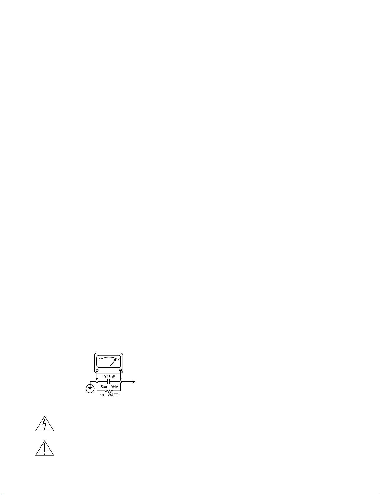
7. AFTER RE-ASSEMBLY OF THE SET ALWAYS PERFORM AN A.C.
LEAKAGE TEST ON ALL EXPOSED METALLIC PARTS OF THE CABINET, (THE CHANNEL SELECTOR KNOB, ANTENNA TERMINALS. HANDLE AND SCREWS) TO BE SURE THE SET IS SAFE TO OPERATE
WITHOUT DANGER OF ELECTRICAL SHOCK. DO NOT USE A LINE
ISOLATION TRANSFORMER DURING THIS TEST USE AN A.C. VOLTMETER, HAVING 5000 OHMS PER VOLT OR MORE SENSITIVITY, IN
THE FOLLOWING MANNER; CONNECT A 1500 OHM 10 WATT RESISTOR, PARALLELED BY A .15 MFD. 150.V A.C TYPE CAPACITOR
BETWEEN A KNOWN GOOD EARTH GROUND (WATER PIPE, CONDUIT, ETC.) AND THE EXPOSED METALLIC PARTS, ONE AT A TIME.
MEASURE THE A.C. VOLTAGE ACROSS THE COMBINATION OF 1500
OHM RESISTOR AND .15 MFD CAPACITOR. REVERSE THE A.C. PLUG
AND REPEAT A.C. VOLTAGE MEASUREMENTS FOR EACH EXPOSED
METALLIC PART. VOLTAGE MEASURED MUST NOT EXCEED 75
VOLTS R.M.S. THIS CORRESPONDS TO 0.5 MILLIAMP A.C ANY
VALUE EXCEEDING THIS LIMIT CONSTITUTES A POTENTIAL SHOCK
HAZARD AND MUST BE CORRECTED IMMEDIATELY.
SUBJECT: GRAPHIC SYMBOLS
THE LIGHTNING FLASH WITH APROWHEAD SYMBOL. WITHIN
AN EQUILATERAL TRIANGLE, IS INTENDED TO ALERT THE
SERVICE PERSONNEL TO THE PRESENCE OF UNINSULATED
“DANGEROUS VOLTAGE” THAT MAY BE OF SUFFICIENT MAG-
NITUDE TO CONSTITUTE A RISK OF ELECTRIC SHOCK.
THE EXCLAMATION POINT WITHIN AN EQUILATERAL TRIANGLE IS INTENDED TO ALERT THE SERVICE PERSONNEL TO
THE PRESENCE OF IMPORTANT SAFETY INFORMATION IN
SERVICE LITERATURE.
SUBJECT : X-RADIATION
1. BE SURE PROCEDURES AND INSTRUCTIONS TO ALL SERVICE PERSONNEL COVER THE SUBJECT OF X-RADIATION. THE ONLY POTENTIAL SOURCE OF X-RAYS IN CURRENT T.V. RECEIVERS IS THE PICTURE TUBE. HOWEVER, THIS TUBE DOES NOT EMIT X-RAYS WHEN
THE HIGH VOLTAGE IS AT THE FACTORY SPECIFIED LEVEL. THE
PROPER VALUE IS GIVEN IN THE APPLICABLE SCHEMATIC. OPERATION AT HIGHER VOLTAGES MAY CAUSE A FAILURE OF THE PICTURE TUBE OR HIGH VOLTAGE SUPPLY AND, UNDER CERTAIN CIRCUMSTANCES, MAY PRODUCE RADIATION IN EXCESS OF DESIRABLE LEVELS.
2. ONLY FACTORY SPECIFIED C.R.T. ANODE CONNECTORS MUST BE
USED. DEGAUSSING SHIELDS ALSO SERVE AS X-RAY SHIELD IN
COLOR SETS, ALWAYS RE-INSTALL THEM.
3. IT IS ESSNTIAL THAT SERVICE PERSONNEL HAVE AVAILABLE AN
ACCURATE AND RELIABLE HIGH VOLTAGE METER. THE CALIBRA
TION OF THE METER SHOULD BE CHECKED PERIODICALLY
AGAINST A REFERENCE STANDARD, SUCH AS THE ONE AVAILABLE
AT YOUR DISTRIBUTOR.
4. WHEN THE HIGH VOLTAGE CIRCUITRY IS OPERATING PROPERLY
THERE IS NO POSSIBILITY OF AN X-RADIATION PROBLEM. EVERY
TIME A COLOR CHASSIS IS SERVICED. THE BRIGHTNESS SHOULD
BE RUN UP AND DOWN WHILE MONITORING THE HIGH VOLTAGE
WITH A METER TO BE CERTAIN THAT THE HIGH VOLTAGE DOES
NOT EXCEED THE SPECIFIED VALUE AND THAT IT IS REGULATING
CORRECTLY, WE SUGGEST THAT YOU AND YOUR SERVICE ORGANIZATION REVIEW TEST PROCEDURES SO THAT VOLTAGE REGULATION IS ALWAYS CHECKED AS A STANDARD SERVICING PROCEDURE. AND THAT THE HIGH VOLTAGE READING BE RECORDER ON
EACH CUSTOMER’S INVOICE.
5. WHEN TROUBLESHOOTING AND MAKING TEST MEASUREMENTS IN
A PRODUCT WITH A PROBLEM OF EXCESSIVE HIGH VOLTAGE,
AVOID BEING UNNECESSARILY CLOSE TO THE PICTURE TUBE AND
THE HIGH VOLTAGE SUPPLY. DO NOT OPERATE THE PRODUCT
LONGER THAN IS NECESSARY TO LOCATE THE CAUSE OF EXCES
SIVE VOLTAGE.
6. REFER TO HV. B+ AND SHUTDOWN ADJUSTMENT PROCEDURES
DESCRIBED IN THE APPROPRIATE SCHEMATIC AND DIAGRAMS
(WHERE USED).
SUBJECT: IMPLOSION
1. ALL DIRECT VIEWED PICTURE TUBES ARE EQUIPPED WITH AN INTE
GRAL IMPLOSION PROTECTION SYSTEM, BUT CARE SHOULD BE
TAKEN TO AVOID DAMAGE DURING INSTALLATION, AVOID
SCRATCHING THE TUBE. IF SCRATCHED REPLACE IT.
2. USE ONLY RECOMMENDED FACTORY REPLACEMENT TUBES.
SUBJECT : TIPS ON PROPER INSTALLATION
1. NEVER INSTALL ANY PRODUCT IN A CLOSED-IN RECESS, CUBBYHOLE OR CLOSELY FITTING SHELF SPACE. OVER OR CLOSE TO
HEAT DUCT, OR IN THE PATH OF HEATED AIR FLOW.
2. AVOID CONDITIONS OF HIGH HUMIDITY SUCH AS: OUTDOOR PATIO
INSTALLATIONS WHERE DEW IS A FACTOR, NEAR STEAM RADIATORS WHERE STEAM LEAKAGE IS A FACTOR, ETC.
3. AVOID PALCEMENT WHERE DRAPERIES MAY OBSTRUCT REAR
VENTING. THE CUSTOMER SHOULD ALSO AVOID THE USE OF DECORATIVE SCARVES OR OTHER COVERINGS WHICH MIGHT
OBSTRUCT VENTILATION.
4. WALL AND SHELF MOUNTED INSTALLATIONS USING A COMMERCIAL MOUNTING KIT. MUST FOLLOW THE FACTORY APPROVED
MOUNTING INSTRUCTIONS A PRODUCT MOUNTED TO A SHELF OR
PLATFORM MUST RETAIN ITS ORIGINAL FEET (OR THE EQUIVALENT
THICKNESS IN SPACERS) TO PROVIDE ADEQUATE AIR FLOW
ACROSS THE BOTTOM, BOLTS OR SCREWS USED FOR FASTENERS
MUST NOT TOUCH ANY PARTS OR WIRING. PERFORM LEAKAGE
TEST ON CUSTOMIZED INSTALLATIONS.
5. CAUTION CUSTOMERS AGAINST THE MOUNTING OF A PRODUCT ON
SLOPING SHELF OR A TILTED POSITION, UNLESS THE PRODUCT IS
PROPERLY SECURED.
6. A PRODUCT ON A ROLL-ABOUT CART SHOULD BE STABLE ON ITS
MOUNTING TO THE CART. CAUTION THE CUSTOMER ON THE HAZARDS OF TRYING TO ROLL A CART WITH SMALL CASTERS ACROSS
THRESHOLDS OR DEEP PILE CARPETS.
7. CAUTION CUSTOMERS AGAINST THE USE OF A CART OR STAND
WHICH HAS NOT BEEN LISTED BY UNDERWRITERS LABORATORIES,
INC. FOR USE WITH THEIR SPECIFIC MODEL OF TELEVISION
RECEIVER OR GENERICALLY APPROVED FOR USE WITH T.V.’S OF
THE SAME OR LARGER SCREEN SIZE.
8. CAUTION CUSTOMERS AGAINST THE USE OF EXTENSION CORDS,
EXPLAIN THAT A FOREST OF EXTENSIONS SPROUTING FROM A SINGLE OUTLET CAN LEAD TO DISASTROUS CONSEQUENCES TO
HOME AND FAMILY.
PRODUCT SAFETY SERVICING GUIDELINES FOR VIDEO PRODUCTS
A.C. VOLTMETER
GOOD EARTH GROUND
SUCH AS THE WATER
PIPE. CONDUIT. ETC
PLACE THIS PROBE
ON EACH EXPOSED
METAL PART
Page 5

1-4
SERVICING PRECAUTIONS
CAUTION : Before servicing the STB covered by this service
data and its supplements and addends, read and follow the
SAFETY PRECAUTIONS. NOTE : if unforeseen circumstances create conflict between the following servicing precautions and any of the safety precautions in this publications, always follow the safety precautions.
Remembers Safety First:
General Servicing Precautions
1. Always unplug the STB AC power cord from the AC
power source before:
(1) Removing or reinstalling any component, circuit board,
module, or any other assembly.
(2) Disconnection or reconnecting any internal electrical
plug or other electrical connection.
(3) Connecting a test substitute in parallel with an elec-
trolytic capacitor.
Caution : A wrong part substitution or incorrect
polarity installation of electrolytic capacitors may result
in an explosion hazard.
2. Do not spray chemicals on or near this STB or any of
its assemblies.
3. Unless specified otherwise in this service data, clean
electrical contacts by applying an appropriate contact
cleaning solution to the contacts with a pipe cleaner,
cotton-tipped swab, or comparable soft applicator.
Unless specified otherwise in this service data, lubrication
of contacts is not required.
4. Do not defeat any plug/socket B+ voltage interlocks with
whitch instruments covered by this service manual might
be equipped.
5. Do not apply AC power to this STB and/or any of its
electrical assemblies unless all solid-state device heat
sinks are cerrectly installed.
6. Always connect test instrument ground lead to the
appropriate ground before connection the test instrument
positive lead. Always remove the test instrument ground
lead last.
Insulation Checking Procedure
Disconnect the attachment plug from the AC outlet and turn
the power on. Connect an insulation resistance meter(500V)
to the blades of the attachment plug. The insulation resistance between each blade of the attachment plug and accessible conductive parts (Note 1) should be more than 1Mohm.
Note 1 : Accessible Conductive Parts including Metal panels, Input terminals, Earphone jacks, etc.
Electrostatically Sensitive (ES) Devices
Some semiconductor (solid state) devices can be damaged
easily by static electricity. Such components commonly are
called Electrostatically Sensitive (ES) Devices. Examples of
typical ES devices are integrated circuits and some field
effect transistors and semiconductor chip components.
The following techniques should be used to help reduce the
incidence of component damage caused by static electricity.
1. Immediately before handling any semiconductor component or semiconductor-equipped assembly, drain off any
electrostatic charge on your body by touching a known
earth ground. Alternatively, obtain and wear a commercially available discharging wrist strap device, which
should be removed for potential shock reasons prior to
applying power to the unit under test.
2. After removing an electrical assembly equipped with ES
devices, place the assembly on a conductive surface such
as aluminum foil, to prevent electrostatic charge buildup or
exposure of the assembly.
3. Use only a grouned-tip soldering iron to solder or unsolder
ES devices.
4. Use only an anti-static solder removal device. Some
solder removal devices not classified a “anti-static” can
generate electrical charges sufficient to damage ES
devices.
5. Do not use freon-propelled chemicals. These can
generate electrical charge sufficient to damage ES
devices.
6. Do not remove a replacement ES device from its protec
tive package until immediately before you are ready to
install it. (Most replacement ES devices are packaged with
leads electrically shorted together by conductive foam,
aluminum foil, or comparable conductive material).
7. Immediately before removing the protective material from
the leads of a replacement ES device, touch the protective
material to the chassis or circuit assembly into which the
device will be installed.
Caution : Be sure no power is applied to the chassis or
circuit, and observe all other safety precautions.
8. Minimize bodily motions when handling unpackaged
replacement ES devices. (Normally harmless motion such
as the brushing together of your clothes fabric or the lifting
of your foot from a carpeted floor can generate static electricity sufficient to damage an ES device.)
Page 6

1-5
SPECIFICATIONS
Television System NTSC, DTV standard (1080i, 720p, 480p, 480i)
Channel Coverage Terrestrial: 2-69, Cable: 1-135
Input/Output
ATSC ANT Input ANT IN (1) (ATSC-8VSB over Terrestrial or QAM over cable)
ANT Loop Out Out To TV (1)
DVI Output DVI-HDTV Out (1), DVI-D Single Link connector
1080i, 720p, 480p digital RGB
Component Video Output Component Out (1 Set), Typical RCA type Jack connectors
1080i, 720p, 480p, 480i YPbPr
RGB Output RGB Out (1), 15-pin connector
1080i, 720p, 480p RGB
S-Video Output S-Video Out (1), 4-pin Mini-DIN
480i Y/C
Video Output Video Out (1), Typical RCA type Jack connector
480i Composite
Digital Audio Output Coaxial, Optical (Dolby Digital output)
Analog Audio Output Audio Out (2) (Variable Output Level)
Authorized Service Port 9-pin Serial Port (1)
Dimension (W x H X D) 14.2 x 2.4 x 10.4 inches (360 x 60 x 265 mm)
Weight 7.7 lbs (3.5 kg)
Power Requirements AC 120V, 60Hz
Power Consumption 15W
Environment
Humidity 0 to 99 percent non condensing
Storage Temperature -20 to 60 degrees Celsius (-4 to 140 degrees Fahrenheit)
Operating Temperature 0 to 40 degrees Celsius (32 to 104 degrees Fahrenheit)
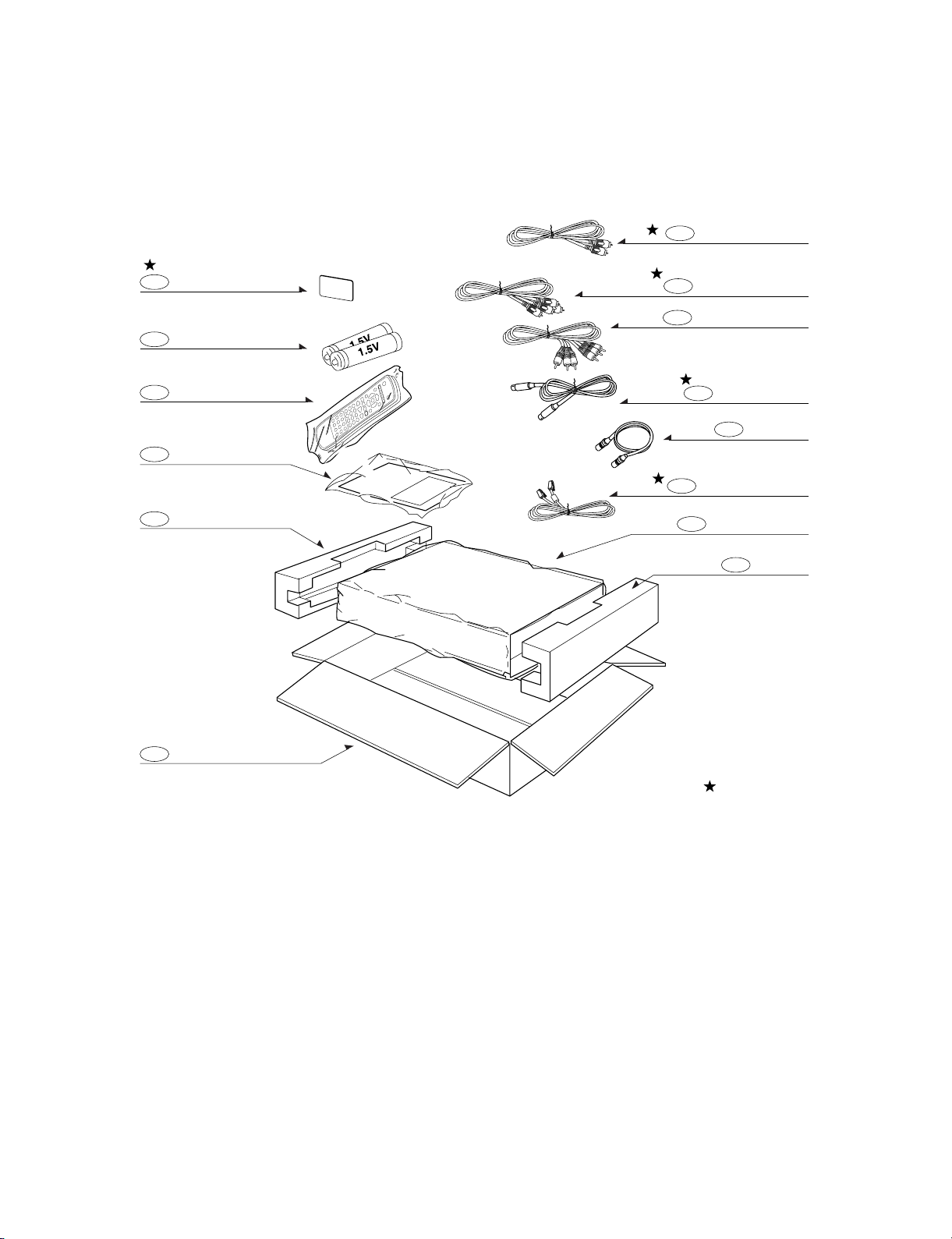
Accessories
RF cable . . . . . . . . . . . . . . . . . . . . .1
Video cable . . . . . . . . . . . . . . . . . . .1
Audio (L/R) cable . . . . . . . . . . . . . . .1
Component (YPbPr) cable . . . . . . . .1
Remote Control . . . . . . . . . . . . . . . .1
Batteries (size AA) . . . . . . . . . . . . . .2
Page 7

2-1
SECTION 2
CABINET & MAIN CHASSIS
CONTENTS
EXPLODED VIEWS .....................................................................................................................2-2
1. Cabinet and Main Frame Section ...........................................................................................2-2
2. Packing Accessory Section....................................................................................................2-3
Page 8

2-2
EXPLODED VIEWS
1. Cabinet and Main Frame Section
300
A47
463
463
463
463
250
A46
463
463
A43
A44
A49
280
452
452
260
320
466
457
465
466
469
470
457
A
5
4
3
2
1
BCD
Page 9
2-3
2. Packing Accessory Section
808
804
803
801
900
802
803
813
S-VIDEO CABLE
806
RF CABLE
823
TELEPHONE LINE
820
PLUG ASS'Y(3WAY)
PACKING SHEET
PACKING
BATTERY
822
SMART CARD
REMOCON
BOX CARTONX
PACKING
OWNER'S MANUAL
OPTIONAL PARTS
811
812
PLUG ASS'Y 1WAY
PLUG ASS'Y 2WAY
Page 10

3-1
SECTION 3
ELECTRICAL
CONTENTS
SOFTWARE CORRUPTION PROBLEM.....................................................................................................3-2
ELECTRICAL TROUBLESHOOTING GUIDE............................................................................................3-5
1. POWER(SMPS) CIRCUIT.........................................................................................................................3-5
2. AUDIO CIRCUIT .......................................................................................................................................3-7
1) NO ATSC AUDIO.....................................................................................................................................3-7
2) NO OPTICAL OUTPUT AUDIO...............................................................................................................3-11
3) NO COAXIAL OUTPUT AUDIO ..............................................................................................................3-12
3. CPU (SYSTEM CONTROL) TROUBLESHOOTING ..............................................................................3-14
4. VIDEO TROUBLESHOOTING FLOW ....................................................................................................3-21
5. ATSC/ QAM FRONT- END TROUBLESHOOTING FLOW ....................................................................3-31
6. FRONT PANEL TROUBLESHOOTING FLOW......................................................................................3-32
OVERALL BLOCK DIAGRAM.........................................................................................................................3-34
1. OVERALL BLOCK DIAGRAM 1 ............................................................................................................3-34
2. OVERALL BLOCK DIAGRAM 2 ............................................................................................................3-36
3. OVERALL BLOCK DIAGRAM 3 ............................................................................................................3-38
BLOCK DIAGRAM & SIGNAL FLOW.............................................................................................................3-40
1. POWER(SMPS) BLOCK DIAGRAM ......................................................................................................3-40
2. SYSTEM CONTRL BLOCK DIAGRAM..................................................................................................3-42
3. AUDIO PROCESSING BLOCK DIAGRAM............................................................................................3-44
4. VIDEO PROCESSING BLOCK DIAGRAM ............................................................................................3-46
CIRCUIT DIAGRAM .........................................................................................................................................3-48
1. POWER(SMPS) CIRCUIT DIAGRAM ....................................................................................................3-48
2. CPU, AUDIO, POWER CIRCUIT DIAGRAM..........................................................................................3-50
3. HD2, TUNER, DVI CIRCUIT DIAGRAM.................................................................................................3-52
4. ATSCII-STB CIRCUIT DIAGRAM...........................................................................................................3-54
5. FRONT CIRCUIT DIAGRAM ..................................................................................................................3-56
PRINTED CIRCUIT DIAGRAMS......................................................................................................................3-58
1. DIGITAL MAIN P.C.BOARD(BOTTOM)..................................................................................................3-58
2. DIGITAL MAIN P.C.BOARD(TOP)..........................................................................................................3-60
3. FRONT P.C.BOARD ...............................................................................................................................3-62
4. POWER P.C.BOARD ..............................................................................................................................3-62
Page 11
SOFTWARE CORRUPTION PROBLEM
3-2
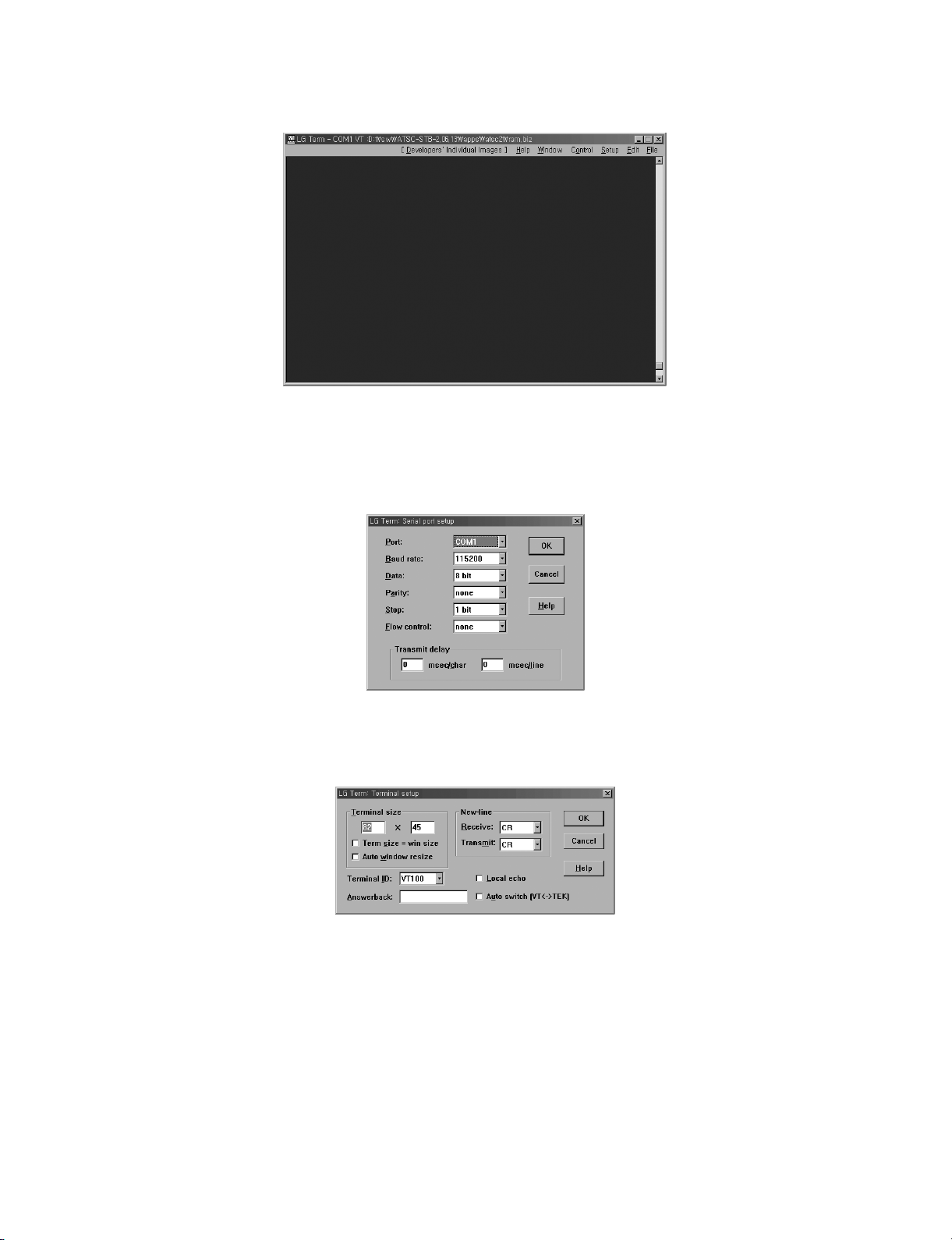
1. Open window display for Serial Communication like above.
- You can use almost kinds of serial communication programs, but we send the terminal
(LG Term) which is now used on our side.
2. Create “Setup-> Serial Port” like the display. (However, the port depends upon the user
environment so that you need to create properly.)
3. Create “Setup-> Terminal” like the above display.
Page 12

3-3
4. After completing all set-up process, press d key in the terminal and impress STB power.
At this time, you should pull up the plug and then pull into the socket again.
- You have another choice. When activating, please enter “klLST3100”, “ENTER” and
then “F10” keys in sequence. Once the command mode is up, you can download it
even in your “Reset” command.
5. When above display shows up, you can download applications. You can input keys at the
prompt.
6. Press Enter Key several times to input new command. Input serial download command
as “sto ser” like above example and then press Enter key.
7. This is the condition you can download application program from STB.
Page 13

3-4
8. In the downloadable condition, select °∞File->Send File°±. You can watch one more dis-
play like above. You should find °∞ram.biz°∞ file in this new display and open it to start
downloading.
9. You can see the downloading process from display and it takes about 2 minutes to complete. After downloading, the message °∞Please write data into the Flash ROM°± would
show up. (You may experience errors of downloading. Then, follow from No. 6 again.
10. Above message shows that you succeed to write application program into the Flash.
Restart the power source, or input °∞b flash°± in this display to activate properly.
(If you have no response, please input command again.)
Page 14
3-5
ELECTRICAL TROUBLESHOOTING GUIDE
1. Power(SMPS) CIRCUIT
NO
NO
NO
NO
NO
NO
NO
NO
NO
YES
YES
YES
YES YES
YES
NO
YES
YES
YES
YES
YES
YES
YES
YES
YES
(1) No 5.0VA
Check or Replace
the D106
Check the ‘PWR CTL
“H”’ signal from µ-com
NO
NO
(2) No 5.0V
NO
(3) No 3.3V
No 5.0VA
Is the F101 normal?
Is the R105
Normal?
Is the BD101
normal?
Is Vcc (13V - 16V) supplied to IC101 Pin7?
Are the D106
normal?
Is there about 2.5V
at the IC103 Pin1?
Is the D105
normal?
Is the D109
normal?
Replace the F101.
(Use the same Fuse)
Replace the
BD101.
Replace the R105.
Is the D103
normal?
Check or Replace
the D106.
Replace the
D106.
Replace the IC103.
Replace the
D105.
Replace the
D109.
Replace the
D110.
No 3.3V
Is there about 3.8V
at the IC153 pin1?
Is there about 3.3V~
5V at the IC153 pin4?
YES
Check the IC153
and Replace
Check or Replace
the D105
NO
Check the ‘PWR CTL
“H”’ signal from µ-com
Is there about 5.4V
at the IC152 pin1?
Is there about 3.3V~5V
at the IC152 pin4?
YES
Check the IC152
and Replace
Is the D110
normal?
NO
Replace the
D108.
Is the D108
Normal?
NO 5.0V
YES
YES
Power Line of Main
PCB is short
NO
Replace the
D107.
Is the D107
Normal?
Page 15
3-6
YES
YES
NO
(4) No 12VA
Is there about 13V
at the IC155 pin1?
Is there about 3.3V~5V
at the IC155 pin4?
Check the IC155
and Replace
Check or Replace
the D109
NO
Check the ‘PWR CTL
“H”’ signal from µ-com
YES
YES
YES
YES
NO
NO
NO
(6) No VFD
No VFD
Is The R123
Normal?
Is The D107
Normal?
Is The ZD102
Normal?
Check and
Replace the D108
Replace the R123
Replace the R107
Replace the ZD102
YES
YES
NO
(5) No 30VA
No 30VA
Is The ZD110
Normal?
Check and
Replace the D110
Replace the ZD101
Page 16

3-7
2. AUDIO CIRCUIT
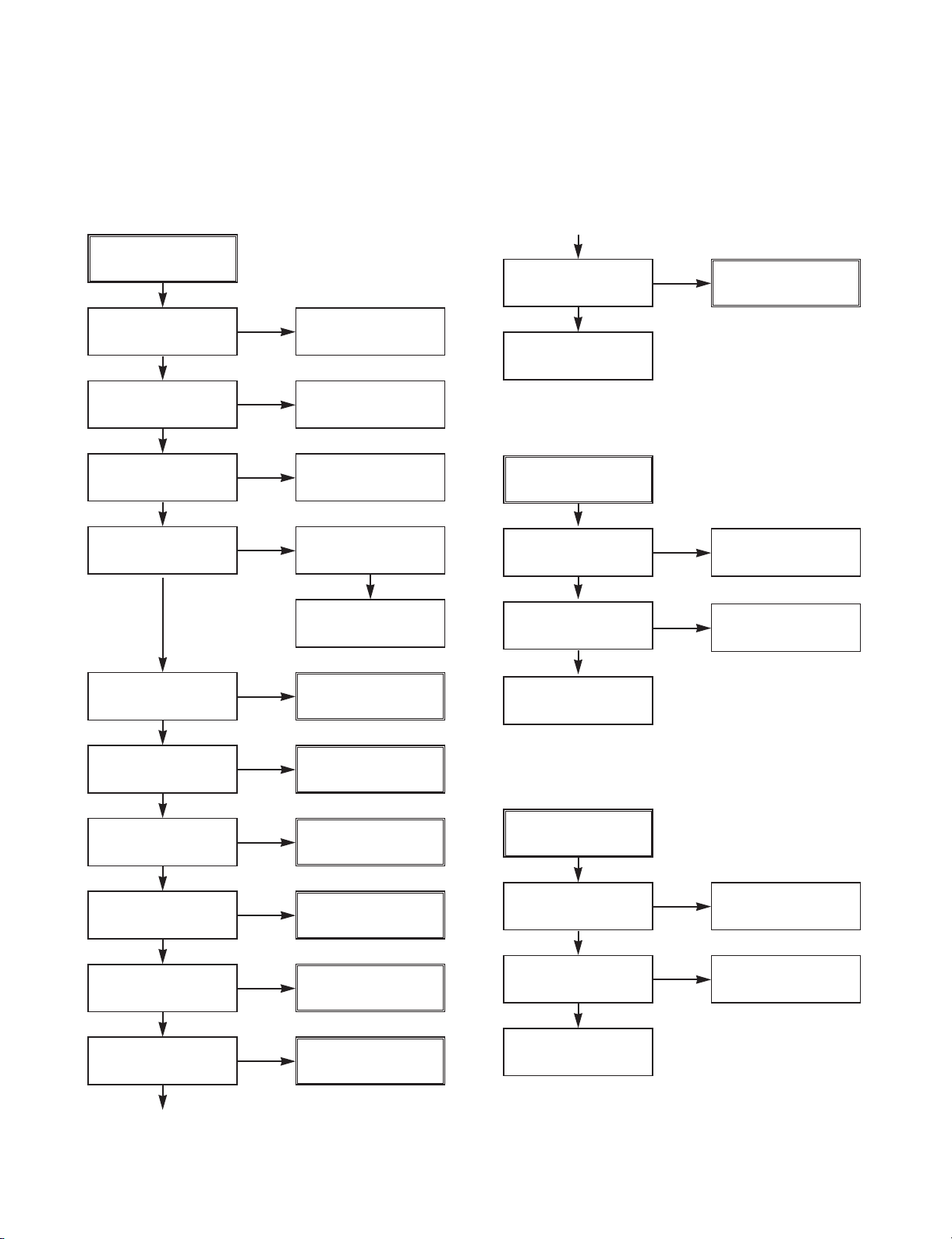
1) NO ATSC AUDIO
NO
NO
NO
NO
NO
YES
YES
YES
YES
(1) Check IC110 and Surroundings
5V is supplied to IC110(14)?
12.2880MHz clock is input to IC110
(5)? Fig. 01
IC110(13) is grounded?
48KHz clock is output from IC110
(4)? Fig. 02
Data Signal is input to IC110(2)?
Fig. 03
YES
Analog Audio Signal from IC110
(12,15)? Fig. 04
Check the Power Supply Part.
Check 12.2880MHz Clock output at
IC200(H5).
Check 48KHz Clock ouput at IC200
(G5)
Check soldering.
Check Data Signal at IC200(G3)
Page 17
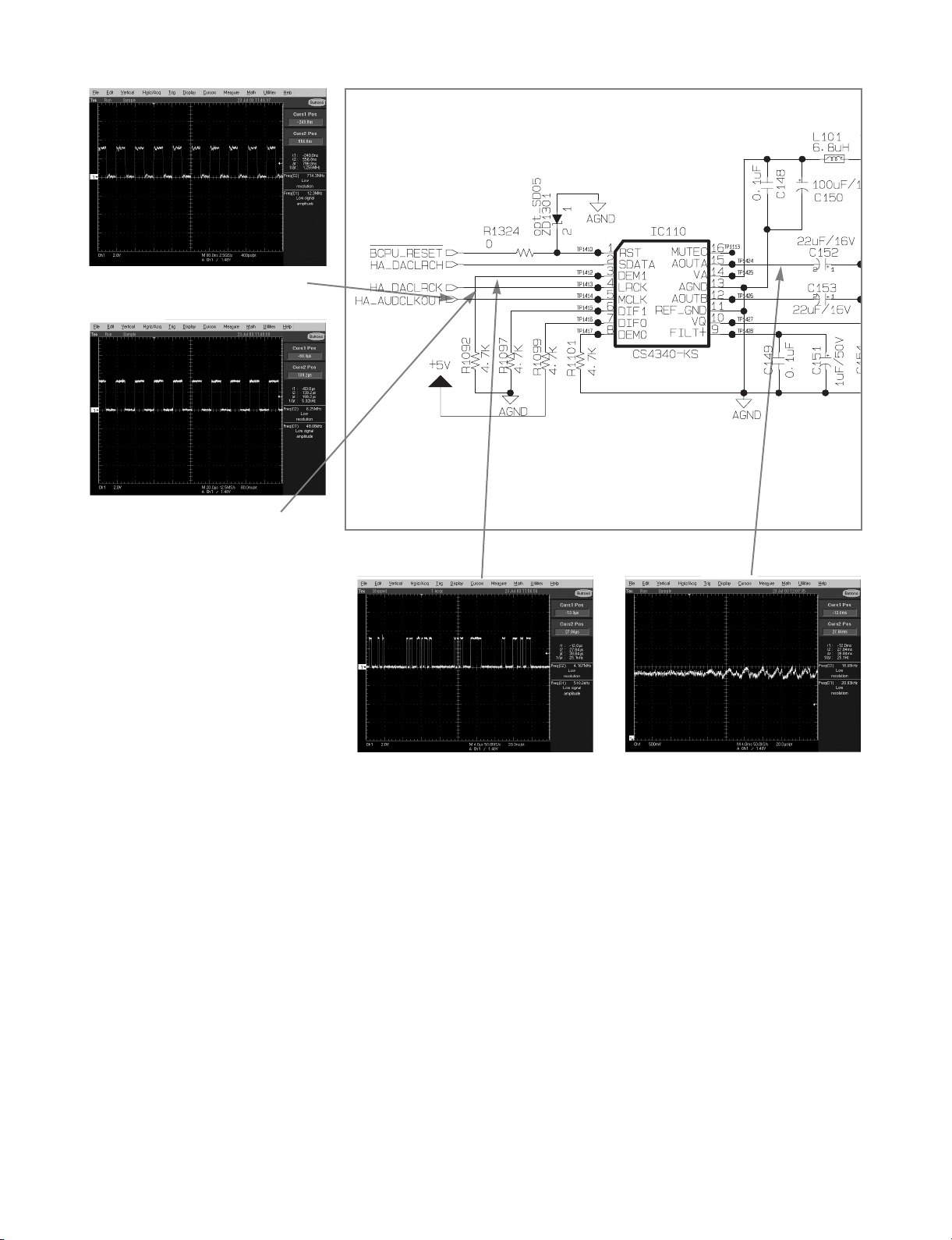
3-8
Fig. 01 12.2880MHz clock
Fig. 02 48KHz clock
Fig. 04 Analog Audio SignalFig. 03 Data Signal
Page 18
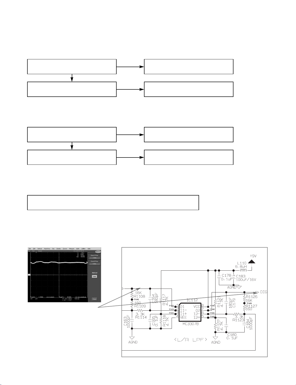
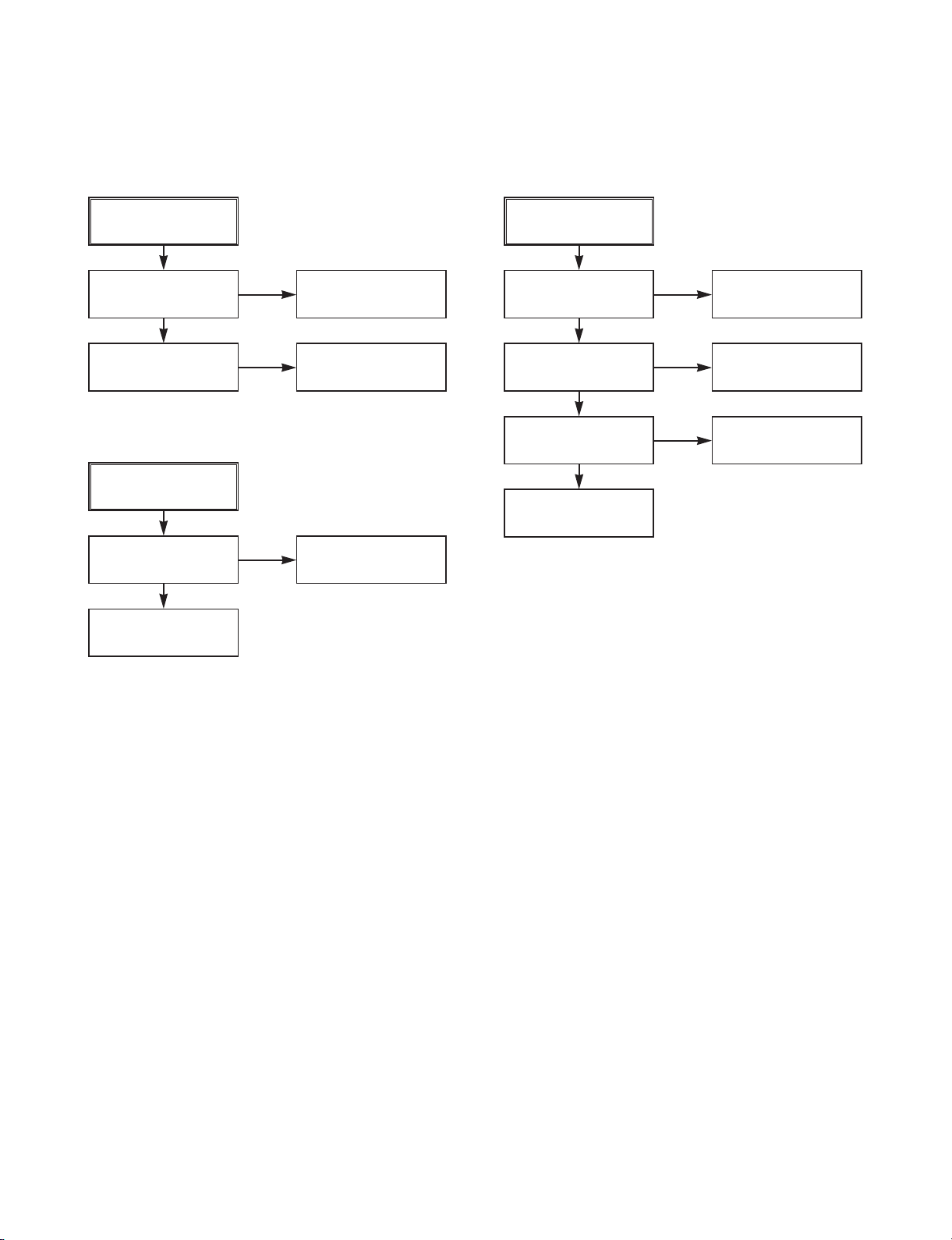
3-9
Fig. 05 Analog Audio Signal
NO
NO
NO
YES
YES
(2) Check IC112 and Surroundings
(3) Check Q102, Q103, Q109, Q110 and Surroundings
(4) Check Output Jack and Surroundings
59V is supplied to IC112(8)?
Analog audio signal is output from
IC112(1, 7)? Fig. 05
Analog audio signal is output from
Q102, Q103, Q109, Q110(1)? Fig. 06
9V is supplied to Q102, Q103,
Q109,Q110(3)?
Check CN300(VARIABLE_ L, VARIABLE_ R, MONITOR_ L, MONITOR_ R)
And their surroundings
Check Power Supply Part
Check IC112 and surroundings
NO
Check Power Supply Part
Check Q102, Q103, Q109, Q110 and
surroundings
Page 19

3-10
Fig. 06 Analog Audio Signal
Page 20

3-11
2) NO OPTICAL OUTPUT AUDIO
NO
YES
SPDIF pulse is output from IC200
(F3)? Fig. 07
Check CN103 and surrounding
Check IC200 and surroundings
Page 21
3-12
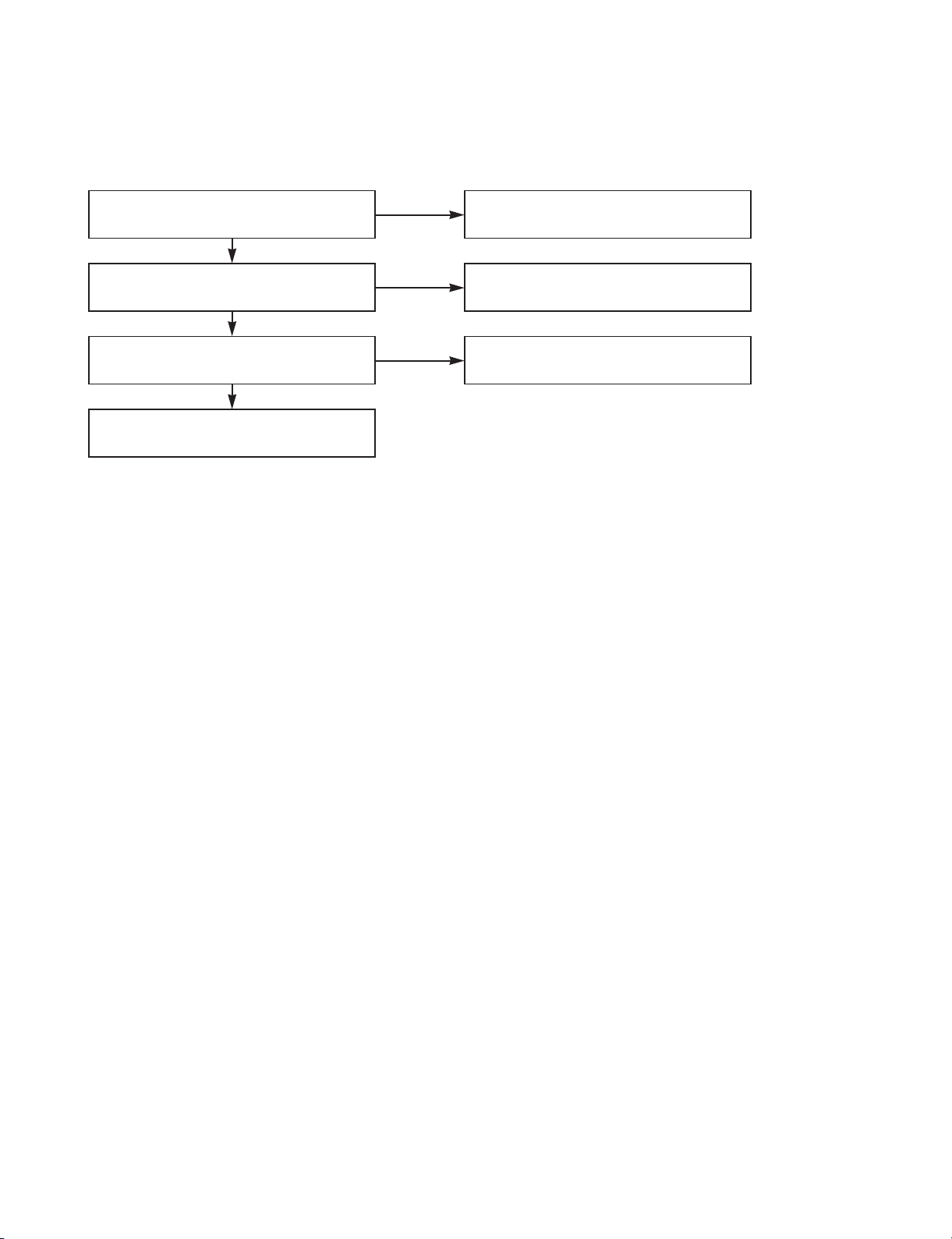
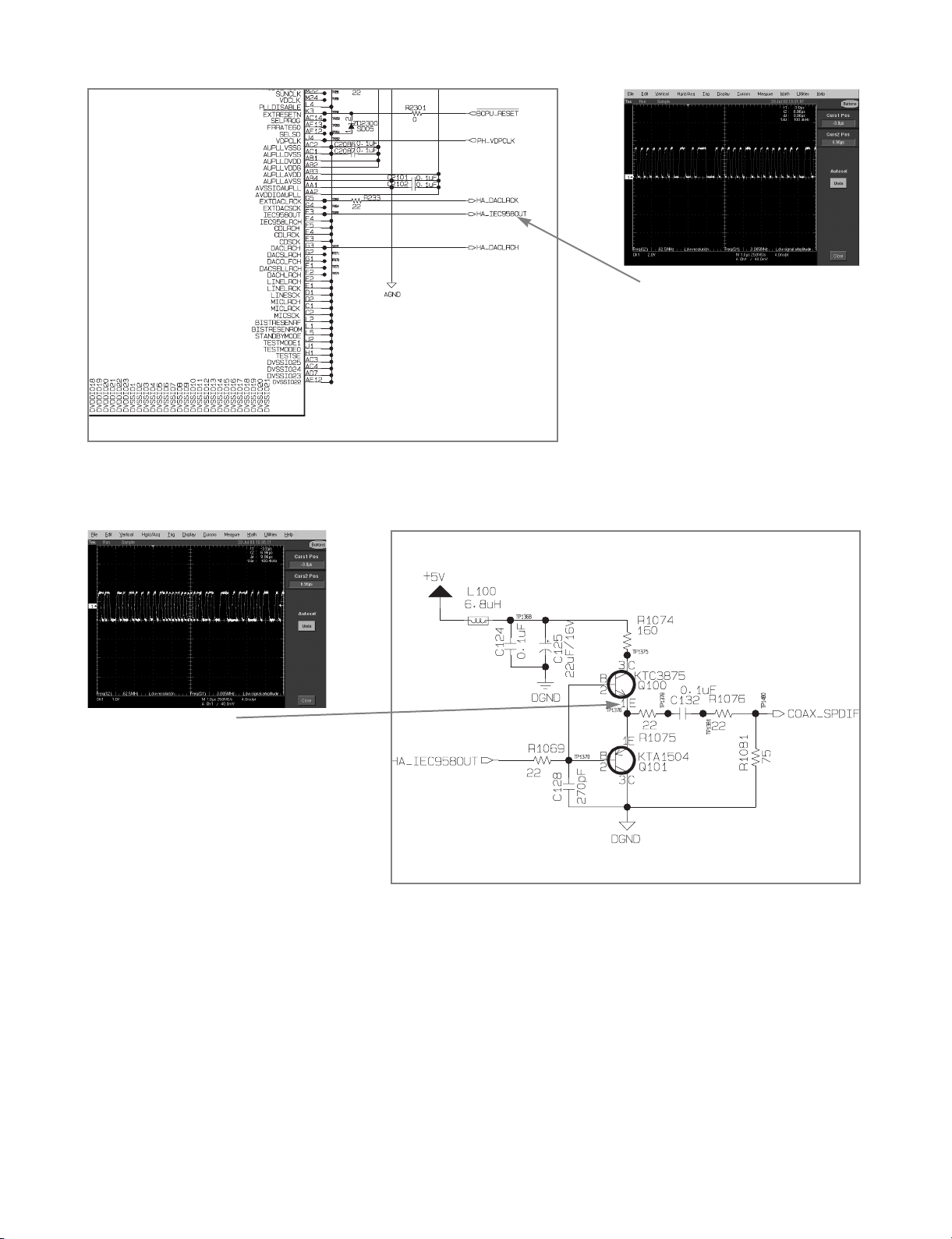
3) NO COAXIAL OUTPUT AUDIO
NO
NO
NO
YES
YES
YES
5V is supplied to Q100(3)?
SPDIF pulse is output from IC200(F3)?
Fig. 07
SPDIF pulse is output from Q100(1)?
Fig. 08
Check CN300(S6, G6) and their
surroundings
Check Power Supply Part
Check IC200 and surroundings
Check Q100, Q101 and surroundings
Page 22
3-13
Fig. 07 ,Digital Audio Signal
Fig. 08
Coaxial Digital Audio Signal
Page 23

3. CPU (System Control) Troubleshooting
NO
YES
YES
Start
Is Power supplied normally?
Is each clock OK?
YES
Is each reset OK at the time of
power- on reset?
YES
Is each chip selection OK?
YES
Is each I2C channel OK?
YES
Are messages output through
RS- 232C port on PC terminal?
YES
End
Check Power : Refer to (A)
NO
NO
NO
NO
NO
Check each clock : Refer to (B)
Check reset circuit : Refer to (C)
Check each chip selection : Refer to (D)
Check each I2C channel : Refer to (E)
Check RS- 232C circuit : Refer to (G)
3-14
Page 24

3-15
NO
YES
YES
(A)
Is 2.5V supplied to the pin 21 of IC109
and 3.3V to the pin 9 of IC109 ?
Is 3.3V supplied to the pin 37 of IC100,
101 and the pin 1 of IC106, 107 ?
YES
Check IC100, 101, 106, 107, 109
Power Supply Check
IC113 : 2.5V IC111 : 3.3V
NO
Power Supply Check
IC111 : 3.3V
Page 25

3-16
Fig. 02Fig. 01
NO
YES
YES
(B)
Is 10MHz clock output from X101 ?
Fig. 01
Is 60MHz clock output from the pin 28
of IC109? Fig. 02
Check X101
NO
Check IC109
Page 26

3-17
Fig. 04Fig. 03
NO
YES
YES
(C)
Is the pin 3 of IC103 reset ?
Is the pin 4 of IC104 reset ? Fig. 03
YES
Is the pin 93 of IC109 reset ?
YES
Is the pin 10 of IC104 reset at the
time of power- button on? Fig. 04
IC103 Check
NO
NO
NO
IC104 Check
IC109 Check
IC104 Check
Page 27

3-18
Fig. 05
NO
YES
YES
(D)
Is logic low pulse seen at R1060?
Is logic low pulse seen at R1054?
Fig. 05
YES
Is logic low pulse seen at R1061?
Check IC109, 100, 101
NO
NO
Check IC109, 106, 107
Check IC109, 200
Page 28

3-19
Fig. 07Fig. 06
NO
YES
YES
(E)
Are IIC SCL and SDA signals output from
the pin 60, 61 of IC109 ? Fig. 06 & Fig. 07
A re IIC SCL and SDA signal input to
the pin 1, 2 of IC108 from IC109 ?
YES
Are IIC SCL and SDA signals output
from the pin 6, 7 of IC108?
Check IC109
NO
NO
Check IC108, IC109
Check IC108, 105,
Page 29

3-20
Fig. 08
NO
YES
YES
(F)
Is RS- 232C port setup OK?
(Baudrate, Parity, Data Bit, Stop Bit)
Is the pin 11 of IC102 OK?
(TxD signal) Fig. 08
YES
Is the pin 12 of IC102 OK?
(RxD signal)
Modify RS- 232C port setup
NO
NO
Check IC109, IC102
Check IC109, IC102
Page 30

3-21
4. VIDEO Troubleshooting Flow
NO
YES
YES
START
No HV sync OUT?
Any problem in OSD ?
Any problem in main picture?
Any problem in AV out?
End
YES
YES
YES
(A)
NO
NO
NO
NO
(B)
(C)
(D)
(E)
Page 31

3-23
FIG. 04 V- sync signal
FIG. 03 H- sync signal
Page 32

3-24
YES
NO
(C)
Check input stream existence.
Any problem?
Any problem in selecting ATSC?
Any decoding problem?
End
NO
NO
check VSB(IC203 ) block. FIG. 05
YES
YES
OK
Check voltage of IC203(23) => 3.3V
Check signal strength. If OK, check
system clock 27MHz. IC300(9)
Check HD 2 chip Interrupt FIG. 06
YES
NO
(B)
Check whether analog mute ON?
Check analog buffers. IC303 for 480i, IC302
for component YPbPr or RGB analog
Jump to (A) flow
OK
No OSD is not a problem.
Check DVI output.
YES
Check whether +A12V is supplied.
Page 33

3-25
FIG. 05
Input Stream to IC203
FIG. 06
Interrupt Signal
Page 34

3-26
Page 35

3-27
Page 36

3-28
YES
(D)
Check analog buffers.
IC303 for 480i
Jump to (A) flow
Page 37

3-29
NO
YES
START
Is DVI cable connected?
Is Display Format front pane DVI side?
Is The emitter of Q201 high volt ?
Is IC206(11) high volt ?
YES
YES
Is 480P picture OK?
YES
Are 720P & 1080I picture OK?
END
YES
YES
Connect DVI cable
NO
NO
NO
NO
NO
Change to DVI side
Use other DVI cable or Turn on the monitor that is connected with DVI cable.
Change the DVI chip
Check IC206(57(IDCK+), 2(DE),
4(HSYNC), 5(VSYNC)) The IDCK_
clock shall be 27MHz. Refer to Fig. 1
Check IC206(57(IDCK+), 2(DE), 4(HSYNC),
5(VSYNC)) The IDCK_ clock shall be
74.25MHz. Refer to Fig2, Fig3 and Fig4.
Page 38

3-30
FIG. 01
DVI output at 480p
FIG. 04
DVI output at 1080i odd field
FIG. 03
DVI output at 1080i even field
FIG. 02
DVI output at 720p
Page 39

3-31
5. ATSC/ QAM Front- End Troubleshooting Flow
YES
YES
START
Is Power supplied normally?
Is RF signal detected?
(using Spectrum Analyzer)
Check IC203’s output signals of
DATA( Fig. 01 ) (AR200,AR201),
packet valid signal( Fig. 02 )(AR202
or the pin 27 of IC203) and Byte
clock(the pin 30 of CN2301)
( Fig. 03 )
YES
YES
Check the power lines referring
the circuit diagram
Change channel with DTV signal
Check the status of connection on PCB.
Check Error flag LED. (LD200)
OFF: normal, ON: Error
END
YES
Check the NIM Tuner(IC203) and
peripheral parts
FIG. 03FIG. 02FIG. 01
Page 40

3-32
6. FRONT PANEL Troubleshooting Flow
NO
NO
NO
NO
NO
YES
YES
1) If front panel board is not working
START
The IC 5V power is supplied normally?
The IC -28, -24, -21.5V powers are
supplied normally?
The clock #1 operates normally?
The signal #2 operates normally?
YES
YES
Check IC100(13), IC100(43),
IR100(2) voltage : 5V
Check Connector P101(3), P101(2),
P101(1) voltage : -28, -24, -21.5V
Check IC100(5) clock waveform
: See FIG. 01
Check IC100(8) clock waveform
: See FIG. 02
The signal #3 operates normally?
END
YES
Check IC100(42) clock waveform
: See FIG. 03
Page 41

3-33
FIG. 03
IC100(42) VFD Chip Grid1 Pulse
FIG. 02
IC100(8) VFD Control Clock Signal
FIG. 01
IC100(5) VFD Chip Clock
Page 42

3-34 3-35
OVERALL BLOCK DIAGRAM
1. OVERALL BLOCK DIAGRAM 1
Board-to-Board Connection
FRONT Board
MAIN Board
SMPS
Board
15FD(+)/-21.5V15
14FD(-)/-24V14
13GND13
12-28V12
11GND11
103.3V10
93.3V9
85V8
75V7
6GND6
59V5
412V4
3GND3
230V2
1PW R_CTRL1
12
1110
9
87
6
54
3
21
GND
IR_DATA
DATA_RD
DATA_WR
CLK
CS
5
V
GND
GND
-
28
V
FD(-)/-
24
V
FD(+)/-
21
.
5
V
12
1110
9
87
6
54
3
21
AC120V
Page 43

3-36 3-37
2. OVERALL BLOCK DIAGRAM 2
RF IN
Loop
Through
Tuner
5V I2C
ATSC NIM TUNER
CPU
(S3C44B0X)
60MHz
SDRAM
(4Mx16bx2)
Flash ROM
(512Kx16bx2)
EEPROM
(32Kx8b)
CPU I/F
3V I2C
CPU CLK
RS232
Driver
(MAX232)
UART
Sys Reset
(KIA7029 &
74HC14)
RS-232C
10 MHz
X-tal
YPbPr Video Out
AMP
(LMH6683)
Line Driver
(74HC540)
RGB
Hs/Vs
RGB Video Out
TP Demux
Video Decoder
Audio Decoder
Format Converter
VDP
(LGDT1102A
: HD-II)
LPF
(TOKO 25M)
X 3
Main PW M
Main VDP Clock
Clock Gen.
(CY24206)
NT2CLK
SYSCLK
DVI
Transmitter
(Sil170)
TMDS CH0,1,2
TMDS CLK +-
I2C Ext.
(82B715)
5V I2C
DVI Out
Digital RGB
Hs, Vs
3V I2C
SDRAM
(2Mx32bx2)
ATSC TP
Digital
Audio Out
2CH L/R
Audio Out
LPF
(MC33078)
Digital Audio
Optical Out
DAC
(CS4340)
Digital Audio
Coaxial Out
AC120V
+30V
+12V
+9V
+5V
+5V_Alive
+3.3V
-28V
-24V
-21.5V
SMPS
Power Control
Variable
Audio Out X2
I2C Hub
I2CI2C
5V I2C
VCR Out
S-Video Out
VCR out (Comp.)
VCR out (Y/C)
AMP
(LMH6683)
RGB
DVI 5V I2C
Sil 170
+5V_Alive
3.3V
Regulator
+3.3V_Alive
2.5V
Regulator
+2.5V_Alive
+3.3V
1.8V
Regulator
+1.8V
VFD
Controller
Front Panel
VFD
Key Scan
Key Block
IR
Receiver
VCXO IC
(CY24212)
IC203
IC105
IC108
IC103, IC104
IC102
IC109
IC100, IC101 IC106, IC107
IC111
IC113
IC114
IC110 IC112
X101
X3300
27 MHz
X-tal
IC200
IC201, IC202
IC206
IC207
IC205
Buffer
(74LCX157)
Mute Control
IC2300
IC3300
IC300
IC302
IC303
FL300~302
Page 44

3-38 3-39
3. OVERALL BLOCK DIAGRAM 3
RF IN
Loop
Through
Tuner
5V I2C
ATSC NIM TUNER
CPU
(S3C44B0X)
60MHz
SDRAM
(4Mx16bx2)
Flash ROM
(512Kx16bx2)
EEPROM
(32Kx8b)
CPU I/F
3V I2C
CPU CLK
RS232
Driver
(MAX232)
UART
Sys Reset
(KIA7029 &
74HC14)
RS-232C
10 MHz
X-tal
YPbPr Video Out
AMP
(LMH6683)
Line Driver
(74HC540)
RGB
Hs/Vs
RGB Video Out
TP Demux
Video Decoder
Audio Decoder
Format Converter
VDP
(LGDT1102A
: HD-II)
LPF
(TOKO 25M)
X 3
Main PW M
Main VDP Clock
Clock Gen.
(CY24206)
NT2CLK
SYSCLK
DVI
Transmitter
(Sil170)
TMDS CH0,1,2
TMDS CLK +-
I2C Ext.
(82B715)
5V I2C
DVI Out
Digital RGB
Hs, Vs
3V I2C
SDRAM
(2Mx32bx2)
ATSC TP
Digital
Audio Out
2CH L/R
Audio Out
LPF
(MC33078)
Digital Audio
Optical Out
DAC
(CS4340)
Digital Audio
Coaxial Out
AC120V
+30V
+12V
+9V
+5V
+5V_Alive
+3.3V
-28V
-24V
-21.5V
SMPS
Power Control
Variable
Audio Out X2
I2C Hub
I2CI2C
5V I2C
VCR Out
S-Video Out
VCR out (Comp.)
VCR out (Y/C)
AMP
(LMH6683)
RGB
DVI 5V I2C
Sil 170
+5V_Alive
3.3V
Regulator
+3.3V_Alive
2.5V
Regulator
+2.5V_Alive
+3.3V
1.8V
Regulator
+1.8V
VFD
Controller
Front Panel
VFD
Key Scan
Key Block
IR
Receiver
VCXO IC
(CY24212)
IC203
IC105
IC108
IC103, IC104
IC102
IC109
IC100, IC101 IC106, IC107
IC111
IC113
IC114
IC110 IC112
X101
X3300
27 MHz
X-tal
IC200
IC201, IC202
IC206
IC207
IC205
Buffer
(74LCX157)
Mute Control
IC2300
IC3300
IC300
IC302
IC303
FL300~302
: Video Signal
: Audio Signal
: Digital Video Signal
: Digital Audio Signal
Page 45

3-40 3-41
PHOTO COUPLER
(IC102)
T101
TRANS
RECTIFIER &
SMOOTING BLOCK
(D107,C126)
P. CTL ëHí
30VA
9VA
ERROR
AMP
(IC103)
13
12
10
7
11
14
15
FEED-BACK
BLOCK
R116,R117,
C114,R118.
R119.R120
R121)
RECTIFIER &
SMOOTING BLOCK
(D108,C124,L106,C125)
RECTIFIER &
SMOOTING BLOCK
(D110,C122)
RECTIFIER &
SMOOTING BLOCK
(D105,C118,
L104,C119)
RECTIFIER &
SMOOTING BLOCK
(D109,C120)
RECTIFIER &
SMOOTING BLOCK
(D106,C116,
L103,C117)
5V
5VA
TO Main
(P101)
8
9
9V REG & S/W
BLOCK
(IC154,C154,R154)
12V REG & S/W
BLOCK
(IC155,C155,R151)
3.3V REG & S/W
BLOCK
(IC153,C153,R152)
5.0VA REG
BLOCK
(IC156,C156)
5.0V REG & S/W
BLOCK
(IC152,C152,R153)
FD(+)
FD(-)
-29VA
FUSE
(F101)
NOISE FILTER
BLOCK
(C101,L101,
C102)
SNUBBER
BLOCK
(D102,C105
C106,R104)
DRIVE & S/W BLOCK
(IC101, D103, R103,
C111, C109 , R101,
R102,R106,BC101)
BD101
R105
1
3
5
6
Y-CAP
C113
Y-CAP
C112
+
BR BL
(BK)(WH)
C103
!
!
!
!
!
!
3.3V
12VA
BLOCK DIAGRAM & SIGNAL FLOW
1. POWER(SMPS) BLOCK DIAGRAM
Page 46

3-42 3-43
2. SYSTEM CONTRL BLOCK DIAGRAM
CPU
DATA BUS[16-31]
DATA BUS[0-15]
FLASH ROM
(512Kx16b)
FLASH ROM
(512Kx16b)
A[2-20]
A[2-20]
SDRAM
(8Mx16b)
SDRAM
(8Mx16b)
ADDRESS BUS[1-23]
HD2
Addr[23,22,13-2]
Addr[23,22,13-2]
OE
WE
GCS0
GCS1
OEWE
OEWE
GCS6/SCS0
DQM0/DQM1/WE/CA
S/RAS/CLK/CKE
DQM0/DQM1/WE/CA
S/RAS/CLK/CKE
ST
B
WE
WE
CS
READYWAIT
IC200IC109
IC101
IC100
IC106
IC107
DQM0/DQM1/WE/CA
S/RAS/CLK/CKE
Front Panel I/F
PCA9516
SC
L
SDA
SC
L
SDA
I2C1
SC
L
SDA
I2C2
I2C3
I2C4
I2C Ext.
(82B715)
EEPROM
(25LC256)
TUNER PLL
SCL
SDA
SCL
SDA
TUNER VSB IC
DVI Transmitter
(Sil 170)
CS, CLK, DATA_WR,
DATA_RD, IR_DATA
RS232 Driver
(MAX232)
RX, TX
RS-232C
RX, TX
Sys Reset
(KIA7029 &
74HC14)
IC103, IC104
IC108
NIM TUNER
IC207
IC105
IC206
IC203
IC102
DMA control
Page 47

3-44 3-45
3. AUDIO PROCESSING BLOCK DIAGRAM
AUDIO DAC
(CS4340)
IC110
HA_DACLRCH
HA_DACLRCK
HA_AUDCLKOUT
Low Pass
Filter
(MC33078)
IC112
Left Audio Out
Right Audio Out
TR
Buffer
Left Audio Out Right Audio Out
Q102, Q103, Q109, Q110
AUDIO_MUTE_CTRL
Digital Audio
Optical Out
Digital Audio
Coaxial Out
Variable
Audio Out
Variable
Audio Out
HA_IEC958OUT
TR
Buffer
Q100, Q101
HD2
(LGDT
1102A)
IC200
CPU
(S3C44B0X)
IC109
Page 48

3-46 3-47
4. VIDEO PROCESSING BLOCK DIAGRAM
HD2
(LGDT
1102A)
YPbPr Video Out
AMP
(LMH6683)
Line Driver
(74HC540)
RGB
HSYNC_OUT, VSYNC_OUT
RGB Video Out
LPF
(TOKO 25M)
X 3
DVI
Transmitter
(Sil170)
TMDS CH0,1,2+-
(TX0, TX1, TX2)
TMDS CLK +-
(TXC)
I2C Ext.
(82B715)
DVI Out
Digital R(8bit)G(8bit)B(8bit)
3V I2C
VCR Out
S-Video Out
HP_CVBS_OUT
HP_SVIDEO_Y
HP_SVIDEO_C
AMP
(LMH6683)
RGB
IC206
IC207
IC205
IC302
IC303
FL300~302
IC200
DOUTHACTIVE
DOUT_CLK
Buffer
(74LCX157)
DVI_CLK
5V I2C
HP_HSYNC,
HP_VSYNC
HP_G, HP_B, HP_R
Buffer
TR
YPbPr
Q313~Q318
BYPBPR_MUTE_CTRL
BRGB_MUTE_CTRL
MUTE
control
TR
BVCR_MUTE_CTRL
I2C HUB.
(PCA9516)
Q320~Q322
Page 49

3-48 3-49
CIRCUIT DIAGRAM
1. POWER(SMPS) CIRCUIT DIAGRAM
No Power
BD101,R105 are Defective
No Power
D102 is Defective
Switching Error
IC102,IC103 is Defective
No Digitron appeared
D107,R123,ZD102 are Defective
-29VA No Power
D128 is Defective
30VA No Power
D110 is Defective
12V No Power
D125 is Defective
3.3V No Power
D105 is Defective
Switching Error
IC101 is Defective
F101 is Defective
No Power
5VA No Power
D106 is Defective
Page 50

3-50 3-51
2. CPU, AUDIO, POWER CIRCUIT DIAGRAM
Page 51

3-52 3-53
3. HD2, TUNER, DVI CIRCUIT DIAGRAM
Page 52

3-54 3-55
4. ATSCII-STB CIRCUIT DIAGRAM
Page 53

3-56 3-57
5. FRONT CIRCUIT DIAGRAM
Page 54

3-58 3-59
PRINTED CIRCUIT DIAGRAMS
1. DIGITAL MAIN P.C.BOARD(BOTTOM)
LOCATION GUIDE
Page 55

3-60 3-61
2. DIGITAL MAIN P.C.BOARD(TOP)
Page 56

3-62 3-63
3. FRONT P.C.BOARD
4. POWER P.C.BOARD
LOCATION GUIDE
Page 57

Page 58

4-1
SECTION 4 REPLACEMENT PARTS LIST
MODEL : LST-3100A AA1UZL(ZENITH) NSP : Not avallable as service parts.
RUN DATE :13-AUGUST-03
S AL LOCA. NO. LG PART NO. DESCRIPTION SPECIFICATION REMARKS
*** INDIVIDUAL PARTS ***
250 3110R-P020A CASE VCR LSS-2300 TOP(SKYLIFE STB)
300 6410RAHK02D POWER CORD KJ-10W/NISPT-2(ST-HS:80MM) WIT
463 353-051G SCREW,DRAWING + 2 D3.0 L8.0 MSWR3/FN TB ROUN
465 353-046K SCREW SPECIAL (3X10 B.K)
466 1BK-0512391 BOLT,HEXAGON SOCKET HEAD D5.1 L7.0 STS 430
469 1NHD8220060 NUT,HEXAGON 4 D3/8"-16 NO RULE BSP/BN,BSW/
470 1WSV1200084 WASHER,SPRING LOCK NO RULE D12.0 SUS 304
*** PACKING ACCESSORY ***
801 3835RS0061D INSTRUCTION ASSEMBLY VCR LST-3100A AA1UZL
802 3890R-H824W BOX LST-3100A AA1UZL SWM3-A 1.316
803 3921R-0133W PACKING ASSEMBLY LST-3100A AA1UZL STB
804 3880R-H003B BAG HDPE 340 225 0.03 USE O/M ASSY NSP
806 6850R-CAEX1 CABLE,COAXIAL FREE OF HAZARDOUS RF - CABLE N
808 6910R-AB02A BATTERY,ALKALINE LR06 STC ALKALINE 1.5V .MA/H A
811 6611R1G003A PLUG ASSEMBLY 1WAY YL 1.8M GLOBAL
812 6611R2G003A PLUG ASSEMBLY 2WAY RED/WHITE 1.8M GLOBAL
820 6611R3G001B PLUG ASSEMBLY 3WAY 3WAY RD/BL/GR COMPONENT F
*** REMOTE CONTROLLER ***
900 6711R1N141A REMOTE CONTROLLER ASSEMBLY D5 LST-3100 LG
*** CHASSIS ASSEMBLY ***
A44 3141R-0065D CHASSIS ASSEMBLY LSS-3100A AA1UZL NSP
260 3140R-0055B CHASSIS MAIN(LST-3100Z) PRESS
320 3720R-D080C PANEL,VIDEO VCR LST-3100A AA1UZL PRESS
457 353-046N SCREW,DRAWING SPECIAL(3X8 BK.)
*** PANEL ASSEMBLY , FRONT ***
A43 3501R-4548A BOARD ASSEMBLY VCR LST-3100A FRONT ASSY
280 3721R-F720A PANEL ASSEMBLY,FRONT VCR LST-3100A STB NSP
452 353-051A SCREW SPECIAL
A49 6871R-4548A PWB(PCB) ASSEMBLY,TOTAL LST-3100Z TIMER TOTAL
C100 0CN1040K948 CAPACITOR,FIXED TUBULAR(High d 0.1UF D 50V 80%,-20% F(Y5V) TA
C101 0CN1040K948 CAPACITOR,FIXED TUBULAR(High d 0.1UF D 50V 80%,-20% F(Y5V) TA
C102 0CX2200K408 CAPACITOR TUBULA(T.C) 22P 50V J SL TP26
C103 0CE2264K638 CAPACITOR,ELECTROLYTIC 22M SRA 50V M FM5 TP(5)
C104 0CE2264K638 CAPACITOR,ELECTROLYTIC 22M SRA 50V M FM5 TP(5)
C105 0CE2264K638 CAPACITOR,ELECTROLYTIC 22M SRA 50V M FM5 TP(5)
C106 0CN1040K948 CAPACITOR,FIXED TUBULAR(High d 0.1UF D 50V 80%,-20% F(Y5V) TA
C107 0CE4764F638 CAPACITOR,ELECTROLYTIC 47M SRA/SS 16V M FM5 TP(5)
C108 0CN1040K948 CAPACITOR,FIXED TUBULAR(High d 0.1UF D 50V 80%,-20% F(Y5V) TA
C109 0CX2200K408 CAPACITOR TUBULA(T.C) 22P 50V J SL TP26
C110 0CX2200K408 CAPACITOR TUBULA(T.C) 22P 50V J SL TP26
C111 0CX2200K408 CAPACITOR TUBULA(T.C) 22P 50V J SL TP26
C112 0CN1040K948 CAPACITOR,FIXED TUBULAR(High d 0.1UF D 50V 80%,-20% F(Y5V) TA
NOTES) Warning
NOTES) Parts that are shaded are critical
NOTES) With respect to risk of fire or
NOTES) electricial shock.
Page 59

4-2
S AL LOCA. NO. LG PART NO. DESCRIPTION SPECIFICATION REMARKS
C113 0CN1040K948 CAPACITOR,FIXED TUBULAR(High d 0.1UF D 50V 80%,-20% F(Y5V) TA
C114 0CN1040K948 CAPACITOR,FIXED TUBULAR(High d 0.1UF D 50V 80%,-20% F(Y5V) TA
C115 0CN2210K518 CAPACITOR TUBULA(HIGH DIELE) 220P 50V K B TA26
C116 0CN2210K518 CAPACITOR TUBULA(HIGH DIELE) 220P 50V K B TA26
C117 0CE4764F638 CAPACITOR,ELECTROLYTIC 47M SRA/SS 16V M FM5 TP(5)
D101 0DD133009AA DIODE,SWITCHING 1SS133 DETECT,SW TP
D103 0DD133009AA DIODE,SWITCHING 1SS133 DETECT,SW TP
D104 0DD133009AA DIODE,SWITCHING 1SS133 DETECT,SW TP
D105 0DD133009AA DIODE,SWITCHING 1SS133 DETECT,SW TP
D106 0DD133009AA DIODE,SWITCHING 1SS133 DETECT,SW TP
D107 0DD133009AA DIODE,SWITCHING 1SS133 DETECT,SW TP
D108 0DD133009AA DIODE,SWITCHING 1SS133 DETECT,SW TP
D109 0DD133009AA DIODE,SWITCHING 1SS133 DETECT,SW TP
D110 0DD133009AA DIODE,SWITCHING 1SS133 DETECT,SW TP
D111 0DD133009AA DIODE,SWITCHING 1SS133 DETECT,SW TP
DIG101 6302R-V210A DIGITRON HNR-11SS53T SSSDI SEG VFD LSS-
IC100 0IPRPNE001A IC,PERIPHERALS UPD16315GB-3BS NEC 44 QFP BK F
IR100 6712R0838GA REMOTE CONTROLLER RECEIVER TSOP1238UQ1 VISHAY(TEMIC) 37-9
L100 0LR0102K035 INDUCTOR RADIAL LEAD 10M K 6X6 L5 TP
P100 561-716L CONNECTOR (CIRC),WAFER GIL-G-12P-S3L2-E LG CABLE 12PI
R100 0RD8202F608 RESISTOR,FIXED CARBON FILM 82K OHM 1/6 W 5% TA26
R101 0RD2200F608 RESISTOR,FIXED CARBON FILM 220 OHM 1/6 W 5% TA26
R102 0RD1002F608 RESISTOR,FIXED CARBON FILM 10K OHM 1/6 W 5% TA26
R103 0RD1002F608 RESISTOR,FIXED CARBON FILM 10K OHM 1/6 W 5% TA26
R104 0RD1002F608 RESISTOR,FIXED CARBON FILM 10K OHM 1/6 W 5% TA26
R105 0RD0102F608 RESISTOR,FIXED CARBON FILM 10 OHM 1/6 W 5% TA26
SW101 556-282C SWITCH,TACT SKQNQED ALPS DC 12 V 50 MA TA
SW103 556-282C SWITCH,TACT SKQNQED ALPS DC 12 V 50 MA TA
SW104 556-282C SWITCH,TACT SKQNQED ALPS DC 12 V 50 MA TA
SW105 556-282C SWITCH,TACT SKQNQED ALPS DC 12 V 50 MA TA
SW106 556-282C SWITCH,TACT SKQNQED ALPS DC 12 V 50 MA TA
SW107 556-282C SWITCH,TACT SKQNQED ALPS DC 12 V 50 MA TA
SW108 556-282C SWITCH,TACT SKQNQED ALPS DC 12 V 50 MA TA
SW109 556-282C SWITCH,TACT SKQNQED ALPS DC 12 V 50 MA TA
SW110 556-282C SWITCH,TACT SKQNQED ALPS DC 12 V 50 MA TA
*** BOARD ASSEMBLY , TOTAL POWER ***
A47 3501R-2253C BOARD ASSEMBLY LST-3100Z SMPS SECOND AFSTB
BC101 636-004C FILTER(CIRC),EMC BEAD CORE BFS3550R2FD8,R T/P
BD101 0DD160000DA DIODE S1WBA60(1A 600V) SHIDENKEN
C101 624-088F CAPACITOR,DRAWING PCX2 275V 0.1UF,M (PILKO)
C102 624-088F CAPACITOR,DRAWING PCX2 275V 0.1UF,M (PILKO)
C103 0CE157CR610 CAPACITOR,AL.ELECTROLYTIC 150UF SHL,SD 250V M FL BULK
C105 0CQ1031Y519 CAPACITOR,POLYESTER 0.01UF D 630V K PE NI TP
C106 624-087G CAPACITOR HIGH-VOL 68PF/1KV SMPS SAMHWA
C107 0CE1054K638 CAPACITOR,ELECTROLYTIC 1.0M SRA/SS50V M FM5 TP(5)
C109 0CE336BH638 CAPACITOR,ELECTROLYTIC 33UF KME 25V M FM5 TP5
C111 0CN223AK948 CAPACITOR,TUBULAR(HIGH DIELEC) 0.022UF 50V Z F TA26 S
C112 0CG2220U630 CAPACITOR,SEMI CERAMIC 2200 PF 400V M E R (NK,AD,SD)
C113 0CG1020U630 CAPACITOR,SEMI CERAMIC 1000PF 400V M E(Z5U) R
C114 0CE1054K638 CAPACITOR,ELECTROLYTIC 1.0M SRA/SS50V M FM5 TP(5)
C116 0CE108EF630 CAPACITOR,FIXED ELECTROLYTIC 1000UF KMG 16V 20% FM5 BULK
C117 624-082H CAPACITOR CE 1000UF/10V SHL(10*12.5)T/P
C118 0CE108EF630 CAPACITOR,FIXED ELECTROLYTIC 1000UF KMG 16V 20% FM5 BULK
C119 0CE3376D638 CAPACITOR,ELECTROLYTIC 330UF SMS 10V M FM5 TP5
Page 60

4-3
S AL LOCA. NO. LG PART NO. DESCRIPTION SPECIFICATION REMARKS
C120 0CE477BH630 CAPACITOR,AL.ELECTROLYTIC 470UF KME TYPE 25V M FM5 BULK
C122 624-085D CAPACITOR CE 47UF/50V KME (SMPS)
C123 624-085D CAPACITOR CE 47UF/50V KME (SMPS)
C124 624-085D CAPACITOR CE 47UF/50V KME (SMPS)
C125 624-085D CAPACITOR CE 47UF/50V KME (SMPS)
C126 0CE2276F638 CAPACITOR,ELECTROLYTIC 220U SMS 16V M FM5 TP(5)
C152 0CE1074F638 CAPACITOR,ELECTROLYTIC 100U SRA 16V M FM5 TP(5)
C153 0CE1074F638 CAPACITOR,ELECTROLYTIC 100U SRA 16V M FM5 TP(5)
C154 0CE1074F638 CAPACITOR,ELECTROLYTIC 100U SRA 16V M FM5 TP(5)
C155 0CE1074F638 CAPACITOR,ELECTROLYTIC 100U SRA 16V M FM5 TP(5)
C156 0CE1074F638 CAPACITOR,ELECTROLYTIC 100U SRA 16V M FM5 TP(5)
D102 0DD221009AA DIODE,RECTIFIERS ERA22-10 KFLB,TP ,R T/P,FUJI
D103 0DD010009AC DIODE EU01W(R-FORM) TP SANKEN
D105 0DR104510AA DIODE,RECTIFIERS B10A45V1 BK KEC TO220 45V 10A
D106 0DR104510AA DIODE,RECTIFIERS B10A45V1 BK KEC TO220 45V 10A
D107 0DD010009AC DIODE EU01W(R-FORM) TP SANKEN
D108 0DD010009AC DIODE EU01W(R-FORM) TP SANKEN
D109 0DR202000AB DIODE,RECTIFIER HER202 BK RECTRON NON 100V 2A
D110 0DD010009AC DIODE EU01W(R-FORM) TP SANKEN
F101 0FS1601B51B FUSE,SLOW BLOW 1600MA 250 V 5.2X20 CY/GL KS /
FH01 586-008B HOLDER FUSE CLIP TP SINSUNG
FH02 586-008B HOLDER FUSE CLIP TP SINSUNG
IC101 0IPMGFF001A IC,POWER MANAGEMENT ICE2B265 INFINEON 8 DIP ST SMP
IC102 657-063A SENSOR LTV-817B,PHOTO COUPLER(LITEON)
IC103 0ISS431000A IC,SAMSUNG ELECTRONICS KA431AZ (LM431AZ)
IC103 0IKE431000A IC,KEC KIA431 3 PIN TP
IC152 0IPMGFA032A IC,POWER MANAGEMENT KA78R05TSTU FAIRCHILD 4P TO-22
IC153 0IPMGFA046A IC,POWER MANAGEMENT KA278R33TSTU FAIRCHILD 4PIN TO
IC154 0IPMGFA034A IC,POWER MANAGEMENT KA78R09TSTU FAIRCHILD 4P TO-22
IC155 0IPMGSH010A IC,POWER MANAGEMENT PQ12RD1L SHARP 4PIN TO-220 ST
IC155 0IPMGFA017A IC,POWER MANAGEMENT KA78R12TSTU FAIRCHILD 4P TO-22
IC156 0IPMGFA032A IC,POWER MANAGEMENT KA78R05TSTU FAIRCHILD 4P TO-22
L101 616-145H FILTER(CIRC) SHT LFS2020V4-04350
L103 633-088G COIL,CHOKE CHOCK(22MH) 5MM TOKO TP
L104 633-088G COIL,CHOKE CHOCK(22MH) 5MM TOKO TP
L106 0LR1000K035 INDUCTOR RADIAL LEAD 100M K 6X6 L5 TP
P101 561-7150 CONNECTOR (CIRC),WAFER GIL-G-15P-S3T2-E LG CABLE 15P
PW101 561-292B CONNECTOR GP390 LGC 3P 3.96 STRAIGHT SN
R100 0RD1504H632 RESISTOR,FIXED CARBON FILM 1.5M OHM 1/2 W 5.00% MF10
R101 0RD2203F608 RESISTOR,FIXED CARBON FILM 220K OHM 1/6 W 5% TA26
R102 0RD2203F608 RESISTOR,FIXED CARBON FILM 220K OHM 1/6 W 5% TA26
R103 0RD0102F608 RESISTOR,FIXED CARBON FILM 10 OHM 1/6 W 5% TA26
R104 0RS5602K619 RESISTOR,FIXED METAL OXIDE FIL 56K OHM 2 W 5.00% TR
R105 614-007A RESISTOR 2.7/2W CEMENT SMPS V
R106 0RD0222F608 RESISTOR,FIXED CARBON FILM 22 OHM 1/6 W 5% TA26
R109 0RS0350K619 RESISTOR,FIXED METAL OXIDE FIL 0.35 OHM 2 W 5.00% TR
R110 0RD1003F608 RESISTOR,FIXED CARBON FILM 100K OHM 1/6 W 5% TA26
R111 0RD1003F608 RESISTOR,FIXED CARBON FILM 100K OHM 1/6 W 5% TA26
R112 0RD0222F608 RESISTOR,FIXED CARBON FILM 22 OHM 1/6 W 5% TA26
R113 0RD0222F608 RESISTOR,FIXED CARBON FILM 22 OHM 1/6 W 5% TA26
R116 0RD2200F608 RESISTOR,FIXED CARBON FILM 220 OHM 1/6 W 5% TA26
R117 0RD2201F608 RESISTOR,FIXED CARBON FILM 2.2K OHM 1/6 W 5% TA26
R118 0RD1001F608 RESISTOR,FIXED CARBON FILM 1K OHM 1/6 W 5% TA26
R119 0RN3301F408 RESISTOR,FIXED METAL FILM 3.3K OHM 1/6 W 1% TA26
Page 61

4-4
S AL LOCA. NO. LG PART NO. DESCRIPTION SPECIFICATION REMARKS
R120 0RN2701F408 RESISTOR,FIXED METAL FILM 2.7K OHM 1/6 W 1% TA26
R121 0RD1000F608 RESISTOR,FIXED CARBON FILM 100 OHM 1/6 W 5% TA26
R123 0RF0200F708 RESISTOR,VARIABLE[CARBON FILM] 0.2 OHM 1/6 W 10% TA26
R127 0RD3300F608 RESISTOR,FIXED CARBON FILM 330 OHM 1/6 W 5% TA26
R129 0RD1003F608 RESISTOR,FIXED CARBON FILM 100K OHM 1/6 W 5% TA26
R130 0RD1201F608 RESISTOR,FIXED CARBON FILM 1.2K OHM 1/6 W 5% TA26
R131 0RD1201F608 RESISTOR,FIXED CARBON FILM 1.2K OHM 1/6 W 5% TA26
R151 0RD1002F608 RESISTOR,FIXED CARBON FILM 10K OHM 1/6 W 5% TA26
R152 0RD1002F608 RESISTOR,FIXED CARBON FILM 10K OHM 1/6 W 5% TA26
R153 0RD1002F608 RESISTOR,FIXED CARBON FILM 10K OHM 1/6 W 5% TA26
R154 0RD1002F608 RESISTOR,FIXED CARBON FILM 10K OHM 1/6 W 5% TA26
T101 6170RNGW15G TRANSFORMER,SMPS[COIL] EER2828 SOOJUNG LSS-3100Z
V101 656-004C VARISTOR,DRAWING SVC681D-10A SAMHWA 4.O CUT
ZD101 0DZ332609BA DIODE,ZENER UZ-33BSB 26MM TP PYUNG CHANG D
ZD102 0DZ332609FA DIODE,ZENER UZ-3.3BSB 26MM TP PYUNG CHANG
ZD102 0DZ330009CD DIODE,ZENER MTZJ3.3B TP ROHM-K DO34 0.5W 3
ZD102 0DZ337729AA DIODE,ZENERS MTZ3.3B,T-77(26MMTP) TP ROHM -
ZD102 0DZ330009BF DIODE,ZENER GDZJ3.3B TP GRANDE DO34 0.5W 3
*** BOARD ASSEMBLY(MAIN) ***
A46 6871R-9238A PWB(PCB) ASSEMBLY,TOTAL LST-3100Z ATSC2 MAIN
AR100 0RRZVTA001J RESISTOR,DRAWING 4.7K OHM 1 / 16 W 3216 5% R/TP
AR101 0RRZVTA001L RESISTOR,DRAWING 22 OHM 1 / 10 W 1608 4P 5% R/T
AR102 0RRZVTA001L RESISTOR,DRAWING 22 OHM 1 / 10 W 1608 4P 5% R/T
AR103 0RRZVTA001L RESISTOR,DRAWING 22 OHM 1 / 10 W 1608 4P 5% R/T
AR104 0RRZVTA001L RESISTOR,DRAWING 22 OHM 1 / 10 W 1608 4P 5% R/T
AR105 0RRZVTA001L RESISTOR,DRAWING 22 OHM 1 / 10 W 1608 4P 5% R/T
AR106 0RRZVTA001L RESISTOR,DRAWING 22 OHM 1 / 10 W 1608 4P 5% R/T
AR107 0RRZVTA001L RESISTOR,DRAWING 22 OHM 1 / 10 W 1608 4P 5% R/T
AR108 0RRZVTA001L RESISTOR,DRAWING 22 OHM 1 / 10 W 1608 4P 5% R/T
AR109 0RRZVTA001L RESISTOR,DRAWING 22 OHM 1 / 10 W 1608 4P 5% R/T
AR110 0RRZVTA001L RESISTOR,DRAWING 22 OHM 1 / 10 W 1608 4P 5% R/T
AR111 0RRZVTA001L RESISTOR,DRAWING 22 OHM 1 / 10 W 1608 4P 5% R/T
AR112 0RRZVTA001L RESISTOR,DRAWING 22 OHM 1 / 10 W 1608 4P 5% R/T
AR113 0RRZVTA001L RESISTOR,DRAWING 22 OHM 1 / 10 W 1608 4P 5% R/T
AR114 0RRZVTA001J RESISTOR,DRAWING 4.7K OHM 1 / 16 W 3216 5% R/TP
AR115 0RRZVTA001L RESISTOR,DRAWING 22 OHM 1 / 10 W 1608 4P 5% R/T
AR200 0RRZVTA001L RESISTOR,DRAWING 22 OHM 1 / 10 W 1608 4P 5% R/T
AR201 0RRZVTA001L RESISTOR,DRAWING 22 OHM 1 / 10 W 1608 4P 5% R/T
AR202 0RRZVTA001L RESISTOR,DRAWING 22 OHM 1 / 10 W 1608 4P 5% R/T
AR203 0RRZVTA001L RESISTOR,DRAWING 22 OHM 1 / 10 W 1608 4P 5% R/T
AR204 0RRZVTA001L RESISTOR,DRAWING 22 OHM 1 / 10 W 1608 4P 5% R/T
AR205 0RRZVTA001L RESISTOR,DRAWING 22 OHM 1 / 10 W 1608 4P 5% R/T
AR206 0RRZVTA001L RESISTOR,DRAWING 22 OHM 1 / 10 W 1608 4P 5% R/T
AR207 0RRZVTA001L RESISTOR,DRAWING 22 OHM 1 / 10 W 1608 4P 5% R/T
AR208 0RRZVTA001L RESISTOR,DRAWING 22 OHM 1 / 10 W 1608 4P 5% R/T
C100 0CH1104K512 CAPACITOR,FIXED CERAMIC(Temp.c 0.1UF 50V 10% B(5YP) 1608 R/TP
C101 0CH1104K512 CAPACITOR,FIXED CERAMIC(Temp.c 0.1UF 50V 10% B(5YP) 1608 R/TP
C102 0CH1104K512 CAPACITOR,FIXED CERAMIC(Temp.c 0.1UF 50V 10% B(5YP) 1608 R/TP
C103 0CH1104K512 CAPACITOR,FIXED CERAMIC(Temp.c 0.1UF 50V 10% B(5YP) 1608 R/TP
C104 0CH1104K512 CAPACITOR,FIXED CERAMIC(Temp.c 0.1UF 50V 10% B(5YP) 1608 R/TP
C105 0CH8106F611 CAPACITOR,CHIP[AL. ELECTROLYTI 10UF 16V M 85STD(CYL) R/TP
C106 0CH8106F611 CAPACITOR,CHIP[AL. ELECTROLYTI 10UF 16V M 85STD(CYL) R/TP
C107 0CH1104K512 CAPACITOR,FIXED CERAMIC(Temp.c 0.1UF 50V 10% B(5YP) 1608 R/TP
C108 0CH1104K512 CAPACITOR,FIXED CERAMIC(Temp.c 0.1UF 50V 10% B(5YP) 1608 R/TP
Page 62

4-5
S AL LOCA. NO. LG PART NO. DESCRIPTION SPECIFICATION REMARKS
C109 0CH1104K512 CAPACITOR,FIXED CERAMIC(Temp.c 0.1UF 50V 10% B(5YP) 1608 R/TP
C110 0CH1104K512 CAPACITOR,FIXED CERAMIC(Temp.c 0.1UF 50V 10% B(5YP) 1608 R/TP
C111 0CH1104K512 CAPACITOR,FIXED CERAMIC(Temp.c 0.1UF 50V 10% B(5YP) 1608 R/TP
C112 0CH4220K412 CAPA,CHIP CERAMIC M/L T.C F/S 22P 50V J COG 1.6X0.8 R/TP
C113 0CH1104K512 CAPACITOR,FIXED CERAMIC(Temp.c 0.1UF 50V 10% B(5YP) 1608 R/TP
C114 0CH1104K512 CAPACITOR,FIXED CERAMIC(Temp.c 0.1UF 50V 10% B(5YP) 1608 R/TP
C115 0CH1104K512 CAPACITOR,FIXED CERAMIC(Temp.c 0.1UF 50V 10% B(5YP) 1608 R/TP
C116 0CH1104K512 CAPACITOR,FIXED CERAMIC(Temp.c 0.1UF 50V 10% B(5YP) 1608 R/TP
C117 0CH1104K512 CAPACITOR,FIXED CERAMIC(Temp.c 0.1UF 50V 10% B(5YP) 1608 R/TP
C118 0CH1104K512 CAPACITOR,FIXED CERAMIC(Temp.c 0.1UF 50V 10% B(5YP) 1608 R/TP
C119 0CH1104K512 CAPACITOR,FIXED CERAMIC(Temp.c 0.1UF 50V 10% B(5YP) 1608 R/TP
C120 0CH1104K512 CAPACITOR,FIXED CERAMIC(Temp.c 0.1UF 50V 10% B(5YP) 1608 R/TP
C121 0CH1104K512 CAPACITOR,FIXED CERAMIC(Temp.c 0.1UF 50V 10% B(5YP) 1608 R/TP
C122 0CH1104K512 CAPACITOR,FIXED CERAMIC(Temp.c 0.1UF 50V 10% B(5YP) 1608 R/TP
C123 0CH1104K512 CAPACITOR,FIXED CERAMIC(Temp.c 0.1UF 50V 10% B(5YP) 1608 R/TP
C124 0CH1104K512 CAPACITOR,FIXED CERAMIC(Temp.c 0.1UF 50V 10% B(5YP) 1608 R/TP
C125 0CH8226F611 CAPACITOR,CHIP[AL. ELECTROLYTI 22UF 16V M 85STD(CYL) R/TP
C126 0CH1104K512 CAPACITOR,FIXED CERAMIC(Temp.c 0.1UF 50V 10% B(5YP) 1608 R/TP
C127 0CH1104K512 CAPACITOR,FIXED CERAMIC(Temp.c 0.1UF 50V 10% B(5YP) 1608 R/TP
C128 0CH4271K412 CAPACITOR,FIXED CERAMIC(HIGH D 270PF 50V 5% NP0 1608 R/TP
C129 0CH1103K562 CAPACITOR,FIXED CERAMIC(Temp.c 0.01UF 50V 10% X7R(X) 1608 R/T
C130 0CH1103K562 CAPACITOR,FIXED CERAMIC(Temp.c 0.01UF 50V 10% X7R(X) 1608 R/T
C1300 0CH8336H611 CAPACITOR,CHIP[AL. ELECTROLYTI 33UF 25V M 85STD(CYL) R/TP
C1301 0CH8336H611 CAPACITOR,CHIP[AL. ELECTROLYTI 33UF 25V M 85STD(CYL) R/TP
C1302 0CH8476F611 CAPACITOR,FIXED ELECTROLYTIC 47UF 16V M 85STD(CYL) R/TP SAM
C1303 0CH8336H611 CAPACITOR,CHIP[AL. ELECTROLYTI 33UF 25V M 85STD(CYL) R/TP
C1304 0CH8336H611 CAPACITOR,CHIP[AL. ELECTROLYTI 33UF 25V M 85STD(CYL) R/TP
C1305 0CH1104K512 CAPACITOR,FIXED CERAMIC(Temp.c 0.1UF 50V 10% B(5YP) 1608 R/TP
C1306 0CH8477F611 CAPACITOR,FIXED ELECTROLYTIC 470UF 16V 20% 85STD (CYL) R/TP
C1307 0CH4220K412 CAPA,CHIP CERAMIC M/L T.C F/S 22P 50V J COG 1.6X0.8 R/TP
C1308 0CH4220K412 CAPA,CHIP CERAMIC M/L T.C F/S 22P 50V J COG 1.6X0.8 R/TP
C1309 0CH4220K412 CAPA,CHIP CERAMIC M/L T.C F/S 22P 50V J COG 1.6X0.8 R/TP
C131 0CH1103K562 CAPACITOR,FIXED CERAMIC(Temp.c 0.01UF 50V 10% X7R(X) 1608 R/T
C1310 0CH4220K412 CAPA,CHIP CERAMIC M/L T.C F/S 22P 50V J COG 1.6X0.8 R/TP
C1311 0CH4220K412 CAPA,CHIP CERAMIC M/L T.C F/S 22P 50V J COG 1.6X0.8 R/TP
C132 0CH1104K512 CAPACITOR,FIXED CERAMIC(Temp.c 0.1UF 50V 10% B(5YP) 1608 R/TP
C133 0CH4220K412 CAPA,CHIP CERAMIC M/L T.C F/S 22P 50V J COG 1.6X0.8 R/TP
C134 0CH4220K412 CAPA,CHIP CERAMIC M/L T.C F/S 22P 50V J COG 1.6X0.8 R/TP
C135 0CH8106J611 CAPACITOR,CHIP[AL. ELECTROLYTI 10UF 35V M 85STD(CYL) R/TP
C136 0CH8106J611 CAPACITOR,CHIP[AL. ELECTROLYTI 10UF 35V M 85STD(CYL) R/TP
C137 0CH1821K562 CAPACITOR,FIXED CERAMIC(Temp.c 820PF 50V 10% X7R(X) 1608 R/TP
C138 0CH1104K512 CAPACITOR,FIXED CERAMIC(Temp.c 0.1UF 50V 10% B(5YP) 1608 R/TP
C139 0CH1104K512 CAPACITOR,FIXED CERAMIC(Temp.c 0.1UF 50V 10% B(5YP) 1608 R/TP
C141 0CH8106J611 CAPACITOR,CHIP[AL. ELECTROLYTI 10UF 35V M 85STD(CYL) R/TP
C142 0CH8106J611 CAPACITOR,CHIP[AL. ELECTROLYTI 10UF 35V M 85STD(CYL) R/TP
C143 0CH8476F611 CAPACITOR,FIXED ELECTROLYTIC 47UF 16V M 85STD(CYL) R/TP SAM
C144 0CH1104K512 CAPACITOR,FIXED CERAMIC(Temp.c 0.1UF 50V 10% B(5YP) 1608 R/TP
C145 0CH1104K512 CAPACITOR,FIXED CERAMIC(Temp.c 0.1UF 50V 10% B(5YP) 1608 R/TP
C146 0CH4220K412 CAPA,CHIP CERAMIC M/L T.C F/S 22P 50V J COG 1.6X0.8 R/TP
C147 0CH4220K412 CAPA,CHIP CERAMIC M/L T.C F/S 22P 50V J COG 1.6X0.8 R/TP
C148 0CH1104K512 CAPACITOR,FIXED CERAMIC(Temp.c 0.1UF 50V 10% B(5YP) 1608 R/TP
C149 0CH1104K512 CAPACITOR,FIXED CERAMIC(Temp.c 0.1UF 50V 10% B(5YP) 1608 R/TP
C150 0CH8107F611 CAPACITOR,CHIP[AL. ELECTROLYTI 100UF 16V M 85STD(CYL) R/TP
C151 0CH8105K611 CAPACITOR,FIXED ELECTROLYTIC 1UF 50V 20% 85STD (CYL) R/TP
Page 63

4-6
S AL LOCA. NO. LG PART NO. DESCRIPTION SPECIFICATION REMARKS
C152 0CH8226F611 CAPACITOR,CHIP[AL. ELECTROLYTI 22UF 16V M 85STD(CYL) R/TP
C153 0CH8226F611 CAPACITOR,CHIP[AL. ELECTROLYTI 22UF 16V M 85STD(CYL) R/TP
C154 0CH1104K512 CAPACITOR,FIXED CERAMIC(Temp.c 0.1UF 50V 10% B(5YP) 1608 R/TP
C155 0CH8105K611 CAPACITOR,FIXED ELECTROLYTIC 1UF 50V 20% 85STD (CYL) R/TP
C156 0CH8477F611 CAPACITOR,FIXED ELECTROLYTIC 470UF 16V 20% 85STD (CYL) R/TP
C157 0CH1104K512 CAPACITOR,FIXED CERAMIC(Temp.c 0.1UF 50V 10% B(5YP) 1608 R/TP
C158 0CH8477F611 CAPACITOR,FIXED ELECTROLYTIC 470UF 16V 20% 85STD (CYL) R/TP
C160 0CH8106J611 CAPACITOR,CHIP[AL. ELECTROLYTI 10UF 35V M 85STD(CYL) R/TP
C161 0CH8106J611 CAPACITOR,CHIP[AL. ELECTROLYTI 10UF 35V M 85STD(CYL) R/TP
C162 0CH1104K512 CAPACITOR,FIXED CERAMIC(Temp.c 0.1UF 50V 10% B(5YP) 1608 R/TP
C163 0CH1102K562 CAPACITOR,FIXED CERAMIC(Temp.c 1000PF 50V 10% X7R(X) 1608 R/T
C164 0CH4181K412 CAPACITOR,CHIP[CERAMIC M/L TC 180P 50V J COG 1.6X0.8 R/TP
C165 0CH1104K512 CAPACITOR,FIXED CERAMIC(Temp.c 0.1UF 50V 10% B(5YP) 1608 R/TP
C166 0CH8106J611 CAPACITOR,CHIP[AL. ELECTROLYTI 10UF 35V M 85STD(CYL) R/TP
C167 0CH8106J611 CAPACITOR,CHIP[AL. ELECTROLYTI 10UF 35V M 85STD(CYL) R/TP
C168 0CH8477F611 CAPACITOR,FIXED ELECTROLYTIC 470UF 16V 20% 85STD (CYL) R/TP
C169 0CH8476F611 CAPACITOR,FIXED ELECTROLYTIC 47UF 16V M 85STD(CYL) R/TP SAM
C170 0CH1104K512 CAPACITOR,FIXED CERAMIC(Temp.c 0.1UF 50V 10% B(5YP) 1608 R/TP
C171 0CH8477F611 CAPACITOR,FIXED ELECTROLYTIC 470UF 16V 20% 85STD (CYL) R/TP
C172 0CH1104K512 CAPACITOR,FIXED CERAMIC(Temp.c 0.1UF 50V 10% B(5YP) 1608 R/TP
C173 0CH1104K512 CAPACITOR,FIXED CERAMIC(Temp.c 0.1UF 50V 10% B(5YP) 1608 R/TP
C174 0CH8477F611 CAPACITOR,FIXED ELECTROLYTIC 470UF 16V 20% 85STD (CYL) R/TP
C175 0CH1104K512 CAPACITOR,FIXED CERAMIC(Temp.c 0.1UF 50V 10% B(5YP) 1608 R/TP
C176 0CH8476F611 CAPACITOR,FIXED ELECTROLYTIC 47UF 16V M 85STD(CYL) R/TP SAM
C177 0CH1104K512 CAPACITOR,FIXED CERAMIC(Temp.c 0.1UF 50V 10% B(5YP) 1608 R/TP
C178 0CH1104K512 CAPACITOR,FIXED CERAMIC(Temp.c 0.1UF 50V 10% B(5YP) 1608 R/TP
C179 0CH4181K412 CAPACITOR,CHIP[CERAMIC M/L TC 180P 50V J COG 1.6X0.8 R/TP
C180 0CH1104K512 CAPACITOR,FIXED CERAMIC(Temp.c 0.1UF 50V 10% B(5YP) 1608 R/TP
C181 0CH1104K512 CAPACITOR,FIXED CERAMIC(Temp.c 0.1UF 50V 10% B(5YP) 1608 R/TP
C182 0CH1104K512 CAPACITOR,FIXED CERAMIC(Temp.c 0.1UF 50V 10% B(5YP) 1608 R/TP
C183 0CH8107F611 CAPACITOR,CHIP[AL. ELECTROLYTI 100UF 16V M 85STD(CYL) R/TP
C184 0CH1102K562 CAPACITOR,FIXED CERAMIC(Temp.c 1000PF 50V 10% X7R(X) 1608 R/T
C185 0CH8476K611 CAPACITOR,CHIP[AL. ELECTROLYTI 47UF 50V M 85STD(CYL) R/TP
C187 0CH1104K512 CAPACITOR,FIXED CERAMIC(Temp.c 0.1UF 50V 10% B(5YP) 1608 R/TP
C188 0CH8477F611 CAPACITOR,FIXED ELECTROLYTIC 470UF 16V 20% 85STD (CYL) R/TP
C189 0CH8477F611 CAPACITOR,FIXED ELECTROLYTIC 470UF 16V 20% 85STD (CYL) R/TP
C190 0CH1104K512 CAPACITOR,FIXED CERAMIC(Temp.c 0.1UF 50V 10% B(5YP) 1608 R/TP
C191 0CH1104K512 CAPACITOR,FIXED CERAMIC(Temp.c 0.1UF 50V 10% B(5YP) 1608 R/TP
C192 0CH1104K512 CAPACITOR,FIXED CERAMIC(Temp.c 0.1UF 50V 10% B(5YP) 1608 R/TP
C193 0CH1104K512 CAPACITOR,FIXED CERAMIC(Temp.c 0.1UF 50V 10% B(5YP) 1608 R/TP
C194 0CH1104K512 CAPACITOR,FIXED CERAMIC(Temp.c 0.1UF 50V 10% B(5YP) 1608 R/TP
C195 0CH8476F611 CAPACITOR,FIXED ELECTROLYTIC 47UF 16V M 85STD(CYL) R/TP SAM
C196 0CH1104K512 CAPACITOR,FIXED CERAMIC(Temp.c 0.1UF 50V 10% B(5YP) 1608 R/TP
C2000 0CH1104K512 CAPACITOR,FIXED CERAMIC(Temp.c 0.1UF 50V 10% B(5YP) 1608 R/TP
C2001 0CH1104K512 CAPACITOR,FIXED CERAMIC(Temp.c 0.1UF 50V 10% B(5YP) 1608 R/TP
C2002 0CH1104K512 CAPACITOR,FIXED CERAMIC(Temp.c 0.1UF 50V 10% B(5YP) 1608 R/TP
C2003 0CH1104K512 CAPACITOR,FIXED CERAMIC(Temp.c 0.1UF 50V 10% B(5YP) 1608 R/TP
C2004 0CH1104K512 CAPACITOR,FIXED CERAMIC(Temp.c 0.1UF 50V 10% B(5YP) 1608 R/TP
C2005 0CH1104K512 CAPACITOR,FIXED CERAMIC(Temp.c 0.1UF 50V 10% B(5YP) 1608 R/TP
C2006 0CH1104K512 CAPACITOR,FIXED CERAMIC(Temp.c 0.1UF 50V 10% B(5YP) 1608 R/TP
C2007 0CH1104K512 CAPACITOR,FIXED CERAMIC(Temp.c 0.1UF 50V 10% B(5YP) 1608 R/TP
C2008 0CH1104K512 CAPACITOR,FIXED CERAMIC(Temp.c 0.1UF 50V 10% B(5YP) 1608 R/TP
C2009 0CH8226F611 CAPACITOR,CHIP[AL. ELECTROLYTI 22UF 16V M 85STD(CYL) R/TP
C2010 0CH4270K412 CAPACITOR,CHIP[CERAMIC M/L TC 27PF 50V J NP0 1608 R/TP
Page 64

4-7
S AL LOCA. NO. LG PART NO. DESCRIPTION SPECIFICATION REMARKS
C2011 0CH4270K412 CAPACITOR,CHIP[CERAMIC M/L TC 27PF 50V J NP0 1608 R/TP
C2012 0CH4270K412 CAPACITOR,CHIP[CERAMIC M/L TC 27PF 50V J NP0 1608 R/TP
C2013 0CH4270K412 CAPACITOR,CHIP[CERAMIC M/L TC 27PF 50V J NP0 1608 R/TP
C2014 0CH8476K611 CAPACITOR,CHIP[AL. ELECTROLYTI 47UF 50V M 85STD(CYL) R/TP
C2015 0CH1104K512 CAPACITOR,FIXED CERAMIC(Temp.c 0.1UF 50V 10% B(5YP) 1608 R/TP
C2016 0CH4270K412 CAPACITOR,CHIP[CERAMIC M/L TC 27PF 50V J NP0 1608 R/TP
C2017 0CH4270K412 CAPACITOR,CHIP[CERAMIC M/L TC 27PF 50V J NP0 1608 R/TP
C2018 0CH1104K512 CAPACITOR,FIXED CERAMIC(Temp.c 0.1UF 50V 10% B(5YP) 1608 R/TP
C2019 0CH1104K512 CAPACITOR,FIXED CERAMIC(Temp.c 0.1UF 50V 10% B(5YP) 1608 R/TP
C2020 0CH4270K412 CAPACITOR,CHIP[CERAMIC M/L TC 27PF 50V J NP0 1608 R/TP
C2021 0CH4270K412 CAPACITOR,CHIP[CERAMIC M/L TC 27PF 50V J NP0 1608 R/TP
C2022 0CH1104K512 CAPACITOR,FIXED CERAMIC(Temp.c 0.1UF 50V 10% B(5YP) 1608 R/TP
C2023 0CH1104K512 CAPACITOR,FIXED CERAMIC(Temp.c 0.1UF 50V 10% B(5YP) 1608 R/TP
C2024 0CH1104K512 CAPACITOR,FIXED CERAMIC(Temp.c 0.1UF 50V 10% B(5YP) 1608 R/TP
C2025 0CH1104K512 CAPACITOR,FIXED CERAMIC(Temp.c 0.1UF 50V 10% B(5YP) 1608 R/TP
C2026 0CH8226F611 CAPACITOR,CHIP[AL. ELECTROLYTI 22UF 16V M 85STD(CYL) R/TP
C2027 0CH1104K512 CAPACITOR,FIXED CERAMIC(Temp.c 0.1UF 50V 10% B(5YP) 1608 R/TP
C2028 0CH1104K512 CAPACITOR,FIXED CERAMIC(Temp.c 0.1UF 50V 10% B(5YP) 1608 R/TP
C2029 0CH1104K512 CAPACITOR,FIXED CERAMIC(Temp.c 0.1UF 50V 10% B(5YP) 1608 R/TP
C2030 0CH1104K512 CAPACITOR,FIXED CERAMIC(Temp.c 0.1UF 50V 10% B(5YP) 1608 R/TP
C2031 0CH1104K512 CAPACITOR,FIXED CERAMIC(Temp.c 0.1UF 50V 10% B(5YP) 1608 R/TP
C2032 0CH1104K512 CAPACITOR,FIXED CERAMIC(Temp.c 0.1UF 50V 10% B(5YP) 1608 R/TP
C2033 0CH8477F611 CAPACITOR,FIXED ELECTROLYTIC 470UF 16V 20% 85STD (CYL) R/TP
C2034 0CH1104K512 CAPACITOR,FIXED CERAMIC(Temp.c 0.1UF 50V 10% B(5YP) 1608 R/TP
C2035 0CH1104K512 CAPACITOR,FIXED CERAMIC(Temp.c 0.1UF 50V 10% B(5YP) 1608 R/TP
C2036 0CH1104K512 CAPACITOR,FIXED CERAMIC(Temp.c 0.1UF 50V 10% B(5YP) 1608 R/TP
C2037 0CH1104K512 CAPACITOR,FIXED CERAMIC(Temp.c 0.1UF 50V 10% B(5YP) 1608 R/TP
C2038 0CH1104K512 CAPACITOR,FIXED CERAMIC(Temp.c 0.1UF 50V 10% B(5YP) 1608 R/TP
C2039 0CH1104K512 CAPACITOR,FIXED CERAMIC(Temp.c 0.1UF 50V 10% B(5YP) 1608 R/TP
C2040 0CH1104K512 CAPACITOR,FIXED CERAMIC(Temp.c 0.1UF 50V 10% B(5YP) 1608 R/TP
C2041 0CH1104K512 CAPACITOR,FIXED CERAMIC(Temp.c 0.1UF 50V 10% B(5YP) 1608 R/TP
C2042 0CH1104K512 CAPACITOR,FIXED CERAMIC(Temp.c 0.1UF 50V 10% B(5YP) 1608 R/TP
C2043 0CH1104K512 CAPACITOR,FIXED CERAMIC(Temp.c 0.1UF 50V 10% B(5YP) 1608 R/TP
C2044 0CH1104K512 CAPACITOR,FIXED CERAMIC(Temp.c 0.1UF 50V 10% B(5YP) 1608 R/TP
C2045 0CH1104K512 CAPACITOR,FIXED CERAMIC(Temp.c 0.1UF 50V 10% B(5YP) 1608 R/TP
C2046 0CH1104K512 CAPACITOR,FIXED CERAMIC(Temp.c 0.1UF 50V 10% B(5YP) 1608 R/TP
C2047 0CH1104K512 CAPACITOR,FIXED CERAMIC(Temp.c 0.1UF 50V 10% B(5YP) 1608 R/TP
C2048 0CH1104K512 CAPACITOR,FIXED CERAMIC(Temp.c 0.1UF 50V 10% B(5YP) 1608 R/TP
C2049 0CH1104K512 CAPACITOR,FIXED CERAMIC(Temp.c 0.1UF 50V 10% B(5YP) 1608 R/TP
C2050 0CH1104K512 CAPACITOR,FIXED CERAMIC(Temp.c 0.1UF 50V 10% B(5YP) 1608 R/TP
C2051 0CH1104K512 CAPACITOR,FIXED CERAMIC(Temp.c 0.1UF 50V 10% B(5YP) 1608 R/TP
C2052 0CH1104K512 CAPACITOR,FIXED CERAMIC(Temp.c 0.1UF 50V 10% B(5YP) 1608 R/TP
C2053 0CH1104K512 CAPACITOR,FIXED CERAMIC(Temp.c 0.1UF 50V 10% B(5YP) 1608 R/TP
C2054 0CH1104K512 CAPACITOR,FIXED CERAMIC(Temp.c 0.1UF 50V 10% B(5YP) 1608 R/TP
C2055 0CH1104K512 CAPACITOR,FIXED CERAMIC(Temp.c 0.1UF 50V 10% B(5YP) 1608 R/TP
C2056 0CH1104K512 CAPACITOR,FIXED CERAMIC(Temp.c 0.1UF 50V 10% B(5YP) 1608 R/TP
C2057 0CH1104K512 CAPACITOR,FIXED CERAMIC(Temp.c 0.1UF 50V 10% B(5YP) 1608 R/TP
C2058 0CH1104K512 CAPACITOR,FIXED CERAMIC(Temp.c 0.1UF 50V 10% B(5YP) 1608 R/TP
C2059 0CH1104K512 CAPACITOR,FIXED CERAMIC(Temp.c 0.1UF 50V 10% B(5YP) 1608 R/TP
C2060 0CH1104K512 CAPACITOR,FIXED CERAMIC(Temp.c 0.1UF 50V 10% B(5YP) 1608 R/TP
C2061 0CH1104K512 CAPACITOR,FIXED CERAMIC(Temp.c 0.1UF 50V 10% B(5YP) 1608 R/TP
C2062 0CH1104K512 CAPACITOR,FIXED CERAMIC(Temp.c 0.1UF 50V 10% B(5YP) 1608 R/TP
C2063 0CH1104K512 CAPACITOR,FIXED CERAMIC(Temp.c 0.1UF 50V 10% B(5YP) 1608 R/TP
C2064 0CH1104K512 CAPACITOR,FIXED CERAMIC(Temp.c 0.1UF 50V 10% B(5YP) 1608 R/TP
Page 65

4-8
S AL LOCA. NO. LG PART NO. DESCRIPTION SPECIFICATION REMARKS
C2065 0CH1104K512 CAPACITOR,FIXED CERAMIC(Temp.c 0.1UF 50V 10% B(5YP) 1608 R/TP
C2066 0CH1104K512 CAPACITOR,FIXED CERAMIC(Temp.c 0.1UF 50V 10% B(5YP) 1608 R/TP
C2067 0CH1104K512 CAPACITOR,FIXED CERAMIC(Temp.c 0.1UF 50V 10% B(5YP) 1608 R/TP
C2068 0CH1104K512 CAPACITOR,FIXED CERAMIC(Temp.c 0.1UF 50V 10% B(5YP) 1608 R/TP
C2069 0CH1104K512 CAPACITOR,FIXED CERAMIC(Temp.c 0.1UF 50V 10% B(5YP) 1608 R/TP
C2070 0CH1104K512 CAPACITOR,FIXED CERAMIC(Temp.c 0.1UF 50V 10% B(5YP) 1608 R/TP
C2071 0CH1104K512 CAPACITOR,FIXED CERAMIC(Temp.c 0.1UF 50V 10% B(5YP) 1608 R/TP
C2072 0CH1104K512 CAPACITOR,FIXED CERAMIC(Temp.c 0.1UF 50V 10% B(5YP) 1608 R/TP
C2073 0CH1104K512 CAPACITOR,FIXED CERAMIC(Temp.c 0.1UF 50V 10% B(5YP) 1608 R/TP
C2074 0CH1104K512 CAPACITOR,FIXED CERAMIC(Temp.c 0.1UF 50V 10% B(5YP) 1608 R/TP
C2075 0CH1104K512 CAPACITOR,FIXED CERAMIC(Temp.c 0.1UF 50V 10% B(5YP) 1608 R/TP
C2076 0CH1104K512 CAPACITOR,FIXED CERAMIC(Temp.c 0.1UF 50V 10% B(5YP) 1608 R/TP
C2077 0CH1104K512 CAPACITOR,FIXED CERAMIC(Temp.c 0.1UF 50V 10% B(5YP) 1608 R/TP
C2078 0CH1104K512 CAPACITOR,FIXED CERAMIC(Temp.c 0.1UF 50V 10% B(5YP) 1608 R/TP
C2079 0CH1104K512 CAPACITOR,FIXED CERAMIC(Temp.c 0.1UF 50V 10% B(5YP) 1608 R/TP
C2080 0CH1103K562 CAPACITOR,FIXED CERAMIC(Temp.c 0.01UF 50V 10% X7R(X) 1608 R/T
C2081 0CH1104K512 CAPACITOR,FIXED CERAMIC(Temp.c 0.1UF 50V 10% B(5YP) 1608 R/TP
C2082 0CH1104K512 CAPACITOR,FIXED CERAMIC(Temp.c 0.1UF 50V 10% B(5YP) 1608 R/TP
C2083 0CH1103K562 CAPACITOR,FIXED CERAMIC(Temp.c 0.01UF 50V 10% X7R(X) 1608 R/T
C2084 0CH1103K562 CAPACITOR,FIXED CERAMIC(Temp.c 0.01UF 50V 10% X7R(X) 1608 R/T
C2085 0CH1104K512 CAPACITOR,FIXED CERAMIC(Temp.c 0.1UF 50V 10% B(5YP) 1608 R/TP
C2086 0CH1104K512 CAPACITOR,FIXED CERAMIC(Temp.c 0.1UF 50V 10% B(5YP) 1608 R/TP
C2087 0CH1104K512 CAPACITOR,FIXED CERAMIC(Temp.c 0.1UF 50V 10% B(5YP) 1608 R/TP
C2088 0CH1104K512 CAPACITOR,FIXED CERAMIC(Temp.c 0.1UF 50V 10% B(5YP) 1608 R/TP
C2089 0CH1104K512 CAPACITOR,FIXED CERAMIC(Temp.c 0.1UF 50V 10% B(5YP) 1608 R/TP
C2090 0CH1104K512 CAPACITOR,FIXED CERAMIC(Temp.c 0.1UF 50V 10% B(5YP) 1608 R/TP
C2091 0CH1104K512 CAPACITOR,FIXED CERAMIC(Temp.c 0.1UF 50V 10% B(5YP) 1608 R/TP
C2092 0CH1104K512 CAPACITOR,FIXED CERAMIC(Temp.c 0.1UF 50V 10% B(5YP) 1608 R/TP
C2093 0CH1103K562 CAPACITOR,FIXED CERAMIC(Temp.c 0.01UF 50V 10% X7R(X) 1608 R/T
C2094 0CH1104K512 CAPACITOR,FIXED CERAMIC(Temp.c 0.1UF 50V 10% B(5YP) 1608 R/TP
C2095 0CH1104K512 CAPACITOR,FIXED CERAMIC(Temp.c 0.1UF 50V 10% B(5YP) 1608 R/TP
C2096 0CH1104K512 CAPACITOR,FIXED CERAMIC(Temp.c 0.1UF 50V 10% B(5YP) 1608 R/TP
C2097 0CH1104K512 CAPACITOR,FIXED CERAMIC(Temp.c 0.1UF 50V 10% B(5YP) 1608 R/TP
C2098 0CH1104K512 CAPACITOR,FIXED CERAMIC(Temp.c 0.1UF 50V 10% B(5YP) 1608 R/TP
C2099 0CH1104K512 CAPACITOR,FIXED CERAMIC(Temp.c 0.1UF 50V 10% B(5YP) 1608 R/TP
C2100 0CH1104K512 CAPACITOR,FIXED CERAMIC(Temp.c 0.1UF 50V 10% B(5YP) 1608 R/TP
C2101 0CH1104K512 CAPACITOR,FIXED CERAMIC(Temp.c 0.1UF 50V 10% B(5YP) 1608 R/TP
C2102 0CH1104K512 CAPACITOR,FIXED CERAMIC(Temp.c 0.1UF 50V 10% B(5YP) 1608 R/TP
C2103 0CH8226F611 CAPACITOR,CHIP[AL. ELECTROLYTI 22UF 16V M 85STD(CYL) R/TP
C2104 0CH1104K512 CAPACITOR,FIXED CERAMIC(Temp.c 0.1UF 50V 10% B(5YP) 1608 R/TP
C2105 0CH1102K562 CAPACITOR,FIXED CERAMIC(Temp.c 1000PF 50V 10% X7R(X) 1608 R/T
C2106 0CH1104K512 CAPACITOR,FIXED CERAMIC(Temp.c 0.1UF 50V 10% B(5YP) 1608 R/TP
C2107 0CH1104K512 CAPACITOR,FIXED CERAMIC(Temp.c 0.1UF 50V 10% B(5YP) 1608 R/TP
C2108 0CH1104K512 CAPACITOR,FIXED CERAMIC(Temp.c 0.1UF 50V 10% B(5YP) 1608 R/TP
C2109 0CH1104K512 CAPACITOR,FIXED CERAMIC(Temp.c 0.1UF 50V 10% B(5YP) 1608 R/TP
C2110 0CH1104K512 CAPACITOR,FIXED CERAMIC(Temp.c 0.1UF 50V 10% B(5YP) 1608 R/TP
C2111 0CH8106F611 CAPACITOR,CHIP[AL. ELECTROLYTI 10UF 16V M 85STD(CYL) R/TP
C2112 0CH1104K512 CAPACITOR,FIXED CERAMIC(Temp.c 0.1UF 50V 10% B(5YP) 1608 R/TP
C2113 0CH4470K412 CAPA,CHIP CERAMIC M/L T.C F/S 47P 50V J COG 1.6X0.8 R/TP
C2114 0CH4470K412 CAPA,CHIP CERAMIC M/L T.C F/S 47P 50V J COG 1.6X0.8 R/TP
C2117 0CH1104K512 CAPACITOR,FIXED CERAMIC(Temp.c 0.1UF 50V 10% B(5YP) 1608 R/TP
C2118 0CH8106F611 CAPACITOR,CHIP[AL. ELECTROLYTI 10UF 16V M 85STD(CYL) R/TP
C2119 0CH1104K512 CAPACITOR,FIXED CERAMIC(Temp.c 0.1UF 50V 10% B(5YP) 1608 R/TP
C2120 0CH1102K562 CAPACITOR,FIXED CERAMIC(Temp.c 1000PF 50V 10% X7R(X) 1608 R/T
Page 66

4-9
S AL LOCA. NO. LG PART NO. DESCRIPTION SPECIFICATION REMARKS
C2121 0CH1104K512 CAPACITOR,FIXED CERAMIC(Temp.c 0.1UF 50V 10% B(5YP) 1608 R/TP
C2122 0CH8106F611 CAPACITOR,CHIP[AL. ELECTROLYTI 10UF 16V M 85STD(CYL) R/TP
C2123 0CH1102K562 CAPACITOR,FIXED CERAMIC(Temp.c 1000PF 50V 10% X7R(X) 1608 R/T
C2124 0CH1104K512 CAPACITOR,FIXED CERAMIC(Temp.c 0.1UF 50V 10% B(5YP) 1608 R/TP
C2125 0CH8106F611 CAPACITOR,CHIP[AL. ELECTROLYTI 10UF 16V M 85STD(CYL) R/TP
C2126 0CH8477F611 CAPACITOR,FIXED ELECTROLYTIC 470UF 16V 20% 85STD (CYL) R/TP
C2127 0CH8477F611 CAPACITOR,FIXED ELECTROLYTIC 470UF 16V 20% 85STD (CYL) R/TP
C2128 0CH1104K512 CAPACITOR,FIXED CERAMIC(Temp.c 0.1UF 50V 10% B(5YP) 1608 R/TP
C2129 0CH1104K512 CAPACITOR,FIXED CERAMIC(Temp.c 0.1UF 50V 10% B(5YP) 1608 R/TP
C2500 0CH8105K611 CAPACITOR,FIXED ELECTROLYTIC 1UF 50V 20% 85STD (CYL) R/TP
C300 0CH8106F611 CAPACITOR,CHIP[AL. ELECTROLYTI 10UF 16V M 85STD(CYL) R/TP
C301 0CH1104K512 CAPACITOR,FIXED CERAMIC(Temp.c 0.1UF 50V 10% B(5YP) 1608 R/TP
C302 0CH1104K512 CAPACITOR,FIXED CERAMIC(Temp.c 0.1UF 50V 10% B(5YP) 1608 R/TP
C303 0CH8106F611 CAPACITOR,CHIP[AL. ELECTROLYTI 10UF 16V M 85STD(CYL) R/TP
C304 0CH1104K512 CAPACITOR,FIXED CERAMIC(Temp.c 0.1UF 50V 10% B(5YP) 1608 R/TP
C305 0CH1104K512 CAPACITOR,FIXED CERAMIC(Temp.c 0.1UF 50V 10% B(5YP) 1608 R/TP
C307 0CH1104K512 CAPACITOR,FIXED CERAMIC(Temp.c 0.1UF 50V 10% B(5YP) 1608 R/TP
C308 0CH1104K512 CAPACITOR,FIXED CERAMIC(Temp.c 0.1UF 50V 10% B(5YP) 1608 R/TP
C309 0CH8226F611 CAPACITOR,CHIP[AL. ELECTROLYTI 22UF 16V M 85STD(CYL) R/TP
C310 0CH8226F611 CAPACITOR,CHIP[AL. ELECTROLYTI 22UF 16V M 85STD(CYL) R/TP
C311 0CH8226F611 CAPACITOR,CHIP[AL. ELECTROLYTI 22UF 16V M 85STD(CYL) R/TP
C312 0CH8226F611 CAPACITOR,CHIP[AL. ELECTROLYTI 22UF 16V M 85STD(CYL) R/TP
C313 0CH8226F611 CAPACITOR,CHIP[AL. ELECTROLYTI 22UF 16V M 85STD(CYL) R/TP
C314 0CH8226F611 CAPACITOR,CHIP[AL. ELECTROLYTI 22UF 16V M 85STD(CYL) R/TP
C316 0CH8477F611 CAPACITOR,FIXED ELECTROLYTIC 470UF 16V 20% 85STD (CYL) R/TP
C318 0CH8477F611 CAPACITOR,FIXED ELECTROLYTIC 470UF 16V 20% 85STD (CYL) R/TP
C320 0CH8477F611 CAPACITOR,FIXED ELECTROLYTIC 470UF 16V 20% 85STD (CYL) R/TP
C321 0CH8477F611 CAPACITOR,FIXED ELECTROLYTIC 470UF 16V 20% 85STD (CYL) R/TP
C323 0CH8477F611 CAPACITOR,FIXED ELECTROLYTIC 470UF 16V 20% 85STD (CYL) R/TP
C324 0CH8477F611 CAPACITOR,FIXED ELECTROLYTIC 470UF 16V 20% 85STD (CYL) R/TP
C325 0CH8477F611 CAPACITOR,FIXED ELECTROLYTIC 470UF 16V 20% 85STD (CYL) R/TP
C326 0CH8477F611 CAPACITOR,FIXED ELECTROLYTIC 470UF 16V 20% 85STD (CYL) R/TP
C329 0CH8226F611 CAPACITOR,CHIP[AL. ELECTROLYTI 22UF 16V M 85STD(CYL) R/TP
C3300 0CH4181K412 CAPACITOR,CHIP[CERAMIC M/L TC 180P 50V J COG 1.6X0.8 R/TP
C3301 0CH4181K412 CAPACITOR,CHIP[CERAMIC M/L TC 180P 50V J COG 1.6X0.8 R/TP
C3302 0CH4181K412 CAPACITOR,CHIP[CERAMIC M/L TC 180P 50V J COG 1.6X0.8 R/TP
C3303 0CH4181K412 CAPACITOR,CHIP[CERAMIC M/L TC 180P 50V J COG 1.6X0.8 R/TP
C3304 0CH4181K412 CAPACITOR,CHIP[CERAMIC M/L TC 180P 50V J COG 1.6X0.8 R/TP
C3305 0CH4181K412 CAPACITOR,CHIP[CERAMIC M/L TC 180P 50V J COG 1.6X0.8 R/TP
C3306 0CH8107F611 CAPACITOR,CHIP[AL. ELECTROLYTI 100UF 16V M 85STD(CYL) R/TP
C3307 0CH8107F611 CAPACITOR,CHIP[AL. ELECTROLYTI 100UF 16V M 85STD(CYL) R/TP
C3308 0CH4220K412 CAPA,CHIP CERAMIC M/L T.C F/S 22P 50V J COG 1.6X0.8 R/TP
C3309 0CH4220K412 CAPA,CHIP CERAMIC M/L T.C F/S 22P 50V J COG 1.6X0.8 R/TP
C3310 0CH4331K412 CAPACITOR,CHIP[CERAMIC M/L TC 330P 50V J COG 1.6X0.8 R/TP
C3311 0CH4331K412 CAPACITOR,CHIP[CERAMIC M/L TC 330P 50V J COG 1.6X0.8 R/TP
D202 0DTSE00018A DIODE,DETACTOR SRV05-4TC SEMTECH R/TP SOT23-6
D203 0DTSE00018A DIODE,DETACTOR SRV05-4TC SEMTECH R/TP SOT23-6
D311 0DTSE00018A DIODE,DETACTOR SRV05-4TC SEMTECH R/TP SOT23-6
FL100 6200VJT006A FILTER(CIRC),EMC STC222D NIIGATA 50VOLT 4A 2200
FL101 6200JB8009L FILTER(CIRC),EMC EMC BMK800 50V 0.2A NIIGATA R/
FL102 6200JB8009L FILTER(CIRC),EMC EMC BMK800 50V 0.2A NIIGATA R/
FL103 6200JB8009L FILTER(CIRC),EMC EMC BMK800 50V 0.2A NIIGATA R/
FL104 6200JB8009L FILTER(CIRC),EMC EMC BMK800 50V 0.2A NIIGATA R/
FL105 6200JB8009L FILTER(CIRC),EMC EMC BMK800 50V 0.2A NIIGATA R/
Page 67

4-10
S AL LOCA. NO. LG PART NO. DESCRIPTION SPECIFICATION REMARKS
FL300 6200C000017 FILTER(CIRC),BAND PASS LOW PASS FILTER 38MHZ TOKO R/T
FL301 6200C000017 FILTER(CIRC),BAND PASS LOW PASS FILTER 38MHZ TOKO R/T
FL302 6200C000017 FILTER(CIRC),BAND PASS LOW PASS FILTER 38MHZ TOKO R/T
FL303 6200VJT001A FILTER(CIRC),EMC BMK400 TA NIIGATA 50VOLT 1A RE
FL304 6200VJT001A FILTER(CIRC),EMC BMK400 TA NIIGATA 50VOLT 1A RE
FL307 6200VJT001A FILTER(CIRC),EMC BMK400 TA NIIGATA 50VOLT 1A RE
FL308 6200VJT001A FILTER(CIRC),EMC BMK400 TA NIIGATA 50VOLT 1A RE
FL309 6200VJT001A FILTER(CIRC),EMC BMK400 TA NIIGATA 50VOLT 1A RE
FL312 6200VJT001A FILTER(CIRC),EMC BMK400 TA NIIGATA 50VOLT 1A RE
FL313 6200VJT001A FILTER(CIRC),EMC BMK400 TA NIIGATA 50VOLT 1A RE
FL314 6200VJT001A FILTER(CIRC),EMC BMK400 TA NIIGATA 50VOLT 1A RE
FL315 6200VJT001A FILTER(CIRC),EMC BMK400 TA NIIGATA 50VOLT 1A RE
FL316 6200VJT001A FILTER(CIRC),EMC BMK400 TA NIIGATA 50VOLT 1A RE
FL317 6200VJT001A FILTER(CIRC),EMC BMK400 TA NIIGATA 50VOLT 1A RE
FL318 6200VJT001A FILTER(CIRC),EMC BMK400 TA NIIGATA 50VOLT 1A RE
IC102 0IPRPTI015A IC,PERIPHERALS MAX232DR TEXAS INSTRUMENT 16PI
IC103 0IKE702900F IC,KEC KIA7029AF SOT-89 TP IC,RESET -
IC104 0ISTLPH026A IC,STANDARD LOGIC 74LVC14APW PHILIPS 14PIN TSSOP
IC105 0IMP242560A IC,MICRO CHIP TECHNOLOGY 24LC256-I/SM 8P,SOP TP 256K II
IC106 0IMMRSS041B IC,MEMORIES K4S641632F-TL75 SAMSUNG ELECTR
IC107 0IMMRSS041B IC,MEMORIES K4S641632F-TL75 SAMSUNG ELECTR
IC108 0ISTLPH052A IC,STANDARD LOGIC PCA9516 PHILIPS 16PIN, SO16 R/
IC109 0IMCRSS016A IC,MICRO CONTROLLER S3C44BOX SAMSUNG ELECTRONICS
IC110 0ICB434000A IC,CRYSTAL SEMICONDUCTOR CS4340-KSR SMD TP AUDIO DAC
IC111 0IPMGKE031A IC,POWER MANAGEMENT KIA78R33F KEC 5PIN DPAK R/TP 1
IC112 0IMO330780B IC,MOTOROLA MC33078D 8/SOIC TP LINEAR +-18
IC113 0IPMGS1003A IC,POWER MANAGEMENT SC1565IST-2.5TR SEMTECH 3PIN S
IC114 0IPMGSJ014A IC,POWER MANAGEMENT SC15651ST-1.8 SEMTECH 3P SOT-2
IC200 0ICTMLG009A IC,CUSTOMIZED LGDT1102 HD2 LG IC SBGA-432PI
IC201 0IMMRHY025A IC,MEMORIES HY57V643220CT-7 HYUNDAI 86P TS
IC202 0IMMRHY025A IC,MEMORIES HY57V643220CT-7 HYUNDAI 86P TS
IC203 6700NB0012A TUNER TDVB-H910F-ATSC/QAM AND VSB(MU
IC205 0IPH745400A IC,PHILIPS 74HC540 20P,SOP TP OCTAL BUFFE
IC206 0IPRPS2002A IC,PERIPHERALS SIL170 SILICON MAGIC 64 TQFP T
IC207 0IPRPPH012A IC,PERIPHERALS P82B715TD PHILIPS 8 SOP R/TP I
IC2300 0ITO741570C IC,TOSHIBA TC74LCX157FT 16P,TSSOP TP QUAD
IC300 0IPRPCY004A IC,PERIPHERALS CY24206ZC-4T CYPRESS 16PIN TSS
IC302 0ILNRNS009A IC,LINEAR LMH6683MAX NATIONAL SEMICONDUC
IC303 0ILNRNS009A IC,LINEAR LMH6683MAX NATIONAL SEMICONDUC
IC3300 0IPRPCY007A IC,PERIPHERALS CY24212SC-5T CYPRESS 8 PIN SOI
L100 0LC6832101A INDUCTOR,CHIP 6.8UH 10% 3216 R/TC FI-C3216-6
L101 0LC6832101A INDUCTOR,CHIP 6.8UH 10% 3216 R/TC FI-C3216-6
L110 0LC6832101A INDUCTOR,CHIP 6.8UH 10% 3216 R/TC FI-C3216-6
L1300 0LCCE00005E INDUCTOR,CHIP HB-1M3216-102JT ,CHIP3216 CERA
L1301 0LC6832101A INDUCTOR,CHIP 6.8UH 10% 3216 R/TC FI-C3216-6
L202 0LC6832101A INDUCTOR,CHIP 6.8UH 10% 3216 R/TC FI-C3216-6
L203 0LC6832101A INDUCTOR,CHIP 6.8UH 10% 3216 R/TC FI-C3216-6
L204 0LC6832101A INDUCTOR,CHIP 6.8UH 10% 3216 R/TC FI-C3216-6
L205 0LC6832101A INDUCTOR,CHIP 6.8UH 10% 3216 R/TC FI-C3216-6
L206 0LC6832101A INDUCTOR,CHIP 6.8UH 10% 3216 R/TC FI-C3216-6
L207 0LC6832101A INDUCTOR,CHIP 6.8UH 10% 3216 R/TC FI-C3216-6
L208 0LC6832101A INDUCTOR,CHIP 6.8UH 10% 3216 R/TC FI-C3216-6
L209 0LC6832101A INDUCTOR,CHIP 6.8UH 10% 3216 R/TC FI-C3216-6
L210 0LC6832101A INDUCTOR,CHIP 6.8UH 10% 3216 R/TC FI-C3216-6
Page 68

4-11
S AL LOCA. NO. LG PART NO. DESCRIPTION SPECIFICATION REMARKS
L214 0LC6832101A INDUCTOR,CHIP 6.8UH 10% 3216 R/TC FI-C3216-6
L215 0LC6832101A INDUCTOR,CHIP 6.8UH 10% 3216 R/TC FI-C3216-6
L300 0LC02491A9A INDUCTOR,CHIP FI-C3216-223(22UH) CERATECH R/
L3300 0LCCE00004P INDUCTOR,CHIP 3.3UH, CHIP2012 CERATECH R/TP
L3301 0LCCE00004P INDUCTOR,CHIP 3.3UH, CHIP2012 CERATECH R/TP
L3302 0LCCE00004P INDUCTOR,CHIP 3.3UH, CHIP2012 CERATECH R/TP
L3303 0LC6832101A INDUCTOR,CHIP 6.8UH 10% 3216 R/TC FI-C3216-6
L3304 0LC6832101A INDUCTOR,CHIP 6.8UH 10% 3216 R/TC FI-C3216-6
LB100 0LCCE00005E INDUCTOR,CHIP HB-1M3216-102JT ,CHIP3216 CERA
LB101 0LCCE00005E INDUCTOR,CHIP HB-1M3216-102JT ,CHIP3216 CERA
LB102 0LCCE00005E INDUCTOR,CHIP HB-1M3216-102JT ,CHIP3216 CERA
LB103 0LCCE00005E INDUCTOR,CHIP HB-1M3216-102JT ,CHIP3216 CERA
LB104 0LCCE00005E INDUCTOR,CHIP HB-1M3216-102JT ,CHIP3216 CERA
LB105 0LCCE00005E INDUCTOR,CHIP HB-1M3216-102JT ,CHIP3216 CERA
LB106 0LCCE00005E INDUCTOR,CHIP HB-1M3216-102JT ,CHIP3216 CERA
LB107 0LCCE00005E INDUCTOR,CHIP HB-1M3216-102JT ,CHIP3216 CERA
LB108 0LCCE00005E INDUCTOR,CHIP HB-1M3216-102JT ,CHIP3216 CERA
LB109 0LCCE00005E INDUCTOR,CHIP HB-1M3216-102JT ,CHIP3216 CERA
LD100 0DL210008GA LED SML-210MT R/TP ROHM GREEN 16
LD101 0DL210008GA LED SML-210MT R/TP ROHM GREEN 16
LD200 0DL210008GA LED SML-210MT R/TP ROHM GREEN 16
Q100 0TR387509AC TRANSISTOR CHIP KTC3875S-GR-T1(ALG) KEC
Q101 0TR150409AC TRANSISTOR KTA1504-GR-T1(ASG) CHIP KEC
Q102 0TR387509AC TRANSISTOR CHIP KTC3875S-GR-T1(ALG) KEC
Q103 0TR387509AC TRANSISTOR CHIP KTC3875S-GR-T1(ALG) KEC
Q104 0TR101009AD TRANSISTOR KRA101S-T1(PA)4.7-4.7 CHIP KEC
Q105 0TR101009AD TRANSISTOR KRA101S-T1(PA)4.7-4.7 CHIP KEC
Q106 0TR101009AD TRANSISTOR KRA101S-T1(PA)4.7-4.7 CHIP KEC
Q107 0TR387509AC TRANSISTOR CHIP KTC3875S-GR-T1(ALG) KEC
Q108 0TR387509AC TRANSISTOR CHIP KTC3875S-GR-T1(ALG) KEC
Q109 0TR387509AC TRANSISTOR CHIP KTC3875S-GR-T1(ALG) KEC
Q110 0TR387509AC TRANSISTOR CHIP KTC3875S-GR-T1(ALG) KEC
Q111 0TR101009AD TRANSISTOR KRA101S-T1(PA)4.7-4.7 CHIP KEC
Q112 0TR101009AD TRANSISTOR KRA101S-T1(PA)4.7-4.7 CHIP KEC
Q113 0TR101009AD TRANSISTOR KRA101S-T1(PA)4.7-4.7 CHIP KEC
Q114 0TR387509AC TRANSISTOR CHIP KTC3875S-GR-T1(ALG) KEC
Q115 0TR387509AC TRANSISTOR CHIP KTC3875S-GR-T1(ALG) KEC
Q1300 0TR387509AC TRANSISTOR CHIP KTC3875S-GR-T1(ALG) KEC
Q200 0TR387509AC TRANSISTOR CHIP KTC3875S-GR-T1(ALG) KEC
Q201 0TR387509AC TRANSISTOR CHIP KTC3875S-GR-T1(ALG) KEC
Q300 0TR150409AC TRANSISTOR KTA1504-GR-T1(ASG) CHIP KEC
Q301 0TR150409AC TRANSISTOR KTA1504-GR-T1(ASG) CHIP KEC
Q302 0TR150409AC TRANSISTOR KTA1504-GR-T1(ASG) CHIP KEC
Q303 0TR150409AC TRANSISTOR KTA1504-GR-T1(ASG) CHIP KEC
Q304 0TR150409AC TRANSISTOR KTA1504-GR-T1(ASG) CHIP KEC
Q305 0TR150409AC TRANSISTOR KTA1504-GR-T1(ASG) CHIP KEC
Q306 0TR387509AC TRANSISTOR CHIP KTC3875S-GR-T1(ALG) KEC
Q307 0TR387509AC TRANSISTOR CHIP KTC3875S-GR-T1(ALG) KEC
Q308 0TR387509AC TRANSISTOR CHIP KTC3875S-GR-T1(ALG) KEC
Q309 0TR387509AC TRANSISTOR CHIP KTC3875S-GR-T1(ALG) KEC
Q310 0TR387509AC TRANSISTOR CHIP KTC3875S-GR-T1(ALG) KEC
Q311 0TR387509AC TRANSISTOR CHIP KTC3875S-GR-T1(ALG) KEC
Q313 0TR101009AC TRANSISTOR KRC101S-T1(NA)4.7-4.7 CHIP KEC
Q314 0TR101009AC TRANSISTOR KRC101S-T1(NA)4.7-4.7 CHIP KEC
Page 69

4-12
S AL LOCA. NO. LG PART NO. DESCRIPTION SPECIFICATION REMARKS
Q315 0TR101009AC TRANSISTOR KRC101S-T1(NA)4.7-4.7 CHIP KEC
Q316 0TR101009AC TRANSISTOR KRC101S-T1(NA)4.7-4.7 CHIP KEC
Q317 0TR101009AC TRANSISTOR KRC101S-T1(NA)4.7-4.7 CHIP KEC
Q318 0TR101009AC TRANSISTOR KRC101S-T1(NA)4.7-4.7 CHIP KEC
Q320 0TR101009AC TRANSISTOR KRC101S-T1(NA)4.7-4.7 CHIP KEC
Q321 0TR101009AC TRANSISTOR KRC101S-T1(NA)4.7-4.7 CHIP KEC
Q322 0TR101009AC TRANSISTOR KRC101S-T1(NA)4.7-4.7 CHIP KEC
R1000 0RH0000C622 RESISTOR,METAL GLAZED(CHIP) 0 OHM 1 / 16 W 1608 5.00% D
R1002 0RH4701C622 RESISTOR,METAL GLAZED(CHIP) 4.7K OHM 1 / 16 W 1608 5.00% D
R1003 0RH1001C622 RESISTOR,METAL GLAZED(CHIP) 1K OHM 1 / 16 W 1608 5.00% D
R1004 0RH4701C622 RESISTOR,METAL GLAZED(CHIP) 4.7K OHM 1 / 16 W 1608 5.00% D
R1005 0RH1000C622 RESISTOR,METAL GLAZED(CHIP) 100 OHM 1 / 16 W 1608 5.00% D
R1007 0RH4701C622 RESISTOR,METAL GLAZED(CHIP) 4.7K OHM 1 / 16 W 1608 5.00% D
R1008 0RH1001C622 RESISTOR,METAL GLAZED(CHIP) 1K OHM 1 / 16 W 1608 5.00% D
R1009 0RH4701C622 RESISTOR,METAL GLAZED(CHIP) 4.7K OHM 1 / 16 W 1608 5.00% D
R1011 0RH4701C622 RESISTOR,METAL GLAZED(CHIP) 4.7K OHM 1 / 16 W 1608 5.00% D
R1012 0RH1000C622 RESISTOR,METAL GLAZED(CHIP) 100 OHM 1 / 16 W 1608 5.00% D
R1013 0RH1000C622 RESISTOR,METAL GLAZED(CHIP) 100 OHM 1 / 16 W 1608 5.00% D
R1014 0RH1000C622 RESISTOR,METAL GLAZED(CHIP) 100 OHM 1 / 16 W 1608 5.00% D
R1015 0RH1000C622 RESISTOR,METAL GLAZED(CHIP) 100 OHM 1 / 16 W 1608 5.00% D
R1016 0RH1000C622 RESISTOR,METAL GLAZED(CHIP) 100 OHM 1 / 16 W 1608 5.00% D
R1017 0RH4701C622 RESISTOR,METAL GLAZED(CHIP) 4.7K OHM 1 / 16 W 1608 5.00% D
R1018 0RH4701C622 RESISTOR,METAL GLAZED(CHIP) 4.7K OHM 1 / 16 W 1608 5.00% D
R1019 0RH4701C622 RESISTOR,METAL GLAZED(CHIP) 4.7K OHM 1 / 16 W 1608 5.00% D
R1020 0RH4701C622 RESISTOR,METAL GLAZED(CHIP) 4.7K OHM 1 / 16 W 1608 5.00% D
R1021 0RH4701C622 RESISTOR,METAL GLAZED(CHIP) 4.7K OHM 1 / 16 W 1608 5.00% D
R1022 0RH4701C622 RESISTOR,METAL GLAZED(CHIP) 4.7K OHM 1 / 16 W 1608 5.00% D
R1023 0RH4701C622 RESISTOR,METAL GLAZED(CHIP) 4.7K OHM 1 / 16 W 1608 5.00% D
R1024 0RH1000C622 RESISTOR,METAL GLAZED(CHIP) 100 OHM 1 / 16 W 1608 5.00% D
R1025 0RH1000C622 RESISTOR,METAL GLAZED(CHIP) 100 OHM 1 / 16 W 1608 5.00% D
R1026 0RH0000C622 RESISTOR,METAL GLAZED(CHIP) 0 OHM 1 / 16 W 1608 5.00% D
R1027 0RH1000C622 RESISTOR,METAL GLAZED(CHIP) 100 OHM 1 / 16 W 1608 5.00% D
R1028 0RH1000C622 RESISTOR,METAL GLAZED(CHIP) 100 OHM 1 / 16 W 1608 5.00% D
R1037 0RH4701C622 RESISTOR,METAL GLAZED(CHIP) 4.7K OHM 1 / 16 W 1608 5.00% D
R1038 0RH0000C622 RESISTOR,METAL GLAZED(CHIP) 0 OHM 1 / 16 W 1608 5.00% D
R1039 0RH1000C622 RESISTOR,METAL GLAZED(CHIP) 100 OHM 1 / 16 W 1608 5.00% D
R1040 0RH1000C622 RESISTOR,METAL GLAZED(CHIP) 100 OHM 1 / 16 W 1608 5.00% D
R1041 0RH1000C622 RESISTOR,METAL GLAZED(CHIP) 100 OHM 1 / 16 W 1608 5.00% D
R1042 0RH1000C622 RESISTOR,METAL GLAZED(CHIP) 100 OHM 1 / 16 W 1608 5.00% D
R1043 0RH1000C622 RESISTOR,METAL GLAZED(CHIP) 100 OHM 1 / 16 W 1608 5.00% D
R1044 0RH1000C622 RESISTOR,METAL GLAZED(CHIP) 100 OHM 1 / 16 W 1608 5.00% D
R1045 0RH4701C622 RESISTOR,METAL GLAZED(CHIP) 4.7K OHM 1 / 16 W 1608 5.00% D
R1046 0RH4701C622 RESISTOR,METAL GLAZED(CHIP) 4.7K OHM 1 / 16 W 1608 5.00% D
R1049 0RH4701C622 RESISTOR,METAL GLAZED(CHIP) 4.7K OHM 1 / 16 W 1608 5.00% D
R1051 0RH4701C622 RESISTOR,METAL GLAZED(CHIP) 4.7K OHM 1 / 16 W 1608 5.00% D
R1053 0RH0222C622 RESISTOR,METAL GLAZED(CHIP) 22 OHM 1 / 16 W 1608 5.00% D
R1054 0RH0222C622 RESISTOR,METAL GLAZED(CHIP) 22 OHM 1 / 16 W 1608 5.00% D
R1057 0RH0222C622 RESISTOR,METAL GLAZED(CHIP) 22 OHM 1 / 16 W 1608 5.00% D
R1058 0RH0222C622 RESISTOR,METAL GLAZED(CHIP) 22 OHM 1 / 16 W 1608 5.00% D
R1060 0RH0222C622 RESISTOR,METAL GLAZED(CHIP) 22 OHM 1 / 16 W 1608 5.00% D
R1061 0RH0222C622 RESISTOR,METAL GLAZED(CHIP) 22 OHM 1 / 16 W 1608 5.00% D
R1062 0RH0222C622 RESISTOR,METAL GLAZED(CHIP) 22 OHM 1 / 16 W 1608 5.00% D
R1063 0RH4701C622 RESISTOR,METAL GLAZED(CHIP) 4.7K OHM 1 / 16 W 1608 5.00% D
R1064 0RH0222C622 RESISTOR,METAL GLAZED(CHIP) 22 OHM 1 / 16 W 1608 5.00% D
Page 70

4-13
S AL LOCA. NO. LG PART NO. DESCRIPTION SPECIFICATION REMARKS
R1065 0RH4701C622 RESISTOR,METAL GLAZED(CHIP) 4.7K OHM 1 / 16 W 1608 5.00% D
R1066 0RH0222C622 RESISTOR,METAL GLAZED(CHIP) 22 OHM 1 / 16 W 1608 5.00% D
R1069 0RH0222C622 RESISTOR,METAL GLAZED(CHIP) 22 OHM 1 / 16 W 1608 5.00% D
R1070 0RH4701C622 RESISTOR,METAL GLAZED(CHIP) 4.7K OHM 1 / 16 W 1608 5.00% D
R1072 0RH0000C622 RESISTOR,METAL GLAZED(CHIP) 0 OHM 1 / 16 W 1608 5.00% D
R1073 0RH0000C622 RESISTOR,METAL GLAZED(CHIP) 0 OHM 1 / 16 W 1608 5.00% D
R1074 0RH1600C622 RESISTOR,METAL GLAZED(CHIP) 160 OHM 1 / 16 W 1608 5.00% D
R1075 0RH0222C622 RESISTOR,METAL GLAZED(CHIP) 22 OHM 1 / 16 W 1608 5.00% D
R1076 0RH0222C622 RESISTOR,METAL GLAZED(CHIP) 22 OHM 1 / 16 W 1608 5.00% D
R1077 0RH1002C622 RESISTOR,METAL GLAZED(CHIP) 10K OHM 1 / 16 W 1608 5.00% D
R1078 0RH1002C622 RESISTOR,METAL GLAZED(CHIP) 10K OHM 1 / 16 W 1608 5.00% D
R1079 0RH1002C622 RESISTOR,METAL GLAZED(CHIP) 10K OHM 1 / 16 W 1608 5.00% D
R1080 0RH1002C622 RESISTOR,METAL GLAZED(CHIP) 10K OHM 1 / 16 W 1608 5.00% D
R1081 0RH0752C622 RESISTOR,METAL GLAZED(CHIP) 75 OHM 1 / 16 W 1608 5.00% D
R1082 0RH1001C622 RESISTOR,METAL GLAZED(CHIP) 1K OHM 1 / 16 W 1608 5.00% D
R1083 0RH1001C622 RESISTOR,METAL GLAZED(CHIP) 1K OHM 1 / 16 W 1608 5.00% D
R1084 0RH1001C622 RESISTOR,METAL GLAZED(CHIP) 1K OHM 1 / 16 W 1608 5.00% D
R1085 0RH4701C622 RESISTOR,METAL GLAZED(CHIP) 4.7K OHM 1 / 16 W 1608 5.00% D
R1086 0RH0222C622 RESISTOR,METAL GLAZED(CHIP) 22 OHM 1 / 16 W 1608 5.00% D
R1087 0RH0222C622 RESISTOR,METAL GLAZED(CHIP) 22 OHM 1 / 16 W 1608 5.00% D
R1088 0RH0222C622 RESISTOR,METAL GLAZED(CHIP) 22 OHM 1 / 16 W 1608 5.00% D
R1089 0RH0222C622 RESISTOR,METAL GLAZED(CHIP) 22 OHM 1 / 16 W 1608 5.00% D
R1090 0RH0222C622 RESISTOR,METAL GLAZED(CHIP) 22 OHM 1 / 16 W 1608 5.00% D
R1091 0RH4701C622 RESISTOR,METAL GLAZED(CHIP) 4.7K OHM 1 / 16 W 1608 5.00% D
R1092 0RH4701C622 RESISTOR,METAL GLAZED(CHIP) 4.7K OHM 1 / 16 W 1608 5.00% D
R1093 0RH0222C622 RESISTOR,METAL GLAZED(CHIP) 22 OHM 1 / 16 W 1608 5.00% D
R1094 0RH0222C622 RESISTOR,METAL GLAZED(CHIP) 22 OHM 1 / 16 W 1608 5.00% D
R1095 0RH0222C622 RESISTOR,METAL GLAZED(CHIP) 22 OHM 1 / 16 W 1608 5.00% D
R1096 0RH0222C622 RESISTOR,METAL GLAZED(CHIP) 22 OHM 1 / 16 W 1608 5.00% D
R1097 0RH4701C622 RESISTOR,METAL GLAZED(CHIP) 4.7K OHM 1 / 16 W 1608 5.00% D
R1098 0RH1000C622 RESISTOR,METAL GLAZED(CHIP) 100 OHM 1 / 16 W 1608 5.00% D
R1099 0RH4701C622 RESISTOR,METAL GLAZED(CHIP) 4.7K OHM 1 / 16 W 1608 5.00% D
R1100 0RH0000C622 RESISTOR,METAL GLAZED(CHIP) 0 OHM 1 / 16 W 1608 5.00% D
R1101 0RH4701C622 RESISTOR,METAL GLAZED(CHIP) 4.7K OHM 1 / 16 W 1608 5.00% D
R1102 0RH1001C622 RESISTOR,METAL GLAZED(CHIP) 1K OHM 1 / 16 W 1608 5.00% D
R1104 0RH3301C622 RESISTOR,METAL GLAZED(CHIP) 3.3K OHM 1 / 16 W 1608 5.00% D
R1105 0RH3301C622 RESISTOR,METAL GLAZED(CHIP) 3.3K OHM 1 / 16 W 1608 5.00% D
R1106 0RH1002C622 RESISTOR,METAL GLAZED(CHIP) 10K OHM 1 / 16 W 1608 5.00% D
R1107 0RH1002C622 RESISTOR,METAL GLAZED(CHIP) 10K OHM 1 / 16 W 1608 5.00% D
R1108 0RH1602C622 RESISTOR,METAL GLAZED(CHIP) 16K OHM 1 / 16 W 1608 5.00% D
R1109 0RH1600C622 RESISTOR,METAL GLAZED(CHIP) 160 OHM 1 / 16 W 1608 5.00% D
R1110 0RH1002C622 RESISTOR,METAL GLAZED(CHIP) 10K OHM 1 / 16 W 1608 5.00% D
R1111 0RH1002C622 RESISTOR,METAL GLAZED(CHIP) 10K OHM 1 / 16 W 1608 5.00% D
R1112 0RH1002C622 RESISTOR,METAL GLAZED(CHIP) 10K OHM 1 / 16 W 1608 5.00% D
R1113 0RH1002C622 RESISTOR,METAL GLAZED(CHIP) 10K OHM 1 / 16 W 1608 5.00% D
R1114 0RH3301C622 RESISTOR,METAL GLAZED(CHIP) 3.3K OHM 1 / 16 W 1608 5.00% D
R1115 0RH1001C622 RESISTOR,METAL GLAZED(CHIP) 1K OHM 1 / 16 W 1608 5.00% D
R1116 0RH1001C622 RESISTOR,METAL GLAZED(CHIP) 1K OHM 1 / 16 W 1608 5.00% D
R1117 0RH4701C622 RESISTOR,METAL GLAZED(CHIP) 4.7K OHM 1 / 16 W 1608 5.00% D
R1118 0RH4701C622 RESISTOR,METAL GLAZED(CHIP) 4.7K OHM 1 / 16 W 1608 5.00% D
R1119 0RH0000C622 RESISTOR,METAL GLAZED(CHIP) 0 OHM 1 / 16 W 1608 5.00% D
R1120 0RH1001C622 RESISTOR,METAL GLAZED(CHIP) 1K OHM 1 / 16 W 1608 5.00% D
R1121 0RH4701C622 RESISTOR,METAL GLAZED(CHIP) 4.7K OHM 1 / 16 W 1608 5.00% D
R1122 0RH4701C622 RESISTOR,METAL GLAZED(CHIP) 4.7K OHM 1 / 16 W 1608 5.00% D
Page 71

4-14
S AL LOCA. NO. LG PART NO. DESCRIPTION SPECIFICATION REMARKS
R1123 0RH3301C622 RESISTOR,METAL GLAZED(CHIP) 3.3K OHM 1 / 16 W 1608 5.00% D
R1124 0RH3301C622 RESISTOR,METAL GLAZED(CHIP) 3.3K OHM 1 / 16 W 1608 5.00% D
R1125 0RH3301C622 RESISTOR,METAL GLAZED(CHIP) 3.3K OHM 1 / 16 W 1608 5.00% D
R1126 0RH1602C622 RESISTOR,METAL GLAZED(CHIP) 16K OHM 1 / 16 W 1608 5.00% D
R1127 0RH1600C622 RESISTOR,METAL GLAZED(CHIP) 160 OHM 1 / 16 W 1608 5.00% D
R1128 0RH1001C622 RESISTOR,METAL GLAZED(CHIP) 1K OHM 1 / 16 W 1608 5.00% D
R1129 0RH1001C622 RESISTOR,METAL GLAZED(CHIP) 1K OHM 1 / 16 W 1608 5.00% D
R1130 0RH1000C622 RESISTOR,METAL GLAZED(CHIP) 100 OHM 1 / 16 W 1608 5.00% D
R1131 0RH1000C622 RESISTOR,METAL GLAZED(CHIP) 100 OHM 1 / 16 W 1608 5.00% D
R1132 0RH0000C622 RESISTOR,METAL GLAZED(CHIP) 0 OHM 1 / 16 W 1608 5.00% D
R1133 0RH0000C622 RESISTOR,METAL GLAZED(CHIP) 0 OHM 1 / 16 W 1608 5.00% D
R1135 0RH4701C622 RESISTOR,METAL GLAZED(CHIP) 4.7K OHM 1 / 16 W 1608 5.00% D
R1136 0RH1000C622 RESISTOR,METAL GLAZED(CHIP) 100 OHM 1 / 16 W 1608 5.00% D
R1137 0RH1000C622 RESISTOR,METAL GLAZED(CHIP) 100 OHM 1 / 16 W 1608 5.00% D
R1138 0RH1000C622 RESISTOR,METAL GLAZED(CHIP) 100 OHM 1 / 16 W 1608 5.00% D
R1139 0RH1000C622 RESISTOR,METAL GLAZED(CHIP) 100 OHM 1 / 16 W 1608 5.00% D
R1300 0RH4701C622 RESISTOR,METAL GLAZED(CHIP) 4.7K OHM 1 / 16 W 1608 5.00% D
R1303 0RH0000C622 RESISTOR,METAL GLAZED(CHIP) 0 OHM 1 / 16 W 1608 5.00% D
R1304 0RH0000C622 RESISTOR,METAL GLAZED(CHIP) 0 OHM 1 / 16 W 1608 5.00% D
R1305 0RH0000C622 RESISTOR,METAL GLAZED(CHIP) 0 OHM 1 / 16 W 1608 5.00% D
R1306 0RH0000C622 RESISTOR,METAL GLAZED(CHIP) 0 OHM 1 / 16 W 1608 5.00% D
R1307 0RH0000C622 RESISTOR,METAL GLAZED(CHIP) 0 OHM 1 / 16 W 1608 5.00% D
R1308 0RH4701C622 RESISTOR,METAL GLAZED(CHIP) 4.7K OHM 1 / 16 W 1608 5.00% D
R1309 0RH0000C622 RESISTOR,METAL GLAZED(CHIP) 0 OHM 1 / 16 W 1608 5.00% D
R1310 0RH4701C622 RESISTOR,METAL GLAZED(CHIP) 4.7K OHM 1 / 16 W 1608 5.00% D
R1312 0RH1201C622 RESISTOR,METAL GLAZED(CHIP) 1.2K OHM 1 / 16 W 1608 5.00% D
R1313 0RH1201C622 RESISTOR,METAL GLAZED(CHIP) 1.2K OHM 1 / 16 W 1608 5.00% D
R1314 0RH5603C622 RESISTOR,METAL GLAZED(CHIP) 560K OHM 1 / 16 W 1608 5.00% D
R1315 0RH3901C622 RESISTOR,METAL GLAZED(CHIP) 3.9K OHM 1 / 16 W 1608 5.00% D
R1316 0RH1201C622 RESISTOR,METAL GLAZED(CHIP) 1.2K OHM 1 / 16 W 1608 5.00% D
R1317 0RH1201C622 RESISTOR,METAL GLAZED(CHIP) 1.2K OHM 1 / 16 W 1608 5.00% D
R1318 0RH1002C622 RESISTOR,METAL GLAZED(CHIP) 10K OHM 1 / 16 W 1608 5.00% D
R1319 0RH4701C622 RESISTOR,METAL GLAZED(CHIP) 4.7K OHM 1 / 16 W 1608 5.00% D
R1320 0RH4701C622 RESISTOR,METAL GLAZED(CHIP) 4.7K OHM 1 / 16 W 1608 5.00% D
R1321 0RH4701C622 RESISTOR,METAL GLAZED(CHIP) 4.7K OHM 1 / 16 W 1608 5.00% D
R1322 0RH4701C622 RESISTOR,METAL GLAZED(CHIP) 4.7K OHM 1 / 16 W 1608 5.00% D
R1323 0RH4701C622 RESISTOR,METAL GLAZED(CHIP) 4.7K OHM 1 / 16 W 1608 5.00% D
R1324 0RH0000C622 RESISTOR,METAL GLAZED(CHIP) 0 OHM 1 / 16 W 1608 5.00% D
R1327 0RH4701C622 RESISTOR,METAL GLAZED(CHIP) 4.7K OHM 1 / 16 W 1608 5.00% D
R1328 0RH4701C622 RESISTOR,METAL GLAZED(CHIP) 4.7K OHM 1 / 16 W 1608 5.00% D
R1329 0RH1001C622 RESISTOR,METAL GLAZED(CHIP) 1K OHM 1 / 16 W 1608 5.00% D
R204 0RH0222C622 RESISTOR,METAL GLAZED(CHIP) 22 OHM 1 / 16 W 1608 5.00% D
R205 0RH0222C622 RESISTOR,METAL GLAZED(CHIP) 22 OHM 1 / 16 W 1608 5.00% D
R206 0RH0222C622 RESISTOR,METAL GLAZED(CHIP) 22 OHM 1 / 16 W 1608 5.00% D
R207 0RH0222C622 RESISTOR,METAL GLAZED(CHIP) 22 OHM 1 / 16 W 1608 5.00% D
R208 0RH0222C622 RESISTOR,METAL GLAZED(CHIP) 22 OHM 1 / 16 W 1608 5.00% D
R209 0RH0222C622 RESISTOR,METAL GLAZED(CHIP) 22 OHM 1 / 16 W 1608 5.00% D
R214 0RH0000C622 RESISTOR,METAL GLAZED(CHIP) 0 OHM 1 / 16 W 1608 5.00% D
R215 0RH0000C622 RESISTOR,METAL GLAZED(CHIP) 0 OHM 1 / 16 W 1608 5.00% D
R216 0RH1000C622 RESISTOR,METAL GLAZED(CHIP) 100 OHM 1 / 16 W 1608 5.00% D
R217 0RH1000C622 RESISTOR,METAL GLAZED(CHIP) 100 OHM 1 / 16 W 1608 5.00% D
R218 0RH1000C622 RESISTOR,METAL GLAZED(CHIP) 100 OHM 1 / 16 W 1608 5.00% D
R219 0RH1000C622 RESISTOR,METAL GLAZED(CHIP) 100 OHM 1 / 16 W 1608 5.00% D
R220 0RH0000C622 RESISTOR,METAL GLAZED(CHIP) 0 OHM 1 / 16 W 1608 5.00% D
Page 72

4-15
S AL LOCA. NO. LG PART NO. DESCRIPTION SPECIFICATION REMARKS
R222 0RH3300C622 RESISTOR,METAL GLAZED(CHIP) 330 OHM 1 / 16 W 1608 5.00% D
R225 0RH1001C622 RESISTOR,METAL GLAZED(CHIP) 1K OHM 1 / 16 W 1608 5.00% D
R226 0RH3300C622 RESISTOR,METAL GLAZED(CHIP) 330 OHM 1 / 16 W 1608 5.00% D
R227 0RH3600C622 RESISTOR,METAL GLAZED(CHIP) 360 OHM 1 / 16 W 1608 5.00% D
R230 0RH0000C622 RESISTOR,METAL GLAZED(CHIP) 0 OHM 1 / 16 W 1608 5.00% D
R2300 0RH1000C622 RESISTOR,METAL GLAZED(CHIP) 100 OHM 1 / 16 W 1608 5.00% D
R2301 0RH0000C622 RESISTOR,METAL GLAZED(CHIP) 0 OHM 1 / 16 W 1608 5.00% D
R2302 0RH0222C622 RESISTOR,METAL GLAZED(CHIP) 22 OHM 1 / 16 W 1608 5.00% D
R2304 0RH0222C622 RESISTOR,METAL GLAZED(CHIP) 22 OHM 1 / 16 W 1608 5.00% D
R2305 0RH0222C622 RESISTOR,METAL GLAZED(CHIP) 22 OHM 1 / 16 W 1608 5.00% D
R2306 0RH0222C622 RESISTOR,METAL GLAZED(CHIP) 22 OHM 1 / 16 W 1608 5.00% D
R2307 0RH0222C622 RESISTOR,METAL GLAZED(CHIP) 22 OHM 1 / 16 W 1608 5.00% D
R2308 0RH0222C622 RESISTOR,METAL GLAZED(CHIP) 22 OHM 1 / 16 W 1608 5.00% D
R2309 0RH0222C622 RESISTOR,METAL GLAZED(CHIP) 22 OHM 1 / 16 W 1608 5.00% D
R231 0RH3600C622 RESISTOR,METAL GLAZED(CHIP) 360 OHM 1 / 16 W 1608 5.00% D
R2310 0RH0222C622 RESISTOR,METAL GLAZED(CHIP) 22 OHM 1 / 16 W 1608 5.00% D
R2311 0RH0222C622 RESISTOR,METAL GLAZED(CHIP) 22 OHM 1 / 16 W 1608 5.00% D
R2312 0RH0222C622 RESISTOR,METAL GLAZED(CHIP) 22 OHM 1 / 16 W 1608 5.00% D
R232 0RH0222C622 RESISTOR,METAL GLAZED(CHIP) 22 OHM 1 / 16 W 1608 5.00% D
R233 0RH0222C622 RESISTOR,METAL GLAZED(CHIP) 22 OHM 1 / 16 W 1608 5.00% D
R237 0RH0222C622 RESISTOR,METAL GLAZED(CHIP) 22 OHM 1 / 16 W 1608 5.00% D
R239 0RH0222C622 RESISTOR,METAL GLAZED(CHIP) 22 OHM 1 / 16 W 1608 5.00% D
R240 0RH0222C622 RESISTOR,METAL GLAZED(CHIP) 22 OHM 1 / 16 W 1608 5.00% D
R241 0RH0752C622 RESISTOR,METAL GLAZED(CHIP) 75 OHM 1 / 16 W 1608 5.00% D
R242 0RH0752C622 RESISTOR,METAL GLAZED(CHIP) 75 OHM 1 / 16 W 1608 5.00% D
R243 0RH0752C622 RESISTOR,METAL GLAZED(CHIP) 75 OHM 1 / 16 W 1608 5.00% D
R244 0RH0752C622 RESISTOR,METAL GLAZED(CHIP) 75 OHM 1 / 16 W 1608 5.00% D
R245 0RH0752C622 RESISTOR,METAL GLAZED(CHIP) 75 OHM 1 / 16 W 1608 5.00% D
R246 0RH0752C622 RESISTOR,METAL GLAZED(CHIP) 75 OHM 1 / 16 W 1608 5.00% D
R247 0RH1000C622 RESISTOR,METAL GLAZED(CHIP) 100 OHM 1 / 16 W 1608 5.00% D
R248 0RH1002C622 RESISTOR,METAL GLAZED(CHIP) 10K OHM 1 / 16 W 1608 5.00% D
R249 0RH1602C622 RESISTOR,METAL GLAZED(CHIP) 16K OHM 1 / 16 W 1608 5.00% D
R250 0RH4701C622 RESISTOR,METAL GLAZED(CHIP) 4.7K OHM 1 / 16 W 1608 5.00% D
R251 0RH1000C622 RESISTOR,METAL GLAZED(CHIP) 100 OHM 1 / 16 W 1608 5.00% D
R252 0RH1000C622 RESISTOR,METAL GLAZED(CHIP) 100 OHM 1 / 16 W 1608 5.00% D
R254 0RH1000C622 RESISTOR,METAL GLAZED(CHIP) 100 OHM 1 / 16 W 1608 5.00% D
R255 0RH1000C622 RESISTOR,METAL GLAZED(CHIP) 100 OHM 1 / 16 W 1608 5.00% D
R256 0RH1000C622 RESISTOR,METAL GLAZED(CHIP) 100 OHM 1 / 16 W 1608 5.00% D
R257 0RH1000C622 RESISTOR,METAL GLAZED(CHIP) 100 OHM 1 / 16 W 1608 5.00% D
R265 0RH7500C622 RESISTOR,METAL GLAZED(CHIP) 750 OHM 1 / 16 W 1608 5.00% D
R266 0RH0682C622 RESISTOR,METAL GLAZED(CHIP) 68 OHM 1 / 16 W 1608 5.00% D
R267 0RH0682C622 RESISTOR,METAL GLAZED(CHIP) 68 OHM 1 / 16 W 1608 5.00% D
R270 0RH2200C622 RESISTOR,METAL GLAZED(CHIP) 220 OHM 1 / 16 W 1608 5.00% D
R271 0RH2200C622 RESISTOR,METAL GLAZED(CHIP) 220 OHM 1 / 16 W 1608 5.00% D
R272 0RH0752C622 RESISTOR,METAL GLAZED(CHIP) 75 OHM 1 / 16 W 1608 5.00% D
R273 0RH4701C622 RESISTOR,METAL GLAZED(CHIP) 4.7K OHM 1 / 16 W 1608 5.00% D
R274 0RH1000C622 RESISTOR,METAL GLAZED(CHIP) 100 OHM 1 / 16 W 1608 5.00% D
R275 0RH4701C622 RESISTOR,METAL GLAZED(CHIP) 4.7K OHM 1 / 16 W 1608 5.00% D
R276 0RH1000C622 RESISTOR,METAL GLAZED(CHIP) 100 OHM 1 / 16 W 1608 5.00% D
R3000 0RH2700C622 RESISTOR,METAL GLAZED(CHIP) 270 OHM 1 / 16 W 1608 5.00% D
R3001 0RH2700C622 RESISTOR,METAL GLAZED(CHIP) 270 OHM 1 / 16 W 1608 5.00% D
R3002 0RH2700C622 RESISTOR,METAL GLAZED(CHIP) 270 OHM 1 / 16 W 1608 5.00% D
R3003 0RH6202C622 RESISTOR,METAL GLAZED(CHIP) 62K OHM 1 / 16 W 1608 5.00% D
R3004 0RH0000C622 RESISTOR,METAL GLAZED(CHIP) 0 OHM 1 / 16 W 1608 5.00% D
Page 73

4-16
S AL LOCA. NO. LG PART NO. DESCRIPTION SPECIFICATION REMARKS
R3005 0RH0000C622 RESISTOR,METAL GLAZED(CHIP) 0 OHM 1 / 16 W 1608 5.00% D
R3006 0RH0000C622 RESISTOR,METAL GLAZED(CHIP) 0 OHM 1 / 16 W 1608 5.00% D
R3007 0RH0222C622 RESISTOR,METAL GLAZED(CHIP) 22 OHM 1 / 16 W 1608 5.00% D
R3008 0RH3300C622 RESISTOR,METAL GLAZED(CHIP) 330 OHM 1 / 16 W 1608 5.00% D
R3009 0RH3300C622 RESISTOR,METAL GLAZED(CHIP) 330 OHM 1 / 16 W 1608 5.00% D
R3010 0RH3300C622 RESISTOR,METAL GLAZED(CHIP) 330 OHM 1 / 16 W 1608 5.00% D
R3011 0RH0000C622 RESISTOR,METAL GLAZED(CHIP) 0 OHM 1 / 16 W 1608 5.00% D
R3012 0RH0000C622 RESISTOR,METAL GLAZED(CHIP) 0 OHM 1 / 16 W 1608 5.00% D
R3013 0RH0000C622 RESISTOR,METAL GLAZED(CHIP) 0 OHM 1 / 16 W 1608 5.00% D
R3014 0RH1001C622 RESISTOR,METAL GLAZED(CHIP) 1K OHM 1 / 16 W 1608 5.00% D
R3015 0RH0000C622 RESISTOR,METAL GLAZED(CHIP) 0 OHM 1 / 16 W 1608 5.00% D
R3016 0RH1001C622 RESISTOR,METAL GLAZED(CHIP) 1K OHM 1 / 16 W 1608 5.00% D
R3017 0RH0000C622 RESISTOR,METAL GLAZED(CHIP) 0 OHM 1 / 16 W 1608 5.00% D
R3018 0RH1001C622 RESISTOR,METAL GLAZED(CHIP) 1K OHM 1 / 16 W 1608 5.00% D
R3019 0RH0000C622 RESISTOR,METAL GLAZED(CHIP) 0 OHM 1 / 16 W 1608 5.00% D
R3020 0RH1001C622 RESISTOR,METAL GLAZED(CHIP) 1K OHM 1 / 16 W 1608 5.00% D
R3021 0RH0000C622 RESISTOR,METAL GLAZED(CHIP) 0 OHM 1 / 16 W 1608 5.00% D
R3022 0RH1001C622 RESISTOR,METAL GLAZED(CHIP) 1K OHM 1 / 16 W 1608 5.00% D
R3023 0RH0000C622 RESISTOR,METAL GLAZED(CHIP) 0 OHM 1 / 16 W 1608 5.00% D
R3024 0RH1001C622 RESISTOR,METAL GLAZED(CHIP) 1K OHM 1 / 16 W 1608 5.00% D
R3025 0RH0000C622 RESISTOR,METAL GLAZED(CHIP) 0 OHM 1 / 16 W 1608 5.00% D
R3029 0RH0222C622 RESISTOR,METAL GLAZED(CHIP) 22 OHM 1 / 16 W 1608 5.00% D
R3030 0RH0222C622 RESISTOR,METAL GLAZED(CHIP) 22 OHM 1 / 16 W 1608 5.00% D
R3031 0RH0222C622 RESISTOR,METAL GLAZED(CHIP) 22 OHM 1 / 16 W 1608 5.00% D
R3036 0RH0000C622 RESISTOR,METAL GLAZED(CHIP) 0 OHM 1 / 16 W 1608 5.00% D
R3039 0RH2701C622 RESISTOR,METAL GLAZED(CHIP) 2.7K OHM 1 / 16 W 1608 5.00% D
R3041 0RH1001C622 RESISTOR,METAL GLAZED(CHIP) 1K OHM 1 / 16 W 1608 5.00% D
R3042 0RH2701C622 RESISTOR,METAL GLAZED(CHIP) 2.7K OHM 1 / 16 W 1608 5.00% D
R3043 0RH1001C622 RESISTOR,METAL GLAZED(CHIP) 1K OHM 1 / 16 W 1608 5.00% D
R3044 0RH1001C622 RESISTOR,METAL GLAZED(CHIP) 1K OHM 1 / 16 W 1608 5.00% D
R3048 0RH1001C622 RESISTOR,METAL GLAZED(CHIP) 1K OHM 1 / 16 W 1608 5.00% D
R3051 0RH2701C622 RESISTOR,METAL GLAZED(CHIP) 2.7K OHM 1 / 16 W 1608 5.00% D
R3052 0RH2701C622 RESISTOR,METAL GLAZED(CHIP) 2.7K OHM 1 / 16 W 1608 5.00% D
R3053 0RH1001C622 RESISTOR,METAL GLAZED(CHIP) 1K OHM 1 / 16 W 1608 5.00% D
R3054 0RH1001C622 RESISTOR,METAL GLAZED(CHIP) 1K OHM 1 / 16 W 1608 5.00% D
R3055 0RH2701C622 RESISTOR,METAL GLAZED(CHIP) 2.7K OHM 1 / 16 W 1608 5.00% D
R3056 0RH2701C622 RESISTOR,METAL GLAZED(CHIP) 2.7K OHM 1 / 16 W 1608 5.00% D
R3057 0RH2200C622 RESISTOR,METAL GLAZED(CHIP) 220 OHM 1 / 16 W 1608 5.00% D
R3058 0RH2200C622 RESISTOR,METAL GLAZED(CHIP) 220 OHM 1 / 16 W 1608 5.00% D
R3059 0RH2200C622 RESISTOR,METAL GLAZED(CHIP) 220 OHM 1 / 16 W 1608 5.00% D
R3060 0RH2200C622 RESISTOR,METAL GLAZED(CHIP) 220 OHM 1 / 16 W 1608 5.00% D
R3061 0RH2200C622 RESISTOR,METAL GLAZED(CHIP) 220 OHM 1 / 16 W 1608 5.00% D
R3062 0RH2200C622 RESISTOR,METAL GLAZED(CHIP) 220 OHM 1 / 16 W 1608 5.00% D
R3066 0RH1002C622 RESISTOR,METAL GLAZED(CHIP) 10K OHM 1 / 16 W 1608 5.00% D
R3067 0RH1002C622 RESISTOR,METAL GLAZED(CHIP) 10K OHM 1 / 16 W 1608 5.00% D
R3068 0RH1002C622 RESISTOR,METAL GLAZED(CHIP) 10K OHM 1 / 16 W 1608 5.00% D
R3069 0RH1002C622 RESISTOR,METAL GLAZED(CHIP) 10K OHM 1 / 16 W 1608 5.00% D
R3070 0RH1002C622 RESISTOR,METAL GLAZED(CHIP) 10K OHM 1 / 16 W 1608 5.00% D
R3071 0RH1002C622 RESISTOR,METAL GLAZED(CHIP) 10K OHM 1 / 16 W 1608 5.00% D
R3072 0RH1002C622 RESISTOR,METAL GLAZED(CHIP) 10K OHM 1 / 16 W 1608 5.00% D
R3073 0RH1002C622 RESISTOR,METAL GLAZED(CHIP) 10K OHM 1 / 16 W 1608 5.00% D
R3074 0RH1002C622 RESISTOR,METAL GLAZED(CHIP) 10K OHM 1 / 16 W 1608 5.00% D
R3075 0RH1002C622 RESISTOR,METAL GLAZED(CHIP) 10K OHM 1 / 16 W 1608 5.00% D
R3076 0RH1002C622 RESISTOR,METAL GLAZED(CHIP) 10K OHM 1 / 16 W 1608 5.00% D
Page 74

4-17
S AL LOCA. NO. LG PART NO. DESCRIPTION SPECIFICATION REMARKS
R3077 0RH1002C622 RESISTOR,METAL GLAZED(CHIP) 10K OHM 1 / 16 W 1608 5.00% D
R3078 0RH1800C622 RESISTOR,METAL GLAZED(CHIP) 180 OHM 1 / 16 W 1608 5.00% D
R3079 0RH1800C622 RESISTOR,METAL GLAZED(CHIP) 180 OHM 1 / 16 W 1608 5.00% D
R3080 0RH1800C622 RESISTOR,METAL GLAZED(CHIP) 180 OHM 1 / 16 W 1608 5.00% D
R3081 0RH1800C622 RESISTOR,METAL GLAZED(CHIP) 180 OHM 1 / 16 W 1608 5.00% D
R3082 0RH1800C622 RESISTOR,METAL GLAZED(CHIP) 180 OHM 1 / 16 W 1608 5.00% D
R3083 0RH1800C622 RESISTOR,METAL GLAZED(CHIP) 180 OHM 1 / 16 W 1608 5.00% D
R3085 0RH4703C622 RESISTOR,METAL GLAZED(CHIP) 470K OHM 1 / 16 W 1608 5.00% D
R3087 0RH4703C622 RESISTOR,METAL GLAZED(CHIP) 470K OHM 1 / 16 W 1608 5.00% D
R3089 0RH4703C622 RESISTOR,METAL GLAZED(CHIP) 470K OHM 1 / 16 W 1608 5.00% D
R3091 0RH0682C622 RESISTOR,METAL GLAZED(CHIP) 68 OHM 1 / 16 W 1608 5.00% D
R3093 0RH0682C622 RESISTOR,METAL GLAZED(CHIP) 68 OHM 1 / 16 W 1608 5.00% D
R3095 0RH0682C622 RESISTOR,METAL GLAZED(CHIP) 68 OHM 1 / 16 W 1608 5.00% D
R3096 0RH4703C622 RESISTOR,METAL GLAZED(CHIP) 470K OHM 1 / 16 W 1608 5.00% D
R3097 0RH4703C622 RESISTOR,METAL GLAZED(CHIP) 470K OHM 1 / 16 W 1608 5.00% D
R3098 0RH4703C622 RESISTOR,METAL GLAZED(CHIP) 470K OHM 1 / 16 W 1608 5.00% D
R3099 0RH4703C622 RESISTOR,METAL GLAZED(CHIP) 470K OHM 1 / 16 W 1608 5.00% D
R3100 0RH4703C622 RESISTOR,METAL GLAZED(CHIP) 470K OHM 1 / 16 W 1608 5.00% D
R3101 0RH4703C622 RESISTOR,METAL GLAZED(CHIP) 470K OHM 1 / 16 W 1608 5.00% D
R3102 0RH4703C622 RESISTOR,METAL GLAZED(CHIP) 470K OHM 1 / 16 W 1608 5.00% D
R3103 0RH4703C622 RESISTOR,METAL GLAZED(CHIP) 470K OHM 1 / 16 W 1608 5.00% D
R3104 0RH4703C622 RESISTOR,METAL GLAZED(CHIP) 470K OHM 1 / 16 W 1608 5.00% D
R3105 0RH4703C622 RESISTOR,METAL GLAZED(CHIP) 470K OHM 1 / 16 W 1608 5.00% D
R3106 0RH0682C622 RESISTOR,METAL GLAZED(CHIP) 68 OHM 1 / 16 W 1608 5.00% D
R3107 0RH0682C622 RESISTOR,METAL GLAZED(CHIP) 68 OHM 1 / 16 W 1608 5.00% D
R3108 0RH1001C622 RESISTOR,METAL GLAZED(CHIP) 1K OHM 1 / 16 W 1608 5.00% D
R3109 0RH1001C622 RESISTOR,METAL GLAZED(CHIP) 1K OHM 1 / 16 W 1608 5.00% D
R3110 0RH0752C622 RESISTOR,METAL GLAZED(CHIP) 75 OHM 1 / 16 W 1608 5.00% D
R3111 0RH0682C622 RESISTOR,METAL GLAZED(CHIP) 68 OHM 1 / 16 W 1608 5.00% D
R3112 0RH0682C622 RESISTOR,METAL GLAZED(CHIP) 68 OHM 1 / 16 W 1608 5.00% D
R3113 0RH0682C622 RESISTOR,METAL GLAZED(CHIP) 68 OHM 1 / 16 W 1608 5.00% D
R3114 0RH1001C622 RESISTOR,METAL GLAZED(CHIP) 1K OHM 1 / 16 W 1608 5.00% D
R3115 0RH1001C622 RESISTOR,METAL GLAZED(CHIP) 1K OHM 1 / 16 W 1608 5.00% D
R3116 0RH0682C622 RESISTOR,METAL GLAZED(CHIP) 68 OHM 1 / 16 W 1608 5.00% D
R3117 0RH2200C622 RESISTOR,METAL GLAZED(CHIP) 220 OHM 1 / 16 W 1608 5.00% D
R3118 0RH2200C622 RESISTOR,METAL GLAZED(CHIP) 220 OHM 1 / 16 W 1608 5.00% D
R3135 0RH0000C622 RESISTOR,METAL GLAZED(CHIP) 0 OHM 1 / 16 W 1608 5.00% D
R3300 0RH4701C622 RESISTOR,METAL GLAZED(CHIP) 4.7K OHM 1 / 16 W 1608 5.00% D
R3301 0RH1500C622 RESISTOR,METAL GLAZED(CHIP) 150 OHM 1 / 16 W 1608 5.00% D
R3302 0RH1500C622 RESISTOR,METAL GLAZED(CHIP) 150 OHM 1 / 16 W 1608 5.00% D
R3303 0RH1500C622 RESISTOR,METAL GLAZED(CHIP) 150 OHM 1 / 16 W 1608 5.00% D
R3304 0RH1500C622 RESISTOR,METAL GLAZED(CHIP) 150 OHM 1 / 16 W 1608 5.00% D
R3305 0RH1500C622 RESISTOR,METAL GLAZED(CHIP) 150 OHM 1 / 16 W 1608 5.00% D
R3306 0RH1500C622 RESISTOR,METAL GLAZED(CHIP) 150 OHM 1 / 16 W 1608 5.00% D
R3308 0RH6800C622 RESISTOR,METAL GLAZED(CHIP) 680 OHM 1 / 16 W 1608 5.00% D
R3310 0RH0000C622 RESISTOR,METAL GLAZED(CHIP) 0 OHM 1 / 16 W 1608 5.00% D
R3311 0RH6800C622 RESISTOR,METAL GLAZED(CHIP) 680 OHM 1 / 16 W 1608 5.00% D
R3312 0RH6800C622 RESISTOR,METAL GLAZED(CHIP) 680 OHM 1 / 16 W 1608 5.00% D
R3313 0RH3900C622 RESISTOR,METAL GLAZED(CHIP) 390 OHM 1 / 16 W 1608 5.00% D
R3314 0RH2700C622 RESISTOR,METAL GLAZED(CHIP) 270 OHM 1 / 16 W 1608 5.00% D
R3315 0RH3300C622 RESISTOR,METAL GLAZED(CHIP) 330 OHM 1 / 16 W 1608 5.00% D
X101 6212AB2100C RESONATOR,CRYSTAL HC-49/SM BUBANG 10.000 MHZ +/-
X3300 6212AB2270D RESONATOR,CRYSTAL SX-1 SUNNY 27MHZ +/- 20 PPM 14
ZD1300 0DR050008AA DIODE,RECTIFIERS SD05.TC R/TP SEMTECH SOD323 5V
Page 75

4-18
S AL LOCA. NO. LG PART NO. DESCRIPTION SPECIFICATION REMARKS
ZD1302 0DR050008AA DIODE,RECTIFIERS SD05.TC R/TP SEMTECH SOD323 5V
ZD2300 0DR050008AA DIODE,RECTIFIERS SD05.TC R/TP SEMTECH SOD323 5V
ZD3300 0DZ029109AB DIODE,ZENER Z02W9.1Y SOT-23 3K/TP TP KEC
 Loading...