

Page 1

SERVICE MANUAL
Product Type: LCD TV
Chassis: ML-024A
Manual Series:
Manual Part #:
Model Line:
Product Year: 2002
L15V26C
L15V24S
Model Series:
CONTENTS
Description of Controls .................................................4
Specifications.............................................................10
Adjustment Instructions...............................................14
Diagrams ...................................................................16
Parts List ...................................................................19
Schematics ....................................................................
Published June 2002
by Technical Publications
Zenith Electronics Corporation
201 James Record Road
Huntsville, Alabama 35824-1513
Copyright © 2002 by Zenith Electronics Corporation
Printed in Korea
Page 2

- 2 -
PRODUCT SAFETY
IMPORTANT SAFETY NOTICE
This manual was prepared for use only by properly trained audiovisual service
technicians. When servicing this product, under no circumstances should the
original design be modified or altered without permission from Zenith
Electronics Corporation. All components should be replaced only with types
identical to those in the original circuit and their physical location, wiring, and
lead dress must conform to original layout upon completion of repairs. If any
fuse (or Fusible Resistor) in this TV receiver is blown, replace it only with the
factory specified fuse type and rating. When replacing a high wattage resistor
(Oxide Metal Film Resistor, over 1W), keep the resistor 10mm away from PCB.
Always keep wires away from high voltage or high temperature parts.
Special components are also used to prevent shock and fire hazard.
These components are indicated by the letter “x” included in their component
designators and are required to maintain safe performance. No deviations are
allowed without prior approval by Zenith Electronics Corporation. Service work
should be performed only after you are thoroughly familiar with these safety
checks and servicing guidelines.
Circuit diagrams may occasionally differ from the actual circuit used.
This way, implementation of the latest safety and performance improvement
changes into the set is not delayed until the new service literature is printed.
CAUTION: Do not attempt to modify this product in any way.
Never perform customized installations without manufacturer’s
approval.
Unauthorized modifications will not only void the warranty, but may
lead to property damage or user injury.
GENERAL GUIDANCE
An lsolation Transformer should always be used during the servicing
of a receiver whose chassis is not isolated from the AC power line. Use a
transformer of adequate power rating to protect against personal injury from
electrical shocks. It will also protect the receiver and its components from being
damaged by accidental shorts of the circuitry that may be inadvertently
introduced during the service operation.
Before returning the receiver to the customer, always perform an AC leakage
current check on the exposed metallic parts of the cabinet, such as antennas,
terminals, etc., to be sure the set is safe to operate
without damage of electrical shock.
LEAKAGE CURRENT COLD CHECK
(ANTENNA COLD CHECK)
With the instrument AC plug removed from AC source, connect an electrical
jumper across the two AC plug prongs. Place the AC switch in the on position,
connect one lead of ohm-meter to the AC plug prongs tied together and touch
other ohm-meter lead in turn to each exposed metallic parts such as antenna
terminals, phone jacks, etc. If the exposed metallic part has a return path to the
chassis, the measured resistance should be between 1MΩ and 5.2MΩ. When
the exposed metal has no return path to the chassis the reading must be
infinite. Any other abnormality that exists must be corrected before
the receiver is returned to the customer.
ELECTROSTATICALLY SENSITIVE DEVICES
Some semiconductor (solid-state) devices can be damaged easily by static
electricity. Such components commonly are called Electrostatically Sensitive
(ES) Devices. Examples of typical ES devices are integrated circuits and some
field-effect transistors and semiconductor “chip” components. The following
techniques should be used to help reduce the incidence of component damage
caused by static electricity.
1. Immediately before handling any semiconductor component or
semiconductor-equipped assembly, drain off any electrostatic charge on the
body by touching a known earth ground. Alternatively, obtain and wear a
commercially available discharging wrist strap device, which should be
removed for potential shock reasons prior to applying power to the unit under
test.
2. After removing an electrical assembly equipped with ES devices, place the
assembly on a conductive surface such as an ESD mat, to prevent
electrostatic charge buildup or exposure of the assembly.
3. Use only a grounded-tip soldering iron to solder or unsolder ES devices.
4. Use only an anti-static solder removal device. Some solder removal devices
not classified as “anti-static” can generate electrical charges sufficient to
damage ES devices.
5. Do not use freon-propelled chemicals. These can generate electrical charge
sufficient to damage ES devices.
6. Do not remove a replacement ES device from its protective package until
immediately before you are ready to install it. (Most replacement ES devices
are packaged with leads electrically shorted together by conductive foam,
aluminum foil, or comparable conductive material.)
7. Immediately before removing the protective material from the leads of a
replacement ES device, touch the protective material to the chassis or circuit
assembly into which the device will be installed.
Caution: Be sure no power is applied to the chassis or circuit, and observe
all other safety precautions.
8. Minimize bodily motions when handling unpackaged replacement ES
devices. (Otherwise, seemingly harmless motion, such as the brushing
together of your clothing or the lifting of your foot from a carpeted floor, can
generate static electricity sufficient to damage an ES device.)
REGULATORY INFORMATION
This equipment has been tested and found to comply with the limits for a Class
B digital device, pursuant to Part 15 of the FCC Rules.
These limits are designed to provide reasonable protection against harmful
interference when the equipment is operated in a residential installation. This
equipment generates, uses and can radiate radio frequency energy and, if not
installed and used in accordance with the instruction manual, may cause
harmful interference to radio communications. However, there is no guarantee
that interference will not occur in a particular installation. If this equipment does
cause harmful interference to radio or television reception, which can be
determined by turning the equipment off and on, the user is encouraged to try
to correct the interference by one or more of the following measures: Reorient
or relocate the receiving antenna; Increase the separation between the
equipment and receiver; Connect the equipment into an outlet on a circuit
different from that to
which the receiver is connected; Consult the dealer or an experienced radio/TV
technician for help.
The responsible party for this device’s compliance is:
Zenith Electronics Corporation
201 James Record Road
Huntsville, AL 35824, USA
Digital TV Hotline: 1-800-243-0000
Page 3

- 3 -
DESCRIPTION OF CONTROLS...........................................4
SPECIFICATIONS...............................................................10
ADJUSTMENT INSTRUCTION...........................................14
BLOCK DIAGRAM...............................................................16
EXPLODED VIEW...............................................................18
EXPLODED VIEW PARTS LIST.........................................19
REPLACEMENT PARTS LIST............................................20
SCHEMATIC DIAGRAM..........................................................
PRINTED CIRCUIT BOARD ...................................................
TABLE OF CONTENTS
Page 4
- 4 -
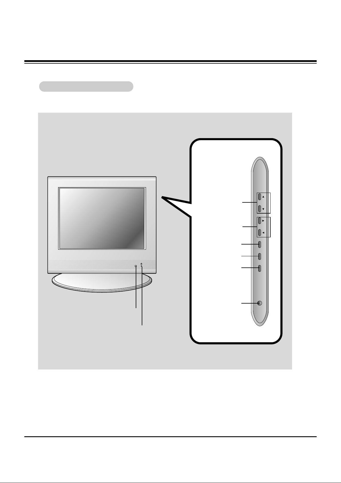
DESCRIPTION OF CONTROLS
Front of the
Front of the TVTV
Side Control Panel
Side Control Panel
TV/Video Button
Enter Button
Channel Buttons
On/Off Button
Menu Button
Volume Buttons
Remote Control Sensor
Power/Standby indicator
Illuminates brightly when the
TV is in standby mode. Dims
when the TV is switched on.
L15V24S
ch
vol
enter
menu
tv/video
on/off
Page 5
- 5 -
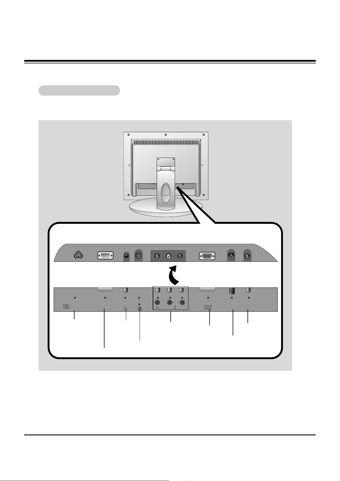
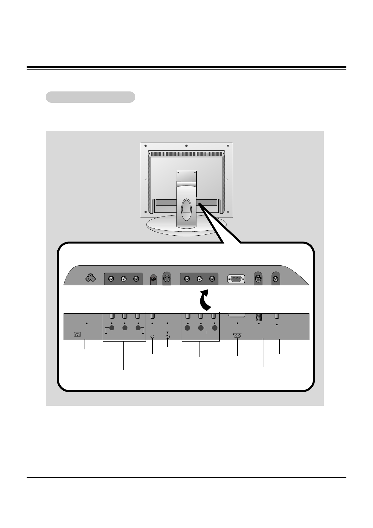
DESCRIPTION OF CONTROLS
Power Cord Socket
- This TV operates on
AC power. Never
attempt to operate the
TV on DC power.
Antenna Input
RS-232C Port
Headphone
Jack
Audio/Video
Input
S-Video Input
PC Input
PC Sound
Connection Panel
Connection Panel
Back of the
Back of the TVTV
RS-232CAC INPUT
H/P
S-VIDEO
VIDEO IN
RLVIDEO AUDIO(MONO)
PC INPUT ANT IN
+75 Ω
PC
SOUND(120V) INPUT
Page 6
- 6 -
DESCRIPTION OF CONTROLS
power
apc
menu
mute
sleep
ch
enter
vol vol
ch
cc
tv/video
0
2 3
5 64
8 97
1
mts
fcr
memory/erase
a.prog
flashbk dasp
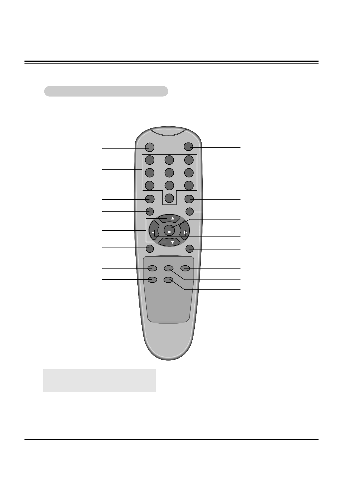
TV/VIDEO
CLOSED CAPTIONS
MUTE
ENTER
VOLUME (
F G
)
SLEEP
POWER
NUMBER
APC
MENU
MTS
FCR
AUTO PROGRAM
DASP
FLASHBK
MEMORY/ERASE
Remote Control Buttons
Remote Control Buttons
CHANNEL (
DE
)
l Press the FLASHBK button to view the last
program you were watching.
Page 7
- 7 -
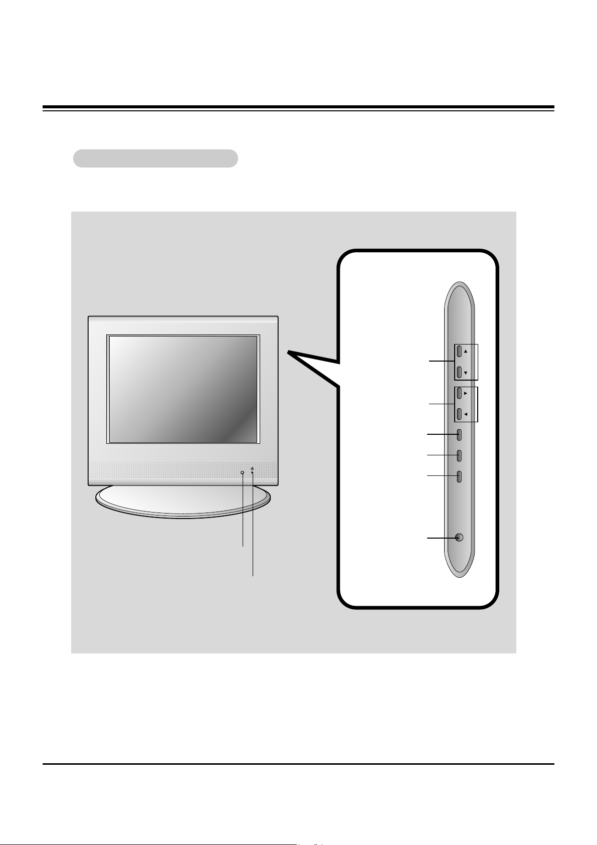
Front of the
Front of the TVTV
Side Control Panel
Side Control Panel
TV/Video Button
Enter Button
Channel Buttons
On/Off Button
Menu Button
Volume Buttons
Remote Control Sensor
Power/Standby indicator
Illuminates brightly when the
TV is in standby mode. Dims
when the TV is switched on.
L15V26C
DESCRIPTION OF CONTROLS
ch
vol
enter
menu
tv/video
on/off
Page 8
- 8 -
DESCRIPTION OF CONTROLS
Power Cord Socket
- This TV operates on
AC power. Never
attempt to operate the
TV on DC power.
Antenna Input
DVD/DTV IN
(Component (480i/480p,720p,1080i) Input
Headphone Jack
Audio/Video
Input
S-Video Input
PC Input
PC Sound
Connection Panel
Connection Panel
Back of the
Back of the TVTV
AC INPUT
Y
COMPONENT(480i/480p/720p/1080i)
DVD/DTV IN
H/P
P
R
P
B
S-VIDEO
VIDEO IN
RLVIDEO AUDIO(MONO)
ANT INPC INPUT
+75 Ω
PC
SOUND(120V)
Page 9

- 9 -
DESCRIPTION OF CONTROLS
power
apc
menu
mute
sleep
ch
enter
vol vol
ch
cc
tv/video
0
2 3
5 64
8 97
1
mts
fcr
memory/erase
a.prog
flashbk dasp
TV/VIDEO
CLOSED CAPTIONS
MUTE
ENTER
VOLUME (
F G
)
SLEEP TIMER
POWER
NUMBERS
APC
MENU
CHANNEL (
DE
)
MTS
FCR
AUTO PROGRAM
DASP
FLASHBK
MEMORY/ERASE
Remote Control Buttons
Remote Control Buttons
l Press the FLASHBK button to view the last
program you were watching.
Page 10

- 10 -
SPECIFICATIONS
Model L15V24S
Horizontal size (inches) 15.2
Height (inches) 14.5
Thickness (inches) 7
Weight (pounds) 16
Power requirements AC 120V, 60Hz
Television system NTSC
Television channels VHF : 2 ~ 13, UHF : 14 ~ 69
Cable : 1 ~ 125
Tube LCD Panel
Power consumption 45 W
External antenna impedance 75 Ω
Audio output 1 W + 1 W
Speaker outputs 8 Ω X 2
External input ports Power cord socket 1
RS-232C input port 1
S-VIDEO input 1
Headphone jack 1
Video/Audio input set 1
PC input jack 1
PC sound jack 1
Antenna input 1
Power supply cord set Standard North America three wire earth-grounding
with flexible cord SJT type or higher type.
CAUTION: If replacement becomes necessary, replace it with an exact duplicate.
Contact any Zenith authorized service center.
Page 11

Notes:
a. For optimum picture quality, use standard XGA (1024x768) computer output at a 60Hz refresh
rate. Using other formats (i.e.: VGA, SVGA, etc) or refresh rates may result in reduced picture
quality. (To change the computer video output format, please refer to the operating manual for the
computer you are using).
b. If the message “OUT OF RANGE” appears on the screen, adjust the PC output to a format listed in
the ‘Displayable Monitor Output Format Specifications' chart above.
c. The synchronization input form for Horizontal and Vertical frequencies is separate.
DPM (Display Power Management) mode
When the PC is in the power saving mode, the monitor automatically switches to DPM mode.
Displayable Monitor Output Format Specifications
VGA
SVGA
(MAC)
XGA
640x400
640x480
640x480
640x480
640x480
640x480
800x600
800x600
800x600
800x600
800x600
832x624
1024x768
1024x768
1024x768
37.9KHz
31.5KHz
35.0KHz
37.9KHz
37.5KHz
43.3KHz
35.2KHz
37.9KHz
48.1KHz
46.9KHz
53.7KHz
49.7KHz
48.4KHz
56.5KHz
60.2KHz
85Hz
60Hz
67Hz
72Hz
75Hz
85Hz
56Hz
60Hz
72Hz
75Hz
85Hz
75Hz
60Hz
70Hz
75Hz
MODE Resolution
Horizontal
Frequency (KHz)
Vertical
Frequency (Hz)
- 11 -
SPECIFICATIONS
Displayable Monitor Output Format Specifications
Page 12

- 12 -
SPECIFICATIONS
Model L15V26C
Horizontal size (inches) 15.2
Height (inches) 14.5
Depth (inches) 7
Weight (pounds) 16
Power requirements AC 120V, 60Hz
Television system NTSC
Television channels VHF : 2 ~ 13, UHF : 14 ~ 69
Cable : 1 ~ 125
Tube LCD Panel
Power consumption 45 W
External antenna impedance 75 Ω
Audio output 1 W + 1 W
Speaker outputs 8 Ω X 2
External input ports Power cord socket 1
Component (480i/480p/720p/1080i) input 1 set
S-VIDEO input 1
Headphone jack 1
Video/Audio input set 1
PC input jack 1
PC sound jack 1
Antenna input 1
Power supply cord set Standard North America three wire earth-grounding
with flexible cord SJT type or higher type.
CAUTION: If replacement becomes necessary, replace it with an exact duplicate.
Contact any Zenith authorized service center.
Page 13

Notes:
a. For optimum picture quality, use standard XGA (1024x768) computer output at a 60Hz refresh
rate. Using other formats (i.e.: VGA, SVGA, etc) or refresh rates may result in reduced picture
quality. (To change the computer video output format, please refer to the operating manual for the
computer you are using).
b. If the message “
OUT OF RANGE” appears on the screen, adjust the PC output to a format listed in
the ‘Displayable Monitor Output Format Specifications' chart above.
c. The synchronization input form for Horizontal and Vertical frequencies is separate.
DPM (Display Power Management) mode
When the PC is in the power saving mode, the monitor automatically switches to DPM mode.
Displayable Monitor Output Format Specifications
VGA
SVGA
(MAC)
XGA
640x400
640x480
640x480
640x480
640x480
640x480
800x600
800x600
800x600
800x600
800x600
832x624
1024x768
1024x768
1024x768
37.9KHz
31.5KHz
35.0KHz
37.9KHz
37.5KHz
43.3KHz
35.2KHz
37.9KHz
48.1KHz
46.9KHz
53.7KHz
49.7KHz
48.4KHz
56.5KHz
60.2KHz
85Hz
60Hz
67Hz
72Hz
75Hz
85Hz
56Hz
60Hz
72Hz
75Hz
85Hz
75Hz
60Hz
70Hz
75Hz
MODE Resolution
Horizontal
Frequency (KHz)
Vertical
Frequency (Hz)
- 13 -
SPECIFICATIONS
Displayable Monitor Output Format Specifications
Page 14

- 14 -
ADJUSTMENT INSTRUCTION
1. Application Object
This instruction is for the application to the LCD TV/Monitor,
ML-024A.
2. Notes
(1) This LCD TV has power within set. Connect the power
correctly, then start the adjustment.
(2) The adjustment must be performed under the correct
sequence.
(3) The adjustment must be performed in the circumstance of
25
!5cC of temperature and 65!10% of relative humidity if
there is no specific designation.
(4) The input voltage of the receiver must keep 100~220V,
50/60Hz in adjusting.
(5) The set must be operated for 15 minutes preliminarily
before adjustment if there is no specific designation.
O ‘Heat Run’ must be performed with the full white signal or TV
noise signal in the internal part of the set.
O The time for ‘Heat Run’ can be changed owing to production
plan.
O Condition of Line Test : Standard color signal - 65!1dBuV
3. PC Mode Adjustment
3-1. Required Test Equipment
(1) Window Pattern which satisfied with VESA Spec. or
pattern which has White-Black signal simultaneously.
(2) Remote control for adjustment
3-2. Preparation for Adjustment
(1) Perform ‘Heat Run’ for more than 15 minutes in white
pattern.
(2) Connect the signal of pattern generator with LCD TV of PC
Input Jack(D-Sub).
(3) Confirm the XGA(1024x768) Window Pattern or
signal(White-Black) using the 801-GF/GD, VG819.
(4) Use the IN-START Key on R/C for adjustment to enter the
PC adjustment mode.
(5) Example of adjustment screen.
(6) Enter into the adjustment mode as <Fig. 1> and select the
cursor(red letters) to “RGBSE G” with the channel key on
R/C for adjustment.
(7) Press the Volume G on R/C for adjustment.
(8) At this time the adjustment starts automatically changing
the number in order of RO --> GO --> BO --> RD --> GD --
> BD.
Finally, when the number of BD is changed the adjustment
is completed.
(9) Press the MENU or EXIT key to come out of the
adjustment mode.
4. Option
No.
1
2
3
4
5
6
COMPO
3SYS
LGCON
MPIOS
BLUEB
RLOCK
0
0
0
0
1
0
Component input mode
0 : not ready 1 : ready
Video input applicable system
0 : NTSC-M(North America)
1 : NTSC-M & PAL-M/N multi(South America)
RS232C Protocol
0 : MPI Protocol(Zenith program)
1 : LG Protocol(LG program)
RS232C Protocol OSD display
0 : non display OSD 1 : display OSD
No - signal Video mode
0 : Black-Back 1 : Blue-Back
RS232C Protocol
0 : Remocon Lock 1: Remocon Unlock
Item Specification Remark
<Fig. 1>
Page 15

- 15 -
ADJUSTMENT INSTRUCTION
5. RS232C(RMS Only)
(1) Use the Untweasted 232C Cable
(2) Use the PC program which is sent by Zenith
(3) 232C Protocol
No.
1
2
3
4
5
6
7
8
9
10
Power On
Power Off
Volume Up
Volume Down
Volume Direct Access
Set Volume Limit
Direct Channel
Select
Poll/Front Panel
Lockout
Poll/Front Panel
Unlockout
Status Read Back
E110F1
E111F2
E10AEB
E10BEC
EAXXYY
EBXXYY
E4XXYY
A0A0
B0B0
ABWWXXYY
Turn the set on.
Turn the set off.
Volume up 1 level
Volume down 1 level
Select desired volume data directly.
XX : desired volume value(HEX)
YY : check Sum of EA and XX
Set the range of adjustable volume value
XX : adjustment data of volume value
YY : check Sum of E1 and XX
Select channel with number keys.
E4 : Direct Channel command
XX : channel data want to change
YY : check Sum of E4 and XX
Front/Remocon Key Lock command
A0 : Key Lock command(Both Local and Remocon keys)
A0 ; Check Sum
Front/Remocon Key Lock command
B0 : Key Unlock command(Both Local and Remocon keys)
B0 : Check Sum
Read present status of set
Data Bytel(XX)
Bit Description
0~5 Volume data(hex. 0~3F)
6 signal status(1=Good, 0=Bad)
7 Power status(1=On, 0=Off)
Data Byte2(YY)
Bit Description
0~7 Channel Number
(Same with direct Channel)
Command Remark
Page 16

- 16 -
BLOCK DIAGRAM
Page 17

- 17 -
NOTES
Page 18

- 18 -
EXPLODED VIEW
300
120
112
520
521
400
410
530
310
560
330
Page 19

- 19 -
EXPLODED VIEW PARTS LIST
112 6304FLP006C 6304FLP006C LCD MODULE,LC151X01-C3M2 LG PHILPS TFT COLOR NON
120 6400VA0017A 6400VA0017A SPEAKER,GENERAL T401SX-095K14 LG C&D 8 OHM 1.0/1.5W
300 3091V00443A 3091V00443B CABINET ASSEMBLY
310 5020V00552K 5020V00552J BUTTON,CONTROL 7KEY
330 5020V00553H 5020V00553G BUTTON,POWER 1KEY
400 3809V00300A 3809V00300B BACK COVER ASSEMBLY
410 4811V00029A 4811V00029C BRACKET ASSEMBLY,MAIN
520 6871VMMB86A 6871VMMN53A PCB ASSEMBLY,MAIN ML-024A RMS
521 4950V00101A 4950V00101A METAL,MAIN FRAME METAL RN-15LA50
530 6871VSMA12A 6871VSMA12A PCB ASSEMBLY,SUB CONT
560 6871VSMN38A 6871VSMN38B PCB ASSEMBLY,SUB PSW ML024A POWER
No.
Part No.
L15V24S L15V26C
Description
Page 20

- 20 -
REPLACEMENT PARTS LIST
LOCA. NO PART NO DESCRIPTION
Q202
Q351
Q353
Q403
Q406
Q502
Q51
Q510
Q52
Q53
Q55
Q56
Q57
Q651
Q701
Q702
Q703
Q704
Q705
Q801
Q802
D100
D51
D52
D53
D54
D55
D56
D57
D601
D602
D701
D702
D703
D703
D704
D706
D707
D709
LED1
ZD202
ZD203
ZD400
ZD701
0TR387500AA
0TR150400BA
0TR150400BA
0TR150400BA
0TR387500AA
0TR150400BA
0TRKE80021A
0TR150400BA
0TRKE80021A
0TFVI80034A
0TR387500AA
0TR387500AA
0TR387500AA
0TR150400BA
0TR387500AA
0TR150400BA
0TR387500AA
0TFFC10007A
0TR387500AA
0TR387500AA
0TR150400BA
0DD181009AB
0DD181009AB
0DD181009AB
0DD181009AB
0DD181009AB
0DRDI00028B
0DRDI00028B
0DD181009AB
0DD181009AB
0DD181009AB
0DB260000AA
0DD100009AM
0DD140009AA
0DR060009AA
0DD100009AM
0DR060009AA
0DRSD00091A
0DRSD00091A
0DL200000CA
0DZRM00178A
0DZRM00178A
0DZ330009BA
0DZ180009AG
CHIP 2SC3875S(ALY) KEC
CHIP 2SA1504S(ASY) KEC
CHIP 2SA1504S(ASY) KEC
CHIP 2SA1504S(ASY) KEC
CHIP 2SC3875S(ALY) KEC
CHIP 2SA1504S(ASY) KEC
KTC5103D KEC R/TP DPAK 60V 5A
CHIP 2SA1504S(ASY) KEC
KTC5103D KEC R/TP DPAK 60V 5A
SUD45P0315 VISHAY R/TP TO252 30V 13A
CHIP 2SC3875S(ALY) KEC
CHIP 2SC3875S(ALY) KEC
CHIP 2SC3875S(ALY) KEC
CHIP 2SA1504S(ASY) KEC
CHIP 2SC3875S(ALY) KEC
CHIP 2SA1504S(ASY) KEC
CHIP 2SC3875S(ALY) KEC
FQPF12N60 FAIRCHILD ST TO220 600V 10.5A
CHIP 2SC3875S(ALY) KEC
CHIP 2SC3875S(ALY) KEC
CHIP 2SA1504S(ASY) KEC
KDS181 TP KEC 85V 300MA
KDS181 TP KEC 85V 300MA
KDS181 TP KEC 85V 300MA
KDS181 TP KEC 85V 300MA
KDS181 TP KEC 85V 300MA
B350A DIODES R/TP SMA 35V 3A
B350A DIODES R/TP SMA 35V 3A
KDS181 TP KEC 85V 300MA
KDS181 TP KEC 85V 300MA
KDS181 TP KEC 85V 300MA
G2SBA60 BK G.I 600V 1.5A 60A 5UA
EU1ZV(1) TP SANKEN
EK14 V(1) TP SANKEN E/EOTMD 40V
TVR06J DO41 600V 0.6A
EU1ZV(1) TP SANKEN
TVR06J DO41 600V 0.6A
SF20JC10 100V 20A 200A .SEC 0.7MA
SF20JC10 100V 20A 200A .SEC 0.7MA
LED,SAM5670(DL2LRG) BK YGREEN
ZENERS,UDZS TE17 5.1B
ZENERS,UDZS TE17 5.1B
ZENER,HZT33(TP) HITACHI
ZENERS,MTZJ18B
LOCA. NO PART NO DESCRIPTION
IC1
IC100
IC101
IC102
IC301
IC351
IC352
IC501
IC502
IC51
IC52
IC53
IC601
IC602
IC603
IC604
IC701
IC702
IC703
IC704
IC707
IC707
IC708
IC709
IC710
IC801
IC901
IC902
PC1
PC2
Q101
Q102
Q54
IC2
IC705
IC706
Q1
Q100
Q1101
Q1102
Q1103
Q200
Q201
0IMCRTH001A
0IZZVC0037A
0IAL241610B
0IFA752700A
0IMCRMI006A
0IMCRFA010A
0ISO204000A
0IMCRTW001A
0ICTMMO004A
0ITK118100B
0IMCRRH005A
0IMCRRH005A
0IMCRMN014A
0ISA428200A
0IKE704200J
0IMCRFA009A
0IMCRFA017A
0IMCRFA007A
0IMCRFA016A
0IKE780500P
0IMCRFA016A
0IMCRKE006B
0IKE780500Q
0IKE780500Q
0IKE780500Q
0IMCRAD002A
0IAL242110A
0IDS232000A
0ILI817000G
0ILI817000G
0IFA270000A
0IFA270000A
0IMCRRH004A
0TF492509AA
0TF492509AA
0TF492509AA
0TR387500AA
0TR387500AA
0TR387500AA
0TR387500AA
0TR387500AA
0TR387500AA
0TR387500AA
THC63LVDM83R 56P
SDA555X 52P ST UMICOM
AT24C16A10PI2.7 8PIN DIP
KA75270Z 3 TP RESET IC
M52758FP 36PIN
KA7809R, FAIRCHILD 2P
32P,QFP BK IIC BUS VIDEO S/W
LG8801 TECHWELL 160PQFP
SC786108DWR2 16 R/TP OSD
TK11840L 8P SOT23L
UM6K1N ROHM 6P SOT363
UM6K1N ROHM 6P SOT363
MSP3440G QA B8 V3
LA4282 12S AUDIO AMP
KIA7042AF SOT89 TP 4.2V
KA78M08RTM, FAIRCHILD 2P
KA3883C FAIRCHILD 8 SOP
KA431Z FAIRCHILD 3DIP
KA78RH33 FAIRCHILD 2P
KIA78L05BP(AT) 3P 5V,150MA
KA78RH33 FAIRCHILD 2P
KIA278R33PI KEC TO220IS 4P
KIA7805API 3P TO220
KIA7805API 3P TO220
KIA7805API 3P TO220
AD9883A ANALOG DEVICE 80P
AT24C2110SI2.5 8P,SOP TP 1K EEPROM
DS232AS 16P,SOP TP RS232
LTV817MVB 4P,DIP BK PHOTO COU
LTV817MVB 4P,DIP BK PHOTO COU
2N7000TA TO92, 3P
2N7000TA TO92, 3P
UMY1N ROHM 5P SOT353
FET,SI4925DY TP TEMIC 30V 6.1A SO8
FET,SI4925DY TP TEMIC 30V 6.1A SO8
FET,SI4925DY TP TEMIC 30V 6.1A SO8
CHIP 2SC3875S(ALY) KEC
CHIP 2SC3875S(ALY) KEC
CHIP 2SC3875S(ALY) KEC
CHIP 2SC3875S(ALY) KEC
CHIP 2SC3875S(ALY) KEC
CHIP 2SC3875S(ALY) KEC
CHIP 2SC3875S(ALY) KEC
IC
TRANSISTOR
RUN DATE : 2002.11.22
For Capacitor & Resistors, the
charactors at 2nd and 3rd digit
in the P/No. means as follows;
CC, CX, CK, CN : Ceramic
CQ : Polyestor
CE : Electrolytic
RD : Carbon Film
RS : Metal Oxide Film
RN : Metal Film
RF : Fusible
DIODE
Page 21

- 21 -
LOCA. NO PART NO DESCRIPTION
ZD702
ZD703
C10
C101
C113
C128
C13
C209
C211
C215
C216
C289
C302
C315
C317
C331
C351
C353
C353
C354
C356
C357
C362
C364
C380
C381
C403
C404
C408
C412
C499
C501
C51
C523
C526
C541
C547
C55
C581
C60
C601
C602
C605
C613
C614
C616
C617
0DZ150009AD
0DZ820009AH
0CE227DF618
0CE107BF618
0CE107BF618
0CE227BH618
0CE227DF618
0CE476DF618
0CE106DF618
0CE106DF618
0CE106DF618
0CE104DK618
0CE476DF618
0CE476DF618
0CE476DF618
0CE107DF618
0CE227DF618
0CE475DK618
0CE106DF618
0CE476DF618
0CE106DF618
0CE106DF618
0CE107DF618
0CE336DF618
0CE105DK618
0CE106DF618
0CE476DH618
0CE108DD618
0CE106DK618
0CE105DK618
0CE476DF618
0CE107DF618
0CF2241N5AA
0CE104DK618
0CE107DF618
0CE107DF618
0CE104DK618
0CF2241N5AA
0CE107DF618
0CK105DF64A
0CE477BF618
0CE477BF618
0CE107BF618
0CE106DF618
0CE106DF618
0CE107DF618
0CE107BF618
ZENERS,MTZJ15B
ZENERS,MTZJ8.2B
220UF STD 16V M FL TP5
100UF KME 16V M FL TP5
100UF KME 16V M FL TP5
220UF KME 25V M FL TP5
220UF STD 16V M FL TP5
47UF STD 16V M FL TP5
10UF STD 16V M FL TP5
10UF STD 16V M FL TP5
10UF STD 16V M FL TP5
0.1000UF STD 50V M
47UF STD 16V M FL TP5
47UF STD 16V M FL TP5
47UF STD 16V M FL TP5
100UF STD 16V M FL TP5
220UF STD 16V M FL TP5
4.7UF STD 50V 20% FL TP 5
10UF STD 16V M FL TP5
47UF STD 16V M FL TP5
10UF STD 16V M FL TP5
10UF STD 16V M FL TP5
100UF STD 16V M FL TP5
33UF STD 16V M FL TP5
1UF STD 50V M FL TP5
10UF STD 16V M FL TP5
47UF STD 25V 20% FL TP 5
1000UF STD 10V M FL TP5
10UF STD 50V M FL TP5
1UF STD 50V M FL TP5
47UF STD 16V M FL TP5
100UF STD 16V M FL TP5
0.22UF D 100V 10%
0.1000UF STD 50V M FL TP5
100UF STD 16V M FL TP5
100UF STD 16V M FL TP5
0.1000UF STD 50V M FL TP5
0.22UF D 100V 10%
100UF STD 16V M FL TP5
1UF 2012 16V 20% R/TP F(Y5V)
470UF KME 16V M FL TP5
470UF KME 16V M FL TP5
100UF KME 16V M FL TP5
10UF STD 16V M FL TP5
10UF STD 16V M FL TP5
100UF STD 16V M FL TP5
100UF KME 16V M FL TP5
LOCA. NO PART NO DESCRIPTION
C62
C620
C621
C626
C627
C629
C633
C643
C646
C647
C647
C648
C649
C651
C652
C652
C654
C67
C69
C698
C699
C700
C701
C702
C703
C704
C706
C706
C707
C708
C709
C717
C718
C719
C720
C721
C722
C723
C725
C726
C730
C731
C732
C733
C734
C735
C736
C777
C799
0CK105DF64A
0CE335DK618
0CE107BF618
0CK224DF56A
0CK224DF56A
0CE107DF618
0CE107DF618
0CE476BF618
0CE225DK618
0CE225BK618
0CE225DK618
0CQ1031N509
0CQ1031N509
0CE107BH618
0CE107BF618
0CE107DF618
0CE476BF618
0CE337ZF638
0CE107BH618
0CK224DF56A
0CK224DF56A
181-091D
0CQZVBK002C
0CQZVBK002A
181-120N
181-120N
0CE476BK618
0CE4772J618
0CE1272U610
181-091D
181-091U
181-091D
181-091D
0CE227DK618
181-091D
0CE4772J618
0CE477BF618
0CE477BF618
0CE4772J618
0CE477BF618
0CE4772J618
0CE477BF618
0CE4772J618
181-120K
0CE4772J618
0CE477BF618
0CE4772J618
181-091D
0CE107BF618
1UF 2012 16V 20%
3.3UF STD 50V 20% FL TP 5
100UF KME 16V M FL TP5
220000PF 2012 16V 10%
220000PF 2012 16V 10%
100UF STD 16V M FL TP5
100UF STD 16V M FL TP5
47UF KME TYPE 16V 20%
2.2UF STD 50V 20% FL TP 5
2.2UF KME TYPE 50V 20%
2.2UF STD 50V 20%
0.01U 100V K
0.01U 100V K POLY TP
100UF KME 25V M FL TP5
100UF KME 16V M FL TP5
100UF STD 16V M FL TP5
47UF KME TYPE 16V 20%
330UF SEP 16V 20%
100UF KME 25V M
220000PF 2012 16V 10%
220000PF 2012 16V 10%
DEHR33A102KN2A 1000PF 1KV 10%,10%
A.C 275V 0.22UF K (S=22.5)
A.C 275V 0.1UF M (S=15)
1000PF 4KV M E
1000PF 4KV M E
47UF KME 50V M FL TP5
470UF KMF 35V 20%
120UF KMF 400V 20%
DEHR33A102KN2A 1000PF 1KV 10%,10%
R 220PF 2KV 10%,10%
DEHR33A102KN2A 1000PF 1KV 10%,10%
DEHR33A102KN2A 1000PF 1KV 10%,10%
220UF STD 50V M FL TP5
DEHR33A102KN2A 1000PF 1KV 10%,10%
470UF KMF 35V 20%
470UF KME 16V M
470UF KME 16V M
470UF KMF 35V 20%
470UF KME 16V M FL TP5
470UF KMF 35V 20%
470UF KME 16V M FL TP5
470UF KMF 35V 20% TP 5 FL
2200PF 4KV M E FMTW LEAD 4.5
470UF KMF 35V 20% TP 5 FL
470UF KME 16V M FL TP5
470UF KMF 35V 20% TP 5 FL
DEHR33A102KN2A 1000PF 1KV 10%,10%
100UF KME 16V M FL TP5
REPLACEMENT PARTS LIST
CAPACITOR
Page 22

- 22 -
LOCA. NO PART NO DESCRIPTION
C810
C832
C970
F701
JA201
RJ201
RJ202
L401
L51
L52
T51
T52
T701
F704
FR704
L502
L503
L504
L505
L506
L507
L518
R200
R201
R51
R54
R69
R70
R701
R702
R703
R704
R705
R707
R71
R711
R712
R715
R727
R728
SW1101
0CK823DK56A
0CE107DF618
0CE476DD618
0FT3151B51B
6612VCH003B
6613V00008F
6612VJH008D
0LA0272K139
6140VR0004A
6140VR0004A
6170VH0001A
6170VH0001A
6170VMCA47A
0RP0020J809
0RP0020J809
0RRZVTA001A
0RRZVTA001A
0RRZVTA001A
0RRZVTA001A
0RRZVTA001A
0RRZVTA001A
0RRZVTA001A
0RD1000H609
0RD1000H609
0RS6800J607
0RS6800J607
0RN1302F409
0RN4701F409
0RS5602K619
0RKZVTA001C
0RKZVTA001K
0RS5602K619
0RS5602K619
0RD3303H609
0RN4701F409
0RS5602K619
0RD6803H609
180-A01R
0RD0472H609
0RD0472H609
140-313A
82000PF 2012 50V 10%
100UF STD 16V M FL TP5
47UF STD 10V 20% FL TP 5
FUSE,SLOW BLOW 3150MA 250V
JACK,PHONE H=6.5 STEREO 1P W/O S/W WHITE
JACK ASSY,E/P(ST)+SVHS+3P H6.5 GOLD COLOR
JACK,RCAPJ6063D DVD IN 3P
INDUCTOR,27UH K
COIL,ENERGY RECOVERY TOKO
COIL,ENERGY RECOVERY TOKO
TRANSFORMER,INVERTER 969HGK003 8.985UH
TRANSFORMER,INVERTER 969HGK003 8.985UH
TRANSFORMER,SMPS[COIL] EER3016 510UH
0.02 OHM 1 W 20% TA52
0.02 OHM 1 W 20% TA52
MNR14E0AJ101 R OHM 100 OHM 5%
MNR14E0AJ101 R OHM 100 OHM 5%
MNR14E0AJ101 R OHM 100 OHM 5%
MNR14E0AJ101 R OHM 100 OHM 5%
MNR14E0AJ101 R OHM 100 OHM 5%
MNR14E0AJ101 R OHM 100 OHM 5%
MNR14E0AJ101 R OHM 100 OHM 5%
100 OHM 1/2 W 5.00% TA52
100 OHM 1/2 W 5.00% TA52
680 OHM 1 W 5.00% TA62
680 OHM 1 W 5.00% TA62
13K OHM 1/6 W 1.00% TA52
4.7K OHM 1/6 W 1.00% TA52
56K OHM 2 W 5.00% TR
8.2M OHM 1/2 W 5%
0.47M OHM 1/2 W 5%
56K OHM 2 W 5.00% TR
56K OHM 2 W 5.00% TR
330K OHM 1/2 W 5.00% TA52
4.7K OHM 1/6 W 1.00% TA52
56K OHM 2 W 5.00% TR
680K OHM 1/2 W 5.00% TA52
2 W RW ROUND G 0.39 TA31(63)
47 OHM 1/2 W 5.00% TA52
47 OHM 1/2 W 5.00% TA52
SWITCH,TACT 2LEAD 100G(TA)
LOCA. NO PART NO DESCRIPTION
SW1101
SW1102
SW1103
SW1104
SW1105
SW1106
SW1107
L1
L1
L101
L102
L119
L199
L200
L201
L202
L204
L205
L206
L213
L214
L298
L299
L313
L351
L400
L402
L501
L501
L502
L503
L504
L505
L506
L507
L515
L516
L517
L580
L600
L601
L602
L603
L801
L802
L803
L99
140-275B
140-313A
140-313A
140-313A
140-313A
140-313A
140-313A
6210TCE001G
6210TCE001G
6210TCE001G
6210TCE001G
6210TCE001A
6210TCE001G
6210TCE001A
6210TCE001A
6210TCE001A
6210TCE001A
6210TCE001A
6210TCE001G
6210TCE001G
6210TCE001G
6210TCE001A
6210TCE001A
6210TCE001G
6210TCE001G
6210TCE001G
6210TCE001G
6210TCE001G
6210TCE001G
6210VC0004A
6210VC0004A
6210VC0004A
6210VC0004A
6210VC0004A
6210VC0004A
6210TCE001G
6210VC0004A
6210TCE001G
6210TCE001A
6210TCE001G
6210TCE001G
6210TCE001G
6210TCE001G
6210TCE001G
6210TCE001G
6210TCE001G
6210TCE001G
SWITCH,PUSH JDPB21NA 30V 0.3A
SWITCH,TACT 2LEAD 100G(TA) 5V 0.001A
SWITCH,TACT 2LEAD 100G(TA) 5V 0.001A
SWITCH,TACT 2LEAD 100G(TA) 5V 0.001A
SWITCH,TACT 2LEAD 100G(TA) 5V 0.001A
SWITCH,TACT 2LEAD 100G(TA) 5V 0.001A
SWITCH,TACT 2LEAD 100G(TA) 5V 0.001A
FILTER,EMC HH1M3216501
FILTER,EMC HH1M3216501
FILTER,EMC HH1M3216501
FILTER,EMC HH1M3216501
FILTER,EMC HB1S2012080JT
FILTER,EMC HH1M3216501
FILTER,EMC HB1S2012080JT
FILTER,EMC HB1S2012080JT
FILTER,EMC HB1S2012080JT
FILTER,EMC HB1S2012080JT
FILTER,EMC HB1S2012080JT
FILTER,EMC HH1M3216501
FILTER,EMC HH1M3216501
FILTER,EMC HH1M3216501
FILTER,EMC HB1S2012080JT
FILTER,EMC HB1S2012080JT
FILTER,EMC HH1M3216501
FILTER,EMC HH1M3216501
FILTER,EMC HH1M3216501
FILTER,EMC HH1M3216501
FILTER,EMC HH1M3216501
FILTER,EMC HH1M3216501
FILTER,EMC BK3216 4S600
FILTER,EMC BK3216 4S600
FILTER,EMC BK3216 4S600
FILTER,EMC BK3216 4S600
FILTER,EMC BK3216 4S600
FILTER,EMC BK3216 4S600
FILTER,EMC HH1M3216501
FILTER,EMC BK3216 4S600
FILTER,EMC HH1M3216501
FILTER,EMC HB1S2012080JT
FILTER,EMC HH1M3216501
FILTER,EMC HH1M3216501
FILTER,EMC HH1M3216501
FILTER,EMC HH1M3216501
FILTER,EMC HH1M3216501
FILTER,EMC HH1M3216501
FILTER,EMC HH1M3216501
FILTER,EMC HH1M3216501
SWITCH
FILTER & CRYSTAL
REPLACEMENT PARTS LIST
FUSE & JACK
COIL & TRANSFORMER
RESISTOR
Page 23

- 23 -
REPLACEMENT PARTS LIST
LOCA. NO PART NO DESCRIPTION
LF701
LF702
Z100
Z500
Z600
P1101
P1102
P401A
P701
P900
P901
PA1101
TH701
TU401
VA701
A1
“
A2
A3
A4
A5
6200JB8008N
6200JB8008N
156-A01L
156-A02X
156-A02M
6631V20014E
387-A07B
6700VNF019E
6620VZ0002A
6630G15E215
6630GZ00509
6726VV0006D
163-048D
6700VNF019E
164-003K
3828VA0359A
3828VA0359B
6710V00082M
6410VUH007A
6851V00004D
6866VA9001A
FILTER,EMC SMC BK OR 14*7*7.5H, 38MH
FILTER,EMC SMC BK OR 14*7*7.5H, 38MH
RESONATOR,CRYSTAL HC49U 6.000MHZ 30PPM
RESONATOR,CRYSTAL HC49U 27.000MHZ 25PPM
RESONATOR,CRYSTAL HC49U 18.432MHZ 30PPM
CONNECTOR ASSEMBLY,12P 2.0MM
CONNECTOR ASSEMBLY,7P 2.5MM
TUNER,TAFHH001P LG NTSC FS
SOCKET ,DRAWING IS7007 ISHENG AC SOCKET
CONNECTOR ,DSUB KSD 15P 2.29MM KCNDS30054
CONNECTOR ,DSUB KSD 9P SPECIAL FEMALE
REMOTE CONTROLLER RECEIVER,38.0KHZ
THERMISTOR,KL15L2R5 +/ 15% 125V
TUNER,TAFHH001P LG NTSC FS
VARISTOR,SVC621D14A 620V 0%
MANUAL,OWNERS ML024A RU15LA51 ZENITH EN
MANUAL,OWNERS ML024A RU15LA50 ZENITH EN
REMOTE CONTROLLER,ML024A W/O TXT
POWER CORD,SP305+IS034 SVT18AWG*3C
CABLE ASSEMBLY,AUDIO TO AUDIO
CONNECTOR ,DSUB 29909C,AT,L1830
LOCA. NO PART NO DESCRIPTION
MISCELLANEOUS
ACCESSORIES
Page 24

Page 25

Page 26

MAIN(TOP) MAIN(BOTTOM)
CONTROL POWER
 Loading...