

Zenith L17V36DVD Installation Manual

Operating Guide | Warranty
Model Number | L17W36DVD | LCD TV
© Copyright 2003, Zenith Electronics Corporation.
Warning
CAUTION
RISK OF ELECTRIC SHOCK
DO NOT OPEN
W
arning
W
arning
WARNING:
TO REDUCE THE RISK OF ELECTRIC SHOCK DO NOT REMOVE COVER (OR BACK). NO USER
SERVICEABLE PARTS INSIDE. REFER TO QUALIFIED SERVICE PERSONNEL.
The lightning flash with arrowhead symbol, within an equilateral triangle, is intended to alert the user to
the presence of uninsulated “dangerous voltage” within the product’s enclosure that may be of sufficient magnitude to constitute a risk of electric shock to persons.
The exclamation point within an equilateral triangle is intended to alert the user to the presence of
important operating and maintenance (servicing) instructions in the literature accompanying the appliance.
WARNING:
TO PREVENT FIRE OR SHOCK HAZARDS, DO NOT EXPOSE THIS PRODUCT TO RAIN OR MOISTURE.
NOTE TO CABLE/TV INSTALLER:
This reminder is provided to call the CATV system installer’s attention to Article 820-40 of the National Electric
Code (U.S.A.). The code provides guidelines for proper grounding and, in particular, specifies that the cable
ground shall be connected to the grounding system of the building, as close to the point of the cable entry as practical.
REGULATORY INFORMATION
This equipment has been tested and found to comply with the limits for a Class B digital device, pursuant to Part
15 of the FCC Rules. These limits are designed to provide reasonable protection against harmful interference in
a residential installation. This equipment generates, uses and can radiate radio frequency energy and, if not
installed and used in accordance with the instructions, may cause harmful interference to radio communications.
However, there is no guarantee that interference will not occur in a particular installation. If this equipment does
cause harmful interference to radio or television reception, which can be determined by turning the equipment off
and on, the user is encouraged to try to correct the interference by one or more of the following measures:
- Reorient or relocate the receiving antenna.
- Increase the separation between the equipment and receiver.
- Connect the equipment into an outlet on a circuit different from that to which the receiver is connected.
- Consult the dealer or an experienced radio/TV technician for help.
Any changes or modifications not expressly approved by the party responsible for compliance could void the
user’s authority to operate the equipment.
CAUTION:
Do not attempt to modify this product in any way without written authorization from Zenith Electronics
Corporation. Unauthorized modification could void the user’s authority to operate this product.
COMPLIANCE:
The responsible party for this product’s compliance is:
Zenith Electronics Corporation
2000 Millbrook Drive
Lincolnshire, Il 60069, USA
Phone: 1-847-941-8000
2
Safety Instructions
PORTABLE CART WARNING
Safety Instructions
Safety Instructions
Important safeguards for you and your new product
Y our product has been manufactured and tested with your safety in mind. However, improper use can result in potential electrical shock or fire hazards. To avoid defeating the safeguards that have been built into your new product, please read and
observe the following safety points when installing and using your new product, and save them for future reference.
Observing the simple precautions discussed in this manual can help you get many years of enjoyment and safe operation
that are built into your new product.
This product complies with all applicable U.S. Federal safety requirements, and those of the Canadian Standards
Association.
1. Read Instructions
All the safety and operating instructions should be read
before the product is operated.
2. Follow Instructions
All operating and use instructions should be followed.
3. Retain Instructions
The safety and operating instructions should be retained for
future reference.
4. Heed Warnings
All warnings on the product and in the operating instructions
should be adhered to.
5. Cleaning
Unplug this product from the wall outlet before cleaning. Do
not use liquid cleaners or aerosol cleaners. Use a damp
cloth for cleaning.
6. Water and Moisture
Do not use this product near water, for example, near a bath
tub, wash bowl, kitchen sink, or laundry tub, in a wet basement, or near a swimming pool.
7. Accessories, Carts, and Stands
Do not place this product on a slippery or tilted surface, or on
an unstable cart, stand, tripod, bracket, or table. The product
may slide or fall, causing serious injury to a child or adult,
and serious damage to the product. Use only with a cart,
stand, tripod, bracket, or table recommended by the manufacturer, or sold with the product. Any mounting of the product should follow the manufacturer’s instructions, and should
use a mounting accessory recommended by the manufacturer.
8. Transporting Product
A product and cart combination should be moved with care.
Quick stops, excessive force, and uneven surfaces may
cause the product and cart combination to overturn.
9. Attachments
Do not use attachments not recommended by the product
manufacturer as they may cause hazards.
10. Ventilation
Slots and openings in the cabinet are provided for ventilation
and to ensure reliable operation of the product and to protect
it from overheating, and these openings must not be blocked
or covered. The openings should never be blocked by placing the product on a bed, sofa, rug, or other similar surface.
This product should not be placed in a built-in installation
such as a bookcase or rack unless proper ventilation is provided or the manufacturer’s instructions have been adhered
to.
11. Power Sources
This product should be operated only from the type of power
source indicated on the marking label. If you are not sure of
the type of power supply to your home, consult your product
dealer or local power company. For products intended to
operate from battery power, or other sources, refer to the
operating instructions.
12. Power-Cord Polarization
This product is equipped with a three-wire grounding type
plug, a plug having a third (grounding) pin. This plug will only
fit into the grounding-type power outlet. This is a safety feature. If you are unable to insert the plug into the outlet, contact your electrician to replace your obsolete outlet. Do not
defeat the safety purpose of the grounding-type plug.
13. Power-Cord Protection
Power-supply cords should be routed so that they are not
likely to be walked on or pinched by items placed upon or
against them, paying particular attention to cords at plugs,
convenience receptacles, and the point where they exit from
the product.
3
Safety Instructions
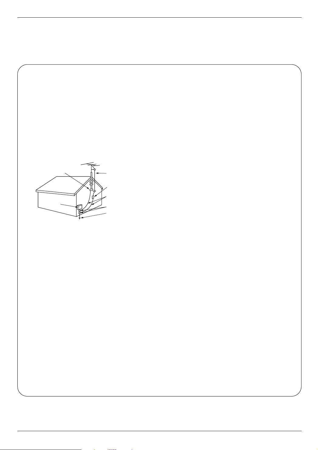
Antenna Lead in Wire
Antenna Discharge Unit
(NEC Section 810-20)
Grounding Conductor
(NEC Section 810-21)
Ground Clamps
Power Service Grounding
Electrode System (NEC
Art 250, Part H)
Ground Clamp
Electric Service
Equipment
Safety Instructions continued
Safety Instructions continued
14. Outdoor Antenna Grounding
If an outside antenna or cable system is connected to the
product, be sure the antenna or cable system is grounded so
as to provide some protection against voltage surges and
built-up static charges. Article 810 of the National Electrical
Code (U.S.A.), ANSI/ NFPA 70 provides information with
regard to proper grounding of the mast and supporting structure, grounding of the lead-in wire to an antenna discharge
unit, size of grounding conductors, location of antenna-discharge unit, connection to grounding electrodes, and
requirements for the grounding electrode.
Example of Grounding According to National
Electrical Code Instructions
NEC - National Electrical Code
15. Lightning
For added protection for this product (receiver) during a lightning storm, or when it is left unattended and unused for long
periods of time, unplug it from the wall outlet and disconnect
the antenna or cable system. This will prevent damage to the
product due to lightning and power-line surges.
16. Power Lines
An outside antenna system should not be located in the
vicinity of overhead power lines or other electric light or
power circuits, or where it can fall into such power lines or
circuits. When installing an outside antenna system, extreme
care should be taken to keep from touching such power lines
or circuits as contact with them might be fatal.
17. Overloading
Do not overload wall outlets and extension cords as this can
result in a risk of fire or electric shock.
19. Servicing
Do not attempt to service this product yourself as opening or
removing covers may expose you to dangerous voltage or
other hazards. Refer all servicing to qualified service personnel.
20. Damage Requiring Service
Unplug this product from the wall outlet and refer servicing to
qualified service personnel under the following conditions:
a. If the power-supply cord or plug is damaged.
b. If liquid has been spilled, or objects have fallen into the
product.
c. If the product has been exposed to rain or water.
d. If the product does not operate normally by following the
operating instructions. Adjust only those controls that are
covered by the operating instructions as an improper
adjustment of other controls may result in damage and
will often require extensive work by a qualified technician
to restore the product to its normal operation.
e. If the product has been dropped or the cabinet has been
damaged.
f. If the product exhibits a distinct change in performance.
21. Replacement Parts
When replacement parts are required, be sure the service
technician has used replacement parts specified by the manufacturer or have the same characteristics as the original
part. Unauthorized substitutions may result in fire, electric
shock, or other hazards.
22. Safety Check
Upon completion of any service or repairs to this product,
ask the service technician to perform safety checks to determine that the product is in proper operating condition.
23. Wall or Ceiling Mounting
The product should be mounted to a wall or ceiling only as
recommended by the manufacturer. The product may slide
or fall, causing serious injury to a child or adult, and serious
damage to the product.
24. Heat
The product should be situated away from heat sources
such as radiators, heat registers, stoves, or other products
(including amplifiers) that produce heat.
18. Object and Liquid Entry
Never push objects of any kind into this product through
openings as they may touch dangerous voltage points or
short-out parts that could result in a fire or electric shock.
Never spill liquid of any kind on the product.
4

Contents
Contents
Contents
Warnings . . . . . . . . . . . . . . . . . . . . . . . . . . . . . . . . . . . . .2
Safety Instructions . . . . . . . . . . . . . . . . . . . . . . . . . . . . .3~4
Product Overview
Controls and Connection Options . . . . . . . . . .6~7
Remote Control Key Functions . . . . . . . . . . . . . .8
Installation
Accessories / Power Connections . . . . . . . . . . . .9
Installation Instructions . . . . . . . . . . . . . . . . . . . . .10
External Equipment Connections . . . . . . . . . .11~14
Antenna Connection . . . . . . . . . . . . . . . . . . . . .11
VCR Setup . . . . . . . . . . . . . . . . . . . . . . . . . . . .12
Cable TV Setup . . . . . . . . . . . . . . . . . . . . . . . .12
External A/V Source Setup . . . . . . . . . . . . . . . .12
DVD Setup . . . . . . . . . . . . . . . . . . . . . . . . . . . .13
DTV Setup . . . . . . . . . . . . . . . . . . . . . . . . . . . .13
Using Headphones . . . . . . . . . . . . . . . . . . . . . .13
DVD Output Setup . . . . . . . . . . . . . . . . . . . . . .14
PC Setup . . . . . . . . . . . . . . . . . . . . . . . . . . . . .14
Operation
TV Operation Overview . . . . . . . . . . . . . . . . . . . .15
Menu Language Selection . . . . . . . . . . . . . . . . . .15
Channel Menu Options
Memorizing the Channels with EZ Scan . . . . . .16
Add/Delete Channels with Ch.edit . . . . . . . . . . .16
Fine Tuning Adjustment . . . . . . . . . . . . . . . . . .16
Favorite Channels Setup . . . . . . . . . . . . . . . . . .16
Picture Menu Options
EZ Video . . . . . . . . . . . . . . . . . . . . . . . . . . . . .17
Manual Picture Control . . . . . . . . . . . . . . . . . . .17
Auto Color Control Adjustment . . . . . . . . . . . . .17
Manual Color Temperature Control . . . . . . . . . .18
DRP (Digital Reality Picture) . . . . . . . . . . . . . . .18
Picture Format Setup . . . . . . . . . . . . . . . . . . . .18
Sound Menu Options
EZ Audio . . . . . . . . . . . . . . . . . . . . . . . . . . . . .19
Equalizer Adjustments . . . . . . . . . . . . . . . . . . .19
Sound Balance . . . . . . . . . . . . . . . . . . . . . . . . .19
AVL(Auto Volume Leveler) . . . . . . . . . . . . . . . .19
Sound Source in PC Mode . . . . . . . . . . . . . . . .20
Stereo/SAP Broadcasts Setup . . . . . . . . . . . . .20
Time Menu Options
Auto Clock Setup . . . . . . . . . . . . . . . . . . . . . . .21
Manual Clock Setup . . . . . . . . . . . . . . . . . . . . .21
On/Off Timer Setup . . . . . . . . . . . . . . . . . . . . .22
Sleep Timer Setup . . . . . . . . . . . . . . . . . . . . . .22
Special Menu Options
Closed Captions . . . . . . . . . . . . . . . . . . . . . . . .23
Captions . . . . . . . . . . . . . . . . . . . . . . . . . . . . . .24
Caption/Text . . . . . . . . . . . . . . . . . . . . . . . . . . .24
Key Lock . . . . . . . . . . . . . . . . . . . . . . . . . . . . .24
Auto Off . . . . . . . . . . . . . . . . . . . . . . . . . . . . . .24
Lock Menu Options
Lock Menu Setup . . . . . . . . . . . . . . . . . . . . . . .26
RGB-PC Source Menu Options
Auto Config. Adjustment . . . . . . . . . . . . . . . . . .27
Horizontal/Vertical Position Adjustments . . . . . .27
Phase/Clock Adjustments . . . . . . . . . . . . . . . . .27
PIP (Picture-in-Picture) Feature
Watching PIP/Double Window . . . . . . . . . . . . . .28
TV Program Selection for PIP . . . . . . . . . . . . . .28
Using PIP Still Function . . . . . . . . . . . . . . . . . .28
PIP Size . . . . . . . . . . . . . . . . . . . . . . . . . . . . . . 28
Moving the PIP . . . . . . . . . . . . . . . . . . . . . . . . .28
Swapping the PIP . . . . . . . . . . . . . . . . . . . . . . .29
Selecting an Input Signal Source for PIP . . . . . .29
POP (Picture-out-of-Picture: Channel Scan) . . .29
Notes on Discs . . . . . . . . . . . . . . . . . . . . . . . . . . . . . . .30
DVD & VCD Operation . . . . . . . . . . . . . . . . . . . . . . .31~36
DVD Menu Options . . . . . . . . . . . . . . . . . .34~36
MP3 Files Operation . . . . . . . . . . . . . . . . . . . . . . . . . . .37
Audio CD Operation . . . . . . . . . . . . . . . . . . . . . . . . . . .38
JPEG File Viewing Options . . . . . . . . . . . . . . . . . . . . . .39
Troubleshooting Checklist . . . . . . . . . . . . . . . . . . . . . .40
Maintenance . . . . . . . . . . . . . . . . . . . . . . . . . . . . . . . . .41
Product Specifications . . . . . . . . . . . . . . . . . . . . . . . . .42
Warranty . . . . . . . . . . . . . . . . . . . . . . . . . . . . .Back Cover
After reading this manual, keep it handy for future reference.
5
Product Overview
MONO DPM
SAP
STEREO
ST
skip/scan
skip/scan
stop
play/pause
repeat
open/close
on/off tv/video menu enter vol ch
Product Overview
Product Overview
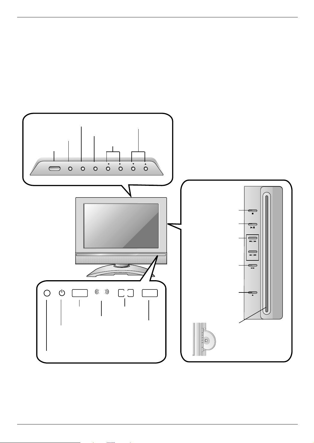
Controls
Controls
Menu Button
Enter Button
TV/Video Button
On/Off Button
Mono Indicator
Power/Standby Indicator
Glows red in Standby mode,
Glows green when the TV is turned on.
Remote Control Sensor
Volume Buttons
Stereo Indicator
Channel Buttons
SAP Indicator
DPM Indicator
Stop Button:
Stops playback
Play/Pause Button:
Start or pause playback
Skip/Scan Button:
Starts playback from
the selected chapter
Repeat Button:
Repeat playback
Open/Close Button:
Open or close the
or track
disc tray
Disc Slot:
Place a disc on the disc slot.
Note : Insert a disc after facing a logo-printed side to
front. See a figure.
6
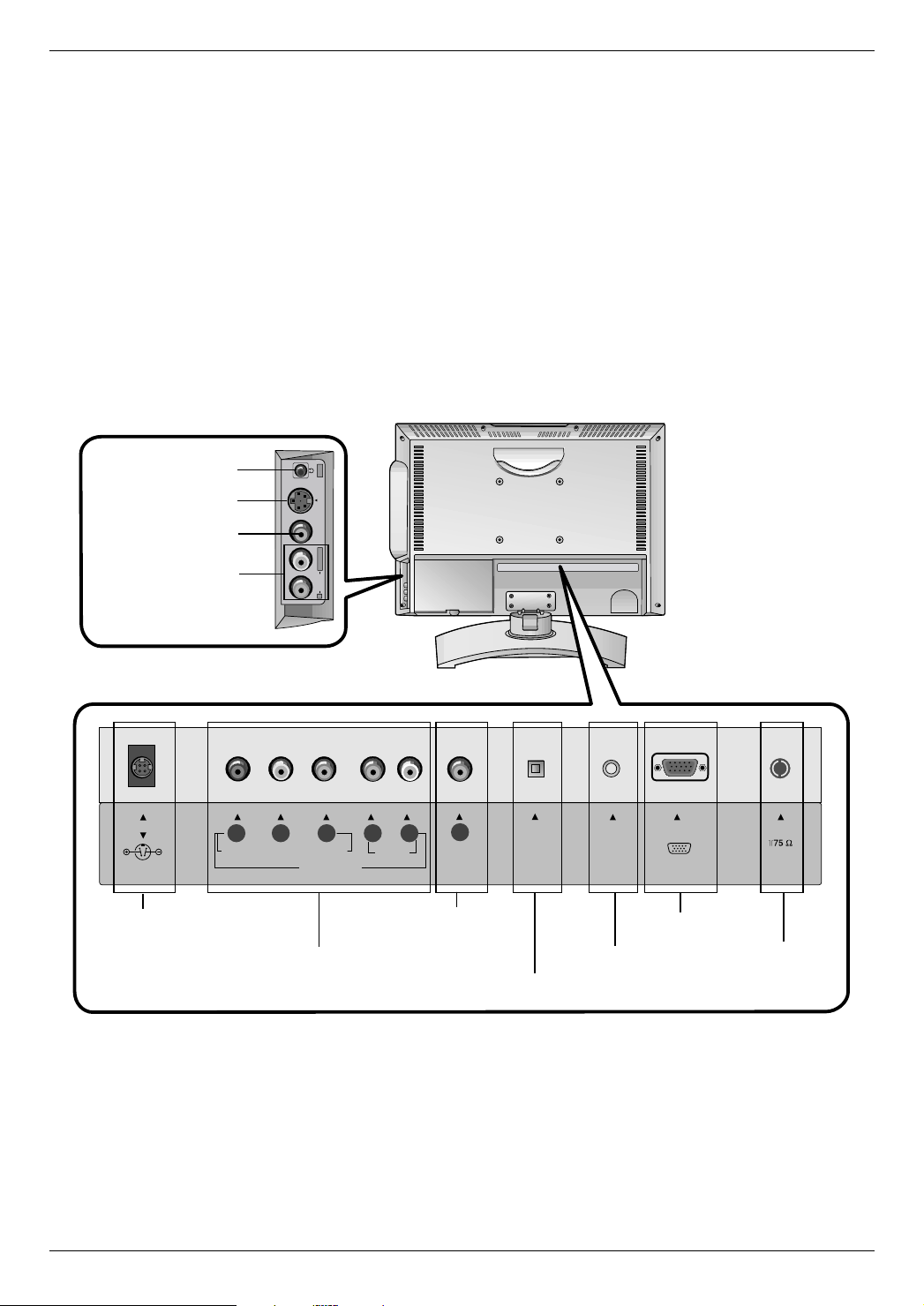
Connection Options
R
S-VIDEO VIDEO
L / MONO
AUDIO
IN
ANT IN
COMPONENT(480i/480p/720p/1080i)
PC
SOUND
DVD/DTV IN
AUDIO
P
R
P
B
Y
DC IN (15V)
LR
PC INPUT
DVD OUT
OPTICAL
DIGITAL
SOUND
OUT
VIDEO
Connection Options
Headphone Jack
S-Video Input
Video Input
Product Overview
Audio Input
DC 15V Input*
*Use with AC adapter.
DVD Video Output
DVD/DTV Input
(Component (480i/480p/720p/1080i), Audio)
PC Sound Input
Digital Sound Optical output
PC Input
Antenna Input
7
Product Overview
123
456
7
video audio
fcr/zoom
8
0
arc
multimedia
9
power
open/close tv/video
mute mts/audio
pip cc/sub-t
pip ch pip ch
pip input
exit
pip swap
menu ch
vol
enter
vol
ch
play/pause
/II
a-b
disc menu
3D sound
program
title menu
flashbk/angle
repeat
stop
still
scan
sizeposition
sleep
skip
scan
skip
scan
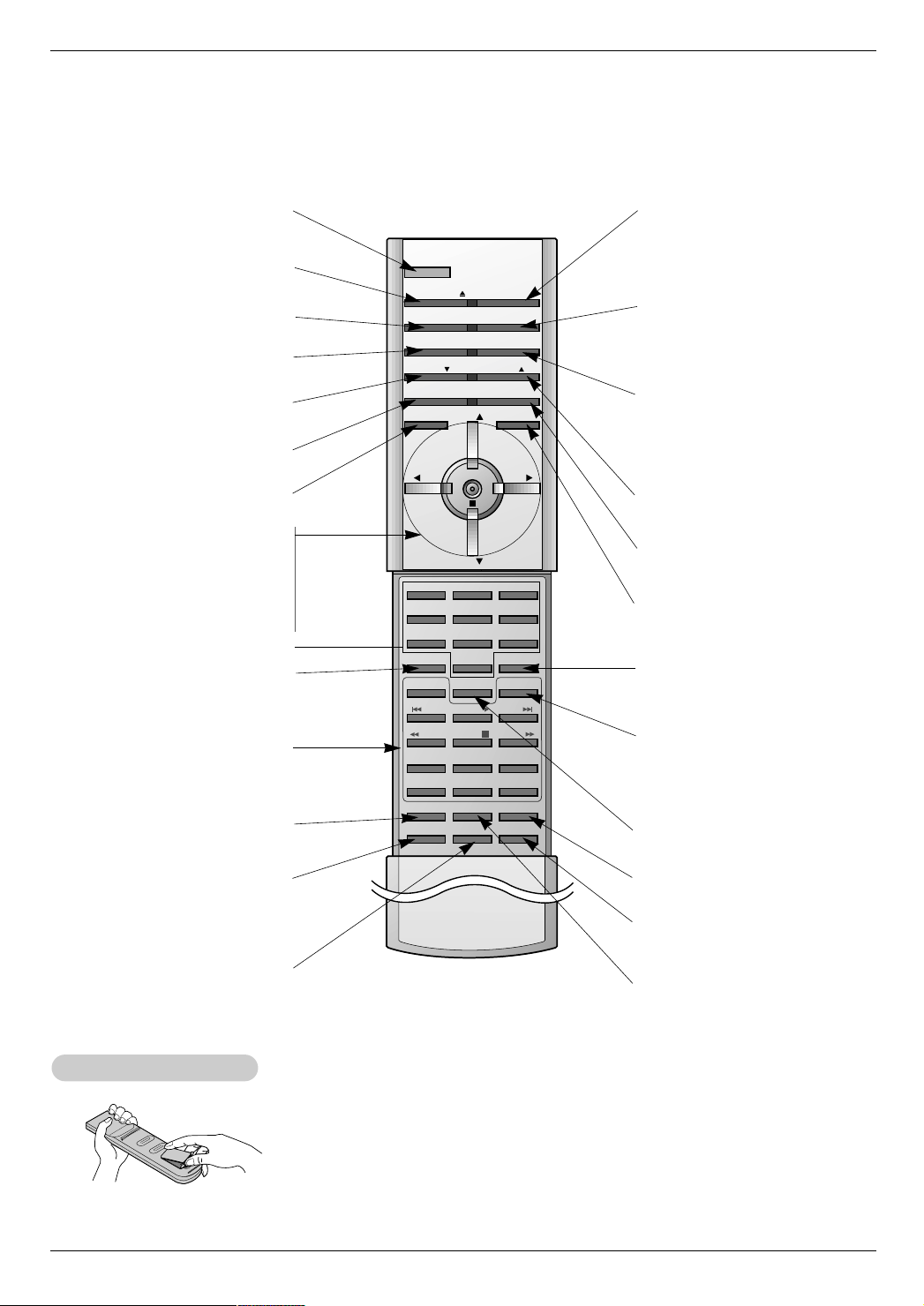
Remote Control Key Functions
Remote Control Key Functions
- When using the remote control, aim it at the remote control sensor on the TV.
POWER
Switches the TV between
ON and STANDBY.
OPEN/CLOSE
Opens or closes the disc slot.
MUTE
Use to turn the sound on or off temporarily.
PIP
Selects PIP or Double window mode.
PIP CH
E
Tunes to next lower PIP channel.
PIP SWAP
Exchanges the sub/main images.
MENU
Displays the main menu on the screen.
ENTER
CH
Selects available channels found
(Channel button)
DD/ EE
with EZ scan.
VOL FF / GG (Volume button)
Decreases/increases the sound level.
Selects a factory preset picture
NUMBER buttons
VIDEO
according to the room.
DVD BUTTON
Controls the DVD player.
For further details, see the
‘DVD Operation’ section.
SLEEP
Sets the Sleep Timer.
Freezes the currently-viewed picture.
Sub picture is frozen in PIP/Twin pic-
(Refer to p.29)
Installing Batteries
Installing Batteries
STILL
ture mode.
SCAN
TV/VIDEO
Selects:
DVD, Component, or RGB-PC
mode.
MTS/AUDIO
Selects MTS sound: Mono, Stereo,
or SAP.
Changes the AUDIO during DVD
playback.
CC/SUB-T
Selects closed caption options: Off,
EZ Mute, or On.
Changes the subtitle language during
DVD playback.
PIP CH
Tunes to next higher PIP channel.
PIP INPUT
Selects the input source for the sub
picture.
EXIT
Clears all on-screen displays and
returns to TV viewing from any menu.
AUDIO
Selects the sound appropriate for the
program's character.
FCR/ZOOM
Press this button to return to the last
channel you were watching.
Changes the picture size during DVD
playback.
ARC
Changes the aspect ratio.
SIZE
Changes the sub picture size.
MULTIMEDIA
Selects: TV, DVD, Component, or
RGB-PC mode.
POSITION
Changes the sub picture position.
• Open the battery compartment cover on the back side and
insert the batteries with correct polarity.
• Install two 1.5V batteries of AAA type. Don’t mix used batteries
with new batteries.
TV, Video, S-Video,
D
8
Installation
1.5V
1.5V
123
456
7
video audio
fcr/zoom
8
0
arc
multimedia
9
power
open/close tv/video
mute mts/audio
pip cc/sub-t
pip ch pip ch
pip input
exit
pip swap
menu ch
vol
enter
vol
ch
play/pause
/II
a-b
disc menu
3D sound
program
title menu
flashbk/angle
repeat
stop
still scan
sizeposition
sleep
skip
scan
skip
scan
Installation
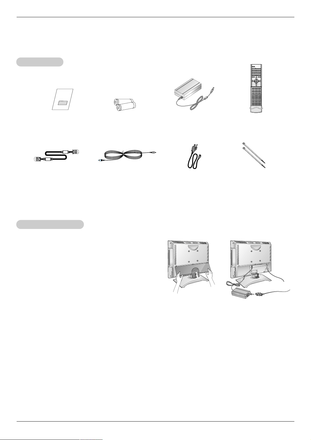
Accessories
Accessories
Installation
Operating Guide
PC Signal Cable
Power Connections
Power Connections
AAA Batteries
PC Sound Cable
* Caution: Please be sure to connect the TV to the AC power adapter
before connecting the TV's power plug to a wall power outlet.
a. Remove the connection panel cover as shown below.
b. Connect the antenna cable to the antenna input port on the TV.
c. Connect the AC adapter plug to the power input jack on the TV.
d. Connect the power cord to the AC adapter first, then plug the
power cord into the wall power outlet.
e. Reinstall the connection panel cover.
AC Adapter
Power Cord
a
Remote Control
Tie Bands
- Arrange the wires
with the tie bands.
b
d
c
NOTES
a. If the TV feels cold to the touch, there may be a small “flicker” when it is turned on.
This is normal, there is nothing wrong with TV.
b. Some minute dot defects may be visible on the screen, appearing as tiny red, green, or blue spots. However, they have no
adverse effect on the monitor's performance.
c. Avoid touching the LCD screen or holding your finger(s) against it for long periods of time.
Doing so may produce some temporary distortion effects on the screen.
9
Installation
3
12
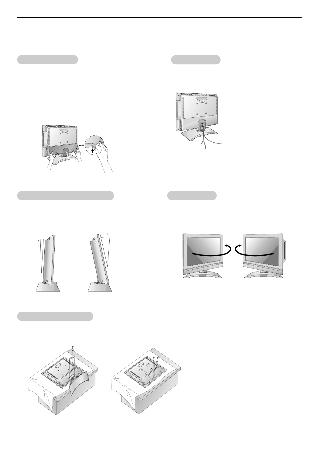
Installation Instructions
Installation Instructions
Rear
A/V Cover
Rear
A/V Cover
ire Holders
WWire Holders
* The connection panel is hidden behind the A/V cover.
a. Remove the cover.
b. Install wires as necessary.
c. Reinstall the cover. Position the A/V cover with the TV
back panel, tilt it back as shown.
d. Align the holes on the TV back panel with the two tabs
on the rear A/V cover and insert.
e. Close cover.
Adjusting the
Adjusting the
- You can adjust the vertical viewing angle of the TV
between 3° and 12°.
TV V
TV V
iewing
iewing
Angle
Angle
- Thread, then pull the wires through the hole on the TV
stand.
Swivel Stand
Swivel Stand
- The TV can be conveniently swiveled on its stand 30° to
the left or right to provide the optimum viewing angle.
Installation on the W
Installation on the W
- An optional wall mount is available for this TV, see your dealer.
For installation, follow the instructions provide with the optional wall mount.
10
all
all
External Equipment Connections
ANT INPC INPUT
ANT INPC INPUT
External Equipment Connections
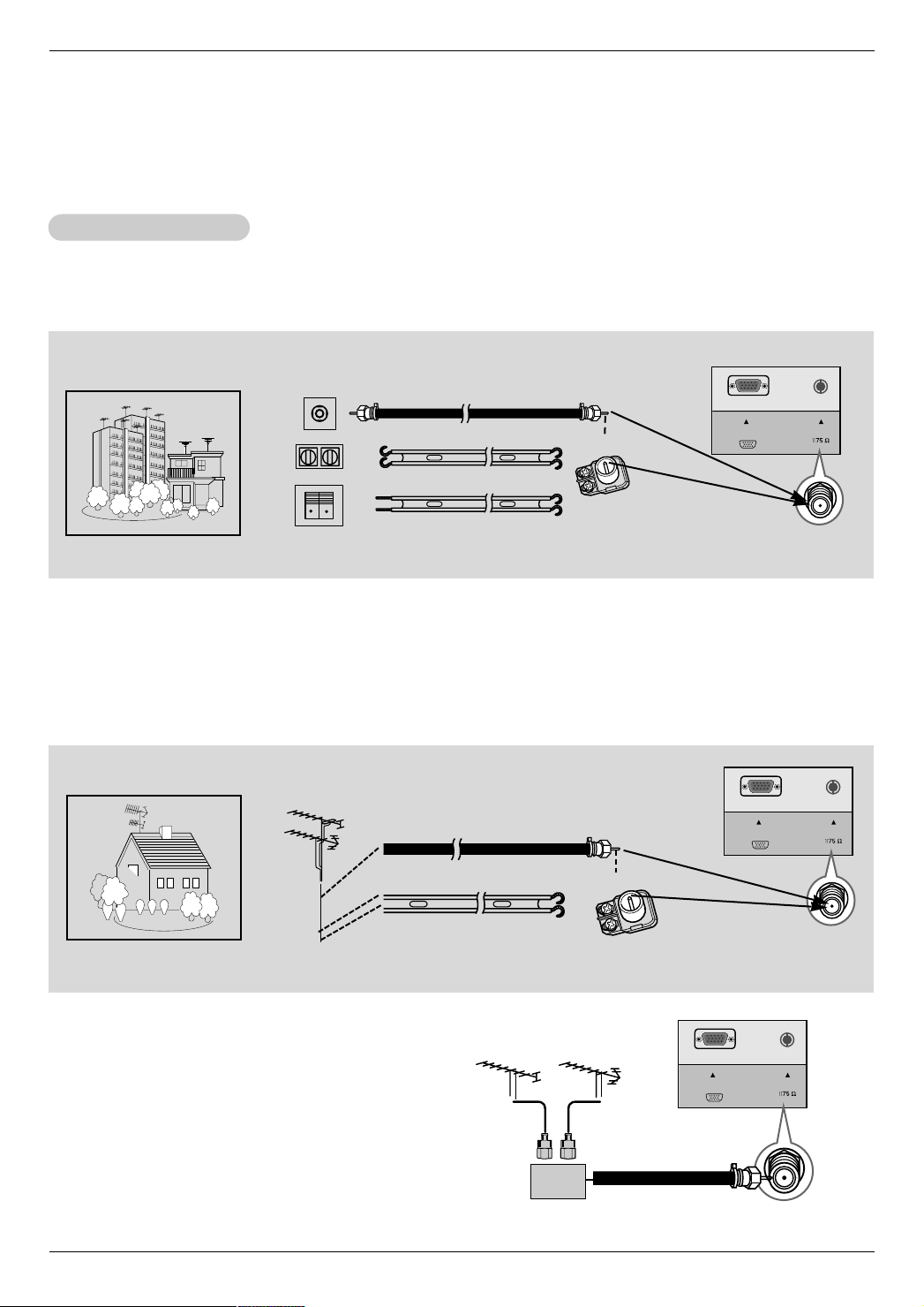
Antenna Connection
Antenna Connection
- For optimum picture quality, adjust antenna direction.
Connecting to an Inside Antenna Setup
- Typical wall antenna jack used in apartment buildings, connect the antenna cable as shown below.
(Use the correct type of antenna cable for the type of wall antenna jack.)
Turn clockwise to tighten.
Installation
Apartment Buildings
75Ω Round Cable
300Ω Flat Wire
Wall Connection Jack
Bronze Wire
Antenna
Converter
Antenna Jack
- If you have a 75Ω round cable, insert the bronze wire and then tighten the connection nut. If you have a 300Ω flat wire, connect
the twisted wire to the antenna converter and then connect the converter to the antenna jack on the TV.
- If using 75Ω round cable, do not bend the bronze wire. It may cause poor picture quality.
Connecting to an Outside Antenna Setup
- This type of antenna is commonly used in single family dwellings.
Single Family Home
UHF
Antenna
VHF Antenna
75Ω Round Cable
300Ω Flat Wire
Turn clockwise to tighten.
Bronze Wire
Antenna
Converter
Antenna Jack
- In poor signal areas, to get better picture quality, install a
signal amplifier to the antenna as shown to the right.
- If signal needs to be split for two TVs, use an antenna
signal splitter for connection.
VHF
Signal
Amplifier
UHF
ANT INPC INPUT
11
Installation
ANT INPC
SOUND
PC INPUT
OPTICAL
DIGITAL
SOUND
OUT
OUT
IN
CH3 CH4
S-VIDEO
ANT IN
ANT OUT
(R) (L)
AUDIO VIDEO
R
S-VIDEO VIDEO
L / MONO
AUDIO
IN
ANT INPC
SOUND
PC INPUT
OPTICAL
DIGITAL
SOUND
OUT
TV
VCR
(R) AUDIO (L) VIDEO
RF Cable
R
S-VIDEO VIDEO
L / MONO
AUDIO
IN
R
S-VIDEO VIDEO
L / MONO
AUDIO
IN
RL
AUDIO VIDEO
External Equipment Connections Continued
External Equipment Connections Continued
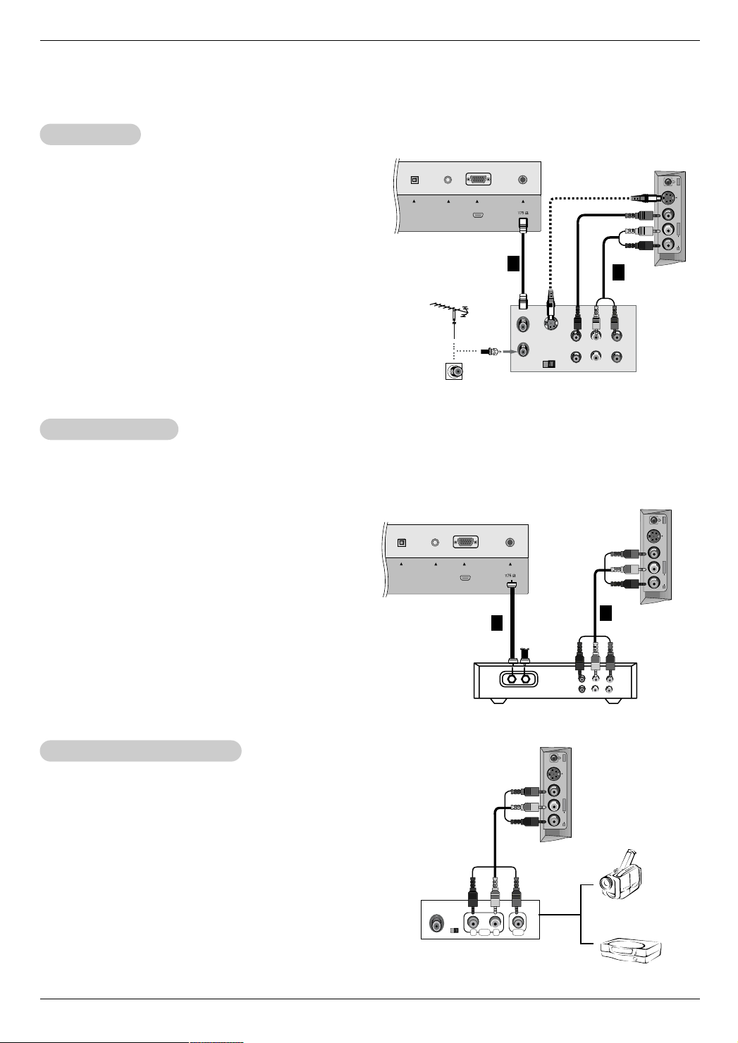
VCR Setup
VCR Setup
Connection 1
Set VCR switch to 3 or 4 and then tune TV to the same
channel number.
Connection
1. Connect the audio/video output jacks on VCR to the corresponding input jacks on the TV. When connecting the TV
2
TV Back Panel
1
to a VCR, match the jack colors (Video = yellow, Audio
Left = white, and Audio Right = red).
2. Insert a video tape into the VCR and press PLAY on the
VCR. (Refer to the VCR owner’s manual.)
Typical
Antennas
3. Use the tv/video button on the remote control to select
Video. (If connected to S-VIDEO on side panel, select the
S-Video external input source.)
Cable
TV Setup
Cable
TV Setup
Direct
Connection
VCR
- After subscribing to a local cable TV service and installing a converter, you can watch cable TV programming.
- For further cable TV information, contact a local cable service provider.
Connection 1
1. Select 3 or 4 with channel switch on cable box.
2. Tune the TV channel to the same selected output channel
of cable box.
3. Select channels at the cable box or with the cable box
remote control.
Connection 2
1. Connect the audio/video output jacks on Cable Box to the
corresponding input jacks on the TV. When connecting
the TV to Cable Box, match the jack colors
(Video = yellow, Audio Left = white, and Audio Right =
red).
2. Use the tv/video button on the remote control to select
Video.
3. Select channels with the cable box remote control.
TV Back Panel
1
Cable Box
2
2
TV Side Panel
TV Side Panel
External
External
A/V Source Setup
A/V Source Setup
Connections
Connect the audio/video output jacks on the external A/V
equipment to the corresponding input jacks on the TV.
When connecting the TV to external A/V equipment,
match the jack colors (Video = yellow, Audio Left = white,
and Audio Right = red).
Viewing Setup
1. Turn on the external A/V equipment.
2. Use the tv/video button on the remote control to
select Video.
3. Operate the corresponding external equipment. Refer
to external equipment operating guide.
12
TV Side Panel
Camcorder
External Equipment
Video Game set
DVD Setup
ANT IN
+75 Ω
COMPONENT(480i/480p/720p/1080i)
PC
SOUND
DVD/DTV IN
AUDIO
PRP
B
Y LR
PC INPUT
DVD OUT
OPTICAL
DIGITAL
SOUND
OUT
VIDEO
AUDIOYPB PR (L)
(R)
ANT IN
+75 Ω
COMPONENT(480i/480p/720p/1080i)
PC
SOUND
DVD/DTV IN
AUDIO
PRP
B
Y LR
PC INPUT
DVD OUT
OPTICAL
DIGITAL
SOUND
OUT
VIDEO
AUDIOYPB PR (L)
(R)
R
S-VIDEO VIDEO
L / MONO
AUDIO
IN
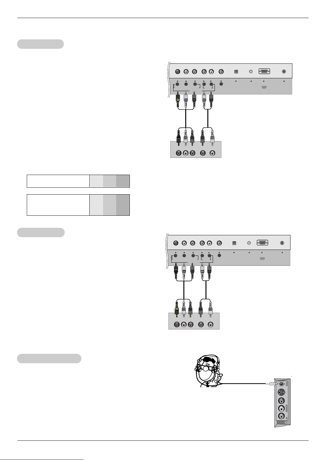
DVD Setup
- This TV can play a DVD without other DVD player.
However, if you do watch a DVD from other DVD
player, refer to the figure as shown right.
Connections
Connect the DVD video outputs to the COMPONENT
, PR) jacks and connect the DVD audio outputs
(Y, PB
to the AUDIO jacks.
Viewing Setup
1. Turn on the DVD player, insert a DVD.
2. Use the tv/video or multimedia button on the remote
control to select Component.
3. Refer to the DVD player's manual for operating
instructions.
• Component Input ports
To get better picture quality, connect a DVD player to
the component input ports as shown below.
Component ports
of the TV
Y PB
R
P
Installation
TV Back Panel
DVD
Video output ports
of DVD player
DTV Setup
DTV Setup
Y
Y
Y
Y
Pb
B-Y
Cb
PB
Pr
R-Y
Cr
P
R
- To watch digitally broadcast programs, purchase
and connect a digital set-top box.
Connections
Connect the digital set-top box video outputs to the
COMPONENT (Y, PB, PR) jacks and connect the
digital set-top box audio outputs to the AUDIO
jacks.
Viewing Setup
1. Turn on the digital set-top box. (Refer to the
owner’s manual for the digital set-top box.)
2. Use the tv/video or multimedia button on the
remote control to select Component.
Using Headphones
Using Headphones
- Plug headphones in to H/P jack as shown.
- Adjust sound level to a headphone using the volume (F, G)
buttons. While you are listening to sound through a headphone(s), TV speakers will not be heard.
TV Back Panel
DTV Receiver (Set-top Box)
13
Installation
ANT IN
+75 Ω
PC
SOUND
PC INPUT
OPTICAL
DIGITAL
SOUND
OUT
ANT IN
+75 Ω
PC
SOUND
PC INPUT
DVD OUT
OPTICAL
DIGITAL
SOUND
OUT
VIDEO
VIDEO
DIGITAL AUDIO
OPTICAL
DVD Output Setup
DVD Output Setup
The TV has a special signal output capability which allows
you to hook up a second TV or monitor.
Connect the second TV or monitor to the TV’ DVD OUTPUT
and OPTICAL DIGITALSOUND OUT jack. See the
Operating Manual of the second TV or monitor for further
details regarding that device’s input settings.
TV Back Panel
Notes: • If your DVD has no optical digital audio input jack,
it’s impossible to use DVD sound output.
• Do not look into the optical output port. Looking at
the laser beam may damage your vision.
• If your external audio equipment has a digital audio
input optical port, you can connect it to your TV.
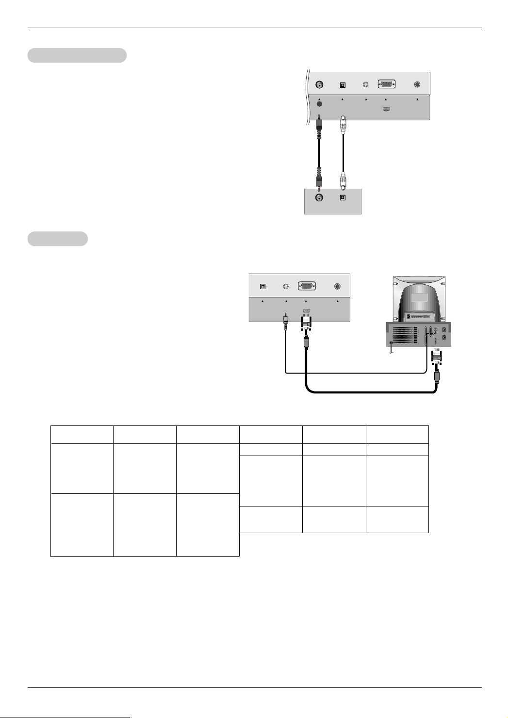
PC Setup
PC Setup
- After setup, be sure to select RGB-PC source on TV.
Connections
1. Set the monitor output resolution on the PC before
connecting to the TV.
2. Connect the TV to the PC with the PC cable.
3. Connect the PC audio output to the TV's PC SOUND
input.
Viewing Setup
1. Turn on the PC.
2. Use the tv/video or multimedia button on the remote
control to select RGB-PC.
Monitor Display Specifications
Resolution
640x480
800x600
Horizontal
Frequency(KHz)
31.4
35
37.5
43.2
35.1
37.8
48
46.8
53.6
Vertical
Frequency(Hz)
60
67
75
85
56
60
72
75
85
TV Back Panel
Resolution
832x624
1024x768
1280x768
Second TV or Monitor
Horizontal
Frequency(KHz)
49.7
48.3
56.4
60
68.6
39.5
47.6
Vertical
Frequency(Hz)
75
60
70
75
85
50
60
NOTES
a. For optimum picture quality, use standard XGA (1024x768) computer output at a 60Hz refresh rate. Using other formats
(VGA, SVGA, etc.) or refresh rates may result in reduced picture quality. (To change the computer video output format,
please refer to the operating manual for the computer you are using).
b. If the message “
Specifications' chart above.
c. The synchronization input form for Horizontal and Vertical frequencies is separate.
Out of range” appears on the screen, adjust the PC output to a format listed in the ‘Monitor Display
DPM (Display Power Management) mode
If the PC goes to power saving mode, the monitor automatically switches to DPM mode.
If you don’t use the PC cable provided, DPM mode may not work.
14
 Loading...