

Page 1

Installation, Setup & Operating Guide I Warranty
Model Number | L15V24S | LCD-TV / Monitor
© Copyright 2002, Zenith Electronics Corporation.
Page 2
WARNING :
WARNING
RISK OF ELECTRIC SHOCK
DO NOT OPEN
TO REDUCE THE RISK OF ELECTRIC SHOCK DO NOT REMOVE COVER (OR BACK).
NO USER SERVICEABLE PAR TS INSIDE. REFER SERVICING TO QUALIFIED SER VICE PERSONNEL.
The lightning flash with arrowhead symbol, within an equilateral triangle, is intended to alert the user to
the presence of uninsulated “dangerous voltage” within the product’s enclosure that may be of sufficient
magnitude to constitute a risk of electric shock to persons.
The exclamation point within an equilateral triangle is intended to alert the user to the presence of important operating and maintenance (servicing) instructions in the literature accompanying the appliance.
WARNING :
TO PREVENT FIRE OR SHOCK HAZARDS, DO NOT EXPOSE THIS PRODUCT TO RAIN OR MOISTURE.
NOTE TO CABLE/TV INSTALLER:
This reminder is provided to call the cable TV system installer’s attention to Article 820-40 of the National
Electric Code (U.S.A.). The code provides guidelines for proper grounding and, in particular, specifies
that the cable ground shall be connected to the grounding system of the building, as close to the point of
the cable entry as practical.
REGULATOR YINFORMATION:
This equipment has been tested and found to comply with the limits for a Class B digital device, pursuant
to Part 15 of the FCC Rules. These limits are designed to provide reasonable protection against harmful interference when the equipment is operated in a residential installation. This equipment generates,
uses and can radiate radio frequency energy and, if not installed and used in accordance with the instruction manual, may cause harmful interference to radio communications. However, there is no guarantee
that interference will not occur in a particular installation. If this equipment does cause harmful interference to radio or television reception, which can be determined by turning the equipment off and on, the
user is encouraged to try to correct the interference by one or more of the following measures:
Any changes or modifications not expressly approved by the party responsible for compliance could void
the user’s authority to operate the equipment
CAUTION:
Do not attempt to modify this product in any way without written authorization from Zenith Electronics
Corporation. Unauthorized modification could void the user’s authority to operate this product. The
responsible party for this product’s compliance is :
Zenith Electronics Corporation, 2000 Millbrook Dr., Lincolnshire, IL60069, USA
1-847-941-8000
2
• Reorient or relocate the receiving antenna.
• Increase the separation between the equipment and receiver.
• Connect the equipment into an outlet on a circuit different from that to
which the receiver is connected.
• Consult the dealer or an experienced radio/TV technician for help.
RECORD YOUR MODEL NUMBER
(For future reference)
The model and serial number of your TV are located on the
back of the TV cabinet. For convenience, we suggest that
you record those numbers here:
MODEL NO._______________________________
SERIAL NO._______________________________
206-3825
Page 3
IMPORTANT SAFETY INSTRUCTIONS
PORTABLE CART WARNING
Important safeguards for you and your new product
Your product has been manufactured and tested with your safety in mind. However, improper use can result
in potential electrical shock or fire hazards. To avoid defeating the safeguards that have been built into your
new product, please read and observe the following safety points when installing and using your new product, and save them for future reference.
Observing the simple precautions discussed in this booklet can help you get many years of enjoyment and
safe operation that are built into your new product.
This product complies with all applicable U.S. Federal safety requirements, and those of the Canadian
Standards Association.
1. Read Instructions
All the safety and operating instructions should be
read before the product is operated.
2. Follow Instructions
All operating and use instructions should be followed.
3. Retain Instructions
The safety and operating instructions should be
retained for future reference.
4. Heed Warnings
All warnings on the product and in the operating
instructions should be adhered to.
5. Cleaning
Unplug this product from the wall outlet before cleaning. Do not use liquid cleaners or aerosol cleaners.
Use a damp cloth for cleaning.
6. Water and Moisture
Do not use this product near water - for example, near
a bath tub, wash bowl, kitchen sink, or laundry tub, in
a wet basement, or near a swimming pool.
7. Accessories, Carts, and Stands
Do not place this product on an unstable cart, stand,
tripod, bracket, or table. The product may fall, causing
serious injury to a child or adult, and serious damage
to the product. Use only with a cart, stand, tripod,
bracket, or table recommended by the manufacturer,
or sold with the product. Any mounting of the product
should follow the manufacturer’s instructions, and
should use a mounting accessory recommended by
the manufacturer.
8. Transporting Product
A product and cart combination should be moved
with care. Quick stops, excessive force, and uneven
surfaces may cause the product and cart combination to overturn.
9. Attachments
Do not use attachments not recommended by the
product manufacturer as they may cause hazards.
10. Ventilation
Slots and openings in the cabinet are provided for
ventilation and to ensure reliable operation of the
product and to protect it from overheating, and these
openings must not be blocked or covered. The openings should never be blocked by placing the product
on a bed, sofa, rug, or other similar surface. This
product should not be placed in a built-in installation
such as a bookcase or rack unless proper ventilation
is provided or the manufacturer’s instructions have
been adhered to.
11. Power Sources
This product should be operated only from the type
of power source indicated on the marking label. If
you are not sure of the type of power supply to your
home, consult your product dealer or local power
company. For products intended to operate from battery power, or other sources, refer to the operating
instructions.
12. Power-Cord Polarization
This product is equipped with a three-wire grounding
type alternating-current line plug (a plug having one
blade wider than the other). This plug will fit into the
power outlet only one way. This is a safety feature. If
you are unable to insert the plug fully into the outlet,
contact your electrician to replace your obsolete outlet. Do not defeat the safety purpose of the polarized
plug.
13. Power-Cord Protection
Power-supply cords should be routed so that they
are not likely to be walked on or pinched by items
placed upon or against them, paying particular attention to cords at plugs, convenience receptacles, and
the point where they exit from the product.
INTRODUCTION
206-3825
(Continued on next page)
3
Page 4
IMPORTANT SAFETY INSTRUCTIONS
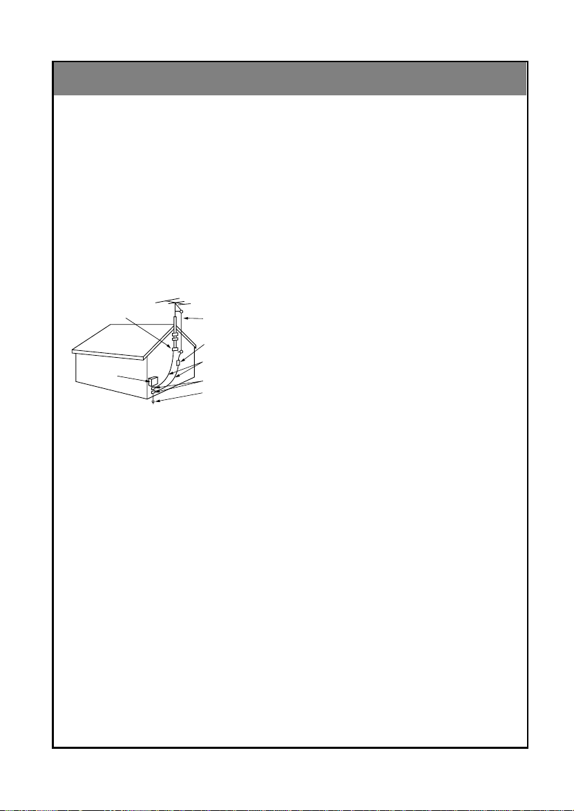
Antenna Lead in Wire
Antenna Discharge Unit
(NEC Section 810-20)
Grounding Conductor
(NEC Section 810-21)
Ground Clamps
Power Service Grounding
Electrode System (NEC
Art 250, Part H)
Ground Clamp
Electric Service
Equipment
(Continued from previous page)
14. Outdoor Antenna Grounding
If an outside antenna or cable system is connected
to the product, be sure the antenna or cable system
is grounded so as to provide some protection against
voltage surges and built-up static charges. Article
810 of the National Electrical Code (U.S.A.), ANSI/
NFPA 70 provides information with regard to proper
grounding of the mast and supporting structure,
grounding of the lead-in wire to an antenna discharge unit, size of grounding conductors, location of
antenna-discharge unit, connection to grounding
electrodes, and requirements for the grounding electrode.
Example of Grounding According to National
Electrical Code Instructions
NEC - National Electrical Code
15. Lightning
For added protection for this product (receiver) during a lightning storm, or when it is left unattended
and unused for long periods of time, unplug it from
the wall outlet and disconnect the antenna or cable
system. This will prevent damage to the product due
to lightning and power-line surges.
16. Power Lines
An outside antenna system should not be located in
the vicinity of overhead power lines or other electric
light or power circuits, or where it can fall into such
power lines or circuits. When installing an outside
antenna system, extreme care should be taken to
keep from touching such power lines or circuits as
contact with them might be fatal.
17. Overloading
Do not overload wall outlets and extension cords as
this can result in a risk of fire or electric shock.
18. Object and Liquid Entry
Never push objects of any kind into this product
through openings as they may touch dangerous voltage points or short-out parts that could result in a fire
or electric shock. Never spill liquid of any kind on the
product.
4
19. Servicing
Do not attempt to service this product yourself as
opening or removing covers may expose you to dangerous voltage or other hazards. Refer all servicing to
qualified service personnel.
20. Damage Requiring Service
Unplug this product from the wall outlet and refer servicing to qualified service personnel under the following conditions:
a. If the power-supply cord or plug is damaged.
b. If liquid has been spilled, or objects have fallen
into the product.
c. If the product has been exposed to rain or water.
d. If the product does not operate normally by following
the operating instructions. Adjust only those controls
that are covered by the operating instructions as an
improper adjustment of other controls may result in
damage and will often require extensive work by a
qualified technician to restore the product to its normal
operation.
e. If the product has been dropped or the cabinet has
been damaged.
f. If the product exhibits a distinct change in performance.
21. Replacement Parts
When replacement parts are required, be sure the
service technician has used replacement parts specified by the manufacturer or have the same characteristics as the original part. Unauthorized substitutions may result in fire, electric shock, or other hazards.
22. Safety Check
Upon completion of any service or repairs to this
product, ask the service technician to perform safety
checks to determine that the product is in proper operating condition.
23. Wall or Ceiling Mounting
The product should be mounted to a wall or ceiling
only as recommended by the manufacturer. The
product may slide or fall, causing serious injury to a
child or adult, and serious damage to the product.
24. Heat
The product should be situated away from heat
sources such as radiators, heat registers, stoves, or
other products (including amplifiers) that produce
heat.
206-3825
Page 5
Safety Warnings 2
1
Important Safety Instructions 3
Controls 6
Remote Control:
Installing Batteries/ Operation 10
TV Overview 11
Antenna Connections 12
2
VCR Connections 13
External Equipment Connections 14
PC/Computer Connections 15
PC Mode Functions Check 17
INTRODUCTION
INSTALLATION
CONTENTS
INDEX
Before operating the
TV, please read this
manual carefully.
Turning the TV on 18
3
TV Mode Available Menus 19
Menu Language Selection 20
Auto Programming:
Finding/Erasing channels 21
Favorite Channel Memory 23
Setting the Clock 24
4
Setting the Off Timer 25
Setting the On Timer 26
Sleep Timer Setup 27
Video/Picture Setup 28
5
Audio/Sound Setup 31
Closed Captions 37
6
Parental Control 40
Auto Off 42
Key Lock 43
External Control Device Setup 44
Maintenance 49
7
Product Specifications 50
Troubleshooting Check List 51
Your Zenith Limited Warranty Back cover
BASIC
FEATURES
CLOCK/
TIMERS
VIDEO /
AUDIO
SPECIAL
FEATURES
MISC.
206-3825
5
5
Page 6
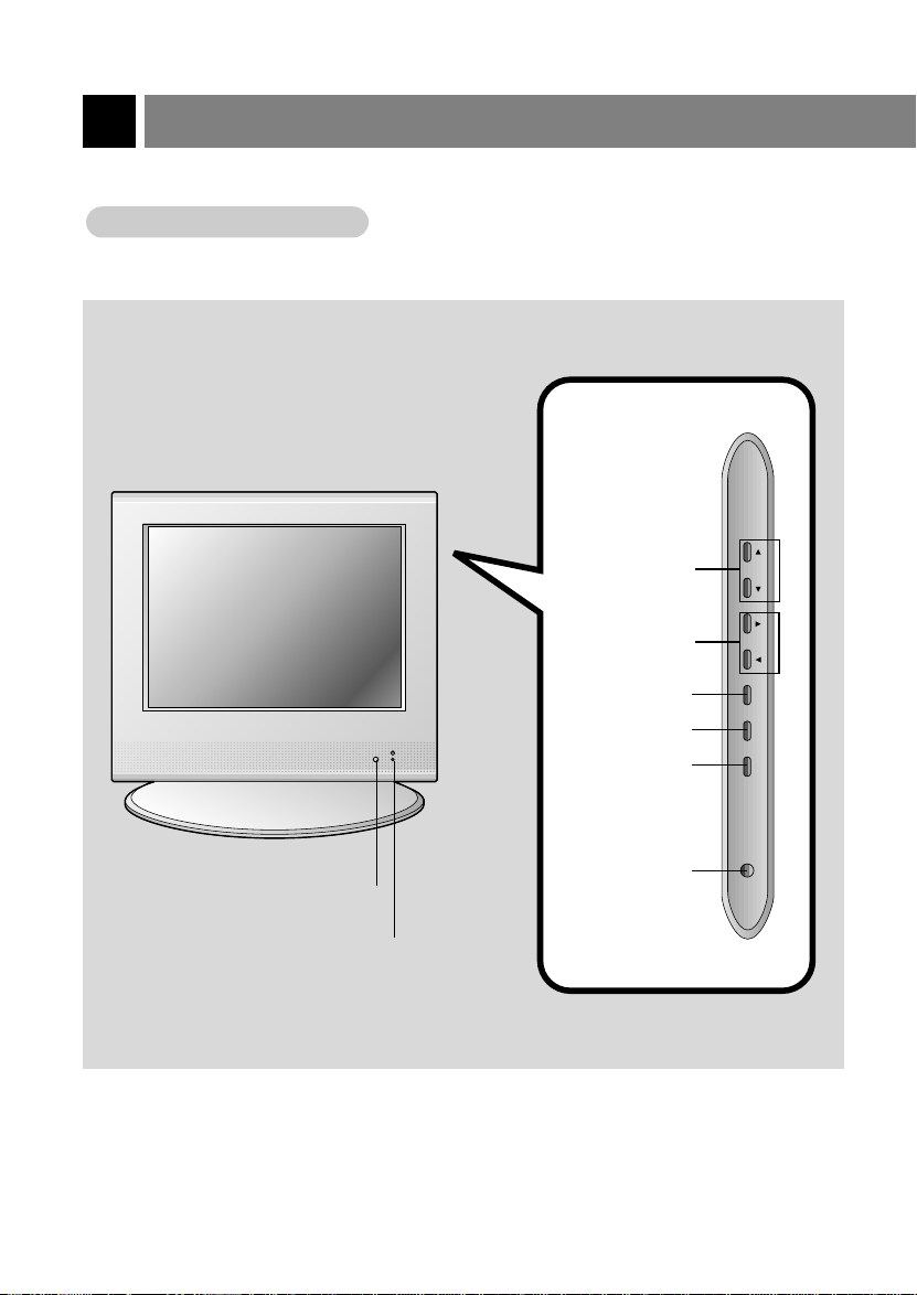
Controls
Front of the TVTV
Front of the
Side Control Panel
Side Control Panel
Channel Buttons
Volume Buttons
Enter Button
Menu Button
TV/Video Button
ch
vo
l
e
n
te
r
m
e
n
u
tv/v
id
eo
on
/off
On/Off Button
Remote Control Sensor
Power/Standby indicator
Illuminates brightly when the
TV is in standby mode. Dims
when the TV is switched on.
206-3825
6
Page 7
+75 Ω
PC INPUT ANT IN
S-VIDEO
H/P
PC
SOUND(120V) INPUT
RS-232CAC INPUT
VIDEO IN
RLVIDEO AUDIO(MONO)
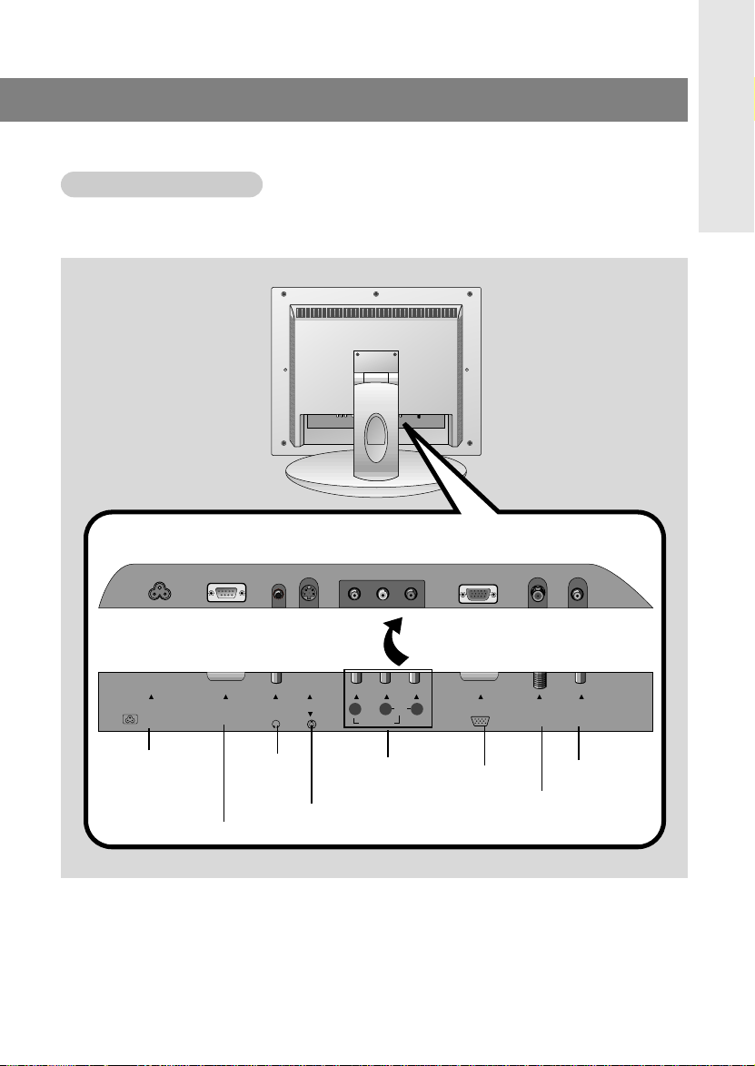
Back of the TVTV
Back of the
Connection Panel
Connection Panel
INTRODUCTION
Power Cord Socket
- This TV operates on
AC power. Never
attempt to operate the
TV on DC power.
206-3825
RS-232C Port
Headphone
Jack
S-Video Input
Audio/Video
Input
PC Input
PC Sound
Antenna Input
7
Page 8
power
apc
menu
mute
sleep
ch
enter
vol vol
ch
cc
tv/video
0
23
564
897
1
mts
fcr
memory/erase
a.prog
flashbk dasp
controls
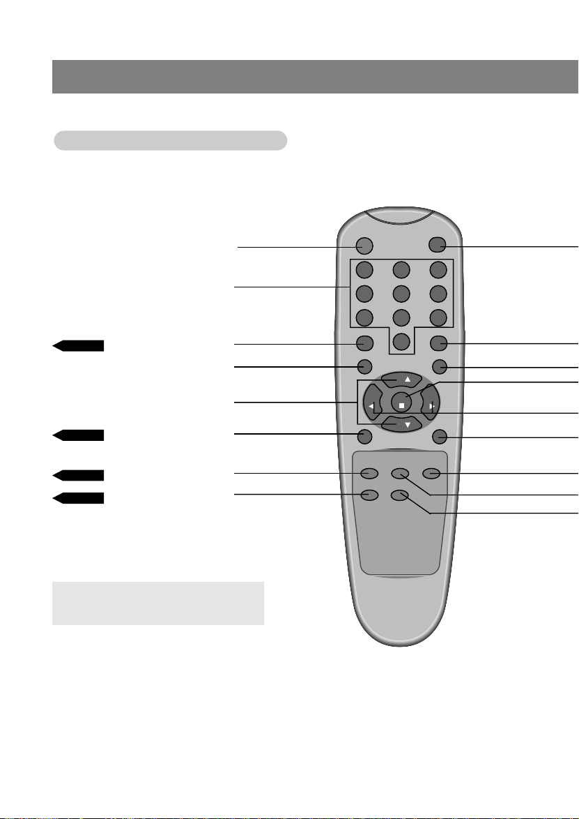
Remote Control Buttons
Remote Control Buttons
POWER
NUMBER
PAGE 28
CHANNEL (DE)
APC
MENU
PAGE 35
MTS
PAGE 23
PAGE 21
● Press the FLASHBK button to view the last
program you were watching.
AUTO PROGRAM
FCR
8
206-3825
Page 9
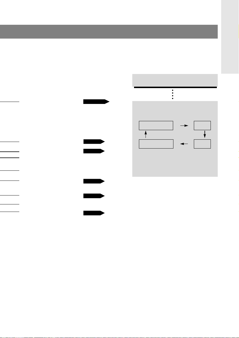
TV/VIDEO Button
TV/VIDEO Button
on Remote Control
on Remote Control
INTRODUCTION
TV/VIDEO
CLOSED CAPTIONS
MUTE
ENTER
VOLUME (
FG
)
SLEEP
DASP
FLASHBK
MEMORY/ERASE
PAGE 13~15
PAGE 39
PAGE 36
PAGE 27
PAGE 31
PAGE 22
- Each press of this button changes the viewing source as indicted below.
TV programs
/Cable TV
- VIDEO, S-VIDEO, PC Select each mode for
watching the corresponding external equipment.
Video
S-VideoPC
206-3825
9
Page 10
Remote Control: Installing Batteries/Operation
power
apc
menu
mute
sleep
ch
enter
vol vol
ch
cc
tv/video
0
23
564
897
1
mts
fcr
memory/erase
a.prog
flashbk dasp
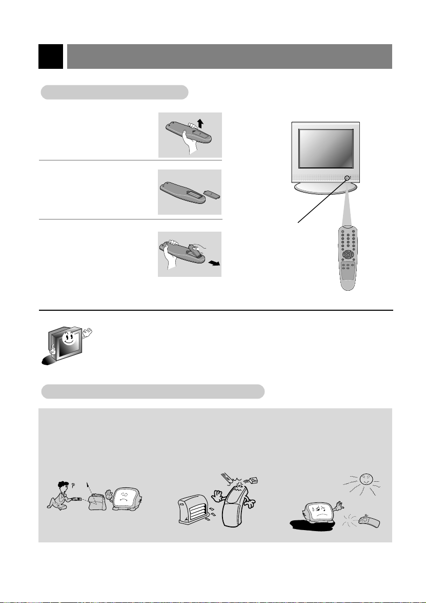
Installing Batteries
Installing Batteries
Pull the battery cover
upward in the direction
1
shown by the arrow
and remove it.
Insert the batteries
with correct polarity,
2
match "+" and "-".
Replace the battery
compartment cover.
3
- Install two AAA, 1.5V alkaline batteries. Don’t mix used batteries with new batteries.
- Remove batteries when you won’t use the remote control for a long time. Liquid leakage
from batteries may damage the remote.
Notes For Using Remote Control
Notes For Using Remote Control
Make sure there are no
objects between the
remote control and its
sensor.
Don’t place the remote control
near a heater or in a damp
place. Astrong impact on
remote control may damage it.
Remote
Control Sensor
Signal from the remote control
may be disturbed by sun light
or other strong light. In this
case, darken the room.
10
206-3825
Page 11
TV Overview
-3°
15°
1.5V
1.5V
power
apc
menu
mute
sleep
ch
enter
vol vol
ch
cc
tv/video
0
23
564
897
1
mts
fcr
memory/erase
a.prog
flashbk dasp
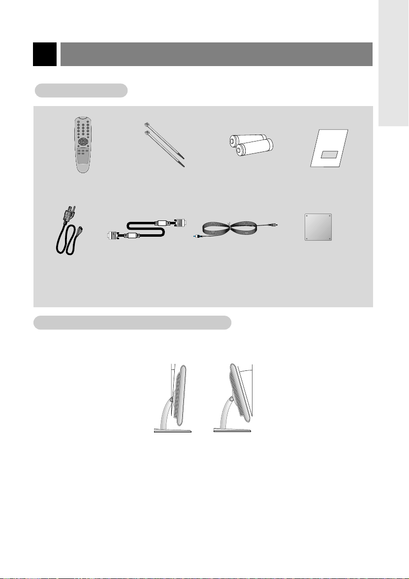
Accessories
Accessories
INTRODUCTION
Remote control
Power cord
Adjusting the
Adjusting the
Tie bands
- Arrange the device wires
with the tie bands.
Batteries
PC signal cable PC sound cable
TV V
TV V
iewing
iewing
Angle
Angle
AAA
Operating guide
VESA standard
mounting interface
- If you intend to mount the TV
to a wall, attach this plate to
the back of the TV.
- You can adjust the angle of the TV between -3° and 15° (Deviation: -3°±3 and 15°±3).
Notes:
● If the TV feels cold to the touch, there may be a small “flicker” when turned on.
This is normal, there is nothing wrong with TV.
● Some minor defects may appear on the screen, like red, green or blue spots.
However, they will have no adverse effect on the monitor's performance.
● Avoid touching the LCD screen or holding your finger(s) against it for long periods of time.
Doing so may produce some temporary distortion effects on the screen.
206-3825
11
Page 12
Antenna Connections
+75 Ω
PC INPUT ANT IN
PC
SOUND
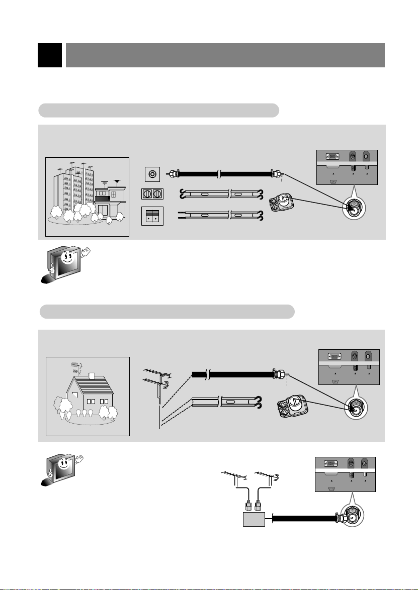
- For optimum picture quality, adjust antenna direction.
Connecting to an Inside
Connecting to an Inside
● Typical wall antenna jack used in apartment buildings. Connect the antenna cable as shown below.
(Use the correct type of antenna cable for the type of wall antenna jack.)
Apartment Buildings
- If you have a 75Ω round cable, insert the bronze wire and then tighten the connection
nut. If you have a 300Ω flat wire, connect the twisted wire to the antenna converter and
then connect the converter to the antenna jack on the TV.
- When using 75Ω round cable, do not bend the bronze wire. It may cause poor picture
quality.
Connecting to an Outdoor
Connecting to an Outdoor
● This type of antenna is commonly used in single family dwellings.
Wall Connection Jack
VHF Antenna
UHF
Antenna
Single Family Dwelling
Antenna Setup
Antenna Setup
Turn clockwise to
75Ω Round Cable
300Ω Flat Wire
Antenna Setup
Antenna Setup
Turn clockwise to
75Ω Round Cable
300Ω Flat Wire
tighten.
Bronze Wire
Antenna
Converter
tighten.
Bronze Wire
Antenna
Converter
Antenna jack
PC INPUT ANT IN
Antenna jack
+75 Ω
SOUND
PC
12
- In poor signal areas, to get better
picture quality, install the antenna as
shown to the right.
- If antenna is split for two TVs, use
signal splitter for connection.
VHF
signal
Amplifier
UHF
PC INPUT ANT IN
+75 Ω
PC
SOUND
206-3825
Page 13
VCR Connection and Viewing Setup
- In Video mode, TV automatically reverts to TV mode if the fcr button or flashbk button are pressed.
- See following pages to connect to other A/V external equipment to input jacks on the TV.
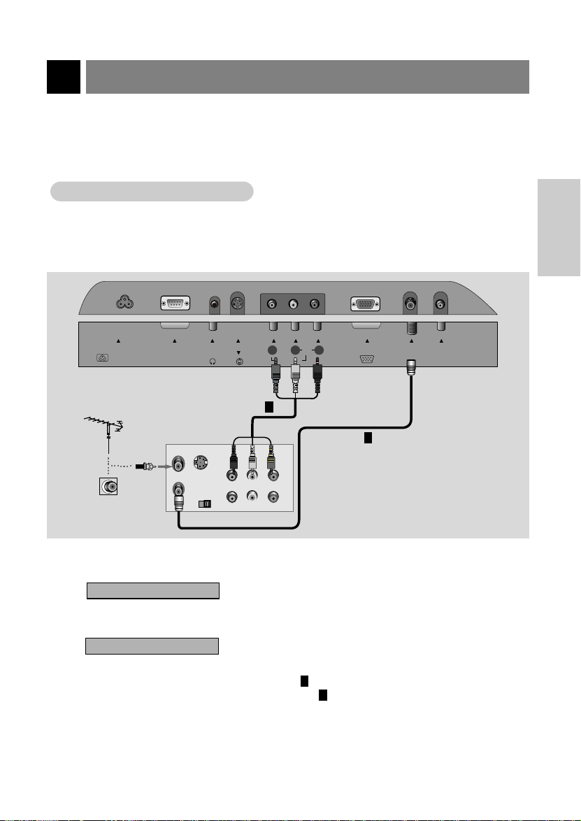
Connecting a VCR
Connecting a VCR
Connections
1
● Connect the audio/video output jacks on VCR to the corresponding input jacks on the TV.
H/P
RS-232CAC INPUT
S-VIDEO
VIDEO IN
RLVIDEO AUDIO(MONO)
PC INPUT ANT IN
RL
+75 Ω
PC
SOUND(120V) INPUT
INSTALLATION
Typical
Antennas
ANT IN
S-VIDEO
Direct
connection
ANT OUT
OUT
IN
CH3 CH4
AUDIO VIDEO
(R) (L)
VCR Connection Panel
Viewing Setup
2
Watching TV programs
Turn the TV on and tune to a channel.
Watching VCR
a. Use tv/video button on the remote control to select Video mode.
2
- Select channel 3 or 4 for ANT IN connection .
- Select VIDEO to use Audio/Video In connections .
b. Insert a video tape into the VCR and press the PLAYbutton.
206-3825
1
2
1
13
Page 14
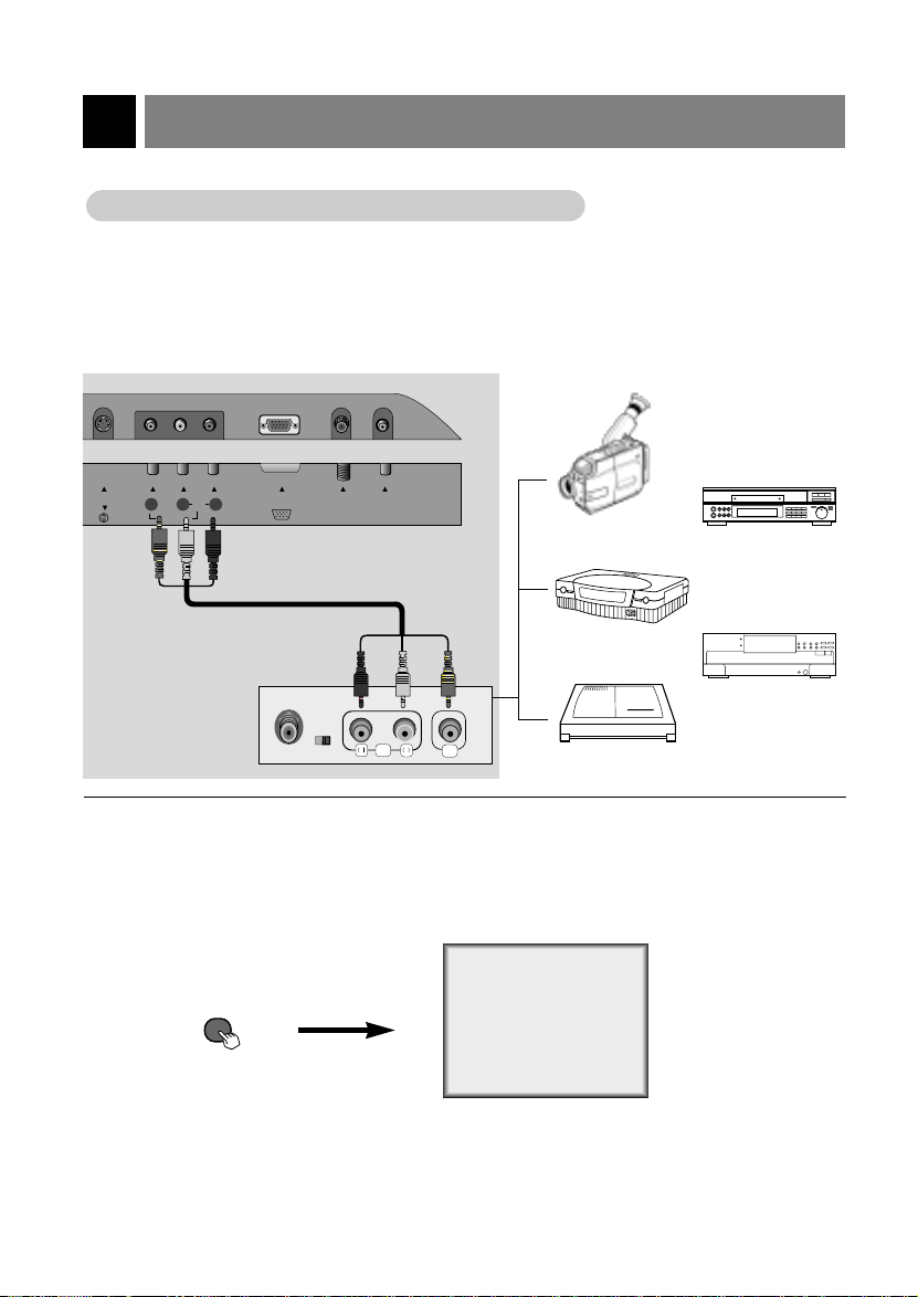
External Equipment Connections
tv/video
atching External
WWatching External
A/V Source
A/V Source
Connections
1
● Connect the audio/video output jacks on the external A/V equipment to the corresponding input jacks
on the TV.
S-VIDEO
External Equipment
Connection Panel
VIDEO IN
RLVIDEO AUDIO(MONO)
PC INPUT ANT IN
+75 Ω
TV Connection Panel
PC
SOUND
AUDIO VIDEO
R
L
Camcorder
Video Game set
CDI
CDGP
VCDP
Viewing Setup
2
● Turn on the external A/V equipment.
● Turn the TV on and use tv/video button to select Video mode.
On Remote Control
14
Video
206-3825
Page 15
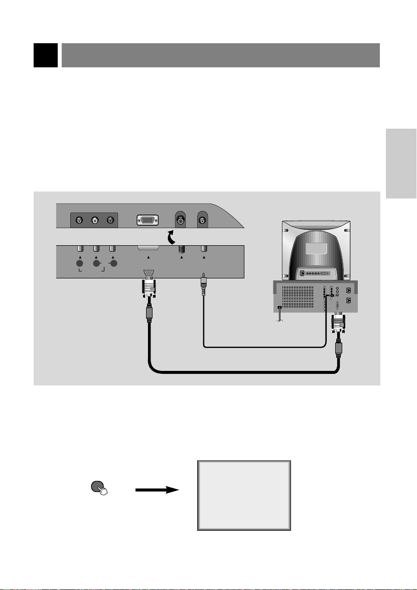
PC/Computer Connections (using the TV as a Monitor)
tv/video
- After setup, be sure to select RGB-PC to see the PC image on TV screen.
Connections
1
● Set the monitor output resolution on the PC before connecting to the TV. See the next page.
● Connect the TV to the PC with the PC cable.
● Connect the PC audio output to the TV's PC SOUND input.
RLVIDEO AUDIO(MONO)
VIDEO IN
TV Connections Panel
PC INPUT ANT IN
+75 Ω
PC
SOUND
PC Connections Panel
INSTALLATION
2
206-3825
Viewing Setup
● Turn on the PC/Computer.
● Turn the TV on and use tv/video button to select PC mode.
PC
On Remote Control
15
Page 16

PC/Computer Connections (using TV as a Monitor)
Displayable Monitor Output Format Specifications
MODE Resolution
640x400
640x480
VGA
SVGA
(MAC)
XGA
640x480
640x480
640x480
800x600
800x600
800x600
800x600
800x600
832x624
1024x768
1024x768
1024x768
Horizontal
Frequency (KHz)
37.9KHz
35.0KHz
37.9KHz
37.5KHz
43.3KHz
35.2KHz
37.9KHz
48.1KHz
46.9KHz
53.7KHz
49.7KHz
48.4KHz
56.5KHz
60.2KHz
Vertical
Frequency (Hz)
85Hz
67Hz
72Hz
75Hz
85Hz
56Hz
60Hz
72Hz
75Hz
85Hz
75Hz
60Hz
70Hz
75Hz
Notes
● For optimum picture quality, use standard XGA (1024x768) computer output at a 60Hz refresh
rate. Using other formats (i.e.: VGA, SVGA, etc) or refresh rates may result in reduced picture
quality. (To change the computer video output format, please refer to the operating manual for the
computer you are using).
● The synchronization input form for Horizontal and Vertical frequencies is separate.
16
206-3825
Page 17

PC Mode Functions Check
- After setup, be sure to select PC source to see the PC image on TV screen.
Use the menu button to display the available menu shown below.
1
Contrast 80
Brightness 60
H-Position 0
V-Position 0
Clock 40
Phase 16
Auto configure
Reset
MoveFGAdjust Menu
DE
● H-Position/V-Position
Adjusts picture left/right and up/down.
The adjustment ranges are -100~+100 / -30~+30.
● Clock
Minimizes any vertical bars or stripes appearing on the screen background.
The adjustment range is 0~80.
● Phase
Remove any horizontal noise and clear up or sharpen the character images.
The range adjustment is 0~31.
● Auto-configure
Automatically adjusts the screen position, clock and clock phase.
(The displayed image will disappear for a few seconds while Auto-configuration is in progress.)
● Reset
Returns to the default settings programmed at the factory; default settings
cannot be changed.
INSTALLATION
206-3825
17
Page 18

Turning the TV On
TV Operation Overview
TV Operation Overview
First, connect antenna cable and power cord correctly. At this moment,
the TV is switched to standby mode.
1
● In standby mode, press the power, ch (
remote control or ch (
TV.
Select the viewing source by pressing tv/video on the remote control.
2
3
● Note: See page 21 if you have not auto programmed the TV to receive channels in
your local broadcast area.
After viewing, press the power button on the remote control. The TV
reverts to standby mode.
), tv/video and on/off on the TV side panel to turn on the
D,E
), tv/video and number buttons on the
D,E
atching
WWatching
Press power on the remote control to turn the TV on.
TV programs
TV programs
1
Use the channel (
) or number buttons to select a channel to view.
D,E
2
Adjust volume level.
3
● Volume (
● Volume (
18
) button increases the sound level.
G
) button decreases the sound level.
F
- If you will be away on vacation, disconnect the power plug from the wall power
outlet.
Volume 45
206-3825
Page 19

TV Mode Available Menus
Press the menu button repeatedly to display the available menus shown below.
1
Auto program
Manual program
Favorite channel
MoveGNext Menu
DE
Language English
Captions Off
Caption/Text CC 1
Key lock Off
Parental Ctl
MoveFGAdjust Menu
DE
APC Clear
Contrast 85
Brightness 50
Color 70
Sharpness 50
Tint 0
MoveFGAdjust Menu
DE
DASP
Balance 0
AVL Off
MoveGNext Menu
DE
Clock
Off timer
On timer
Auto off Off
-- : --
AM
BASIC
FEATURES
Use the channel (
2
206-3825
) buttons to select a menu option.
D,E
MoveGNext Menu
DE
19
Page 20

Menu Language Selection
Language
Language
Use the menu button to select the
menu shown.
1
Language English
Captions Off
Caption/Text CC 1
Key lock Off
Parental Ctl
MoveFGAdjust Menu
DE
Use the volume (
select the language for the menus to
2
appear in.
Language English
Captions Off
Caption/Text CC 1
Key lock Off
Parental Ctl
MoveFGAdjust Menu
DE
● Each press of volume (
selects languages in the order shown
below.
English
Press the menu button to save.
F, G
F, G
Español
3
) buttons to
) buttons
Français
20
206-3825
Page 21

Auto Programming: Finding/Erasing Channels
- For Auto program to work, the programming source must be connected to the TV and the TV must be
receiving programming signals either over-the-air or from a cable-type service provider.
Channel Search (Auto Programming)
Channel Search (Auto Programming)
Press the a.prog button on the
remote control.
1
Auto program
FG
Press the a.prog or volume (
buttons to begin the channel search.
2
● Wait for auto program to complete the
channel search cycle before choosing a
channel. The TV scans for over-the-air
channels and then channels provided by
a cable service.
Channel number being
memorized is displayed.
Auto program TV 63
Stop :
A
34%
F, G
)
BASIC
FEATURES
206-3825
- When the channel search is complete, use the channel (
channels.
- If you press the enter (A) button in auto programming, the function will stop and only channels
programming up to that time will remain.
- Auto programming function can memorize only the channels which are being received at that
time.
) buttons to review the memorized
D,E
21
Page 22

Auto Programming: Finding/Erasing Channels
Memorizing/Erasing Channels
Memorizing/Erasing Channels
- Select Memory (to add the channel) or Erase (to delete the channel from memory).
Use the memory/erase button on the remote control.
1
Manual program
TV 7 Memory
FG
Use the channel (
add to memory or erase and then use the
2
volume (
● Each time you press the volume (
Memory and Erase, as shown.
Press the enter (A) button to save.
3
● The current channel is added to Memory or Erased from the channel list.
22
) buttons to select Memory (add) or Erase (delete).
F, G
Manual program
TV 7 Memory
) buttons to select a channel you want to
D,E
Memory
FG
F, G
Erase
memory/erase or
The current channel number is displayed.
) buttons, you toggle between
206-3825
Page 23

Favorite Channel Memory
- This function is a convenient feature that lets you quickly scan up to five channels of your choice without
having to wait for the TV to scan through all the channels in between.
Use the menu button to select the
menu shown below.
1
Auto program
Manual program
Favorite channel
MoveGNext Menu
DE
Use the channel (
select the favorite channel option.
2
D,E
) buttons to
Press the volume (G) and then use the
channel
3
order as favorite channel, then use the
volume
desired channel number as favorite
channel.
i.e) To change channel 2 to channel 30
● Note: The first five channels found by Auto
Program appear on menu, change them to
your favorite channel numbers.
● Repeat this step to memorize other channels.
Press the enter (A) button to save.
(
) buttons to select an
D,E
(
) buttons to select the
F, G
TV 2
TV 4
TV 6
TV 9
TV 11
MoveFGAdjustA Exit
DE
Press the volume (F, G) buttons.
4
TV 30
BASIC
FEATURES
206-3825
- To select the favorite channel mode, press fcr (Favorite Channel Review) repeatedly. The five
channels programmed to be favorites appear on the screen one-after-the-other.
23
Page 24

Setting the Clock
- If current time setting is erased by a power failure or if TV is unplugged, reset the clock.
Use the menu button to select the
menu shown below.
1
Clock
Clock
Off timer
On timer
Auto off Off
MoveGNext Menu
DE
-- : --
AM
Press the volume (G) and then use
2
the channel (
current hour.
Clock
Off timer
On timer
Auto off Off
FG
) buttons to set the
D,E
--
: -- AM
MoveDEAdjust Menu
Press the volume (G) and use the
channel (
3
minute.
● If you hold down the channel (
the minute display is changed in the
sequence of 00 ➔ 01 ➔ 02 ...58 ➔ 59,
and changed in the reverse sequence for
channel (E) button.
) buttons to set current
D,E
--
Clock
Off timer
On timer
Auto off Off
MoveDEAdjust Menu
FG
-- : --
Press the menu button to save.
4
● The clock starts when you press the
menu button.
AM
) button,
D
24
206-3825
Page 25

Off Timer Setup
- Off Timer operates only if the Clock has been set to the current time.
- Off Timer overrides On Timer if they are set to the same time.
Use the menu button to select the
menu below.
1
Clock
Clock
Off timer
On timer
Auto off Off
MoveGNext Menu
DE
Use the channel (
select the Off timer option.
2
Press the volume (G) and then use
the channel (
3
turn-off hour.
Clock
Off timer
On timer Hold
Auto off
-- : --
AM
D,E
) buttons to set the
D,E
: -- AM
--
) buttons to
Press the volume (G) and use the
channel (
4
● If you hold the channel (
minute display changes in the sequence of
00 ➔ 01 ➔ 02 ...58 ➔ 59, and changes in
the reverse sequence for channel (E) button.
Press the volume (G) button and then
use the channel(
5
select Hold or Run.
● Hold, Off Timer will not work.
Run, Off Timer will work.
● Each press of channel ( D,E) button
changes the screen display as shown
below.
) buttons to set the minutes.
D,E
) button, the
D
Clock
Off timer
On timer Hold
Auto off
MoveDEAdjust Menu
FG
--
-- : --
D,E
AM
) buttons to
CLOCK/
TIMERS
206-3825
MoveDEAdjust Menu
FG
Run Hold
Press the menu button to save.
6
25
Page 26

On Timer Setup
- Timer function operates only if current time has been already set.
Use the menu button to select the
menu shown below.
1
Clock
Clock
Off timer
On timer
Auto off Off
MoveGNext Menu
DE
Use the channel (
select the On timer option.
2
Press the volume (G) and then use
the channel (
3
turn-on hour.
Clock
Off timer
On timer
Auto off TV 2
MoveDEAdjust Menu
FG
-- : --
AM
D,E
) buttons to set the
D,E
: -- AM
-Vol 30
Hold
) buttons to
Press the volume (G) button and then
use the channel (
5
select the channel at turn-on.
Press the volume (G) button and then
use the channel (
6
select the volume at turn on.
Clock
Off timer
On timer
Auto off TV 2
MoveDEAdjust Menu
FG
Press the volume (G) button and then
use the channel (
7
select Hold or Run.
● Each press of channel (
changes the screen display as shown
below.
Run Hold
D,E
D,E
-- : -Vol 30
D,E
D,E
TV 2
Hold
) buttons to
) buttons to
AM
) buttons to
) button
Press the volume (G) and use the
channel (
4
● If you hold down the channel (
the minute display is changed in the
sequence of 00 ➔ 01 ➔ 02 ...58 ➔ 59,
and changed in the reverse sequence for
channel (E) button.
26
) buttons set the minutes.
D,E
- Unless a button is pressed within two hours after the TV is turned on by the On Timer function,
the TV will automatically turn off.
- TV must be in standby mode for the On Timer to work.
) button,
D
Press the menu button to save.
8
● On Timer setup is complete.
206-3825
Page 27

Sleep Timer Setup
- Sleep timer turns the TV off at the preset time.
Use the sleep or volume (
1
● Each press of sleep or volume (
Sleep 0
240
180
120 90
● To cancel sleep time setting, press the sleep button repeatedly to select [ --- ].
● The screen display of SLEEP 1 appears on the screen for 1 minute prior to TV turn off.
FG
0
) button to set the sleep timer.
F, G
) button changes the setting as shown below.
F, G
10
20
30
60
CLOCK/
TIMERS
206-3825
- When the sleep time you want is displayed on the screen, don’t press the sleep button
again.
- To check the remaining sleep time, press the
- To change sleep time setting, press the
want.
- If you turn the TV off after setting the sleep timer, the setting will be erased.
sleep button once.
sleep button repeatedly to select time setting you
27
Page 28

Video/Picture Setup
- APC adjusts the TV for the best picture appearance.
APC (Auto Picture Control)
APC (Auto Picture Control)
Press the apc button on the remote control.
1
APC Clear
Use the apc buttons or volume (
select your desired picture appearance.
2
● Each press of volume (
picture appearance.
Press the enter (A) button to save.
FG
) button selects a different
F,G
Clear Optimum
User Soft
3
F, G
) button to
28
206-3825
Page 29

Manual Picture Control (User Option)
Manual Picture Control (User Option)
Use the menu button to select the
menu shown.
1
APC Clear
Contrast 85
Brightness 50
Color 70
Sharpness 50
Tint 0
MoveFGAdjust Menu
DE
Use the channel (
a picture option to adjust.
2
) button to select
D,E
Use the volume (
appropriate adjustments.
3
Contrast 35
● Use the channel (
another picture option.
● Contrast, Brightness, Sharpness and Color
are adjustable from 0 to 100.
● Tint is adjustable from Red 50 to Green 50.
Press the menu button to save.
) button to make
F, G
) button to select
D,E
4
VIDEO /
AUDIO
206-3825
- APC is cancelled if you set User options.
29
Page 30

Video/Picture Setup (Continued)
- Fine tune the Picture appearance to your personal preference
Fine TT
Fine
Use the menu button to select the
screen display as shown below.
1
Use the channel (
select the Manual program option.
2
uning
uning
Auto program
Manual program
Favorite channel
MoveGNext Menu
DE
Adjustment
Adjustment
D,E
) buttons to
Press the volume (G) and then use the
channel
3
Fine option.
Use the volume (
adjust the picture appearance to your
4
preference.
(
) buttons to select the
D,E
Memory/Erase Memory
Channel 13
Fine 0
Fine 0
MoveFGAdjust Menu
DE
F, G
) buttons to
30
Press the menu button to save.
5
206-3825
Page 31

Audio/Sound Setup
- This function selects the sound appropriate to your viewing program.
Audio Setup / DASP
Audio Setup / DASP
Press the dasp button on the remote control.
1
DASP User
Use the dasp button or volume (
desired setting for the sound.
2
● Each press of volume (
sound option as shown.
Press the enter (A) button to save.
FG
3
) button to select the
F, G
) button changes the DASP
F,G
Flat MovieUser
MusicSports
VIDEO /
AUDIO
206-3825
31
Page 32

Audio/Sound Setup
Equalizer
Equalizer
Use the menu button to select the
menu shown.
1
Press the volume (G) button.
Adjustments
Adjustments
DASP
Balance 0
AVL Off
MoveGNext Menu
DE
2
Use the volume (
select the band you want to adjust
4
and then use the channel (
tons to adjust the band level.
Flat:
Movie:
Music:
Sports:
User:
MoveDEAdjust Menu
FG
F, G
0.1 0.5 1.5 5.0 10KHz
) buttons to
) but-
D,E
Use the channel (
select the User option.
3
32
) button to
D,E
Press the menu button to save.
5
206-3825
Page 33

Sound Balance
Sound Balance
Use the menu button to select the
menu shown.
1
DASP
Balance 0
AVL Off
MoveGNext Menu
DE
Use the channel (
select the Balance option.
2
D,E
) button to
Use the volume (
adjust the balance.
3
● Balance is preset at 0.
DASP
Balance 0
Balance 0
AVL Off
MoveFGAdjust Menu
DE
Press the menu button to save.
4
F, G
) button to
VIDEO /
AUDIO
206-3825
33
Page 34

Audio/Sound Setup
- AVL maintains an equal volume level automatically even if the channel is changed.
(Auto V
AAVLVL(Auto V
Use the menu button to select the
menu shown.
1
DASP
Balance 0
AVL Off
Use the channel (
select the AVL option.
2
DASP
Balance 0
AVL Off
AVL Off
olume Leveler)
olume Leveler)
MoveGNext Menu
DE
MoveFGAdjust Menu
DE
D,E
) buttons to
Use the volume (
select On or Off.
3
● Each press of volume (
changes the screen display as below.
On Off
Press the menu button to save.
4
F, G
F, G
) buttons to
) buttons
34
206-3825
Page 35

SAP
(Second
SAP
(Second
On-screen display in stereo mode : STEREO
On-screen display in bilingual mode : SAP
- Bilingual (second audio program) signal
● This signal contains the secondary language signal in addition to the primary language.
● There are primary and secondary languages and stereo modes in bilingual signals.
● [MONO] : The primary language is heard from left and right speakers in mono sound.
● [STEREO] : The primary language is heard from left and right speakers in stereo sound.
● [SAP] : The secondary language is heard from both left and right speakers in mono sound.
Press the mts button on the remote control.
Audio Program) Bilingual Signal Setup
Audio Program) Bilingual Signal Setup
1
Use the mts button to change the audio mode.
2
● Each press of mts changes the audio mode as shown below.
Mono
Press the enter (A) button to save.
Stereo
3
- Select Mono sound mode if the signal is not clear or in poor signal reception areas.
- STEREO and SAP modes are available only if included on the broadcast signal.
206-3825
SAP
35
VIDEO /
AUDIO
Page 36

Audio/Sound Setup
S-VIDEO
H/P
20V) INPUT
RS-232CINPUT
VID
VIDEO(MON
Mute
Mute
- Mute turns off the sound. Using mute is convenient if the user needs to
answer a phone call, while viewing the TV.
Press the mute button on the remote control.
1
Mute
● Plug headphones in to H/P jack as shown.
● Adjust sound level to headphone using the volume (
are listening to sound through a headphone(s), TV speakers are not heard.
36
● To restore muted sound, press the mute button or volume (
buttons.
● When muted sound is restored, current volume level is displayed
on the screen.
Using Headphones
Using Headphones
) buttons. While you
F, G
F, G
)
206-3825
Page 37

Closed Captions
Closed captioning is a process which converts the audio portion of a television program into written words which
then appear as subtitles on the television screen. Closed captions allow viewers to read the dialogue and narration of television programs.
Using Closed Captions
Captions are the subtitles of the dialogue and narration of television programs. For prerecorded programs, program dialogue can
be arranged into captions in advance. It’s possible to caption a
live program by using a process called real-time captioning, which
creates captions instantly. Real-time captioning is normally done
by professional reporters using a machine shorthand system and
computer for translation into English.
FOLLOW ME
Caption Tips
● Not all TV broadcasts include closed caption signals.
● Sometimes TV stations broadcast four different caption signals on the same channel. By selecting from
CC 1 to CC 4
while another CC might show demonstration or programming information.
● Your TV might not receive caption signals normally in the following situations.
Poor reception conditions are encountered:
1
, you can choose which signal you will receive. CC 1 is usually the signal with the captions,
Captioning is an effective system for the hearing-impaired, and it
can also aid in teaching language skills.
• The picture at left shows a typical caption.
● IGNITION:
Picture may flutter, drift, suffer from black spots, or horizontal streaking. Usually caused by interference from automobile ignition systems, neon lamps, electrical drills, and other
electrical appliances.
● GHOSTS:
Ghosts are caused when the TV signal splits and follows two
paths. One is the direct path and the other is reflected off tall
buildings, hills or other objects. Changing the direction or
position of the antenna may improve reception.
● SNOW:
If your receiver is located at the weak, fringe area of a TV
signal, your picture may be marred by small dots. It may be
necessary to install a special antenna to improve the picture.
An old, bad or illegally recorded tape is played.
2
Strong, random signals from a car or airplane interfere with the TV signal.
3
The signal from the antenna is weak.
4
The program wasn’t captioned when it was produced, transmitted, or taped.
5
206-3825
(Continued on next page)
37
SPECIAL
FEATURES
Page 38

Closed Captions
Operating the Captions
Operating the Captions
Use the menu button to select the
menu shown.
1
Language English
Captions Off
Caption/Text CC 1
Key lock Off
Parental Ctl
MoveFGAdjust Menu
DE
Use the channel (
select the Caption/Text option.
2
Language English
Captions Off
Caption/Text CC 1
Caption/Text CC 1
Key lock Off
Parental Ctl
MoveFGAdjust Menu
DE
D,E
) buttons to
● Each time you press the volume (
buttons, the caption mode is changed one
by one as shown below.
CC 1
CC 2
CC 3
CC 4
Text 1
Text 2
Text 3
Text 4
F, G
)
Press the volume (G).
3
38
Press the menu button to save.
4
● This TV is programmed to remember the
caption/text mode it was last set to, when
you turn the POWER off.
206-3825
Page 39

Captions Setup
Captions Setup
ext Setup
TText Setup
Use the cc button on the remote control to select Captions.
1
Captions Off
Press the cc button or the volume (
buttons to select On and press the
2
enter (
● Each press of volume (
● Captions Setup is complete.
● EZ Mute shows the selected captions
) button.
A
changes the caption option as shown
below.
Off On
option (if available on program) when the
TV sound is muted.
F G
F, G
) buttons
EZ Mute
F, G
Text services give a wide variety of information on all kind of subjects (ex. captioned
program lists, weather forecasts, stock
exchange topics, news for hearingimpaired---) on up to half of the TV screen.
But not all stations offer text services, even
though they might offer captioning.
● In the event you are receiving a poor signal, an
empty black box may appear and disappear, even
when the text mode is selected. This is a normal
when receiving a poor signal.
)
Repeat steps 1-3 on previous page.
1
Use the volume (
select: Text 1, Text 2, T ext 3, or Text 4.
2
Language English
Captions Off
Caption/Text CC 1
Caption/Text CC 1
Key lock Off
Parental Ctl
MoveFGAdjust Menu
DE
F, G
) buttons to
206-3825
Press the menu button to save.
3
39
SPECIAL
FEATURES
Page 40

Parental Control
The Parental Control Function (V-Chip) is used to block program viewing based on the ratings sent by the
broadcast station. The default setting is to allow all programs to be viewed. Viewing can be blocked by the
type of program and by the categories chosen to be blocked. It is also possible to block all program viewing
for a time period. To use the Parental Control Function, the following must be set.
1. Ratings and categories to be blocked.
2. Number of hours to lock the television viewing control
3. Set a password
4. Enable the lock
V-Chip rating and categories
Rating guidelines are provided by broadcast stations. Most television programs and television movies can
be blocked by TV Rating and/or Individual Categories. Movies that have been shown at the theaters or
direct-to-video movies use the Movie Rating System (MPAA) only.
For Movies previously shown in theaters:
Movie Ratings:
- Unblocked
- G and Above (general audience)
- PG and Above (parental guidance suggested)
- PG-13 and Above (13 years and up)
- R and Above (restricted)
- NC-17 and Above (18 years and up)
- X (adult)
If you set PG-13 and Above, G and PG movies will be available; PG-13, R, NC-17, and X will be
blocked.
For Television programs including made-for-TV movies:
General TV Ratings:
- Unblocked
- TV-G and Above (general audience) (individual categories do not apply)
- TV-PG and Above (parental guidance suggested)
- TV-14 and Above (14 years and up)
- TV-MA (mature audience)
Children TV Ratings:
- Unblocked
- TV-Y and Above (youth) (individual content categories do not apply)
- TV-Y7 (youth, 7 years and up)
Content Categories:
- Dialog - sexual dialogue (applies to TV-PG and Above, TV-14)
- Language - adult language (applies to TV-PG and Above, TV-14 and Above, TV-MA)
- Sex scenes - sexual situations (applies to TV-PG and Above, TV-14 and Above, TV-MA)
- Violence (applies to TV-PG and Above, TV-14 and Above, TV-MA)
- F Violence - fantasy violence (applies only to TV-Y7)
- No Rating (blocks all viewing)
(See next page to set blocking.)
40
206-3825
Page 41

Use the menu button to select the
menu shown.
1
Language English
Captions Off
Caption/Text CC 1
Key lock Off
Parental Ctl
MoveFGAdjust Menu
DE
Use the channel (
select the types of blocking to be set.
4
Use the volume (
D,E
F, G
select the types of ratings to block.
● MPAA, Age, and/or Content block may be
set.
Press the menu button to return from
Age block or Content block options.
) buttons to
) buttons to
Use the channel (
select the the Parental Ctl option.
2
Language English
Captions Off
Caption/Text CC 1
Key lock Off
Parental Ctl
Parental Ctl
MoveGNext Menu
DE
D,E
Press the volume ( G) button.
3
Aux. block
MPAA
Age block
Content block
Set hours
Set password
Lock on/off Set hours
MoveFGAdjust Menu
DE
● If Parental is already set, enter the pass-
word when requested.
● Age block and Content block options,
also have sub menus; repeat step 3 to 4 in
sub menu, to set type of blocking and rating.
FFGG
Unblocked
Unblocked
00 Hours
FFGG
) buttons to
To set
Use the channel (
select the Set Hours option.
5
Use the volume (
D,E
) buttons to set
F, G
the number of hours for the blocking.
(Up to 99)
Use the channel (
D,E
select the Set Password option.
Enter a four digit password. Enter it
again when requested.
● A new password may be chosen each time
blocking is set up.
Press the channel (
select the Lock on/off option.
6
Press the volume (
D,E
F, G
turn the lock On.
Press the menu button to save the
blocking setups and exit.
) buttons to
) buttons to
) buttons to
) buttons to
SPECIAL
FEATURES
206-3825
41
Page 42

Auto Off
- If there is no input signal, the TV switches to standby mode automatically after 10 minutes.
Use the menu button to select the
menu shown.
1
Clock
Off timer
On timer
Auto off Off
MoveGNext Menu
DE
Use the channel (
select the the Auto off option.
2
-- : --
D,E
AM
) buttons to
Use the volume (
select On or Off.
3
Clock
Off timer
On timer
Auto off Off
Auto off Off
MoveFGAdjust Menu
DE
● Each press of volume (
toggles between On and Off.
On
Press the menu button to save.
4
) buttons to
F,G
-- : --
AM
) buttons
F, G
Off
42
206-3825
Page 43

Key Lock
- The TV can be set up so that it can only be used with the remote control.
- This feature can prevent unauthorized viewing.
Use the menu button to select the
menu shown.
1
Language English
Captions Off
Caption/Text CC 1
Key lock Off
Parental Ctl
MoveFGAdjust Menu
DE
Use the channel (
select the the Key lock option.
2
D,E
) buttons to
Use the volume (
select On or Off.
3
Language English
Captions Off
Caption/Text CC 1
Key lock Off
Key lock Off
Parental Ctl
MoveFGAdjust Menu
DE
● Each press of volume (
gles between On and Off.
On
Press the menu button to save.
4
) buttons to
F,G
) buttons tog-
F, G
Off
SPECIAL
FEATURES
206-3825
- This TV is programmed to remember which option it was last set to even if you turn the TV off.
43
Page 44

External Control Device Setup
- Connect the RS-232C input jack to an external control device (such as a computer or an A/V control system)
and control the Monitor’s functions externally.
- Connect the serial port of the control device to the RS-232C jack on the Monitor back panel.
- RS-232C connection cables are not supplied with the Monitor.
This chapter describes a subset of the Zenith standard MPI protocol. It differs from the standard
MPI communications protocol in terms of not requiring a continuous polling loop and only implementing a subset of commands and responses.
Command format is as follows:
Command byte, optional data byte, optional data byte,...., checksum. All values in hex, no spaces,
carriage returns or line feeds. The checksum is the sum of all previous bytes in the command string,
truncated to 8 bits. If a command is received with a bad checksum, it should be ignored. If the
beginning of a command is received, the entire command must be received within some timeout
period. If the timeout expires, the partial command is abandoned, and any internal buffers flushed.
Response Format: Response, Data byte, Checksum
How to connect
1
● Connect the serial port of the control device to the RS-232C jack on the TV back panel.
● RS-232C connection cables are not supplied with the TV.
H/P
S-VIDEO
VIDEO IN
TV Connections Panel
RLVIDEO AUDIO(MONO)
PC Connections Panel
(120V) INPUT
RS-232CAC INPUT
Commands Supported
Commands Supported
01. Power On
- To turn the power of the TV on, the following string needs to be sent to the unit;
E110F1
E1 : It is the start of the command and signifies a “key” (as in front panel keys) command.
10 : It is the command for power on.
F1 : It is the checksum calculated by adding “E1” + “10” to get “F1”.
The unit will perform the action and will not return a response.
44
206-3825
Page 45

02. Power Off
- To turn the power of the TV off, the following
string needs to be sent to the unit;
E111F2
E1 : It is the start of the command and signifies
a “key” (as in front panel keys) command.
11 : It is the command for power off.
F2 : It is the checksum calculated by adding
“E1” + “11” to get “F2”.
The TV will perform the action and will not return
a response.
03. Volume Up
- To turn the volume of the TV up, the following
string needs to be sent to the unit;
E10AEB
E1 : It is the start of the command and signifies
a “key” (as in front panel keys) command.
0A : It is the command for volume up.
EB : It is the checksum calculated by adding
“E1” + “0A” to get “EB”.
The unit will perform the action and will not
return a response.
04. Volume Down
- To turn the volume of the TV down, the following
string needs to be sent to the unit;
E10BEC
E1 : It is the start of the command and signifies
a “key” (as in front panel keys) command.
0B : It is the command for volume down.
EC: It is the checksum calculated by adding
“E1” + “0B” to get “EC”.
The TV will perform the action and will not return
a response.
05. Volume Direct Access
- To set the volume of the TV to a specific level,
the following string needs to be sent to the TV;
EAXXYY
EA : It is the start of the command and signifies
a volume command.
XX : It is the value that the TV is to be set to in
hex.
YY : It is the checksum calculated by adding the
previous bytes together and truncating.
- Valid values for “XX” are from 0-3F Hex, if the
second MSB (X1XXXXXX) is set to one, the
volume data is ignored and the TV mutes the
sound. To unmute the unit a EAcommand with
the second MSB set to 0 and a volume greater
than 0 should be issued.
Example;
To set the volume level to 29 decimal (about half
of the 63 decimal range), the data byte would be
constructed in binary as follows (MSB) 01011101
(LSB) or 5D hex. The command would then be:
● EA5D47
EA : It is the start of the command and signifies
a volume command.
5D : It is the data byte to select the volume level
and to set the value to 29 decimal.
47 : It is the checksum calculated by adding
“EA” + “5D” to get “47” after truncating the
resulting “147”.
The TV will perform the action and will not return
a response.
SPECIAL
FEATURES
206-3825
45
Page 46

External Control Device Setup
06. Set Volume Limits
- The command allows the maximum or minimum
volume limits to be set. The command is structured as follows:
EBXXYY
EB : It is the start of the command and signifies
a volume limit command.
XX : It follows its the data byte that signifies if
it is the minimum or maximum value
being changed and the value that it is
being changed to.
YY : It is the checksum calculated by adding the
previous bytes together and truncating.
The data byte “XX” is defined as follows:
The upper two bits select the parameter
(00=start volume, 01 max volume limit, 10=min
volume limit) the lower 6 bits of data set the
actual volume level in a range of 0 to 3F hex.
Example;
To set the maximum volume level to 29 decimal
(about half of the 63 decimal range), the data
byte would be constructed in binary as follows
(MSB) 01011101 (LSB) or 5D hex. The command would then be:
● EB5D48
EB : It is the start of the command and signifies
a volume limit command.
5D : It is the data byte to select the volume level
and to set the value to 29 decimal.
48 : It is the checksum calculated by adding
“EB” + “5D” to get “48” after truncating the
resulting “148”.
The TV will perform the action and will not return
a response.
- Upper Data Byte Mapping
00=Star Volume
01=Maximum Volume Limit
10=Minimum Volume Level
11=Start Volume=Last Volume
46
07. Direct Channel Selection
- This command allows the RF channel number
to be set as well as allowing the controller to
select which base band input is active. The
command is structured as follows.
E4XXYY
E4 : It is the start of the command and signifies
a direct channel command.
XX : It is the data byte that selects the channel
to be tuned.
YY : It is the checksum calculated by adding the
previous bytes together and truncating.
In order to select different source inputs a prearranged channel number is used. The channel mapping is as follows:
Channel Number Source
1 to 125 Traditional RF
131 Rear composite Video Input
132 Rear S-Video Input
133 Front RGB Video Input
134 Rear RGB Video Input
135 Not used
136 Rear Y, Pb, Pr Component Input
137 Front S-Video
138 Not Used (Reserved for internal
139 Not Used (Reserved for internal
Note:
Not all input configurations will be available in
all products. When a non-valid input is selected the unit should remain on the current input.
Example;
To select the rear RGB video input, the data
byte would be 86 the hex representation of
134 decimal. The command would then be:
● E48678
E4 : It is the start of the command and signifies
a direct channel command.
86 : It is the data byte to select the rear RGB
input
16A: It is the checksum calculated by adding
“E4” + “86” to get “6A” after truncating the
resulting “16A”.
The TV will perform the action and will not return
a response.
(Reserved for Scan Card Products)
Y, Pb, Pr Video Input)
S-Video Input)
206-3825
Page 47

08. Poll/Front panel-IR Lock Out
- This command is used to determine the status
of the TV and set the front panel keys and
infrared (IR) control. The command is issued
to the TV and the TV will return the status of
the unit as described below. If the command is
issued in the form of “A0” the front panel keys
and IR control are active and remain that way
until a subsequent “B0” command is issued. If
the command is issued in the form of “B0” the
front panel keys and IR control are disabled
and remain that way until a subsequent “A0”
command is issued. In either form of the command the TV responds with the status read
back information. A checksum equal to the
command is transmitted.
A0A0 or B0B0
09. Status Read Back
- This command allows the controller to obtain
the status of the TV. The values reported are
volume setting, current channel/input, and
input signal strength status. The status read
back command is initiated by issuing a standard poll command;
B0 or A0
B0 or A0 : It is the start of the command and sig-
nifies that the TV should return the status
of the unit to the controller. “B0” is used
when the front panel is to be locked out or
to remain locked out and “A0” is used
when the status is to be returned and the
front panel is to be unlocked or remain
unlocked. No data bytes are sent.
Upon receipt of the poll command the TV
will return the status in the form of the following command:
ABWWXXYY
AB : It is the start of the command and signi-
fies a data return command.
WW: It is the second data byte.
YY : It is the checksum calculated by adding
the previous bytes together and truncat-
ing.
206-3825
- The two 8 bit data bytes are organized as
follows:
- Data byte 1 (the first data byte received)
Bit Description
0-5 Volume level in hex,
(00=minimum, 3F=maximum)
6 Signal status (1=Good, 0=Bad)
7 Power Status (1= On, 0=Off)
- Data byte 2 (the second data byte received)
Bit Description
0-7 Channel number,
00-FF hex
Channel Number Source
1 to 125 Traditional RF
131 Rear composite Video Input
132 Rear S-Video Input
133 Front RGB Video Input
(Not used on current LCD design)
134 Rear RGB Video Input
135 Not used
(Reserved for Scan Card Products)
136 Rear Y, Pb, Pr Component Input
137 Front S-Video
138 Not Used (Reserved for internal
Y, Pb, Pr Video Input)
139 Not Used (Reserved for internal
S-Video Input)
Example;
T o determine the status of a unit that was turned on
and viewing channel 3, with a good signal, at a volume of 29 decimal the controller would issue the
following command string:
● B0B0
To which the TV would return the following string
after disabling the front panel and IR control if they
are currently active:
● ABDD038B
AB : It is the start of the command and signifies a
data return command.
DD : It is the data byte.
03 : It is the second data byte.
8B : It is the checksum calculated by adding “AB” +
“DD” to get “8B” after truncating the resulting
“18B”.
The first data byte DD hex breaks down to the following 8 bit word (MSB) 11011 101 (LSB) and the first
two bits can be read as power on, signal status good,
the remaining bits yield 29 decimal as the volume
setting.
The second data byte 03, hex breaks down to RF
channel 3.
47
SPECIAL
FEATURES
Page 48

External Control Device Setup
Operation
Operation
10. Power Cycle Operation
- When a loss power occurs, other than from the
cycling of the power switch, the TV should
respond as follows upon restoration of power:
All elements (channel/source, volume, key
and remote control disable/enable setting
should be returned to the state that they were
in prior to the power disruption.
48
206-3825
Page 49

Maintenance
Caring for your TV
Early malfunctions can be prevented. Careful and regular cleaning can extend the
amount of time you will have with your new TV. Be sure to turn the power off and pull out
the plug before you begin any cleaning.
Screen Cleaning
Screen Cleaning
1.Here’s a great way to keep the dust off your screen for a while. Wet a soft
cloth in a mixture of lukewarm water and a little fabric softener or dish
washing detergent. Wring the cloth until it’s almost dry, and then use it to
wipe the screen.
2.Make sure not to put an excessive amount of water on the screen, let it airdry before you turn on your TV.
Cabinet Cleaning
Cabinet Cleaning
1. Use a soft cloth with a mild soap solution to wipe the cabinet.
2. Rinse the cloth and wipe the cabinet again.
3. Let the cabinet air-dry before turning your TV on.
Extended
Extended
206-3825
Absence
Absence
If you leave your TV unused for a long time (such as a vacation), it’s a good
idea to unplug the power cord to protect against possible damage from lightning or power surges. If you use an antenna, you may also want to disconnect it from the back of your TV before leaving.
49
MISC.
Page 50

Product Specifications
Model L15V24S
Horizontal size (inches) 15.2
Height (inches) 14.4
Thickness (inches) 7
Weight (pounds) 11.8
Power requirements AC 120V, 60Hz
Television system NTSC
Television channels VHF : 2 ~ 13, UHF : 14 ~ 69
Tube LCD Panel
Power consumption 45 W
External antenna impedance 75 Ω
Audio output 1 W + 1 W
Speaker outputs 8 Ω X 2
External input ports Power cord socket 1
Power supply cord set Standard North America three wire earth-grounding
CAUTION: If replacement becomes necessary, replace it with an exact duplicate.
Contact any Zenith authorized service center.
Cable : 1 ~ 125
RS-232C input port 1
S-VIDEO input 1
Headphone jack 1
Video/Audio input set 1
PC input jack 1
PC sound jack 1
Antenna input 1
with flexible cord SJT type or higher type.
50
206-3825
Page 51

Troubleshooting Checklist
SYMPTOMS
No power
No picture or sound
Poor picture but good sound
Poor reception
Lines in picture
Ghosts (multiple images)
Remote control does not work.
Cannot tune desired channel.
CHECK THESE THINGS
Is power cord plugged in?
206-3825
Is television turned on?
Check batteries in remote control.
Try another channel (station trouble).
Check antenna connections.
Check for local interference.
Adjust the antenna.
Adjust the picture control.
Program channels using AUTO
PROGRAM.
MISC.
51
Page 52

Image-Persistence Cause & Prevention
Image-Persistence is rare on LCDs but is something of which you, the customer, should be
aware.
What is Image-Persistence?
A residual image from a previous screen is still viewable after changing channels/inputs.
Sometimes the after image will fade away in a few seconds/minutes, but it is possible that the
image is persistent and doesn’t fade away. This problem is most common on devices that use
phosphor in the screen, but can also affect LCDs. Although Image-Persistence takes longer to
happen on LCDs than with phosphor based displays, care should be taken to prevent
permanent effects. Image-Persistence is also known as “Image Burn-In”, “Image-Retention”,
and “Image-Sticking”.
What causes Image-Persistence on LCDs?
When an LCD TV or monitor is operated continuously for a long period of time with a fixed (non-
moving) image, a trace of electric charge can build up near electrodes inside the LCD module.
The result of this is a residual image of the previous image when the screen is changed.
How do I prevent Image-Persistence on my LCD?
• Turn the device off when not use.
• Do not leave static DVD or game menus on the screen for long periods of time.
• Use a screen saver and/or power save feature when using the LCD as a PC monitor.
• Change your PC’s background wallpaper periodically.
How do I reverse Image-Persistence on my LCD?
• Leave the device off for several hours/days.
• Display a white image on your screen for several hours/days.
• Use a screen saver that uniformly “exercises” each part of the screen.
NOTE: These methods do not guarantee that image burn-in will be reversible.
Is Image-Persistence covered by warranty?
No, this is considered misuse and is not covered by warranty. Normally, only product defects are
covered by warranty and Image-Sticking is inherent to the technology used to make the display.
Page 53

ZENITH ELECTRONICS CORPORATION
LIMITED WARRANTY
Zenith will, at its option, repair or replace your product if it proves to be defective in material or
workmanship under normal use during the warranty period listed below from the date of original
consumer purchase. The repaired or replacement product will be in warranty for the remainder
of the original warranty period. This warranty is good only to the original purchaser of the product
during the warranty period as long as it is in the United States, excluding US Territories.
WARRANTY PERIOD
LCD TV
Model #: L15V24S
Serial #:
Zenith will repair or replace defective product as set forth below
THIS WARRANTY IS IN LIEU OF ANY OTHER WARRANTIES, EXPRESS OR IMPLIED,
INCLUDING WITHOUT LIMITATION, ANY WARRANTY OF MERCHANTABILITY OR FITNESS
FOR A PARTICULAR PURPOSE. TO THE EXTENT ANY IMPLIED WARRANTY IS REQUIRED
BY LAW, IT IS LIMITED IN DURATION TO THE EXPRESSED WARRANTY PERIOD ABOVE,
AND ZENITH SHALL NOT BE LIABLE FOR ANY CONSEQUENTIAL, INDIRECT, OR INCIDENTAL
DAMAGES OF ANY KIND, INCLUDING LOST REVENUES OR PROFITS, IN CONNECTION
WITH THE PRODUCT. SOME STATES DO NOT ALLOW LIMITATION ON HOW LONG AN
IMPLIED WARRANTY LASTS OR THE EXCLUSION OF INCIDENTAL OR CONSEQUENTIAL
DAMAGES, SO THE ABOVE LIMITATIONS OR EXCLUSIONS MAY NOT APPLY TO YOU.
THE ABOVE WARRANTY DOES NOT APPLY TO:
1. Damages or problems that result from shipping, installation, maintenance, or separate system
components; and
2. Damages or problems that result from misuse, abuse, operation outside environmental specifications
or contrary to the requirements or precautions in the Operating Guide, accident, lightning strikes or
other natural causes, unauthorized modification or alteration, incorrect electrical current or voltage,
other causes not arising out of defect in material or workmanship, or institutional or commercial use.
3. Therefore, the cost of repair or replacement of such a defective product shall be borne by the customer.
Parts Labor
One (1) year One (1) year
REPAIR OR REPLACEMENT OF DEFECTIVE PRODUCT:
Call 1-800-984-9349 (Mon.~ Fri., 7 AM ~ 7 PM CT)
For RMA and Return of Defective
Product for Warranty Service
Warranty Repair or Replacement
For Post Warranty Repair
For Product Assistance, or
Customer Assistance
Retain your Sales Receipt to prove Date of Purchase, and Original Packaging Material
for shipping defective product for repair if needed.
P/NO : 3828VA0359A(ML024A)
for Return Merchandise Authorization (RMA) and your returning
defective product for repair/replacement. The defective product
must be packaged in original box and a copy of original bill of
sale must be included.
Upon receipt by Zenith of the defective product under RMA,
Zenith will repair and ship, freight prepaid, repaired or replacement
product to you.
For repair or replacement after Warranty has expired,
Call 1-800-984-9349 (Mon.~ Fri., 7 AM ~ 7 PM CT)
Call 1-877-993-6484 (Mon.~ Fri., 7 AM ~ 8 PM CT)
(1-877-9ZENITH) (Sat., 8 AM ~ 5 PM CT)
Or visit our website at http://www.zenithservice.com
206-3825
 Loading...