

Page 1

machine number IQB64W10W
operating guide
table of contents
page
5
glossary of terms
page
67
Toll Free Digital TV Hotline: 1-877-939-6484
®
®
Page 2

P A GE 2
206-3533-O
WARNING:
TO REDUCE THE RISK OF ELECTRIC SHOCK DO NOT REMOVE COVER (OR BACK). NO USER SERVICEABLE PARTS INSIDE.
REFER TO QUALIFIED SERVICE PERSONNEL.
The lightning flash with arrowhead symbol, within an equilateral triangle, is intended to alert the user to the presence
of uninsulated “dangerous voltage” within the product’s enclosure that may be of sufficient magnitude to constitute a
risk of electric shock to persons.
The exclamation point within an equilateral triangle is intended to alert the user to the presence of important operating
and maintenance (servicing) instructions in the literature accompanying the appliance.
WARNING:
TO PREVENT FIRE OR SHOCK HAZARDS, DO NOT EXPOSE THIS PRODUCT TO RAIN OR MOISTURE.
POWER CORD POLARIZATION:
CAUTION: TO PREVENT ELECTRIC SHOCK, MATCH WIDE BLADE OF PLUG TO WIDE SLOT, FULLY INSERT.
ATTENTION: POUR ÉVITER LES CHOCS ÉLECTRIQUES, INTRODUIRE LA LAME LA PLUS LARGE DE LA FICHE DANS LA BORNE
CORRESPONDANTE DE LA PRISE ET POUSSER JUSQU’AU FOND.
NOTE TO CABLE/TV INSTALLER:
This reminder is provided to call the cable TV system installer’s attention to Article 820-40 of the National Electric Code
(U.S.A.). The code provides guidelines for proper grounding and, in particular, specifies that the cable ground shall be
connected to the grounding system of the building, as close to the point of the cable entry as practical.
REGULATORY INFORMATION:
This equipment, trade name Zenith, model number, IQB64W10W, has been tested and found to comply with the limits
for a Class B digital device, pursuant to Part 15 of the FCC Rules. These limits are designed to provide reasonable protection against harmful interference when the equipment is operated in a residential installation. This equipment generates, uses and can radiate radio frequency energy and, if not installed and used in accordance with the instruction manual, may cause harmful interference to radio communications. However, there is no guarantee that interference will not
occur in a particular installation. If this equipment does cause harmful interference to radio or television reception,
which can be determined by turning the equipment off and on, the user is encouraged to try to correct the interference
by one or more of the following measures:
• Reorient or relocate the receiving antenna.
• Increase the separation between the equipment and receiver.
• Connect the equipment into an outlet on a circuit different from that to which the
receiver is connected.
• Consult the dealer or an experienced radio/TV technician for help.
The responsible party for this device compliance is:
Zenith Electronics Corporation
201 James Record Road
Huntsville, AL 35824, USA
Digital TV Hotline:
1-877-939-6484
CAUTION:
Do not attempt to modify this product in any way without written authorization from Zenith Electronics Corporation.
Unauthorized modification could void the user’s authority to operate this product.
1999 Zenith Electronics Corporation. All rights reserved.
WARNING
RISK OF ELECTRIC SHOCK
DO NOT OPEN
Dolby Digital®
Manufactured under license from Dolby Laboratories. “Dolby” and the double-D symbol are trademarks of Dolby Laboratories. Confidential Unpublished Works.
©1992-1997 Dolby Laboratories, Inc. All rights reserved.
The presence of the DTV certification mark indicates that this product will successfully receive digital television transmissions that conform to any and all of the
video formats described in the ATSC Digital Television Standard.
VCR Plus+, PlusCode and GUIDE Plus+ are trademarks of Gemstar Development Corporation. The VCR Plus+ and GUIDE Plus+ systems are manufactured under
license from Gemstar Development Corporation and VCR Index Systems B.V., respectively.
GEMSTAR IS NOT IN ANY WAY LIABLE FOR THE ACCURACY OF THE PROGRAM SCHEDULE INFORMATION PROVIDED BY THE GUIDE PLUS+ SYSTEM. IN NO EVENT SHALL
GEMSTAR BE LIABLE FOR ANY AMOUNTS REPRESENTING LOSS OF PROFITS, LOSS OF BUSINESS, OR INDIRECT, SPECIAL, OR CONSEQUENTIAL DAMAGES IN CONNECTION
WITH THE PROVISION OR USE OF ANY INFORMATION, EQUIPMENT, OR SERVICES RELATING TO THE GUIDE PLUS+ SYSTEM.
VCR is required for recording.
Page 3
1. Read Instructions
Read all of the safety and operating instructions
before operating the product.
2. Retain Instructions
Keep all safety and operating instructions for future
reference.
3. Heed Warnings
Follow warnings on the product and in the operating
guide.
4. Follow Instructions
Follow all operating and use instructions.
5. Cleaning
Unplug this product from the wall outlet before cleaning. Do NOT use liquid cleaners or aerosol cleaners! Use
a damp cloth for cleaning.
6. Attachments
Do not use attachments not recommended by product
manufacturer as they may cause hazards.
7. Water and Moisture
Do not use this product near water—for example, near
a bathtub, wash bowl, sink, or laundry tub, in a wet
basement, or near a swimming pool.
8. Accessories
Do not place this product on an unstable cart, stand,
tripod, bracket, or table. The product may fall, causing
serious injury to a child or adult, and serious damage
to the product. Use only with a cart, stand, tripod,
bracket, or table recommended by the manufacturer, or
sold with the product. Any mounting of the product
should follow the manufacturer’s instructions and
should use amounting accessory recommended by the
manufacturer.
9. Transporting Product
Move product and cart combinations with care. Quick
stops, excessive force, and
uneven surfaces may cause
product and cart combination to overturn.
10. Ventilation
Slots and openings in the cabinet must not be blocked
or covered. They are provided for ventilation, to ensure
reliable operation, and to protect from overheating.
Never block openings by placing the product on a bed,
sofa, rug, or other similar surface. Do not place the
product in a built-in installation such as a bookcase or
rack unless proper ventilation is provided or manufacturer’s instructions have been adhered to.
11. Power Sources
Operate product only from the type of power source
indicated on marking label. If you are not sure of the
type of power supply to your home, consult your product dealer or local power company. For products
intended to operate from battery power or other
sources, refer to the operating guide.
12. Power Cord Polarization
This product is equipped with a polarized alternatingcurrent line plug (a plug having one blade wider than
the other). This plug will fit into the power outlet only
one way. This is a safety feature. If you are unable to
insert the plug fully into the outlet, contact your electrician to replace your obsolete outlet. Do not defeat
the safety purpose of the polarized plug.
13. Power-Cord Protection
Route power-supply cords so
they are not likely to be
walked on or pinched by
items placed upon or against
them, paying particular
attention to cords at plugs,
convenience receptacles, and
the point where they exit
from the product.
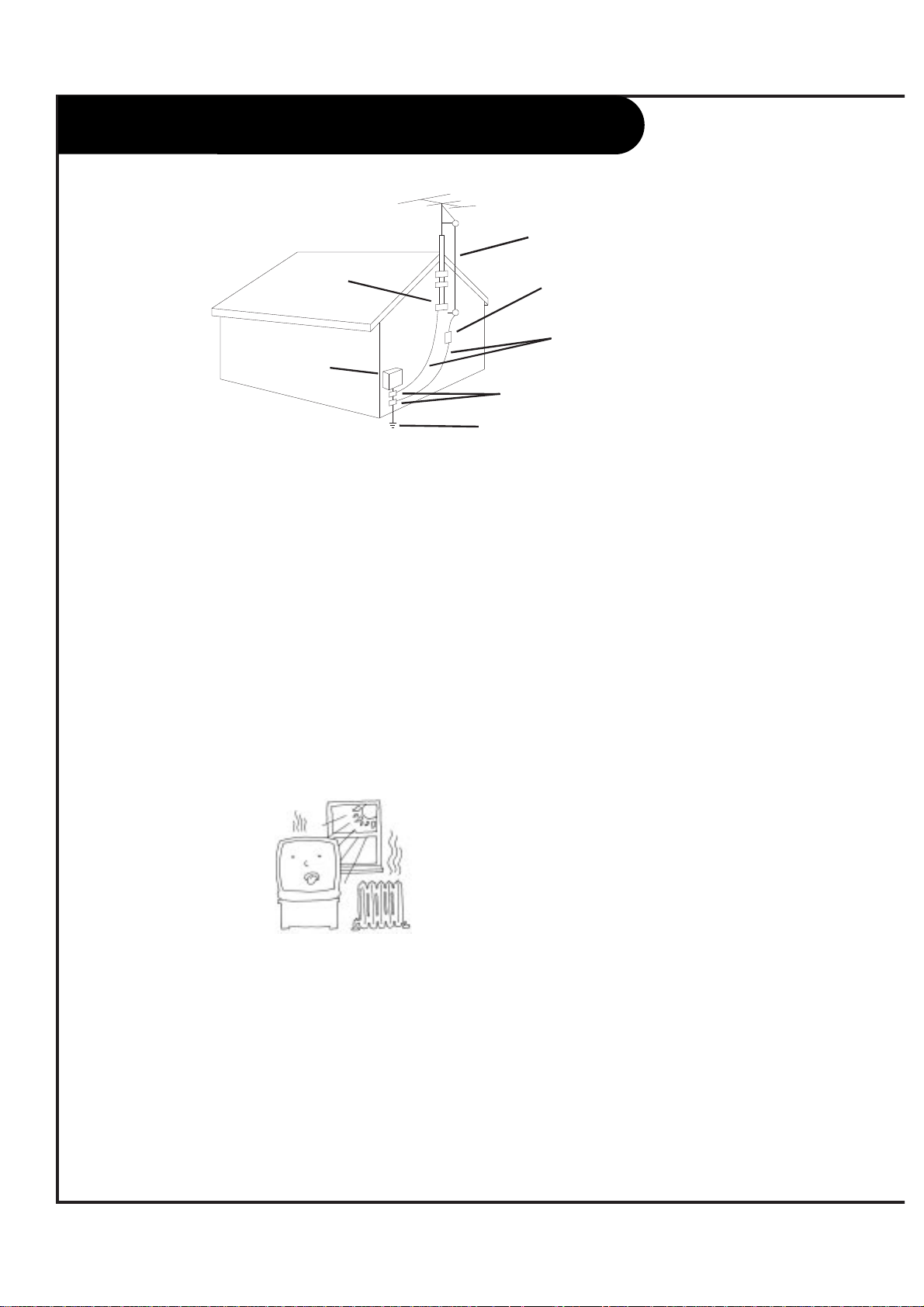
14. Outdoor Antenna Grounding
If an outside antenna or cable system is connected to
this product, be sure the antenna or cable system is
grounded so as to provide some protection against
voltage surges and built-up static charges. Article 810
of the National Electrical Code (USA), ANSI/NFPA 70,
provides information on grounding of the mast and
supporting structure, grounding of the lead-in wire to
an antenna discharge unit connection to the grounding electrodes, and requirements for the grounding
electrode. (See Fig. 1 on reverse side for an example).
15. Lightning
For added protection for this
product during a lightning
storm, or when product is left
unattended and unused for
long periods of time, unplug
it from the wall outlet and
disconnect antenna or cable
system. This will prevent damage to product due to lightning and power line surges.
P A GE 3
206-3533-O
IMPORTANT SAFETY INSTRUCTIONS
PORTABLE CART WARNING
Page 4
16. Power Lines
An outside antenna system should not be located in the
vicinity of overhead power lines or other electric light or
power circuits, or where it can fall into such power lines or
circuits. When installing an outside antenna system, take
extreme care to keep from touching such power lines or circuits, as contact with them might be fatal.
17. Overloading
Do not overload wall outlets, extension cords or integral
convenience receptacles, as this can result in risk of fire or
electric shoc
k.
18. Object and Liquid Entry
Never push objects of any kind into this product through
openings, as they may touch dangerous voltage points or
shortout parts that could result in fire or electric shock.
Never spill liquid of any kind on the product.
19. Heat
Keep product away from
heat sources such as
radiators, heat registers,
stoves, or other products (including amplifiers) that produce heat.
20. Wall or Ceiling Mounting
Mount a product to a wall or ceiling only as recommended
by the manufacturer.
21. Servicing
Do not attempt to service this product yourself, as opening or removing covers may expose you to dangerous voltage or other hazards. Refer all servicing to qualified service
personnel.
22. Damage Requiring Service
Unplug this product from the wall outlet and refer servicing
to qualified service personnel under these conditions:
a. If the power-supply cord or plug is damaged.
b. If liquid has been spilled or objects have fallen into
the product.
c. If the product has been exposed to rain or water.
d. If the product doesn’t operate normally by following the
operating guide. Adjust only those controls covered by
the operating guide; improper adjustment of other controls may result in damage and often requires extensive
work by a qualified technician to restore the product to
normal operation.
e. If the product has been dropped or cabinet has been
damaged.
f. If the product exhibits a distinct change in perfor-
mance.
23. Replacement Parts
When replacement part(s) are required, be sure service technician has used replacement part(s) specified by manufacturer or have same characteristics as original part(s).
Unauthorized substitutions may result in fire, electric shock,
or other hazards.
24. Safety Check
Upon completion of any service or repairs to this product,
ask service technician to perform safety checks to determine that product is in proper operating condition.
P A GE 4
206-3533-O
Antenna Lead-in Wire
Antenna Discharge Unit
NEC Section 810-20
Grounding Conductors
NEC Section 810-21
Ground Clamps
Power Service Grounding
Electrode System
NEC Art 250, Part H
Ground
Clamp
Electric Service
Equipment
IMPORTANT SAFETY INSTRUCTIONS
Page 5

Table of Contents
P A GE 5
206-3533-O
Safety Warnings . . . . . . . . . . . . . . . . . . . . . . . . . . . .2
Important Safety Information . . . . . . . . . . . . . . . . . . .3
Hookup Directory . . . . . . . . . . . . . . . . . . . . . . . . . . .6
Step 1. Hook Up TV
Rear Jack Panel . . . . . . . . . . . . . . . . . . . . . . . . . . . .6
Front Jack Panel . . . . . . . . . . . . . . . . . . . . . . . . . . .7
DTV Antenna Hookup . . . . . . . . . . . . . . . . . . . . . . .8-9
Cable Box . . . . . . . . . . . . . . . . . . . . . . . . . . . . .10-11
VCR and S-VHS VCR Hookup . . . . . . . . . . . . . . . . .12-13
DVD Hookup . . . . . . . . . . . . . . . . . . . . . . . . . . .14-15
DBS Satellite and VGA Hookup . . . . . . . . . . . . . . .16-17
External Stereo Hookup . . . . . . . . . . . . . . . . . . . . . .18
Dolby Digital Audio Hookup . . . . . . . . . . . . . . . . . . .19
Room Setups for Home Theater . . . . . . . . . . . . . . . . .20
Monitor Out . . . . . . . . . . . . . . . . . . . . . . . . . . . . . .21
Remote Button Functions . . . . . . . . . . . . . . . . . . .22-23
On-Screen Display . . . . . . . . . . . . . . . . . . . . . . . . . .24
Front Panel Controls . . . . . . . . . . . . . . . . . . . . . . . .25
Step 2. Channel Search and Reception Setup
EZ Scan Setup . . . . . . . . . . . . . . . . . . . . . . . . . . . . 26
Digital TV Antenna Tune . . . . . . . . . . . . . . . . . . . . . .27
Step 3. Customize your TV’s Features
Setup Menu
Channel Add/Delete/Surf . . . . . . . . . . . . . . . . . . . . .28
Channel Labels . . . . . . . . . . . . . . . . . . . . . . . . . . . .29
Screen Source . . . . . . . . . . . . . . . . . . . . . . . . . . . .30
Digital VCR Mode . . . . . . . . . . . . . . . . . . . . . . . . . .31
EZ Focus . . . . . . . . . . . . . . . . . . . . . . . . . . . . . . . .32
Guide Plus . . . . . . . . . . . . . . . . . . . . . . . . . . . .33-38
Video Menu . . . . . . . . . . . . . . . . . . . . . . . . . . . . .39
Audio Menu . . . . . . . . . . . . . . . . . . . . . . . . . . . . .40
Special Menu
Aspect Ratio . . . . . . . . . . . . . . . . . . . . . . . . . . . . .41
PIP Size . . . . . . . . . . . . . . . . . . . . . . . . . . . . . . . .42
Language . . . . . . . . . . . . . . . . . . . . . . . . . . . . . . .43
Captions/Text . . . . . . . . . . . . . . . . . . . . . . . . . . . .44
EZ Demo . . . . . . . . . . . . . . . . . . . . . . . . . . . . . . . .45
Clock Menu
Clock Set . . . . . . . . . . . . . . . . . . . . . . . . . . . . . . .46
EZ Timer . . . . . . . . . . . . . . . . . . . . . . . . . . . . . . . .47
Daylight Savings . . . . . . . . . . . . . . . . . . . . . . . . . . .48
Time Zone . . . . . . . . . . . . . . . . . . . . . . . . . . . . . . .49
Lock Menu
Parental Lock . . . . . . . . . . . . . . . . . . . . . . . . . .50-51
Remote Control Programming . . . . . . . . . . . . . . . . . .52
Remote Control Auto-Search . . . . . . . . . . . . . . . . . . .53
Remote Control Auto-Find . . . . . . . . . . . . . . . . . . . .54
Multi-Commands Memory Buttons . . . . . . . . . . . . . . . .55
More Mode Functions . . . . . . . . . . . . . . . . . . . . . . . .56
TV and VCR “Punch-Through” Controls . . . . . . . . . . . . .57
Programming Codes . . . . . . . . . . . . . . . . . . . . . .58-62
Maintenance . . . . . . . . . . . . . . . . . . . . . . . . . . .63-64
Troubleshooting . . . . . . . . . . . . . . . . . . . . . . . . .65-66
Glossary . . . . . . . . . . . . . . . . . . . . . . . . . . . . . .67-68
Product Specifications . . . . . . . . . . . . . . . . . . . . . .69
Note: Design and specifications are subject to change without prior notice.
Page 6
Mini glossary
JACK A connection on the back of a TV, VCR, or any other A/V device. This includes the RF jack and the Audio/Video jacks that are color-
coded.
SIGNAL Picture and sound traveling through cable, or on the air, to your television screen.
P A GE 6
206-3533-O
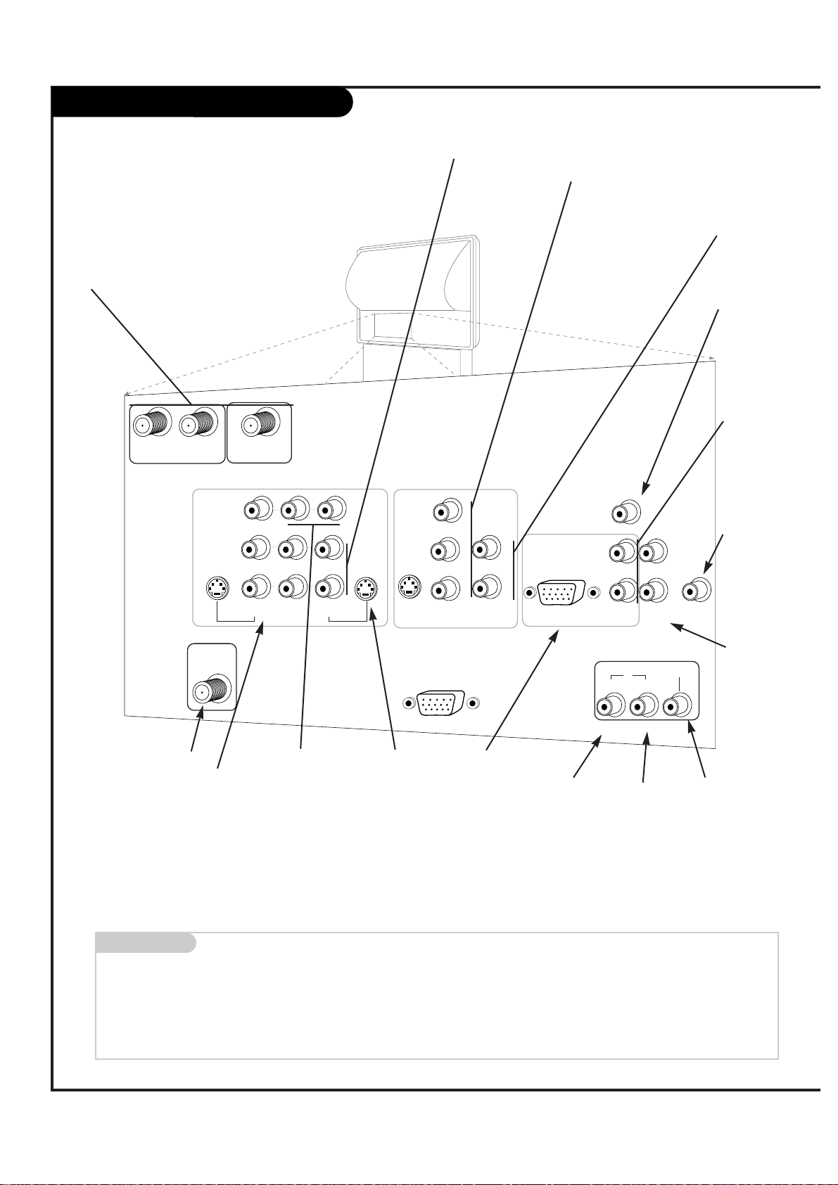
Rear Audio/Video Jacks
VIDEO 2
INPUT
VIDEO 1
INPUT
S-VIDEO
IN
MONITOR
OUT
Y
PB
PR
DVD/HI RES
COMP VIDEO IN
ANT/CABLE2
INPUT
ANT/CABLE1
INPUT
DTV/RF
ANTENNA
INPUT
R
L
R
L
R
L
S-VIDEO
OUT
CALIBRATION
S-VIDEO
IN
AUDIO
IN
VIDEO
(MONO) (MONO)
VIDEO
LOOP OUT
VARIABLE
AUDIO OUT
DOLBY DIGITAL
AUDIO
CENTER MODE
IN
R
L
R
L
HD DBS/VGA IN
(R, G, B, Sync)
AUDIO
IN
G-LINK
IN
DVD
/ HI RES
HD DBS
/ VGA
OUT
S-VIDEO In
A connection
available with
some high-end
equipment that
provides even
better picture
quality for
Video 1.
Variable Out
Used to connect
either an external amplifier, or
add a subwoofer to your
surround sound
system.
RF Connectors: Antenna/Cable 1,
Antenna/Cable 2, and Loop Out
Used to connect analog cable or
antenna signals to the television,
either directly or through your cable
box.
Left/Right Audio
Used for stereo sound
from various types of
equipment.
Video 1 or 2
Connects the
video signals from
various types of
equipment.
Y, Pb, Pr
DVD Component Video
and HD Component
Video
Some top-of-the-line DVD
players use what is
called “component video,”
for extremely accurate
picture reproduction.
Refer to your DVD manual
for further information.
Connecting cables to your Entertainment Machine.
RF Connectors: Digital TV
Input
Used to connect antenna signals to the television.
Note: A signal splitter will be
necessary if you plan to use
your antenna for both digital
and analog reception.
Monitor Out
Connects to a
second TV or
Monitor.
Left/Right Audio
Used for stereo
sound from various
types of equipment.
Dolby Digital Out
Connects to a Dolby
Digital A/V receiver.
VGA and DBS
Input
Used to connect
from an VGA
source or DBS
Satellite system.
G-Link:
Used for connecting to
Gemstar equipment.
Dolby
Digital In
Connects to
a Dolby
Digital
output from
DVD or HiRes component
.
Dolby
Digital In
Connects to
a Dolby
Digital
output from HD
DBS system
.
Center Mode In
Connect to external
Dolby Digital Center
“preamp output.”
VGA and DBS
Audio Input
Used in audio
connections for
VGA and DBS
input.
Page 7
P A GE 7
206-3533-O
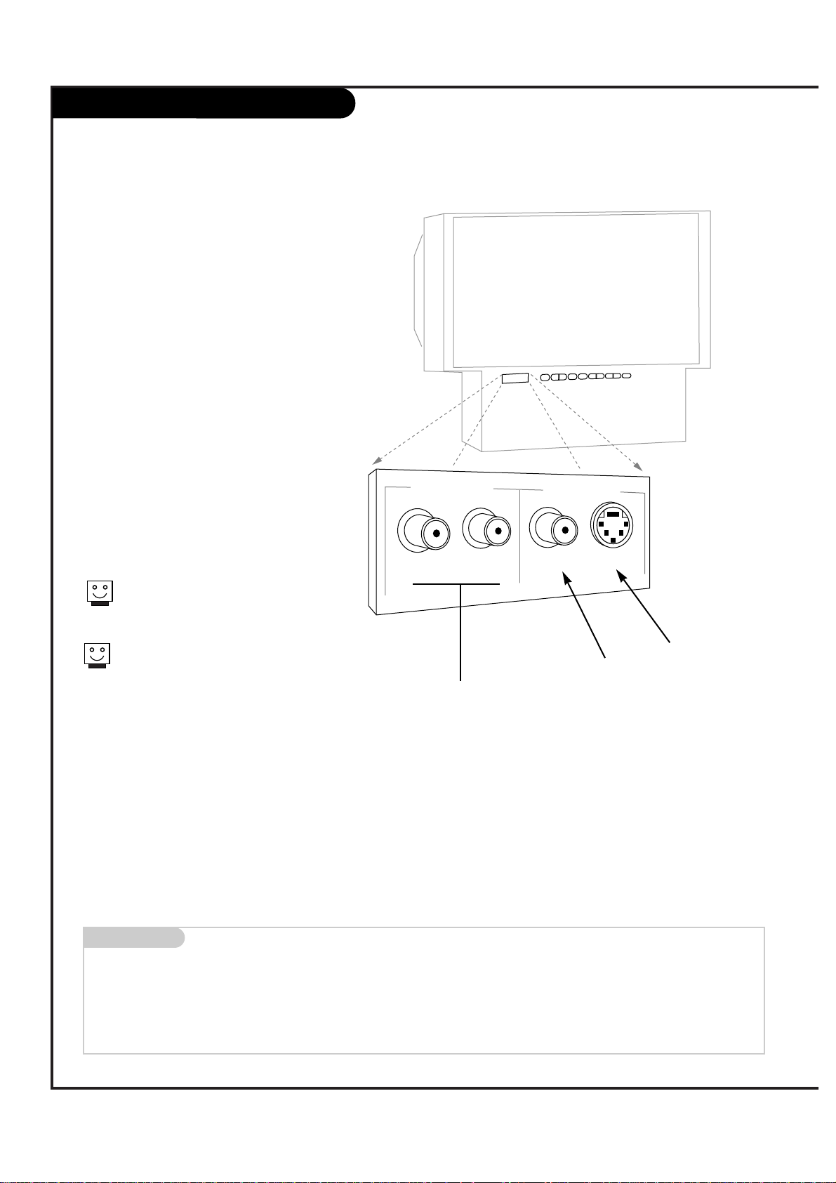
Front Audio/Video Jacks
s-video
video
right
left
front audio input
front video input
Front A/V Panel
There are four jacks on the front of
your Entertainment Machine that make
connecting Audio/Video devices like video
games and camcorders very simple.
The jacks are located behind a small door
beside the buttons on the front panel.
The jacks are like those found in the jack
pack on the back of your Entertainment
Machine. This means that most equipment
that connects to those types of jacks in
the rear jack pack, can also be connected
in front.
To use the front jacks as the signal source,
use the Screen Source menu as described
on page 30. They will be named “Front
Video” in the Screen Source menu.
Left/Right Audio
Used for stereo sound
from various types of
equipment.
Video
Connects the video
signals from any
piece of equipment.
S-Video
A feature available
with some very
high-end equipment
that provides even
better picture quality.
When you choose Front Video
or Front S-Video, the audio is
automatically changed as well.
If you’re connecting a video game
unit, make sure to change the
picture settings with the Video
Preset option in the Video menu
(see page 38).
Mini glossary
A/V CABLES Audio/Video cables. Three cable connectors—Right audio (red), Left audio (white), and Video (yellow). A/V cables are used for stereo
playback of videocassettes and for higher quality picture and sound from other A/V devices.
A/V DEVICE Any device that produces video or sound (VCR, DVD, cable box, or television).
Page 8
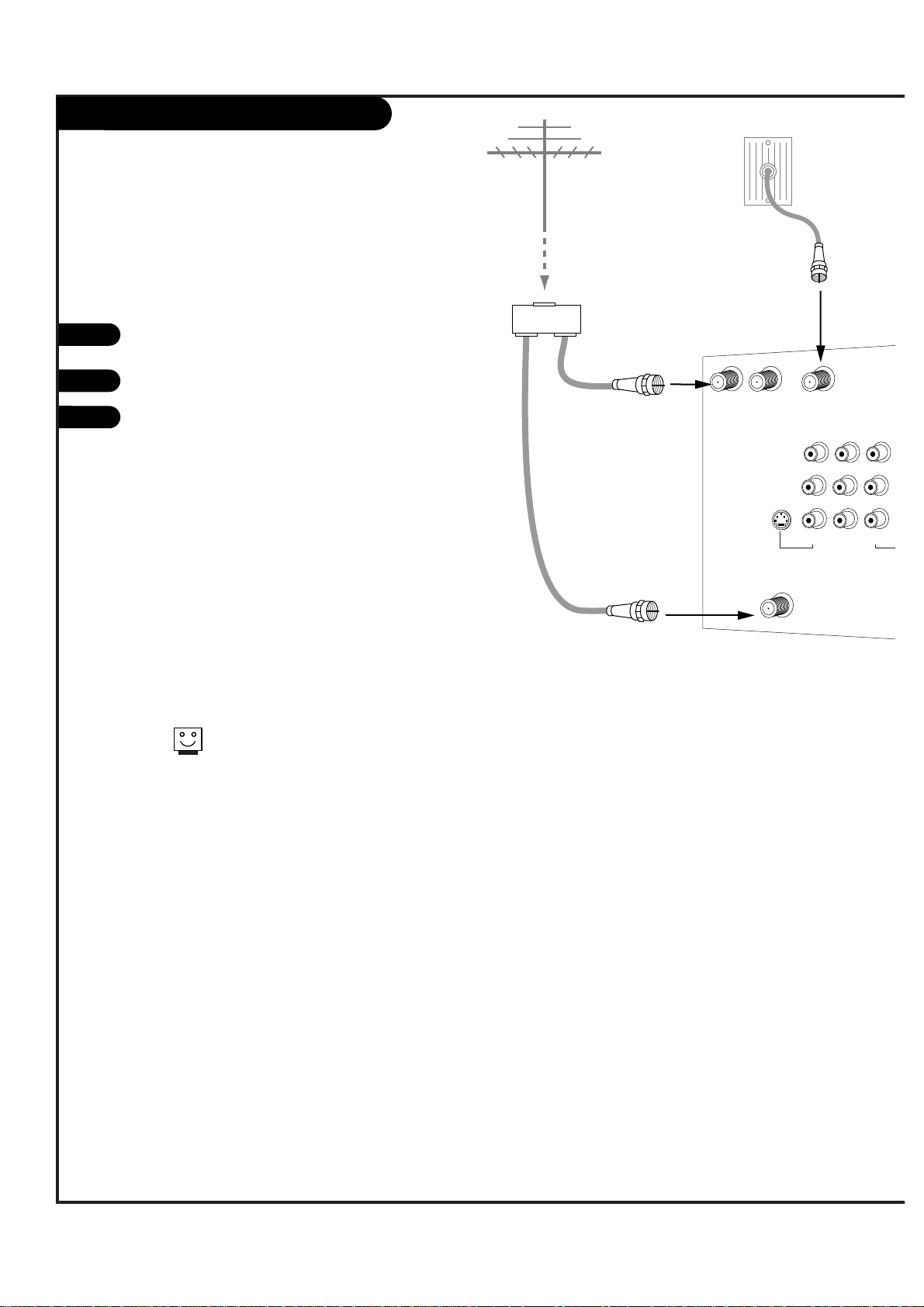
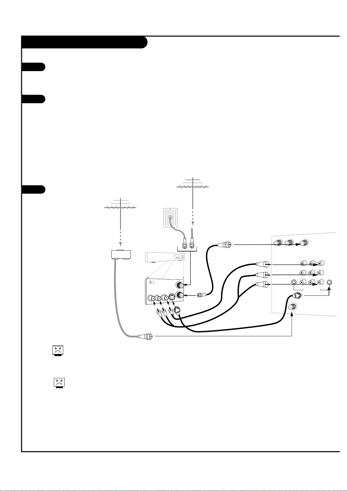
DTV Antenna Hookup
P A GE 8
206-3533-O
RF coaxial wire
(75ohm)
Antenna
Signal Splitter
RF coaxial wire
(75ohm)
Cable TV
wall jack
RF coaxial wire
(75ohm)
ANT/CABLE2
INPUT
ANT/CABLE1
INPUT
LOOP OUT
VIDEO 2
INPUT
VIDEO 1
INPUT
MONITOR
OUT
DTV/RF
ANTENNA
INPUT
R
L
R
L
S-VIDEO
OUT
V
(MONO) (MONO)
VIDEO
1
Connect the Entertainment Machine to your
ATSC (DTV) compatible antenna as shown.
Turn to page 27 to tune your DTV antenna.
Turn to pages 26-27 to activate EZ Program
for your analog signal and to tune your DTV
antenna.
For best performance, have your Antenna professionally adjusted.
2
If you receive your RF signal
through an antenna that is several
years old and connects with two
small prongs, you will need to purchase a 300 to 75 Ohm adapter. It
should be available from your local
electronics dealer.
Zenith recommends using a 75
ohm cable for your antenna connections in order to prevent interference.
If you wish to use your antenna to
receive both analog and digital
signals, you will need to purchase
a signal splitter. Please see onscreen setup guide on the following page.
3
Page 9
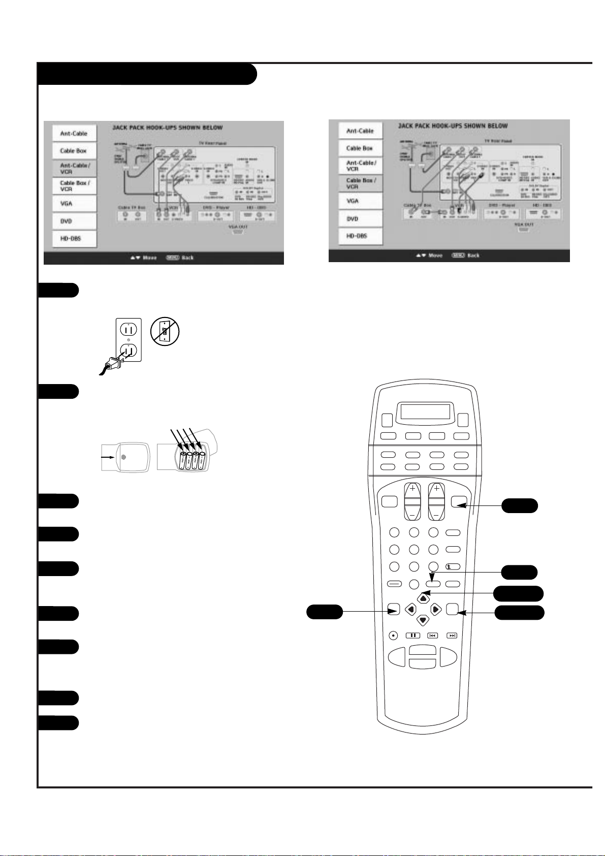
DTV Antenna Hookup (On-Screen Guide)
P A GE 9
206-3533-O
For best performance, have your Antenna professionally adjusted.
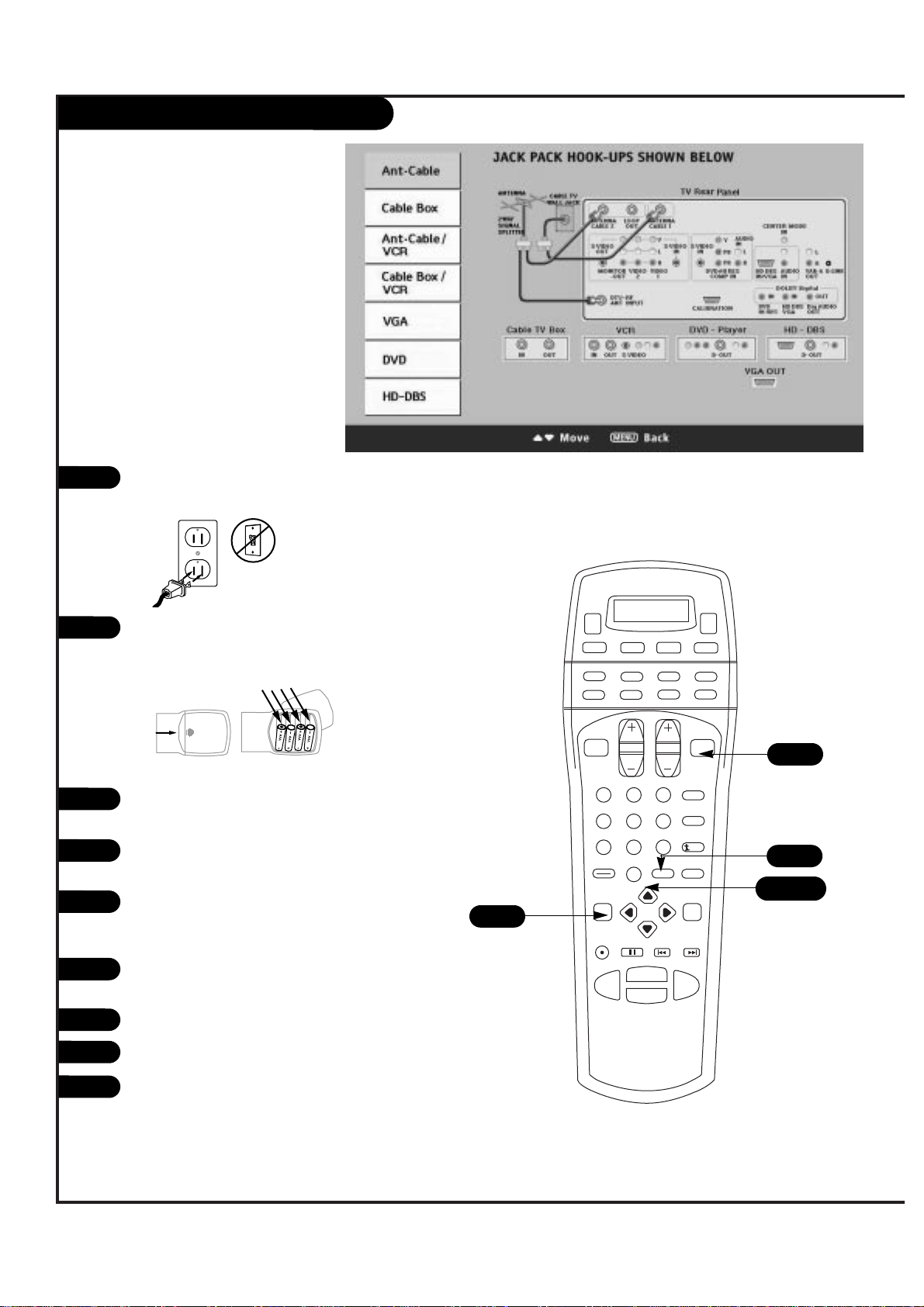
1
2
Plug in your Entertainment Machine into a 120V
60Hz outlet.
Remove the back of the remote and put in four
AAA batteries. Make sure batteries are properly
installed (check the +/– signs).
With the remote control in hand, press the POWER
button to turn on your Entertainment Machine.
Press the MENU key so the Setup menu appears,
and then press ENTER.
Using the UP/DOWN arrow on the remote control,
select EZ Program on your screen and then press
ENTER.
Press UP/DOWN button to select EZ Hookup, then
press ENTER.
Make your connections according to the diagram.
Press QUIT to exit the diagram.
Turn to pages 26-27 to activate EZ Scan for your
analog signal and to tune your DTV antenna.
3
4
5
6
7
8
back of
remote
1 2 3
4 5 6
7 8 9
0
record
pause
chapter chapter
play
stop
rewind
fast fwd
menu
enter
quit
ratio
surf
flashbk
picture
powermute
guide
vcr +
info
video dvd
clear
vcr
cable
audio
aux
tv sat
vol
ch
pg up
pg dwn
antenna dbs
4
5/6
3
8
9
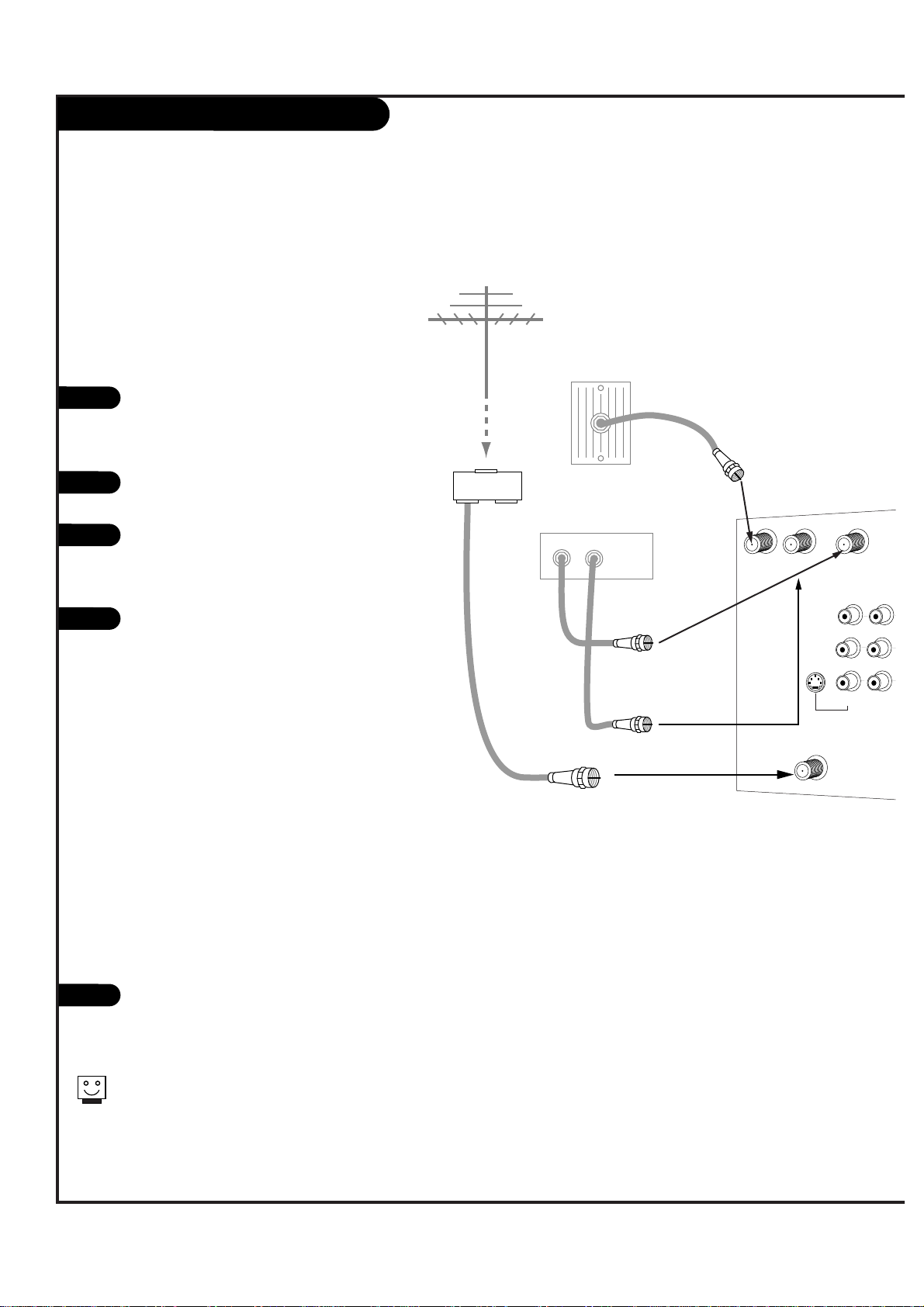
Page 10
Antenna
RF coaxial wire
(75ohm)
Rf coaxial wire
(75ohm)
Cable box
In
Out
Cable TV
wall jack
Signal Splitter
VIDEO 2
INPUT
MONITOR
OUT
ANT/CABLE2
INPUT
ANT/CABLE1
INPUT
DTV/RF
ANTENNA
INPUT
R
L
S-VIDEO
OUT
(MONO)
VIDEO
LOOP OUT
Cable Box
Locate the Antenna/Cable 2 jack on the
back of your TV. Connect the cable that
runs from the wall directly to the jack.
Now find the the Loop Out jack.
Connect the cable from this jack to the
Input jack on the back of your cable box.
Locate the Output jack on the back of
your cable box. Connect this to the
Antenna/Cable 1 jack on the back of your
TV.
To view the premium stations, set the
channel number on your cable box to
HBO, CINEMAX, SHOWTIME, etc. Then
press the Antenna button on your remote
and select the other Cable source
(Ant/Cable 1).
To view the non premium channels press
the Antenna button and select Ant/Cable 2.
Then run Auto Program to check for all
available channels and store them in
memory.
This can be combined with any other
equipment you may want
to hook up. Hook cable directly into the
TV, then to the cable box. From there, the
cable box goes to the next device, down
the line, until the last piece, which connects back to the TV in the
Antenna/Cable 1 jack.
Turn to pages 26-27 to activate EZ
Program for your analog signal and to
tune your DTV antenna.
1
2
3
4
Some cable services require the use of a cable box to decode premium channels and pay-per-view. Using the Loop Out to Decoder
option, and programming your remote, you can connect your cable
box so that you only need your MBR remote to control all the
channels. By connecting cable directly to your Entertainment
Machine, then running it out to the cable box and back, you make
the cable box another source to choose from in the Source selection on your remote.
To receive premium channels, run
Auto Program on the second source
that is set to receive channels.
P A GE 10
206-3533-O
5
Page 11
Cable Box (On-Screen Guide)
P A GE 11
206-3533-O
1 2 3
4 5 6
7 8 9
0
record
pause
chapter chapter
play
stop
rewind
fast fwd
menu
enter
quit
ratio
surf
flashbk
picture
powermute
guide
vcr +
info
video dvd
clear
vcr
cable
audio
aux
tv sat
vol
ch
pg up
pg dwn
antenna dbs
4
5/6
7
3
8
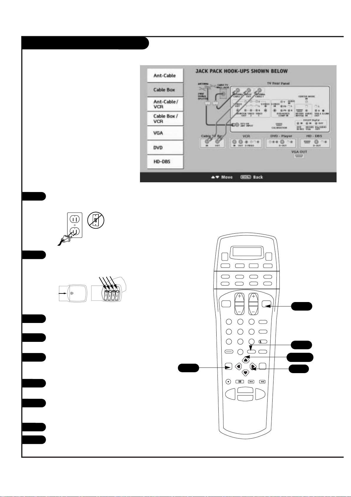
1
2
Plug in your Entertainment Machine into a 120V 60Hz
outlet.
Remove the back of the remote and put in four AAA
batteries. Make sure batteries are properly installed
(check the +/– signs).
With the remote control in hand, press the POWER
button to turn on your Entertainment Machine.
Press the MENU button so the Setup menu appears,
and then press ENTER.
Using the UP/DOWN arrow on the remote control,
select EZ Program on your screen and then press
ENTER.
Press UP/DOWN button to select EZ Hookup, then
press ENTER.
Press an UP/DOWN arrow on the remote to view the
CABLE BOX diagram (as shown above) and make your
connections according to the diagram.
Press QUIT to exit the diagram.
Turn to pages 26-27 to activate EZ Program for your
analog signal and to tune your DTV antenna.
3
4
5
6
7
8
back of
remote
9
Page 12
P A GE 12
206-3533-O
In
Out
Audio
Video
3 4
VCR
Back AV panel
A/V cables
not included
with TV
Cable TV
wall jack
Round wire
(75ohm)
RF coaxial wire
(75ohm)
Antenna
S-Video
OR
Antenna
RF coaxial wire
(75ohm)
Signal Splitter
VIDEO 2
INPUT
VIDEO 1
INPUT
S-VIDEO
IN
MONITOR
OUT
ANT/CABLE2
INPUT
ANT/CABLE1
INPUT
DTV/RF
ANTENNA
INPUT
R
L
R
L
S-VIDEO
OUT
VIDEO
(MONO)
(MONO)
VIDEO
LOOP OUT
1
2
VCR
Locate the RF or VHF/UHF/CATV In jack on
the back of your VCR. Connect the cable
line coming from your wall directly to
this jack.
Find the composite video and audio
jacks on the back of your VCR, and connect them following the instructions
provided with your equipment.
You may connect either the composite
video or the S-Video cables to your
Entertainment Machine. (Do not connect BOTH the composite and the SVideo cables. In the event that you
connect both composite and the SVideo cables, only the S-Video will
work.)
Turn to pages 26-27 to activate EZ
Program for your analog signal and to
tune your DTV antenna.
To hear stereo sound from cable or your VCR,
you will need to connect A/V cables as well as
the wire that runs from the VCR to your
Entertainment Machine.
If you want to receive your signals on Channel
3 or 4, locate the Out to TV jack on your VCR.
Connect a cable from the Out to TV jack to the
Antenna/Cable 1 jack on the back of your
Entertainment Machine.
3
Page 13
VCR (On-Screen Guide)
P A GE 13
206-3533-O
1 2 3
4 5 6
7 8 9
0
record
pause
chapter chapter
play
stop
rewind
fast fwd
menu
enter
quit
ratio
surf
flashbk
picture
powermute
guide
vcr +
info
video dvd
clear
vcr
cable
audio
aux
tv sat
vol
ch
pg up
pg dwn
antenna dbs
4
5/6/7
4/5/6
3
8
1
2
Plug in your Entertainment Machine into a 120V 60Hz
outlet.
Remove the back of the remote and put in four AAA
batteries. Make sure batteries are properly installed
(check the +/– signs).
With the remote control in hand, press the POWER
button to turn on your Entertainment Machine.
Press the MENU button so the Setup menu appears,
and then press ENTER.
Using the UP/DOWN arrow on the remote control,
select EZ Program on your screen and then press
ENTER.
Press UP/DOWN button to select EZ Hookup, then
press ENTER.
Press an UP/DOWN arrow on the remote to view the
ANT-CABLE/VCR or CABLE BOX/VCR diagram (as shown
above) and make your connections according to the
diagrams.
Press QUIT to exit the diagram.
Turn to pages 26-27 to activate EZ Program for your
analog signal and to tune your DTV antenna.
3
4
5
6
7
8
back of
remote
9
Page 14
P A GE 14
206-3533-O
Mini glossary
COMPONENT VIDEO Some video equipment uses three separate lines (Y, Pb, Pr) to more precisely reproduce images. Your manual will explain how
this relates to your equipment.
B
O
A
U
E
D
N
I
DVD Player
Find the audio and composite or
S-Video jacks on the back of your
DVD Player and connect them following the instructions provided
with your equipment.
You may connect either the composite video or the S-Video cables
to your Entertainment Machine.
Do not connect both the composite and the S-Video.
1
2
Some high-end DVD players use
a picture reproduction system
called “component video.” If
your DVD player has component
output, use the connectors
marked “DVD” on the jack
panel. Please refer to your DVD
manual for proper installation.
DVD Player
Back AV panel
Dolby Digital
Audio
Out
L R
DVD Player
Back AV panel
ANT/CABLE2
INPUT
S-Video
A/V cables
not included
with TV
OR
LOOP OUT
DTV/RF
ANTENNA
INPUT
S-VIDEO
ANT/CABLE1
INPUT
AUDIO
CENTER MODE
/ HI RES
IN
L
R
VARIA
AUDIO
IN
AUDIO
DOLBY DIGIT
IN
DVD
HD DBS
/ VGA
S-VIDEO
Y
L
PB
S-VIDEO
IN
IN
PR
DVD/HI RES
COMP VIDEO IN
CALIBRATION
R
(R, G, B, Sync)
AUDIO
HD DBS/VGA IN
IN
VIDEO 2
VIDEO
L
(MONO) (MONO)
R
VIDEO 1
INPUT
INPUT
VIDEO
L
OUT
R
MONITOR
OUT
Audio
L R
A/V cables
not included
with TV
Dolby Digital
Out
OR
Component Video
ANT/CABLE2
INPUT
LOOP OUT
DTV/RF
ANTENNA
INPUT
S-VIDEO
ANT/CABLE1
INPUT
S-VIDEO
Y
PB
S-VIDEO
IN
IN
PR
DVD/HI RES
COMP VIDEO IN
CALIBRATION
VIDEO 2
VIDEO
L
(MONO) (MONO)
R
VIDEO 1
INPUT
INPUT
VIDEO
L
OUT
R
MONITOR
OUT
Use shielded 75 Ω Video type cable
L
R
AUDIO
IN
(R, G, B, Sync)
HD DBS/VGA IN
L
R
/ HI RES
A
CENT
AU
I
DVD
Page 15
DVD Player (On-Screen Guide)
P A GE 15
206-3533-O
1 2 3
4 5 6
7 8 9
0
record
pause
chapter chapter
play
stop
rewind
fast fwd
menu
enter
quit
ratio
surf
flashbk
picture
powermute
guide
vcr +
info
video dvd
clear
vcr
cable
audio
aux
tv sat
vol
ch
pg up
pg dwn
antenna dbs
4
5/6/7
3
8
1
2
Plug in your Entertainment Machine into a 120V 60Hz
outlet.
Remove the back of the remote and put in four AAA
batteries. Make sure batteries are properly installed
(check the +/– signs).
With the remote control in hand, press the POWER
button to turn on your Entertainment Machine.
Press the MENU button so the Setup menu appears,
and then press ENTER.
Using the UP/DOWN arrow on the remote control,
select EZ Program on your screen and then press
ENTER.
Press UP/DOWN button to select EZ Hookup, then
press ENTER.
Press an UP/DOWN arrow on the remote to view the
DVD diagram (as shown above) and make your connections according to the diagram.
Press QUIT to exit the diagram.
3
4
5
6
7
8
back of
remote
4/5/6
Page 16
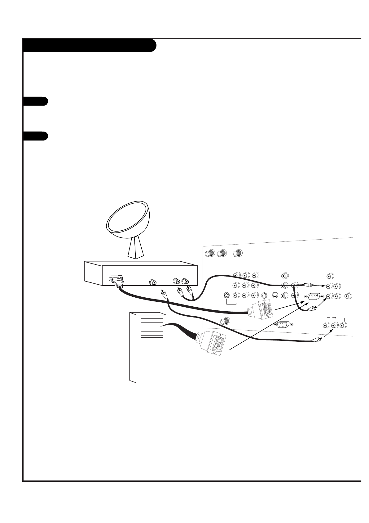
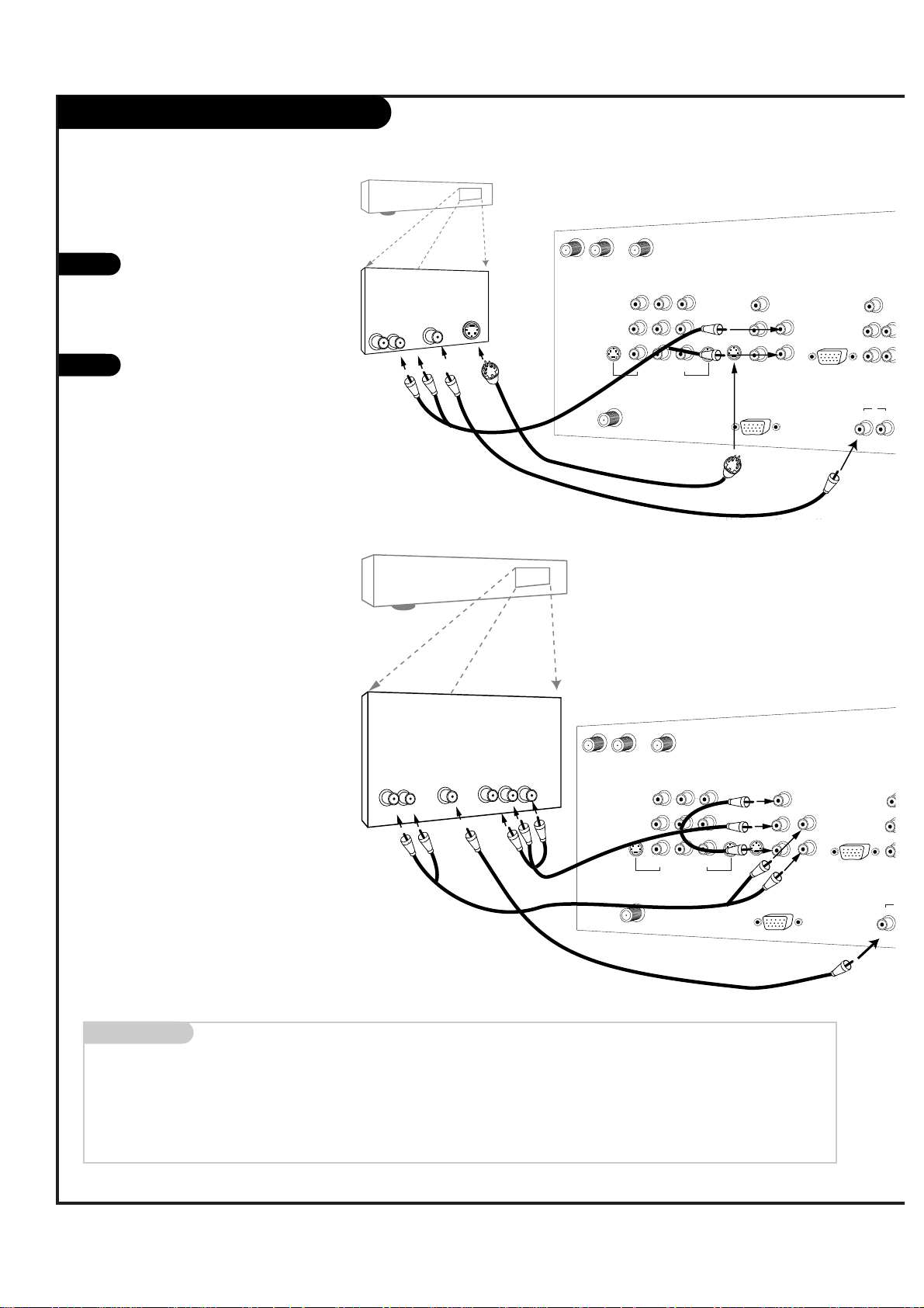
DBS and VGA Hookup
L
DBS Receiver
OR
Computer
Audio
L R
Dolby Digital
Out
Use shielded 75 Ω Video type cable
OR
CALIBRATION
ANT/CABLE2
INPUT
ANT/CABLE1
INPUT
LOOP OUT
VIDEO 2
INPUT
VIDEO 1
INPUT
S-VIDEO
IN
MONITOR
OUT
DTV/RF
ANTENNA
INPUT
R
L
R
L
S-VIDEO
OUT
VIDEO
(MONO) (MONO)
VIDEO
Y
PB
PR
DVD/HI RES
COMP VIDEO IN
R
S-VIDEO
IN
AUDIO
IN
VARIABLE
AUDIO OUT
DOLBY DIGITAL
AUDIO
CENTER MODE
IN
R
L
R
L
HD DBS/VGA IN
(R, G, B, Sync)
AUDIO
IN
G-LINK
IN
DVD
/ HI RES
HD DBS
/ VGA
OUT
Find the audio and VGA jacks on the back
of your DBS receiver (or Computer) and
connect them following the instructions
provided with your equipment.
Connect these cables to your Entertainment
Machine as shown.
1
2
P A GE 16
206-3533-O
Page 17
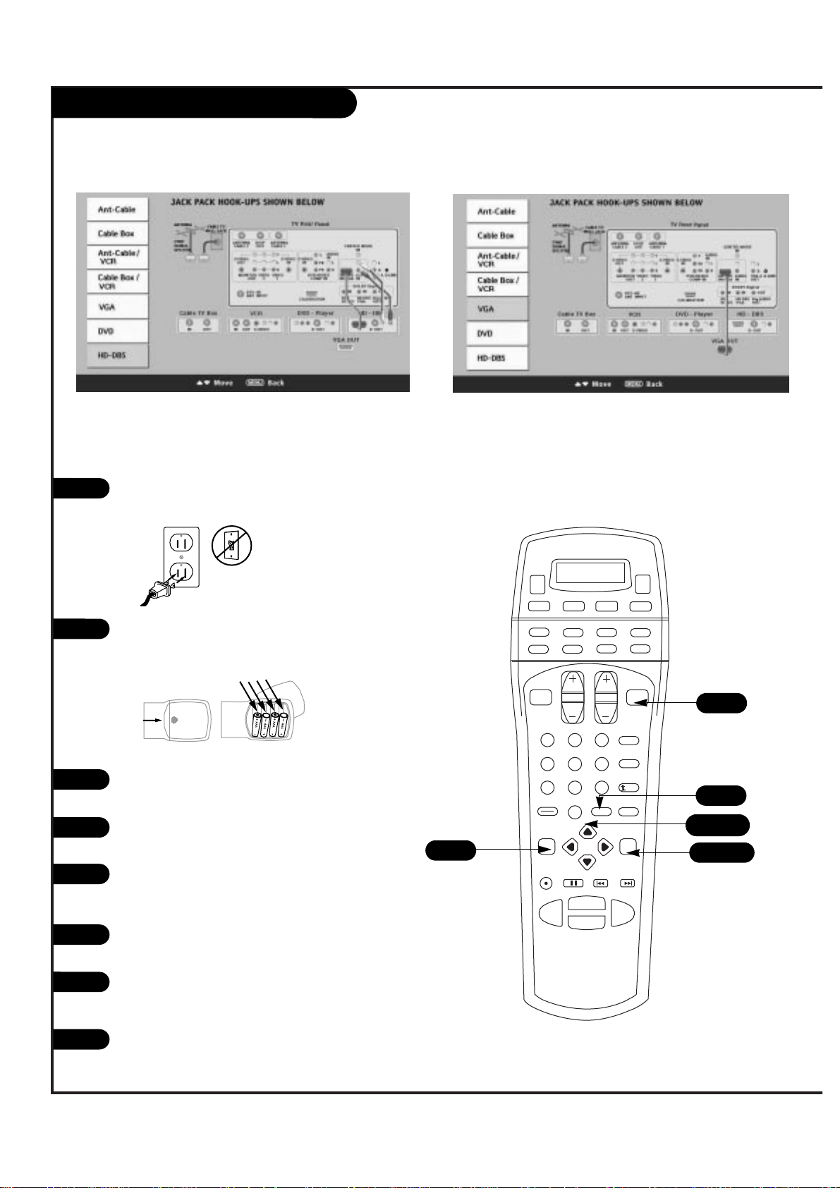
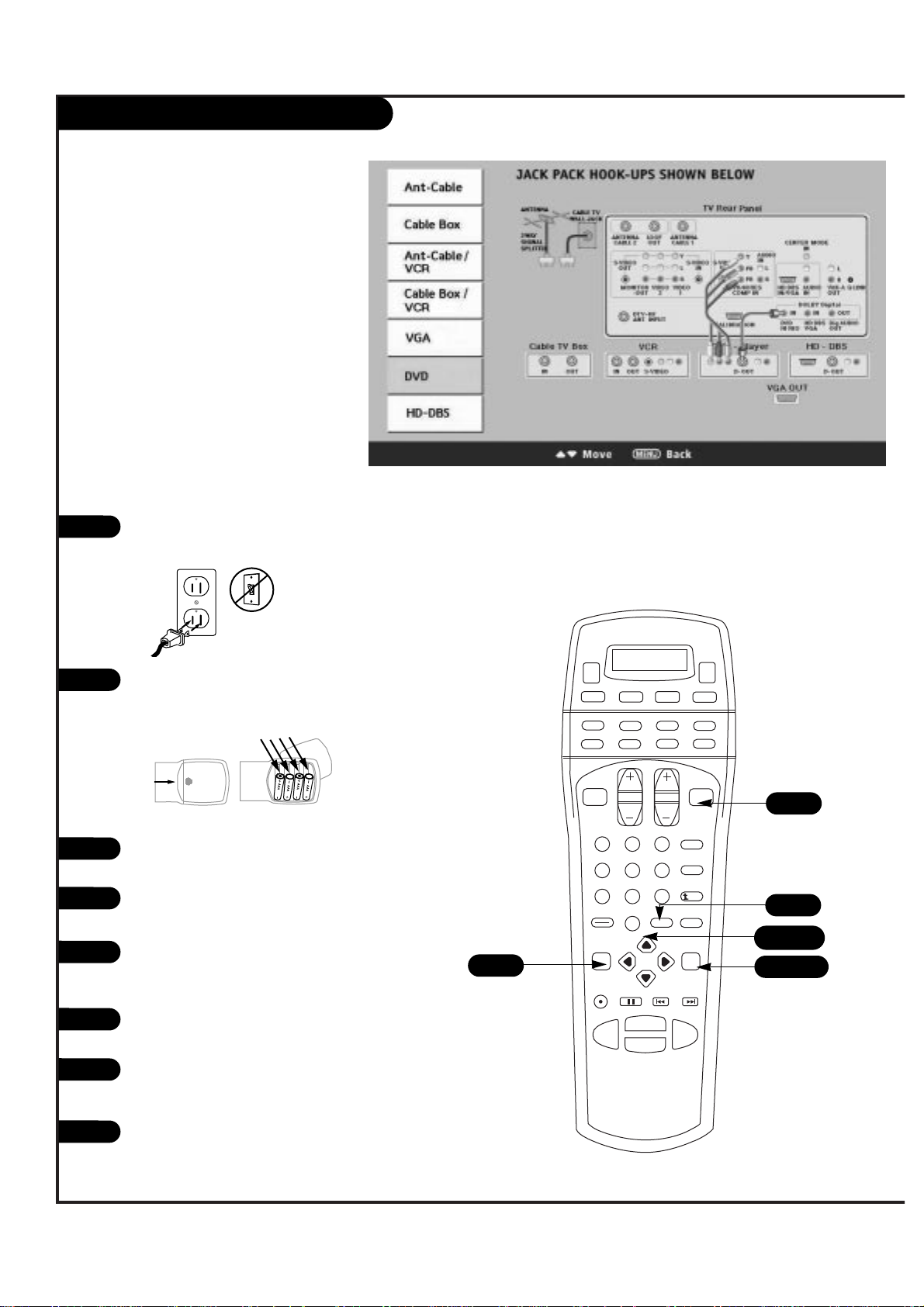
DBS and VGA Hookup (On-Screen Guide)
P A GE 17
206-3533-O
1 2 3
4 5 6
7 8 9
0
record
pause
chapter chapter
play
stop
rewind
fast fwd
menu
enter
quit
ratio
surf
flashbk
picture
powermute
guide
vcr +
info
video dvd
clear
vcr
cable
audio
aux
tv sat
vol
ch
pg up
pg dwn
antenna dbs
4
5/6
4/5/6
3
8
1
2
Plug in your Entertainment Machine into a 120V 60Hz
outlet.
Remove the back of the remote and put in four AAA
batteries. Make sure batteries are properly installed
(check the +/– signs).
With the remote control in hand, press the POWER
button to turn on your Entertainment Machine.
Press the MENU button so the Setup menu appears,
and then press ENTER.
Using the UP/DOWN arrow on the remote control,
select EZ Program on your screen and then press
ENTER.
Press UP/DOWN button to select EZ Hookup, then
press ENTER.
Press an UP/DOWN arrow on the remote to view the
HD-DBS or VGA diagrams (as shown above) and make
your connections according to the diagrams.
Press QUIT to exit the diagram.
3
4
5
6
7
8
back of
remote
Page 18
P A GE 18
206-3533-O
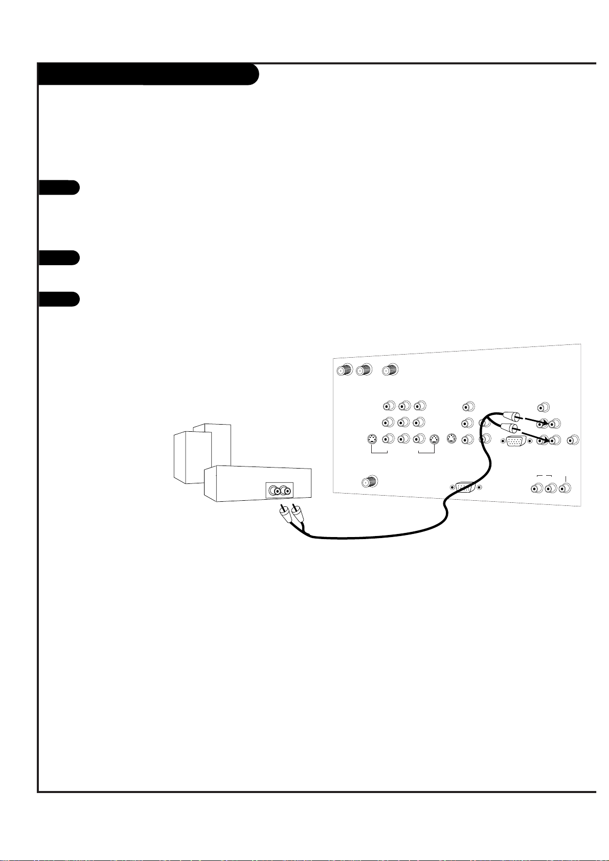
Analog stereo amplifier
Audio cables
not included
with TV
CALIBRATION
ANT/CABLE2
INPUT
ANT/CABLE1
INPUT
LOOP OUT
VIDEO 2
INPUT
VIDEO 1
INPUT
S-VIDEO
IN
MONITOR
OUT
DTV/RF
ANTENNA
INPUT
R
L
R
L
S-VIDEO
OUT
VIDEO
(MONO) (MONO)
VIDEO
Y
PB
PR
DVD/HI RES
COMP VIDEO IN
R
L
S-VIDEO
IN
AUDIO
IN
VARIABLE
AUDIO OUT
DOLBY DIGITAL
AUDIO
CENTER MODE
IN
R
L
R
L
HD DBS/VGA IN
(R, G, B, Sync)
AUDIO
IN
G-LINK
IN
DVD
/ HI RES
HD DBS
/ VGA
OUT
External Stereo
1
2
Locate the Variable Audio Out
jacks on the back of your
Entertainment Machine and the
Input jacks on the back of your
stereo's amplifier.
Connect the two jacks, making
sure that the right and left channels are placed correctly.
Set up your speakers through
your stereo, according to those
directions.
3
Hook up Left/Right Front Speaker to Amplifier System.
Page 19
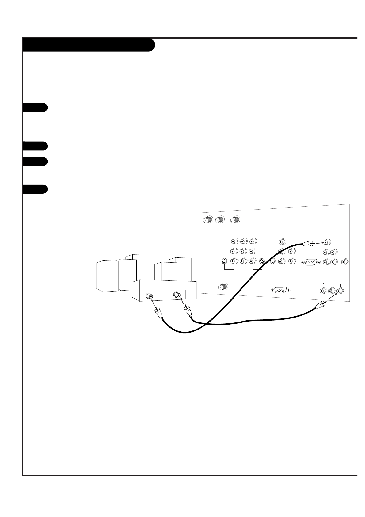
Dolby Digital Audio Hookup
P A GE 19
206-3533-O
Dolby Digital A/V Receiver
Use shielded 75 Ω Video type cable
Audio cables
not included
with TV
Center Channel
Preamp
Out
Front Left
Front Right
Rear Left
Surround
Rear Right
Surround
Dolby Digital
In
Powered
Subwoofer
CALIBRATION
ANT/CABLE2
INPUT
ANT/CABLE1
INPUT
LOOP OUT
VIDEO 2
INPUT
VIDEO 1
INPUT
S-VIDEO
IN
MONITOR
OUT
DTV/RF
ANTENNA
INPUT
R
L
R
L
S-VIDEO
OUT
VIDEO
(MONO) (MONO)
VIDEO
Y
PB
PR
DVD/HI RES
COMP VIDEO IN
R
L
S-VIDEO
IN
AUDIO
IN
VARIABLE
AUDIO OUT
DOLBY DIGITAL
AUDIO
CENTER MODE
IN
R
L
R
L
HD DBS/VGA IN
(R, G, B, Sync)
AUDIO
IN
G-LINK
IN
DVD
/ HI RES
HD DBS
/ VGA
OUT
1
2
Locate the Dolby Digital Output
jacks on the back of your
Entertainment Machine and the
Input jacks on the back of your
Dolby Digital Receiver.
Connect the two jacks, as shown.
Set up your Dolby Digital Receiver
according to the directions provided with that device.
If you wish to use your
Entertainment Machine as the
“center channel” for your Home
Theater, re-direct the center
channel into the special, “Center
Mode In” jack on your
Entertainment Machine.
3
4
Page 20
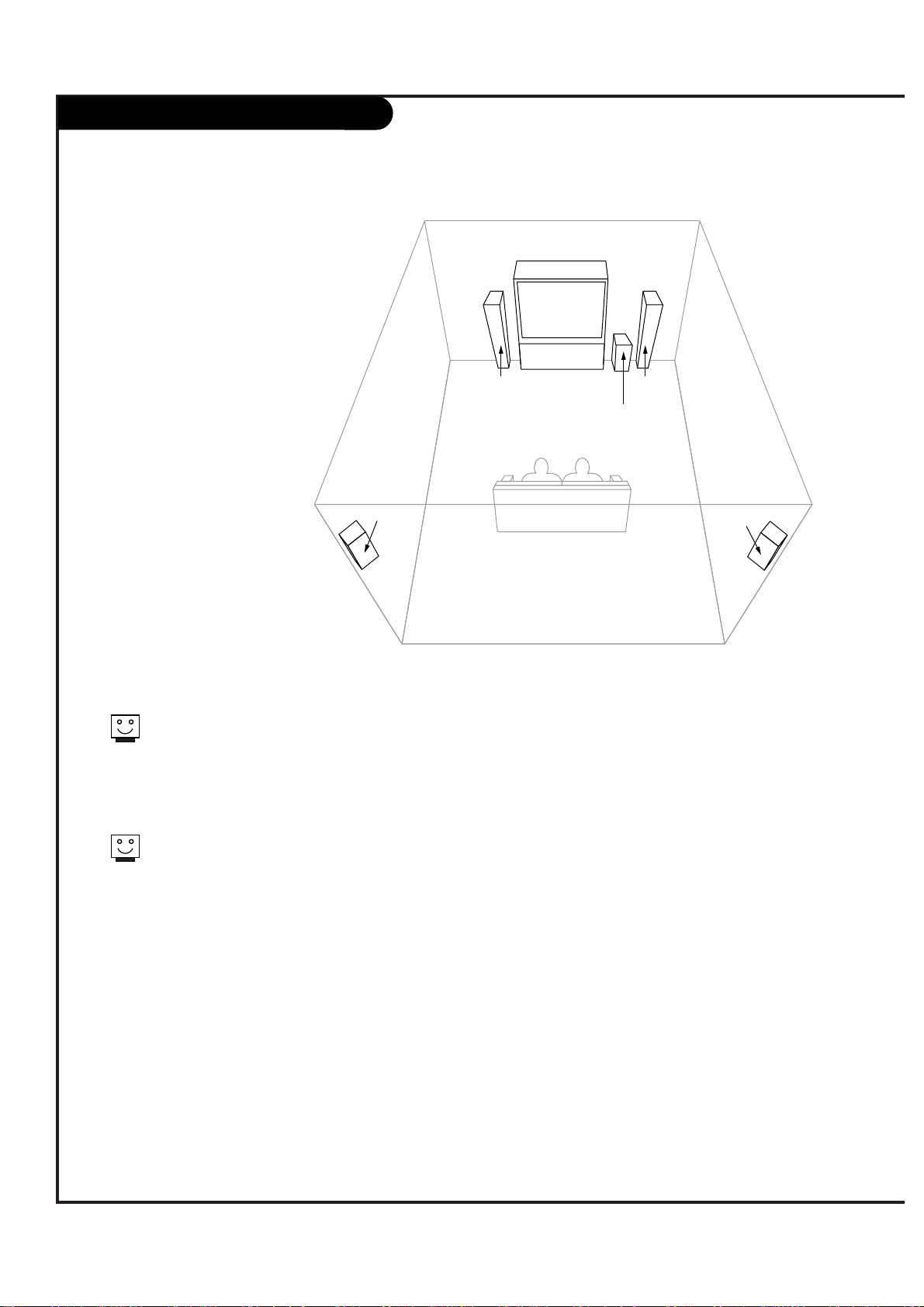
Room Setups for Home Theater
P A GE 20
206-3533-O
sub-woofer
right
speaker
left
speaker
surround
sound
speaker
surround
sound
speaker
This is just a general room design.
Any number of set-ups are possible,
and some changes may be needed
to maximize your sound. However, a
Dolby Digital Receiver is needed for
5.1 channel audio.
A left and right speaker on either
side of the set enhances separation.
The Entertainment Machine “center
mode in,” makes the dialog sound
as thought it’s coming directly from
the Entertainment Machine. The rear
surround sound speakers provide
the majority of other sounds, like
those from special effects in movies.
Your sub-woofer generates ultra-low
frequency sound, for rumbling
low-end audio.
Sound is affected by
speaker placement, so
make sure nothing is in
front of the speakers, and
that they are aimed in
appropriate directions.
You have the option of
turning on or off the internal
speakers.
Page 21
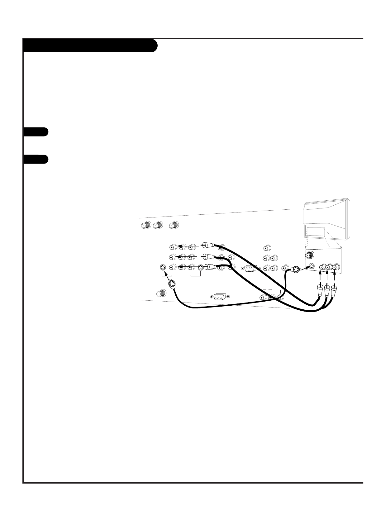
Monitor Out
P A GE 21
206-3533-O
Audio
Video
A/V cables
not included
with TV
Second TV
S-Video
CALIBRATION
ANT/CABLE2
INPUT
ANT/CABLE1
INPUT
LOOP OUT
VIDEO 2
INPUT
VIDEO 1
INPUT
S-VIDEO
IN
MONITOR
OUT
DTV/RF
ANTENNA
INPUT
R
L
R
L
S-VIDEO
OUT
VIDEO
(MONO) (MONO)
VIDEO
Y
PB
PR
DVD/HI RES
COMP VIDEO IN
R
L
S-VIDEO
IN
AUDIO
IN
VARIABLE
AUDIO OUT
DOLBY DIGITAL
AUDIO
CENTER MODE
IN
R
L
R
L
HD DBS/VGA IN
(R, G, B, Sync)
AUDIO
IN
G-LINK
IN
DVD
/ HI RES
HD DBS
/ VGA
OUT
Your Entertainment Machine has a special
feature which allows you to hook up a
second TV or monitor.
Just connect the second TV or monitor
using the OUT Audio/Video jacks located
on the back of your Entertainment
Machine. See the Operating Manual of the
second TV or monitor for further details
regarding that device’s input settings.
1
2
Page 22
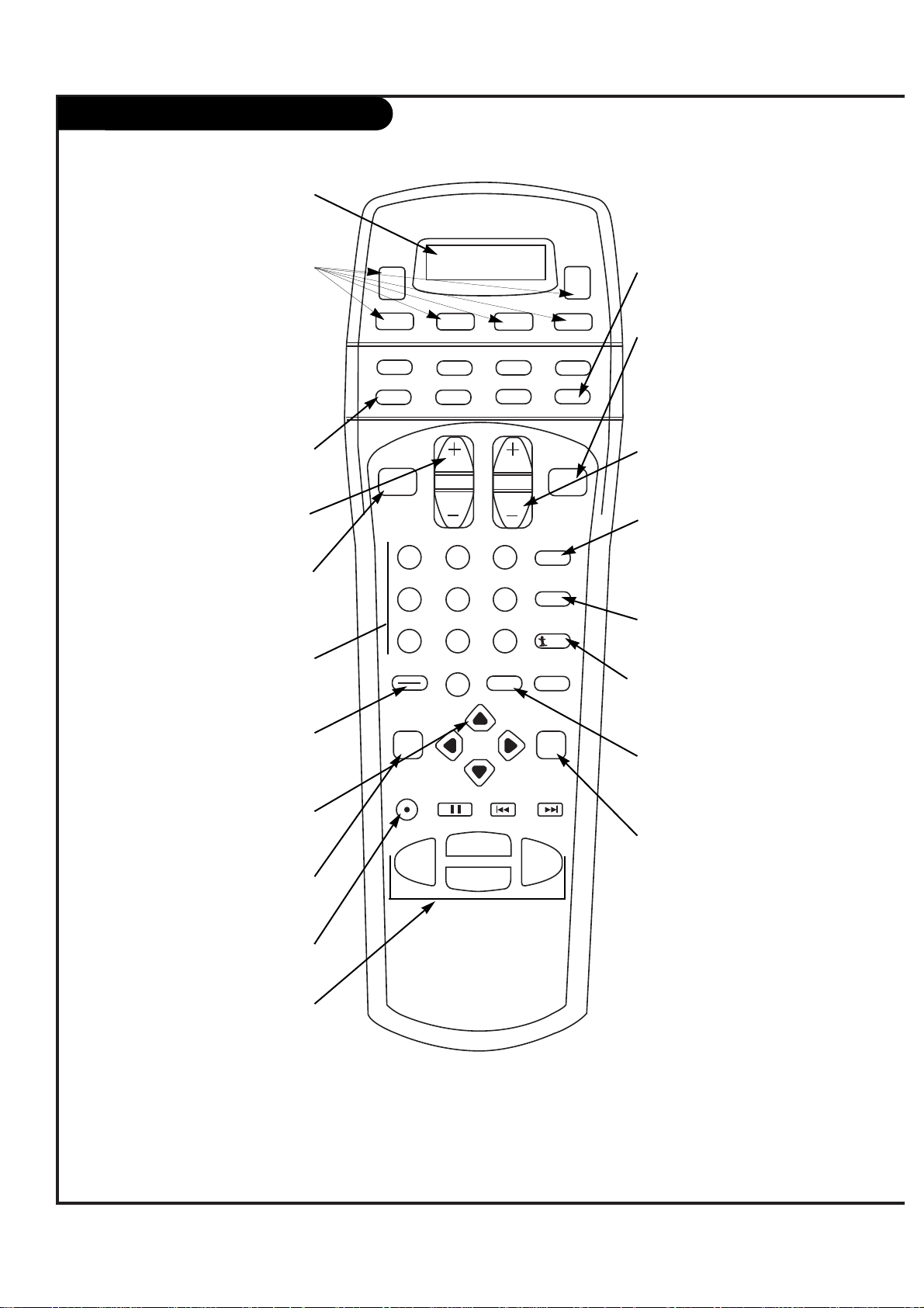
Button functions on your Remote
P A GE 22
206-3533-O
1 2 3
4 5 6
7 8 9
0
record
pause
chapter chapter
play
stop
rewind
fast fwd
menu
enter
quit
ratio
surf
flashbk
picture
powermute
guide
vcr +
info
video dvd
clear
vcr
cable
audio
aux
tv sat
vol
ch
pg up
pg dwn
antenna dbs
POWER
Turns your Entertainment
Machine or any other programmed equipment on or off,
depending on mode.
MODE BUTTONS
Select which mode your remote is
working in.
INDICATOR DISPLAY
LCD displays to show which mode
your remote is in.
CHANNEL UP/DOWN
Scroll through your available
channels.
NUMBER KEYPAD
For direct channel selection and
programming functions.
ENTER
Push to accept menu choices.
QUIT
Exits from most menu items.
RECORD, PAUSE
Control the functions on your VCR.
REW, FFWD, PLAY, STOP
Control the functions on your VCR.
MUTE
Switches the sound on or off.
SURF
Use the regular channel selection or your customized channel Surf lists.
VOLUME UP/DOWN
Increases/decreases the sound level.
PICTURE
This button automatically
brings up the Video Menu
(also used to adjust picture
settings as needed).
MENU
Displays on-screen menus.
ARROW KEYS
Allows you to move through
on-screen menu choices.
Remote Control Model Number
MBR3680Z
FLASHBK
Return immediately to the
last channel viewed.
ANTENNA
Selects Antenna/Cable as the picture
source.
“DASH” BUTTON
Used in entering program numbers for
multiple program channels such as
2—1.
*A digital broadcaster can transmit multiple programs on a single channel. These programs are
distinguished by a unique “sub-channel” number, separated when entering digits by the DASH
button on the remote.
HD-DBS/VGA
Selects HD-DBS or VGA as the
picture source.
Page 23

Button Functions on your Remote (con’t)
P A GE 23
206-3533-O
tune
timer
swap
move
pip +
pip -
pip
1 2 3
4 5 6
7 8 9
0
record
pause
chapter chapter
play
stop
rewind
fast fwd
menu
enter
quit
ratio
surf
flashbk
picture
powermute
guide
vcr +
info
video dvd
clear
vcr
cable
audio
aux
tv sat
vol
ch
pg up
pg dwn
antenna dbs
freez
MOVE
Moves the PIP window on your
screen.
PIP-/PIP+
Scroll through available channels
through the PIP window.
PIP
Activates the
PIP screen.
FREEZ
Freezes the
PIP image.
TUNE
Show the signal strength
of your DTV.
SWAP
Swaps the signal from
your PIP window to the
Main screen.
TIMER
Activates Sleep Timer options.
Page 24

On-Screen Display
This page describes your on-screen display options.
DOLBY DIGITAL
D
20-1Main PiP
10
A
20-0
03:00
Audio Mode:
Displays current audio mode.
Signal Mode:
Displays current signal mode,
either “A” for analog or “D”
for digital.
Channel Display:
Displays current channel. If you are
in a digital channel, then the “subchannel” is listed on the right side of
the dash.
Channel Label:
If channel label has been set, then it
will appear here.
PIP Display:
This display appears only when
PIP is active..
Volume:
Volume level is displayed here while
adjusting the volume on your
Entertainment Machine.
Mute:
Active when
Entertainment
Machine is muted.
Time:
Active when time is
displayed on your
Entertainment
Machine.
P A GE 24
206-3533-O
Page 25
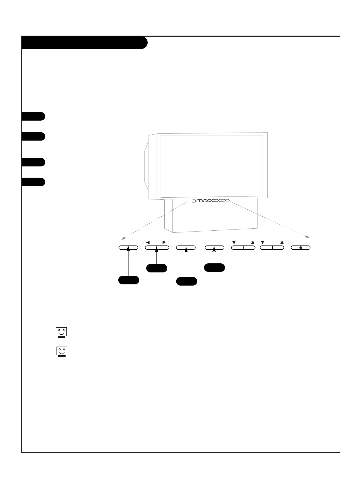
Front Panel Controls
P A GE 25
206-3533-O
enter
adjust
select
menu
power
volume
channel
To access the menus, push the
MENU button on the panel.
Use the SELECT button as the
UP/DOWN arrow buttons on your
remote.
Use the ENTER buttons as the
ENTER buttons on your remote.
Use the ADJUST LEFT/RIGHT buttons as the LEFT/RIGHT arrow
buttons on your remote.
1
2
3
4
Refer to the various pages on how
to use the on-screen menus.
The POWER, CHANNEL and VOLUME
buttons work just as they do on
your remote control.
1
2
4
3
Page 26

P A GE 26
206-3533-O
EZ Scan Setup
1
2
Use pages 8-17 to hook up your
Entertainment Machine. If you have not
done so, plug in your Entertainment
Machine into a 120V 60Hz outlet.
If you have not done so, remove the
back of the remote and put in four AAA
batteries. Make sure batteries are properly installed (check the +/– signs).
With the remote control in hand, press
the POWER button to turn on your
Entertainment Machine.
Press the MENU button so the Setup
menu appears, and then press ENTER.
Using the UP/DOWN arrow on the remote
control, select EZ Program on your
screen and then press ENTER.
Press UP/DOWN button to select EZ
Scan, then press ENTER.
Press ENTER to begin EZ Scan.
Press ENTER to stop EZ Scan.
3
4
Use EZ Scan to automatically find and store all of the stations available in your area.
5
6
7
8
back of
remote
1 2 3
4 5 6
7 8 9
0
record
pause
chapter chapter
play
stop
rewind
fast fwd
menu
enter
quit
ratio
surf
flashbk
picture
powermute
guide
vcr +
info
video dvd
clear
vcr
cable
audio
aux
tv sat
vol
ch
pg up
pg dwn
antenna dbs
4
5/6
4/5/6/7/8
3
Page 27

DTV Antenna Tune
P A GE 27
206-3533-O
Press the MENU button on the remote
control so that the Setup menu appears,
then press ENTER.
Use the UP/DOWN arrows to select DTV
Antenna Tune and then press ENTER.
Follow the directions given on screen,
adjusting your antenna if necessary.
Press ENTER to return to TV viewing.
1
2
3
1 2 3
4 5 6
7 8 9
0
record
pause
chapter chapter
play
stop
rewind
fast fwd
menu
enter
quit
ratio
surf
flashbk
picture
powermute
guide
vcr +
info
video dvd
clear
vcr
cable
audio
aux
tv sat
vol
ch
pg up
pg dwn
antenna dbs
1
2
1/2/4
4
This feature lets you know how strong your
DTV signal is and whether you need to adjust
you antenna.
Not all areas or programs are currently available in the DTV signal.
Page 28
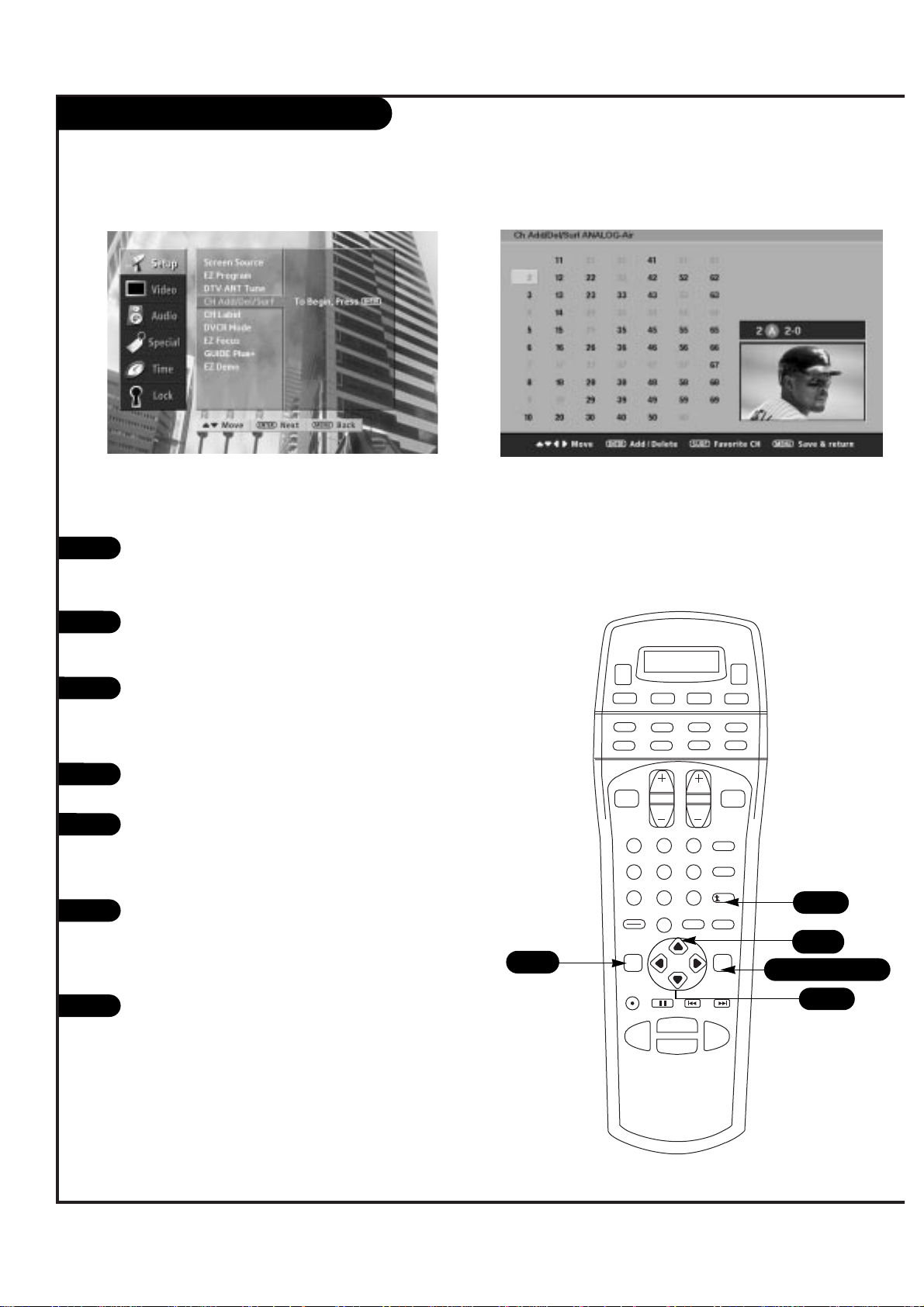
Channel Add/Delete/Surf
P A GE 28
206-3533-O
Press the MENU button on the remote
control so that the Setup menu appears,
then press ENTER.
Use the UP/DOWN arrows to select
Channel Add/Del/Surf and then press
ENTER.
Use the UP/DOWN arrows to choose from
the available modes (Analog or Digital)
to Add or Delete channels. Press ENTER
to make your selection.
Press ENTER to access the Channel
Add/Delete/Surf screen.
You will now see a screen filled with
numbers and a preview screen. Use the
UP/DOWN and LEFT/RIGHT arrows to
select any given channel.
Press ENTER to add or delete the channel
from memory. Press SURF on the remote
control to add the channel to your Surf
list (a small Surfer icon will appear in
front of the channel).
Press MENU to return to the Setup Menu.
1
2
3
4
5
1 2 3
4 5 6
7 8 9
0
record
pause
chapter chapter
play
stop
rewind
fast fwd
menu
enter
quit
ratio
surf
flashbk
picture
powermute
guide
vcr +
info
video dvd
clear
vcr
cable
audio
aux
tv sat
vol
ch
pg up
pg dwn
antenna dbs
2/3
1/2/3/4/6
6
6
7
1/7
5
Create your own channel selection for channel surfing.
Page 29

Channel Labels
P A GE 29
206-3533-O
Press the MENU button on the remote
control so that the Setup menu appears,
then press ENTER.
Use the UP/DOWN arrows to select
Channel Label and then press ENTER.
Press ENTER to access the Channel Label
screen.
You will now see a screen filled with
labels and a preview screen. Use the
UP/DOWN and LEFT/RIGHT arrows to
select the appropriate label for your
channel.
Press Channel UP/DOWN on your remote
to select the next channel to label and
press ENTER to set the label to the
selected channel.
Repeat steps four and five until all channels are labeled.
Press QUIT to save and return to TV
viewing or press MENU to save and
return to the Setup Menu.
1
2
3
4
5
1 2 3
4 5 6
7 8 9
0
record
pause
chapter chapter
play
stop
rewind
fast fwd
menu
enter
quit
ratio
surf
flashbk
picture
powermute
guide
vcr +
info
video dvd
clear
vcr
cable
audio
aux
tv sat
vol
ch
pg up
pg dwn
antenna dbs
2/3/5
2
4
5
6
7
1/7
Choose preset labels for your channels.
7
Page 30

Screen Source
P A GE 30
206-3533-O
Press the MENU button on the remote
control so that the Setup menu appears,
then press ENTER.
Use the UP/DOWN arrows to select
Screen Source.
Press ENTER to access the Screen Source
screen.
Use the UP/DOWN arrows to choose the
source for your main screen.
To select the source for the PIP screen,
first select DTV- ANT for the source of
the Main screen, then press ENTER to
access the menu for the PIP sources.
Use the UP/DOWN arrows to select the
source for the PIP screen.
Press QUIT to save and return to TV
viewing or press ENTER to save and
return to the Setup Menu.
1
2
3
4
5
1 2 3
4 5 6
7 8 9
0
record
pause
chapter chapter
play
stop
rewind
fast fwd
menu
enter
quit
ratio
surf
flashbk
picture
powermute
guide
vcr +
info
video dvd
clear
vcr
cable
audio
aux
tv sat
vol
ch
pg up
pg dwn
antenna dbs
2/4/6
1/3/5/7
6
7
1
Choose the sources for your main picture and PIP.
This menu is where you switch input source devices so you can watch your
antenna, cable TV, VCR, DVD, or anything else that you have hooked up to your
Entertainment Machine. Digital television signals will come through DTV-ANT.
Analog antenna or cable will come through either Antenna/Cable 1 or
Antenna/Cable 2, depending on how you set up your system. All other devices
will correspond to the names of the jacks that they’re connected to.
7
Page 31

DVCR Mode
P A GE 31
206-3533-O
Press the MENU button on the remote
control so that the Setup menu appears,
then press ENTER.
Use the UP/DOWN arrows to select DVCR
Mode and then press ENTER.
Use the UP/DOWN arrows to choose On
or Off for the DVCR Mode.
Press ENTER to return.
1
2
3
4
1 2 3
4 5 6
7 8 9
0
record
pause
chapter chapter
play
stop
rewind
fast fwd
menu
enter
quit
ratio
surf
flashbk
picture
powermute
guide
vcr +
info
video dvd
clear
vcr
cable
audio
aux
tv sat
vol
ch
pg up
pg dwn
antenna dbs
2/3
1/2/4
1
Page 32
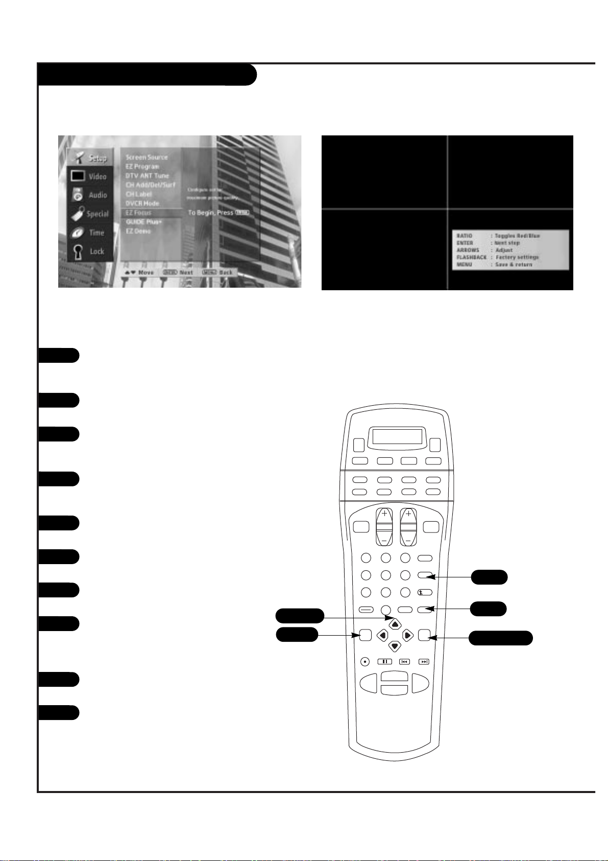
EZ Focus
P A GE 32
206-3533-O
Press the MENU button on the remote
control so that the Setup menu appears,
then press ENTER.
Use the UP/DOWN arrows to select EZ
Focus and then press ENTER.
Press the RATIO button on your remote
to toggle between Red and Blue. (Repeat
step three for each color.)
Using the UP/DOWN and LEFT/RIGHT
arrows, adjust the convergence of your
Entertainment Machine.
Press FLASHBK on the remote to return
to factory settings.
Press ENTER to save this position and
continue to the next step.
Again, press RATIO to toggle between
Red and Blue.
Press ENTER to toggle convergence mode
and the RIGHT/LEFT and UP/DOWN
arrows to adjust and move the convergence position.
Press FLASHBK on the remote to return
to factory settings.
Press MENU to save and return to the
Setup Menu.
1
2
3
4
1 2 3
4 5 6
7 8 9
0
record
pause
chapter chapter
play
stop
rewind
fast fwd
menu
enter
quit
ratio
surf
flashbk
picture
powermute
guide
vcr +
info
video dvd
clear
vcr
cable
audio
aux
tv sat
vol
ch
pg up
pg dwn
antenna dbs
2/4/8
1/2/6/8
1/10
5
6
7
8
9
10
3/7
5/9
Page 33
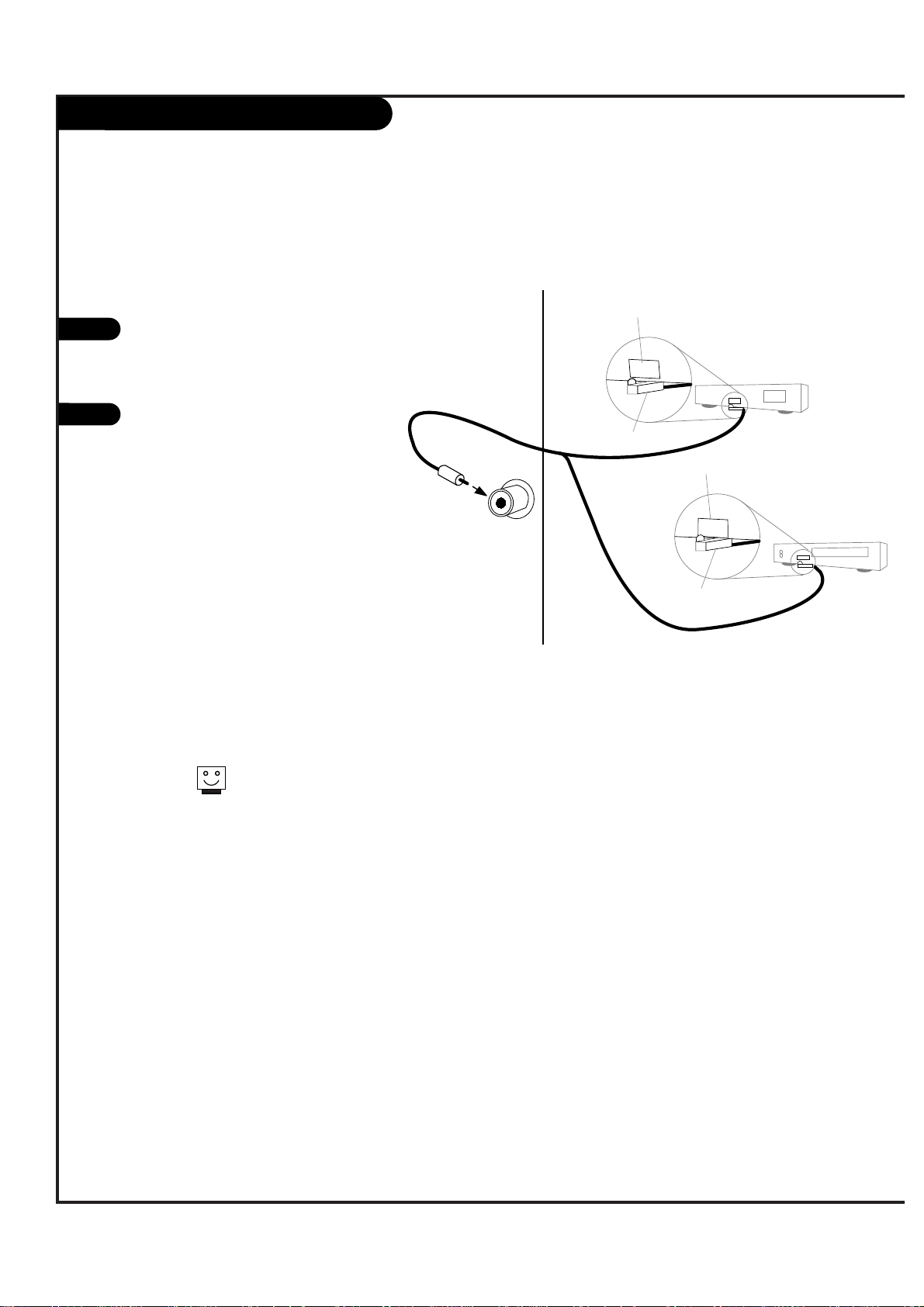
GUIDE Plus+ System Connection
P A GE 33
206-3533-O
Locate the jack marked G-Link.
This jack is for the IR
Cord connection. Insert the
connector into the G-Link.
Place the other end of the
cords with the IR (Infrared)
emitter sending units in
front of your VCR and Cable
Box in such a way as to
allow for an unrestricted
path for the IR signals to be
able to reach the front panels of the VCR and Cable Box.
If necessary, peel off the
green protective strips from
the front and back of the IR
emitter to hold emitter in
proper location.
1
2
IR emitter
IR emitter
IR receiver
IR receiver
VCR
G-LINK
Cable Box
17
In order to receive the GUIDE
Plus+ signal, it is necessary to
connect your TV through the
Antenna/Cable #1 jack on the rear
of the TV.
Page 34

206-3533-O
Mini glossary
GUIDE PLUS+ Multi-day listing of the programs scheduled to be broadcast in your area.
WATCH TV will tune to program as it is broadcast.
RECORD Program will be recorded as it is broadcast automatically.
VCR PLUS+ Recording using PlusCode programming number, usually listed with programs in Grid. Access by pressing INFO.
GUIDE Plus+ Watch/Record Menu
Point remote at TV and press the TV button.
Press GUIDE to place Grid Guide on TV screen. (Follow on-screen
instructions as instructed.)
Use the Up/Down/Left/Right arrows to pick a program on the Grid
Guide you want to watch/record.
Watch: Press Blue Action Button (VIDEO) to schedule the program to
be watched. (Blue button)
Record: Press Green Action Button (DVD) to schedule the program to
be recorded. (Green Button)
Press VCR+ button to go to the VCR Plus+ PlusCode recording menu.
Press GUIDE to return to TV viewing.
1
2
3
4
(Note: You must first set up the GUIDE Plus+ system before you
can schedule programs to be watched or recorded, see next page.)
1 2 3
4 5 6
7 8 9
0
record
pause
chapter chapter
play
stop
rewind
fast fwd
menu
enter
quit
ratio
surf
flashbk
picture
powermute
guide
vcr +
info
video dvd
clear
vcr
cable
audio
aux
tv sat
vol
ch
pg up
pg dwn
antenna dbs
1
3
2/4
Schedules programs to be Watched and/or Recorded using the
Program Grid Guide menu
3
P A GE 34
Page 35

GUIDE Plus+ Overview and Setup
Write in Setup Information
(Use a pencil.)
___________ Your Zip Code
___________ Name on your Cable Box
___________ Cable Box Output Channel
___________ Name on your VCR
Signal Reception: (Check one)
___ Over-the-Air ____ Cable Service Subscriber
Preview GUIDE Plus+ Options
Go to the Special Features menu and highlight the GUIDE Plus+
option. Press the Right arrow on the remote.
In the “What would you like to do menu”, select View Demo and
press ENTER. You will see on-screen examples of the options
available in the GUIDE Plus+ feature. Once you are familiar with
the options available, select Setup.
Run GUIDE Plus+ Setup
With the Setup option highlighted, press ENTER.
Answer the questions using the answers you wrote in the Write
in Setup Information box above.
Continue to fill-in the information on the Setup menus which
will be used to run the Cable Box and VCR tests.
Cable Box Setup and Test
This test determines if the TV can control your Cable Box.
Follow the on-screen instructions to set up your Cable Box.
VCR Setup and Test
This test determines if the TV can control your VCR.
Follow the on-screen instructions to set up your VCR.
Once the tests are complete, you can use the GUIDE Plus+ feature to view, schedule to watch, and schedule to record, the programs listed in the Program Grid Guide.
Get Information Ready for the EZ Setup
Prior to the GUIDE Plus+ feature setup, and the VCR and
Cable box tests, you will need to have handy the following
information:
- Your Zip or Postal Code.
- Whether you receive programs over-the-air, or subscribe to
a cable service.
- Name on your cable box, if you have one.
- Name on your VCR, if you have one.
- Cable Box output channel number.
(Usually located on the back of the cable box. If not there
see your cable box owner’s manual or call your cable service
provider for the number.)
Overview
GUIDE Plus+ is a feature that allows you to program your TV to:
Watch: TV will tune to the program automatically as it is aired. (If necessary, will turn TV on.)
Record: TV will tune cable box and/or VCR to the channel of the program and make the recording.
The feature also allows you to view on-screen the current program you are watching as well as to
browse the other channels to see what else is being broadcast. Advanced features allow you additional options which are available when the Program Grid Guide is on the TV screen, like VCR Plus+
recording.
Setting up your TV to receive the GUIDE Plus+ system
1
206-3533-O
P A GE 35
Page 36

GUIDE Plus+ Remote Button Functions
tune
timer
swap
move
pip +
pip -
pip
1 2 3
4 5 6
7 8 9
0
record
pause
chapter chapter
play
stop
rewind
fast fwd
menu
enter
quit
ratio
surf
flashbk
picture
powermute
guide
vcr +
info
video dvd
clear
vcr
cable
audio
aux
tv sat
vol
ch
pg up
pg dwn
antenna dbs
freez
VIDEO
Blue Button, sets pro-
gram up to be watched.
What the remote control keys do in GUIDE Plus+ operating mode with Program Grid Guide on TV screen
INFO
Displays secondary
level of program information.
Page UP
Moves to the next full
page of information on
Program Grid.
Page DOWN
Moves to the previous full
page of information on
Program Grid.
Up/Down/Left/Right
Arrows
Use to move within the
Program Grid Guide.
MENU
Provides direct access
to the Menu bar with
Grid on TV.
VCR Plus+
Enters the VCR Plus+
Recording mode. One-touch
recording of program selected
on Grid. Note: VCR Plus+
PlusCodes can be viewed by
pressing INFO with the pro-
gram you want to record
highlighted in the Program
Grid Guide.
PlusCodes are also usually
included with program listings
in your local TV guide.
Number Keypad
Enters number values
where required.
ENTER
Goes to highlighted
channel on Grid. Accepts
the action.
GUIDE Plus+
Goes to highlighted channel
on Grid. Enters and exits the
GUIDE Plus+ feature.
CLEAR
Returns to the last
channel selected before
entering the Program
Grid Guide.
DVD
Green Button, sets program up to be recorded.
PIP (Locks/Unlocks PIP)
In PIP lock, the selected TV
channel remains fixed as the
user scrolls through the list
of other available channels.
P A GE 36
206-3533-O
Page 37

GUIDE Plus+ Grid Guide Layout
Info Box
With program highlighted, shows: Title of program; Gives a short
description; Start time; Program duration; Channel number; Call
letters of the channel; Indicates by displaying icons, if captions
are present; Audio available; and Parental Control Ratings.
With the program highlighted, press the INFO button to expand
the information box and display any available additional information, and the VCR Plus+ Recording PlusCode, if available.
If still more info is available on additional screens, press INFO
again to show them.
Menu Bar
Displays services and menus (Grid options) available by first
highlighting the word GRID, then pressing the right arrow to
scroll and access the additional options: Grid, Sort, Schedule,
Messages, Editor, Setup. (See next page.)
Program Grid
Shows listing of current programs and channel icon, available
with time of day to Watch or Record. Also shows last channel
viewed. Channels are arranged in a predetermined order, which
can be edited by using the Editor option on the Menu Bar.
Explains program Grid menu features in GUIDE Plus+ mode
Current Time
Shows current time.
PIP (Picture-in-Picture)
Live video of selected program, while user is scrolling the
Program Grid. Click GUIDE to place this program on TV screen
and exit Grid Guide. Using PIP Lock/Unlock button, picture in
window can be locked, while user scrolls other programs in
Grid, or unlocked, user can see the video of the highlighted
program on the Grid (assuming the program is currently being
broadcast).
Current or Upcoming Program Ads
Displays Ads for current and upcoming programs. You can
choose to watch or record the programs shown here. Highlight
this box, then press VIDEO (Blue) to Watch, or DVD (Green) to
Record the program.
Action Bar
Watch: Automatically sets up the TV to tune to a program as it
is broadcast. Press VIDEO (Blue) = Watch.
Record: Automatically sets up the VCR to record a program as it
is broadcast. Press DVD (Green) = Record.
Current Time
Picture-in-Picture
Current or upcoming program Ads
Menu Bar
Action Bar
Current or upcoming program Ads
Program Grid
Info Box
206-3533-O
P A GE 37
Page 38

P A GE 38
206-3533-O
GUIDE Plus+ Additional Features
Record and Also Watch
Press VIDEO, DVD, or VCR+ twice to get additional recording times options and also to specify WATCH for the program you have scheduled to record.
VCR Plus+ Recording
Press VCR+ to record using the PlusCode programming number.
PIP Lock
Picture remains of original channel as other channels are
selected.
PIP Unlock
Picture is shown of channel as it is highlighted in Program
Grid Guide.
Sort Screen
Lists programs for all channels by category and sub-category for multiple days.
Record/Watch Screen
Shows date, title, and start time of the programs that are
scheduled to be watched or recorded. Also allows the user
to delete any programs, and make changes to the recording
specifics, like number of times to be recorded and recording speed.
Channel Editor (Customizes Program Guide)
Change channel order of appearance, Activate/Deactivate
Channels: Active, channels appear in Grid. Not Active,
channels do not appear in Grid guide.
Menu Bar (Additional options)
Grid
Displays program listings by channel and time.
Sort
Displays program listing by category and time, for
example, Sports, Movies, etc.
Schedule
Shows a list of programs set to be watched or
recorded. Edit the schedule to remove programs
or change recording options.
Messages
Displays a list of messages sent to the Guide.
Editor
Displays your channel lineup; each channel may
be turned on or off. (Will appear, won’t appear.)
Setup
Use to change Guide Setup, Zip or Postal Code,
Cable Box and VCR settings and also to view the
GUIDE Plus+ Overview Demo.
Customize and edit your GUIDE Plus+ Grid menu and setup - - Troubleshoot problems
TROUBLESHOOTING
Won’t record or watch.
- Setup was not performed.
Only Records in SP (Short Play)
- Press VIDEO, DVD or VCR+ twice to get recording options
menu.
Doesn’t display programs in Grid
- TV not turned off long enough for data to be received.
- Cables not connected?
Page 39

P A GE 39
206-3533-O
Video Menu
Press the MENU button on the remote
control so that the Setup menu appears,
then press the DOWN arrow button to
select the Video Menu. Or just press the
PICTURE button skip to instantly access
the Video Menu.
Press ENTER to access the Video Menu.
Use the UP/DOWN arrows to select one
of the following options. Your options
are:
• Contrast: Changes the amount of differ-
ence between black levels and white levels
in your picture.
• Brightness: Increases or decreases the
amount of white in your picture.
• Sharpness: Raise or lower the definition
of the picture. The lower the level, the
softer the image will appear.
• Color: Adjust levels of all colors.
• Tint: Adjust the relative amounts of the
color red and green in your picture.
• Color Temperature: Set this to Warm for
hotter colors such as red, or set to cool for
less intense colors with more blue.
• EZ Video: Choose from a range of options
depending on your viewing situation.
Custom: Uses the settings you have manually chosen.
Normal: Restores the levels to their original
settings.
Movie Adjusts Video settings to enhance
Movie viewing.
Video Game: Adjusts Video settings to
enhance video games.
Sports: Adjusts Video settings to enhance
sporting events.
Weak Signal: Adjusts Video settings to compensate for a weak reception.
Daylight: Adjusts Video settings for daylight
conditions.
Use the LEFT/RIGHT arrows to adjust your preferences.
Press the ENTER button to save your choices
and return to TV viewing.
1
2
3
4
1 2 3
4 5 6
7 8 9
0
record
pause
chapter chapter
play
stop
rewind
fast fwd
menu
enter
quit
ratio
surf
flashbk
picture
powermute
guide
vcr +
info
video dvd
clear
vcr
cable
audio
aux
tv sat
vol
ch
pg up
pg dwn
antenna dbs
3/4
2/5
1
5
Customize the picture quality on your Entertainment
Machine.
1
Page 40

Audio Menu
Press the MENU button on the remote
control so that the Setup menu appears,
then press the DOWN arrow button to
select the Audio Menu.
Press ENTER to access the Audio Menu.
Use the UP/DOWN arrows to select one
of the following options. Your options
are:
• Bass: Increase or decrease lower-end
sounds.
• Treble: Increase or decrease higher-end
sounds.
• EZ Sound: Allows you to choose an appro-
priate listening setting based on different
audio options. They are: Custom, Normal,
Stadium, News, Music and Theater. Normal
resets all audio settings to the original levels.
• EZ SoundRite: Scans for changes in sound
level during commercials, then adjusts the
sound to match your current audio levels.
This will make sure that the volume level
will be consistent whether you are watching
commercials or a regular TV program.
• Audio Mode: If you want to change the
sound from Mono, SAP or Stereo in Analog
channel or the language from English,
French, or Spanish in digital channel,
select this mode.
• Front Surround: Gives a sense that the
sound is open and expanded.
• Internal Speaker: Allows you to turn the
regular speakers on (STEREO) or off. Many
people who use a home stereo system with
their TV use this feature. Also you can use
TV speaker of external Multi channel audio
sounds (CENTER).
Use the LEFT/RIGHT arrows to adjust your preferences and use UP/DOWN select your preference and.
Press the ENTER button to save your choices
and return to TV viewing.
1
2
3
4
1 2 3
4 5 6
7 8 9
0
record
pause
chapter chapter
play
stop
rewind
fast fwd
menu
enter
quit
ratio
surf
flashbk
picture
powermute
guide
vcr +
info
video dvd
clear
vcr
cable
audio
aux
tv sat
vol
ch
pg up
pg dwn
antenna dbs
3/4
2/5
1
5
Customize the sound on your Entertainment
Machine.
206-3533-O
P A GE 40
Page 41

P A GE 41
206-3533-O
Aspect Ratio
Press the MENU button on the remote
control so that the Setup menu appears,
then press the DOWN arrow button
repeatedly to select the Special Menu. Or
press RATIO button to instantly access
the Aspect Ratio Menu.
Press ENTER to activate the Special
Menu.
Use the UP/DOWN arrows to choose
Aspect Ratio.
Press ENTER to move into the Aspect
Ratio selection menu. Use the UP/DOWN
arrow buttons to select the right ratio
for your viewing environment:
• 4:3 - A general TV format.
• 16:9 - A cinema screen picture format.
• ZOOM - A format with magnified
upper/lower sides. The bottom and
top of the picture may be lost.
Press QUIT to save and return to TV
viewing or press ENTER to save and
return to the Special Menu.
1
2
3
4
1 2 3
4 5 6
7 8 9
0
record
pause
chapter chapter
play
stop
rewind
fast fwd
menu
enter
quit
ratio
surf
flashbk
picture
powermute
guide
vcr +
info
video dvd
clear
vcr
cable
audio
aux
tv sat
vol
ch
pg up
pg dwn
antenna dbs
1/3/4
2/4/5
1
5
Select the screen size for the program you are viewing.
5
1
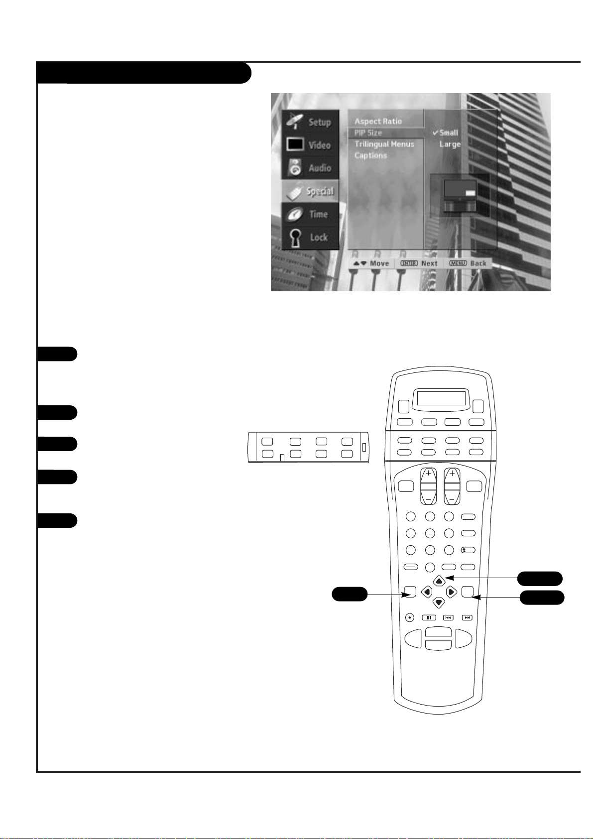
Page 42
P A GE 42
206-3533-O
Press the MENU button on the remote
control so that the Setup menu appears,
then press the DOWN arrow button
repeatedly to select the Special Menu.
Press ENTER to activate the Special
Menu.
Use the UP/DOWN arrows to choose PIP
Size.
Press ENTER to move into the PIP size
selection menu. Use the UP/DOWN arrow
buttons to select Small or Large.
Press ENTER to save and return to TV
viewing.
1
2
3
4
tune
timer
swap
move
pip +
pip -
pip
1 2 3
4 5 6
7 8 9
0
record
pause
chapter chapter
play
stop
rewind
fast fwd
menu
enter
quit
ratio
surf
flashbk
picture
powermute
guide
vcr +
info
video dvd
clear
vcr
cable
audio
aux
tv sat
vol
ch
pg up
pg dwn
antenna dbs
freez
1/3/4
2/4/5
1
5
Adjust the size of your Picture-in-Picture window.
PIP Size
Page 43

P A GE 43
206-3533-O
On-Screen Languages
Press the MENU button on the remote
control so that the Setup menu appears,
then press the DOWN arrow button
repeatedly to select the Special Menu.
Press ENTER to activate the Special
Menu.
Use the UP/DOWN arrows to choose
Trilingual Menus.
Press ENTER to move into the Language
selection menu. Use the UP/DOWN arrow
buttons to select the language you wish
to view your on-screen menus.
Press QUIT to save and return to TV
viewing or press ENTER to save and
return to the Special Menu.
1
2
3
4
1 2 3
4 5 6
7 8 9
0
record
pause
chapter chapter
play
stop
rewind
fast fwd
menu
enter
quit
ratio
surf
flashbk
picture
powermute
guide
vcr +
info
video dvd
clear
vcr
cable
audio
aux
tv sat
vol
ch
pg up
pg dwn
antenna dbs
1/3/4
2/4/5
1
5
Choose the languages for your on-screen menus.
5
Page 44

P A GE 44
206-3533-O
Press the MENU button on the remote
control so that the Setup menu appears,
then press the DOWN arrow button
repeatedly to select the Special Menu.
Press ENTER to activate the Special
Menu.
Use the UP/DOWN arrows to choose
Captions, then press ENTER.
Press ENTER to move into the Captions
selection menu. Use the UP/DOWN arrow
buttons to make your caption selection.
Your choices are: Off, Caption 1, Caption
2, Caption 3, Caption 4, Text 1, Text 2,
Text 3 and Text 4.
Press QUIT to save and return to TV
viewing or press ENTER to save and
return to the Special Menu.
1
2
3
4
1 2 3
4 5 6
7 8 9
0
record
pause
chapter chapter
play
stop
rewind
fast fwd
menu
enter
quit
ratio
surf
flashbk
picture
powermute
guide
vcr +
info
video dvd
clear
vcr
cable
audio
aux
tv sat
vol
ch
pg up
pg dwn
antenna dbs
1/3/4
2/3/4/5
1
5
Turn closed captioning or text on, or off.
5
Captions/Text
Page 45

P A GE 45
206-3533-O
EZ Demo
Press the MENU button on the remote
control so that the Setup menu appears.
Press ENTER to activate the Setup Menu.
Use the UP/DOWN arrows to choose EZ
Demo, then press ENTER to activate EZ
Demo.
Press any button on the remote to stop
EZ Demo.
1
2
3
4
1 2 3
4 5 6
7 8 9
0
record
pause
chapter chapter
play
stop
rewind
fast fwd
menu
enter
quit
ratio
surf
flashbk
picture
powermute
guide
vcr +
info
video dvd
clear
vcr
cable
audio
aux
tv sat
vol
ch
pg up
pg dwn
antenna dbs
3
2/31
Your Entertainment Machine will show you all your
menu options.
EZ Demo can be activated when
“Screen Source” is in “DTV-ANT,”
“ANT/CABLE 1” or “ANT/CABLE 2.”
Page 46
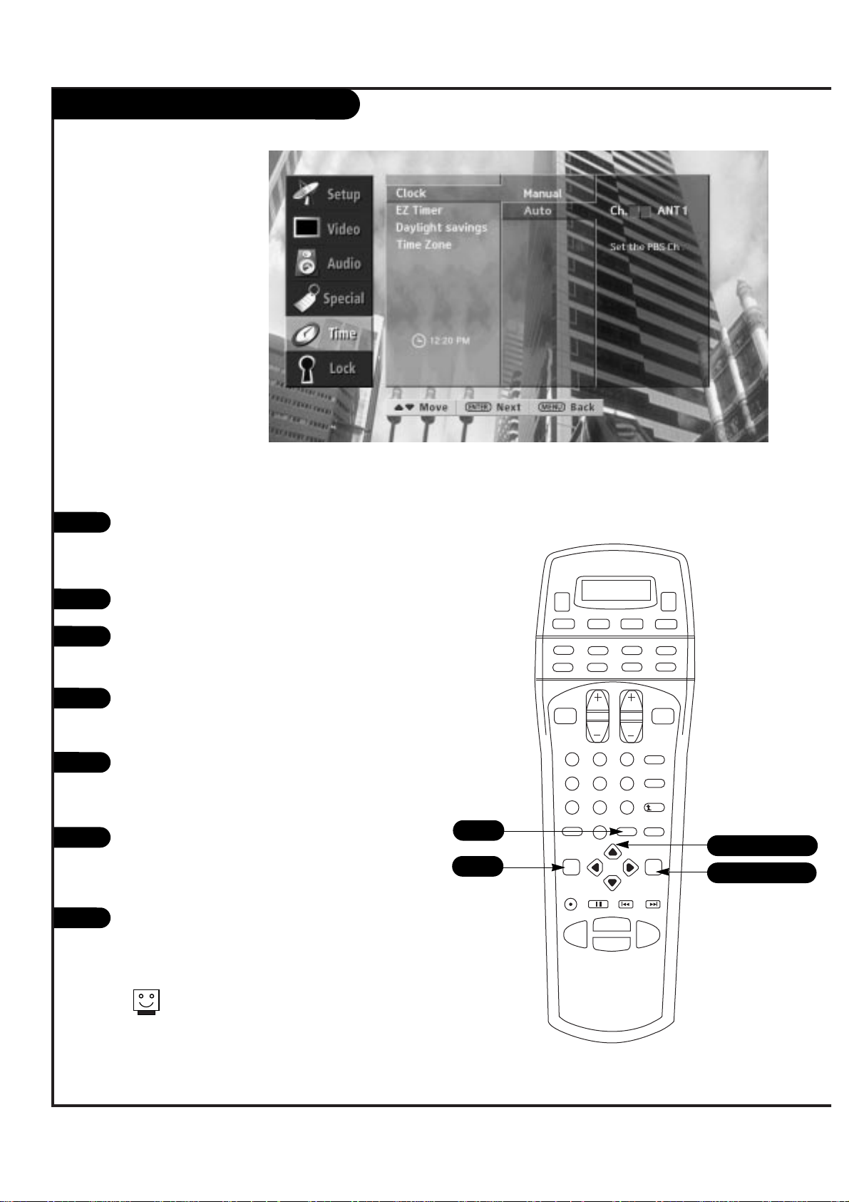
P A GE 46
206-3533-O
Clock Set
Press the MENU button on the remote
control so that the Setup menu appears,
then press the DOWN arrow button
repeatedly to select the Time Menu.
Press ENTER to activate the Time Menu.
Use the UP/DOWN arrows to choose
Clock, then press ENTER to activate Clock
Set.
Use the UP/DOWN arrows to select
Manual or Auto press ENTER to make
your selection.
If you choose Manual, use the UP/DOWN
arrows and ENTER/MENU buttons to set
the date and time on your Entertainment
Machine.
If you choose Auto, you will be prompted to enter the local PBS channel. Use
the UP/DOWN arrows to set the PBS
channel.
Press ENTER to return to TV viewing and
activate correct time, or press QUIT to
save and return to TV viewing.
1
2
3
4
1 2 3
4 5 6
7 8 9
0
record
pause
chapter chapter
play
stop
rewind
fast fwd
menu
enter
quit
ratio
surf
flashbk
picture
powermute
guide
vcr +
info
video dvd
clear
vcr
cable
audio
aux
tv sat
vol
ch
pg up
pg dwn
antenna dbs
1/3/4/5/6
2/3/4/5/7
1/5
5
6
7
7
Set the clock or have it done
for you, automatically.
Daylight Savings and Time Zone
can be activated when clock is
Auto.
Page 47
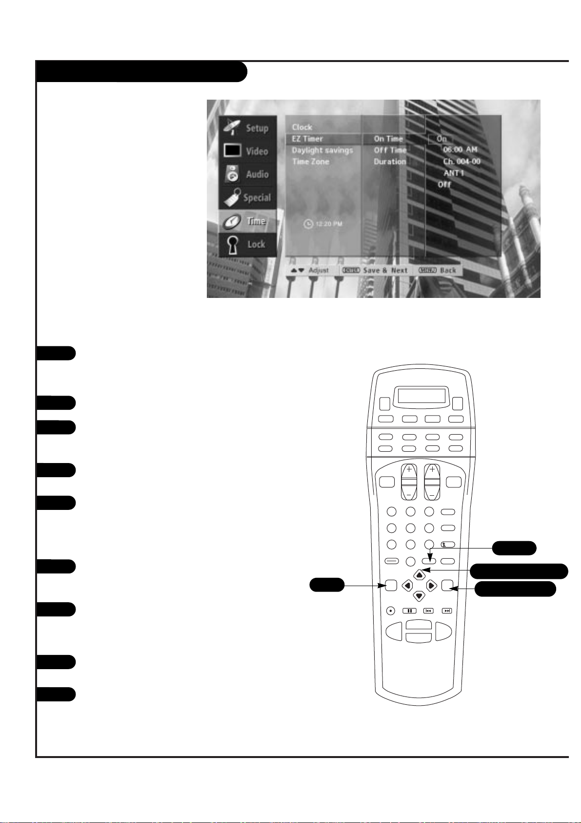
P A GE 47
206-3533-O
EZ Timer
Press the MENU button on the remote
control so that the Setup menu appears,
then press the DOWN arrow button
repeatedly to select the Time Menu.
Press ENTER to activate the Time Menu.
Use the UP/DOWN arrows to select EZ
Timer, then press ENTER to activate EZ
Timer.
Use the UP/DOWN arrows to select the
On Time.
Press ENTER again to begin setting the
On Timer. Use the UP/DOWN arrow buttons and the ENTER/MENU buttons to set
the On Time. Use the UP/DOWN arrows
to set the Channel.
Use the UP/DOWN arrows to select the
Off Time repeat and step five to set the
Off Time.
Instead of setting the Off Time, you
could simply select Duration. Use the
UP/DOWN arrow buttons to select
Duration and then press ENTER.
Select from the listed time lengths using
the UP/DOWN arrow buttons.
Press ENTER to save and return to the
Time Menu, or press QUIT to save and
return to TV viewing.
1
2
3
4
1 2 3
4 5 6
7 8 9
0
record
pause
chapter chapter
play
stop
rewind
fast fwd
menu
enter
quit
ratio
surf
flashbk
picture
powermute
guide
vcr +
info
video dvd
clear
vcr
cable
audio
aux
tv sat
vol
ch
pg up
pg dwn
antenna dbs
1/3/4/5/6/7/8
2/3/5/7/9
1
5
6
7
8
9
Have your Entertainment Machine
wake up and go to sleep anytime.
9
Page 48

P A GE 48
206-3533-O
Daylight Savings
Press the MENU button on the remote
control so that the Setup menu appears,
then press the DOWN arrow button
repeatedly to select the Time Menu.
Press ENTER to activate the Time Menu.
Use the UP/DOWN arrows to choose
Daylight savings then press ENTER to
activate Daylight savings.
Use the UP/DOWN arrows to choose On
or Off.
Press ENTER to save and return to the
Time Menu, or press QUIT to save and
return to TV viewing.
1
2
3
4
1 2 3
4 5 6
7 8 9
0
record
pause
chapter chapter
play
stop
rewind
fast fwd
menu
enter
quit
ratio
surf
flashbk
picture
powermute
guide
vcr +
info
video dvd
clear
vcr
cable
audio
aux
tv sat
vol
ch
pg up
pg dwn
antenna dbs
1/3/4
2/3/5
1
5
5
Set your entertainment Machine for Daylight
Savings
Page 49

P A GE 49
206-3533-O
Press the MENU button on the remote
control so that the Setup menu appears,
then press the DOWN arrow button
repeatedly to select the Time Menu.
Press ENTER to activate the Time Menu.
Use the UP/DOWN arrows to choose Time
Zone then press ENTER to activate Time
Zone.
Use the UP/DOWN arrows to choose your
Time Zone.
Press ENTER to save and return to the
Time Menu, or press QUIT to save and
return to TV viewing.
1
2
3
4
1 2 3
4 5 6
7 8 9
0
record
pause
chapter chapter
play
stop
rewind
fast fwd
menu
enter
quit
ratio
surf
flashbk
picture
powermute
guide
vcr +
info
video dvd
clear
vcr
cable
audio
aux
tv sat
vol
ch
pg up
pg dwn
antenna dbs
1/3/4
2/3/5
1
5
5
Choose the Time Zone for the clock on your Entertainment
Machine.
Time Zone
Page 50

P A GE 50
206-3533-O
Parental Lock
Press the MENU button on the remote
control so that the Setup menu appears,
then press the DOWN arrow button
repeatedly to select the Lock Menu.
Press ENTER to activate the Lock Menu.
Enter your password using the number
keypad. (Select “Set Password” to
change the password.)
Press ENTER to select Lock On/Off.
Press the UP/DOWN arrow buttons to
control parental lock. (The values set in
Parental control are valid only when they
are appointed as Block On.
Now press the UP/DOWN arrow button to
select Set Password. Enter the new password using the number keypad. You will
be prompted to re-confirm the password.
Re-enter the password.
Next, use the UP/DOWN arrows to select
Block Channel. Press ENTER, then use
the UP/DOWN arrows to select Analog or
Digital.
For either case, you will be presented
with a splash screen of all the channels
found in the system. Use the UP/DOWN
and LEFT/RIGHT arrows to select a channel. Press the ENTER button to place a
block on the channel.
See the next page for more details on
your blocking options.
1
2
3
4
1 2 3
4 5 6
7 8 9
0
record
pause
chapter chapter
play
stop
rewind
fast fwd
menu
enter
quit
ratio
surf
flashbk
picture
powermute
guide
vcr +
info
video dvd
clear
vcr
cable
audio
aux
tv sat
vol
ch
pg up
pg dwn
antenna dbs
1/5/6/7/8
2/4/7/8
1
3
5
6
7
8
9
Determine the channels and video
your children can access.
Page 51

Parental Lock (con’t)
Press the MENU button on the remote
control to return to the Lock Menu.
Press an UP/DOWN arrow to select MPAA
(Rated), then press ENTER.
Press the UP/DOWN arrow buttons to
select one of the MPAA blocking options.
Press ENTER to save your choice.
Press the UP/DOWN arrow buttons to
select MPAA (Not Rated), then press
ENTER.
Press the UP/DOWN arrow buttons to
select either Blocked or Unblocked. Press
ENTER to save your choice.
Press the UP/DOWN arrow buttons to
select TV-PG (Aged). Press ENTER to continue.
Press the UP/DOWN arrow buttons to
select General or Children then press
ENTER.
Press the UP/DOWN arrow buttons to
select an option. Press ENTER to save
your choice.
Press the UP/DOWN arrow buttons to
select TV-PG (Content). Press ENTER to
continue.
Press the UP/DOWN arrow buttons to
select Violence, Sex, Language, Dialogue,
F. Violence, then press ENTER.
For each content, press the UP/DOWN
arrow buttons to select the rating, then
press ENTER.
Select Block Source to block Video, DVD,
or VGA inputs. Press ENTER to activate
Block Source and then use the UP/DOWN
arrows to set you options. Press ENTER
to save your choices. Repeat this step
for all sources.
10
11
12
13
1 2 3
4 5 6
7 8 9
0
record
pause
chapter chapter
play
stop
rewind
fast fwd
menu
enter
quit
ratio
surf
flashbk
picture
powermute
guide
vcr +
info
video dvd
clear
vcr
cable
audio
aux
tv sat
vol
ch
pg up
pg dwn
antenna dbs
11/12/13/14/15
16/17/18/19/20/21
11/12/13/14/15
16/17/18/19/20/21
10
14
15
16
19
17
18
20
21
Determine the channels and video your children
can access.
P A GE 51
206-3533-O
Page 52

P A GE 52
206-3533-O
Programming the Remote
Turn on the device (TV, VCR, Cable Box,
Satellite Receiver, etc.) you wish to
operate.
On the remote control, press the corresponding DEVICE button (TV, VCR, CATV
SAT, etc) and MUTE button simultaneously. Note: “SET” will appear in the LCD.
Point the remote control toward the
device. Using the NUMBER KEYPAD, enter
in the first three digit code number
assigned to your brand code list located
on pp 57-61. The device will turn off
when the correct code has been selected.
Once the device turns off, press the corresponding DEVICE button again to store
the code.
Note: LCD will flash “PASS” indicating
that the code has been stored.
Test the remote control functions with
the code that was just stored. If any of
the buttons do not perform as they
should, please repeat from Step 2 using
the next three digit code number for
your brand of equipment.
1
1 2 3
4 5 6
7 8 9
0
record
pause
chapter chapter
play
stop
rewind
fast fwd
menu
enter
quit
ratio
surf
flashbk
picture
powermute
guide
vcr +
info
video dvd
clear
vcr
cable
audio
aux
tv sat
vol
ch
pg up
pg dwn
antenna dbs
2/4
2
2
3
4
5
3
Operate all of your home theater and stereo
hardware with your Multi-Brand remote.
Page 53

P A GE 53
206-3533-O
Auto-Search
Turn on the device you wish to operate.
On the remote control, press the matching DEVICE and MUTE buttons simultaneously. Note: “SET” will appear in the
LCD.
Press the Channel UP or Channel DOWN
buttons either one step at a time or
keep it pressed. The remote control will
send out a series of codes. Release the
channel button as soon as the device
turns off. Note: the LCD will show the
code number it just sent out.
Press the device button to store the
code. Note: “PASS” will flash in the LCD
indicating that the code has been
stored.
Test the remote control functions with
the code that was just stored. If any of
the buttons do not preform as they
should, please repeat from Step 2.
1
1 2 3
4 5 6
7 8 9
0
record
pause
chapter chapter
play
stop
rewind
fast fwd
menu
enter
quit
ratio
surf
flashbk
picture
powermute
guide
vcr +
info
video dvd
clear
vcr
cable
audio
aux
tv sat
vol
ch
pg up
pg dwn
antenna dbs
2/4
2
2
3
4
5
3
Use the Remote control to search for all possible programming codes.
Page 54

P A GE 54
206-3533-O
Auto-Find
On the remote control, press the device
and mute buttons simultaneously. Note:
“SET” will appear in the LCD.
Press the PICTURE button. The LCD will
flash the three digit code number for
five seconds before returning to its original state.
1
1 2 3
4 5 6
7 8 9
0
record
pause
chapter chapter
play
stop
rewind
fast fwd
menu
enter
quit
ratio
surf
flashbk
picture
powermute
guide
vcr +
info
video dvd
clear
vcr
cable
audio
aux
tv sat
vol
ch
pg up
pg dwn
antenna dbs
1
2
2
If you wish to find a code number that has been stored in your remote control, please use the
following steps:
Page 55

P A GE 55
206-3533-O
Multi-Commands Memory Buttons
Press the DEVICE button and MUTE button, simultaneously. Note:
“SET” will appear in the LCD.
Press one of the memory buttons that you would like to designate
for multi-command or favorite channel operation. Note “M____ (1—
4)” will appear in the LCD. The memory button is now ready to be
set up.
Press up to six commands that you would like to store in the memory button. Note: Each successive selection will appear as 1-6 in the
LCD.
Press the Channel UP button to store your selection. Note:
SAVE will flash twice and the device mode will appear in the LCD.
Please repeat the above steps for the remaining memory buttons.
Memory button ANTENNA in the SAT mode can be set up to do the
following functions: to turn on the Satellite receiver, select channel
#18 on the satellite receiver, and then turn on the TV.
Press the SAT and MUTE buttons, simultaneously. Note: “SET” Will
appear in the LCD.
Press memory button ANTENNA. Note: “M____1” will appear in the
LCD.
Press the POWER button (on the remote) to turn on the Satellite
receiver. Note: “M____1 1” will appear in the LCD.
Press the #1 button to select the first digit of channel #18. Note:
“M____1 2” will appear in the LCD.
Press the #8 button to select the second digit of channel #18. Note:
“M____1 3” will appear in the LCD.
Press the TV DEVICE button to select the TV DEVICE mode. Note:
“M____1 4” will appear in the LCD.
Press the POWER button (on the remote) to turn on the TV. Note:
“M____1 5” will appear in the LCD.
Press the Channel UP button to store the above commands. Note:
“SAVE” will flash and the current Device mode will appear.
Now, anytime the memory button ANTENNA is pressed while the
remote control is in the SAT mode, the commands to turn on the
Satellite receiver, select the Satellite channel #18 and turn on the
TV, will be sent out by the remote control.
Note: Any previously stored multi-commands on a memory button
will be erased when new multi-commands are stored to that same
memory button.
1
1 2 3
4 5 6
7 8 9
0
record
pause
chapter chapter
play
stop
rewind
fast fwd
menu
enter
quit
ratio
surf
flashbk
picture
powermute
guide
vcr +
info
video dvd
clear
vcr
cable
audio
aux
tv sat
vol
ch
pg up
pg dwn
antenna dbs
1
2
3
4
5
4
Memory buttons (antenna, video, DVD and DBS) can be set up to store up to six commands with one button push. Any functions, in any
device mode (except Channel up and Channel down), can be stored in any one of the four memory buttons. This will enable you, for example,
to turn on the TV and Satellite receiver and select a preassigned satellite channel with only a one button push.
2
Example
1
2
3
4
Page 56

P A GE 56
206-3533-O
More Mode Functions
Turn on the device you wish to operate.
On the remote control, press the device
button you wish to assign this device to,
and the Mute button simultaneously.
Note: “SET will appear in the LCD.
Press the device button that corresponds
to the actual device you plan to operate.
Note: “SET” will appear in the LCD.
Select the three digit code number from
the code list found on pp 57-61 for the
device you will be operating.
Point the remote toward the device, and
press in the three digit code number.
Note: “SET ###” will appear in the LCD.
The device will turn off when the correct
three digit code number has been selected. Press the DEVICE button selected in
step 2. This will store the three digit
code into that DEVICE button. Note:
“PASS” will flash in the LCD.
1
1 2 3
4 5 6
7 8 9
0
record
pause
chapter chapter
play
stop
rewind
fast fwd
menu
enter
quit
ratio
surf
flashbk
picture
powermute
guide
vcr +
info
video dvd
clear
vcr
cable
audio
aux
tv sat
vol
ch
pg up
pg dwn
antenna dbs
2
2
3
4
5
4/5
3
The feature can be used to program the remote control for more than one TV, VCR, Satellite Receiver, etc. The
three digit code for any device can be stored in any of the DEVICE buttons. For example: For two VCRs, the first
VCR can be stored in the VCR DEVICE button under normal set up procedures, and the second VCR can be programmed into the unused CATV or any other DEVICE button.
6
Page 57

P A GE 57
206-3533-O
TV and VCR “Punch Through” Controls
Press the DEVICE button EXCEPT TV(VCR,
CATV, SAT, etc) and MUTE button simultaneously. Note: SET will appear in the
LCD.
Press the Volume (+) button. Note: “TV0” will appear in the LCD.
To deactivate the TV override, just repeat
steps 1 and 2. “TV-X” will appear in the
LCD instead of “TV-O.”
1
1 2 3
4 5 6
7 8 9
0
record
pause
chapter chapter
play
stop
rewind
fast fwd
menu
enter
quit
ratio
surf
flashbk
picture
powermute
guide
vcr +
info
video dvd
clear
vcr
cable
audio
aux
tv sat
vol
ch
pg up
pg dwn
antenna dbs
1
2
2
After setting up the remote to work with your respective TV, VCR, CATV, Satellite equipment, etc. the
remote control can also be set up so that the TV volume and VCR controls will supersede respective
equipment volume control, even when the remote control is in a different Device mode.
Press the DEVICE button EXCEPT VCR (TV,
CATV, SAT, etc) and MUTE button simultaneously. Note: SET will appear in the LCD.
Press the Volume (+) button. Note: VCR-0
will appear in the LCD.
To deactivate the VCR override, just repeat
steps 1 and 2. “VCR-X” will appear in the
LCD instead of “VCR-O.”
1
2
TV Volume
VCR Controls
3
3
Page 58

P A GE 58
206-3533-O
Programming Codes
Akai . . . . . . . . . . 146
Amark . . . . . . . . 112 143
Ampro. . . . . . . . . 167 073
Blaupunkt . . . . . . 088
Candle . . . . . . . . 002 003 004
Capehart . . . . . . . 058
Citizen . . . . . . . . 002 003 004
043 101 103
143
Classic . . . . . . . . 043
Concerto . . . . . . . 004
Contec . . . . . . . . 039 043 050
051
Coronado. . . . . . . 143
Craig. . . . . . . . . . 043 054
Crown . . . . . . . . . 043 143
Curtis Mathes . . . . 101 1161143
Daewoo . . . . . . . 004 016 017
043 044 055
071 076 103
107 111 114
117 120 123
125 127 128
136 143
Daytron . . . . . . . 116 143
Dynasty. . . . . . . . 043
Dynatech. . . . . . . 062
Electrohome. . . . . 007 143
Emerson . . . . . . . 028 048 043
155 005 096
047 116 153
154 051 143
151 001 050
Fisher . . . . . . . . . 077 057
Funai . . . . . . . . . 028 043
Futuretech . . . . . . 043
General Electric . . 160 144 165
073 130 001
008 009 034
056 074 116
155 091
Goldstar . . . . . . . 102 106 110
112 113 116
119 122 127
137 143
Hall Mark. . . . . . . 116
Hitachi . . . . . . . . 011 163 166
158 143 004
010 012 023
075 001 009
041
Infinity . . . . . . . . 164
Inkel . . . . . . . . . 129
JBL . . . . . . . . . . 164
J.C. Penney . . . . . 008 030 065
101 160 004
024 143 009
156
Jensen . . . . . . . . 013
JVC . . . . . . . . . . 038 083 145
034
KEC . . . . . . . . . . 043
Kloss . . . . . . . . . 002 059
KMC . . . . . . . . . . 143
KTV . . . . . . . . . . 043 001 143
154
Lodgenet. . . . . . . 072
Logik . . . . . . . . . 072
Luxman . . . . . . . . 004
LXI . . . . . . . . . . 166 007 015
164 160 081
052
Magnavox . . . . . . 164 059 001
003 060 061
063 064 160
004 143 127
Marantz . . . . . . . 001 164 077
Matsui . . . . . . . . 164
Memorex . . . . . . . 007 072 116
Metz. . . . . . . . . . 088
MGA . . . . . . . . . . 004 028 042
049 077 116
Minerva. . . . . . . . 088
Mitsubishi . . . . . . 109 024 124
001 004 040
116 146 028
042
MTC . . . . . . . . . 101 004 062
NAD . . . . . . . . . . 015 025
NEC . . . . . . . . . . 132 130 134
001 040 016
024 056 007
019
Nikei . . . . . . . . . 043
Onking . . . . . . . . 043
Onwa . . . . . . . . . 043
Optonica . . . . . . . 019 081
Panasonic . . . . . . 034 080 092
056 164
Philco. . . . . . . . . 003 024 056
059 060 063
064 164 004
143 043 127
Philips . . . . . . . . 164 038 070
093 001 003
004 143 059
160
Pioneer . . . . . . . . 135 025 023
001 018 116
027
Portland . . . . . . . 004 143
ProScan . . . . . . . 144
Proton . . . . . . . . 116 131 143
058 171
Quasar . . . . . . . . 034 092 056
Radio Shack . . . . . 019 043 047
116 127 143
RCA . . . . . . . . . . 160 161 165
065 156 144
001 004 023
024 056 074
152
Realistic . . . . . . . 007 019 043
047
Runco . . . . . . . . . 168 169
Sampo . . . . . . . . 058 116
Samsung . . . . . . . 050 089 101
105 113 116
127 133 137
143 160
Sanyo . . . . . . . . . 166 007 057
082 020 053
021 033 039
Scott . . . . . . . . . 028 043 116
143 048
Sears . . . . . . . . . 015 030 004
007 028 057
143 094 160
116 082 101
Sharp . . . . . . . . . 170 081 019
028 029 014
004 022 143
Siemens. . . . . . . . 088
Signature. . . . . . . 072
Sony . . . . . . . . . 070 147 126
085 139 041
079
Soundesign . . . . . 028 003 043
116
Spectricon . . . . . . 112
SSS . . . . . . . . . . 004 043 116
Supre Macy . . . . . 002
Sylvania . . . . . . . 003 059 060
063 064 164
044 160 116
127 140
Tandy . . . . . . . . . 081
Tatung . . . . . . . . 056 062
Technics . . . . . . . 084
Techwood . . . . . . 004
Teknika . . . . . . . . 002 003 004
024 028 043
072 101 143
031 077 103
Telefunken. . . . . . 037 046 086
087
Telerent . . . . . . . 072
TMK . . . . . . . . . . 004 116
Toshiba . . . . . . . 015 138 030
007 040 062
101 051
Totevision . . . . . . 143
Universal. . . . . . . 008 009
Video Concepts . . . 146
Vidtech . . . . . . . . 004 116
Wards . . . . . . . . . 004 008 009
019 028 060
061 063 064
072 074 116
143
Yamaha. . . . . . . . 004
York . . . . . . . . . . 116
Yupiteru . . . . . . . 043
Zenith . . . . . . . . 072 073 095
157
Zonda . . . . . . . . . 112
TVs
Page 59

P A GE 59
206-3533-O
Programming Codes
Aiwa . . . . . . . . . 034
Akai . . . . . . . . . . 146 043 046
124 125 142
016
Ampro. . . . . . . . . 072
Audio Dynamics . . 012 023 039
043
Broksonic . . . . . . 035 037 129
Canon . . . . . . . . 028 031 033
Capehart . . . . . . . 108
Craig . . . . . . . . . 003 040 135
Curtis Mathes . . . 031 033 041
Daewoo . . . . . . . 005 007 010
064 065 108
110 111 112
116 117 119
Daytron . . . . . . . 108
DBX . . . . . . . . . . 012 023 039
043
Dynatech. . . . . . . 034 053
Electrohome. . . . . 059
Emerson . . . . . . . 006 029 035
025 027 034
036 037 046
101 129 131
138 017 031
Fisher . . . . . . . . . 003 008 009
010
Funai . . . . . . . . . 034
General Electric . . 031 072 144
147 033 063
107 109
Goldstar . . . . . . . 012 013 020
101 106 114
123
Go Video . . . . . . . 132 136
Harman Kardon. . . 012 045
Hitachi . . . . . . . . 004 026 034
043 150 063
137 018
Instant Replay . . . 031 033
JCL. . . . . . . . . . . 031 033
J.C. Penny . . . . . . 012 013 015
066 040 033
101
Jensen . . . . . . . . 043
JVC . . . . . . . . . . 048 043 130
150 050 055
060 012 031
033
Kenwood . . . . . . . 014 043 048
039
Lloyd . . . . . . . . . 034
LXI . . . . . . . . . . 034 101 013
014
Magin . . . . . . . . . 040
Magnavox . . . . . . 067 031 034
041 033 068
Marantz . . . . . . . 031 067 012
033 069
Marta . . . . . . . . . 101
Matsui . . . . . . . . 027 030
MEI . . . . . . . . . . 031 033
Memorex . . . . . . . 101 003 010
014 031 034
053 072 139
134 033
MGA . . . . . . . . . . 045 046 059
Minolta . . . . . . . . 013 020
Mitsubishi . . . . . . 059 061 151
142 013 020
045 049
MTC . . . . . . . . . . 034 040
Multi Tech . . . . . . 024 034
NEC . . . . . . . . . . 012 023 043
048 039
Nordmende. . . . . . 043
Optonica . . . . . . . 053 054
Panasonic . . . . . . 066 070 083
145 133 140
074
Pentax . . . . . . . . 013 020 031
033 063
Philco. . . . . . . . . 031 033 034
067
Philips . . . . . . . . 031 067 034
101 054 033
071
Pilot. . . . . . . . . . 101
Pioneer . . . . . . . 021 048 013
Portland . . . . . . . 108
Pulsar . . . . . . . . . 072
Quartz. . . . . . . . . 002 014
Quasar . . . . . . . . 033 066 075
145
RCA . . . . . . . . . . 013 020 033
041 062 063
107 109 140
144 145 147
Realistic . . . . . . . 003 008 010
014 031 033
034 040 053
054 101
Rico . . . . . . . . . . 058
Runco . . . . . . . . . 148
Salora . . . . . . . . . 014
Samsung . . . . . . . 032 040 102
104 105 107
109 112 113
115 120 122
125
Sansui . . . . . . . . 022 043 048
135
Sanyo . . . . . . . . 003 010 014
134 007
Scott . . . . . . . . . 017 037 129
112 131
Sears . . . . . . . . . 003 008 010
013 014 081
101 009 020
031 042 073
Sharp . . . . . . . . . 149 031 054
Shintom . . . . . . . 024
Sony . . . . . . . . . 009 056 057
058 077 003
149 052 076
031 078
Soundesign . . . . . 034
STS. . . . . . . . . . . 013
Sylvania . . . . . . . 031 059 033
034 067
Symphonic . . . . . 034
Tandy . . . . . . . . . 010 034
Tatung . . . . . . . . 039 043
Teac . . . . . . . . . . 034 039 043
Technics . . . . . . . 031 033
Teknika . . . . . . . . 031 019 033
034 101
Thomas . . . . . . . . 034
TMK . . . . . . . . . . 006
Toshiba . . . . . . . . 112 131 008
047 059 082
042 013
Totevision . . . . . . 040 101
Unitech. . . . . . . . 040
Vector Research . . 012
Victor . . . . . . . . . 048
Video Concepts . . . 012 046 034
141
Videosonic. . . . . . 040
Wards . . . . . . . . . 013 024 031
034 040 053
054 003 017
033 131
Yamaha. . . . . . . . 012 043 034
039
Zenith . . . . . . . . 072 080 056
048 034 101
058
VCRs
Page 60

P A GE 60
206-3533-O
Programming Codes
ABC . . . . . . . . . . 001 004 039
046 053 003
042
Antronik . . . . . . . 014
Archer. . . . . . . . . 005 007 014
024
Cable Star . . . . . . 026
Century . . . . . . . . 007
Citizen . . . . . . . . 007
Colour Voice. . . . . 065 090
Combano . . . . . . . 080 081
Comtronics. . . . . . 019 030
Diamond . . . . . . . 023
Eagle . . . . . . . . . 020 030 040
Eastern . . . . . . . . 057 062 066
Electricord . . . . . . 032
Gemini . . . . . . . . 008 022 025
054
General Electric. . . 072
General Instrument 001 074
Golden Channel. . . 030
Hamlin . . . . . . . . 049 050 055
Hitachi . . . . . . . . 001 055
Hospitality. . . . . . 070 077
Jerrold . . . . . . . . 002 003 004
010 001 008
009 069 074
M-Net . . . . . . . . . 037
Macom . . . . . . . . 033
Magnavox . . . . . . 012 079 010
064
Memorex . . . . . . . 052
Movie Time . . . . . 028 032
NSC . . . . . . . . . . 071 073 015
028 038
Oak . . . . . . . . . . 016 031 037
053
Panasonic . . . . . . 044 047
Paragon . . . . . . . 052
Philips . . . . . . . . 020 065 006
012 013 085
090
Pioneer . . . . . . . . 034 051 001
063 076
Post News Week . . 016
Prucer. . . . . . . . . 059
PTS . . . . . . . . . . 011 048 071
072 073 074
Pulsar . . . . . . . . . 052
RCA . . . . . . . . . . 047
Regal . . . . . . . . . 049 050
Regency . . . . . . . 057
Rembrant. . . . . . . 025
RK . . . . . . . . . . . 091
Samsung . . . . . . . 030 068
Scientific Atlanta 003 011 041
042 043 045
046
Sheritech. . . . . . . 022
Signal. . . . . . . . . 030
Signature. . . . . . . 001
SL Marx. . . . . . . . 030
Sprucer . . . . . . . . 047 078
Starcom. . . . . . . . 002 004 008
009
Stargate . . . . . . . 008 030
Sylvania . . . . . . . 067
Tadiran . . . . . . . . 030
Tandy . . . . . . . . . 017
Telecaption . . . . . 021
Texscan . . . . . . . 029 067
Tocom . . . . . . . . 039 040 056
Toshiba . . . . . . . . 052
Unika . . . . . . . . . 007 014 024
United Cable . . . . 004 053
Universal . . . . . . 007 024 027
035 005 014
026 032
Viewstar . . . . . . . 086 087 088
089 012 015
018
Zenith . . . . . . . . 052 060
Amplica. . . . . . . . 050
Birdview . . . . . . . 051 113
BSR . . . . . . . . . . 053
Capetronics . . . . . 053
Channel Master . . . 013 014 015
018 036 055
Chaparral. . . . . . . 008 009 012
077
Citoh . . . . . . . . . 054
Curtis Mathes . . . . 050
Drake . . . . . . . . . 005 006 007
010 052 112
116
DX Antenna . . . . . 024 046 056
076
Echostar . . . . . . . 038 040 057
093 095 096
097 098 099
100
Electro Home . . . . 089
Europlus . . . . . . . 114
Fujitsu . . . . . . . . 017 021 022
027
General Instrument 003 004 016
029 031 059
101
Houston Tracker . . 033 037 039
104
Hughes . . . . . . . . 068
Hytek . . . . . . . . . 053
Janiel . . . . . . . . . 060
Jerrold . . . . . . . . 061
Kathrein . . . . . . . 108
Legend . . . . . . . . 057
Luxor . . . . . . . . . 062
Macom . . . . . . . . 059 063 064
065 010
Memorex . . . . . . . 057
Norsat. . . . . . . . . 069 070
Panasonic . . . . . . 060
Pansat . . . . . . . . 121
Personal Cable . . . 117
Philips . . . . . . . . 071
Pico . . . . . . . . . . 105
President. . . . . . . 019 102
Primestar. . . . . . . 030 110 111
Prosat. . . . . . . . . 072
RCA . . . . . . . . . . 001 106
Realistic . . . . . . . 043 074
Satellite Service Co.057 028 035
047 085
Scientific Atlanta . 032
Sony. . . . . . . . . . 103
Starcast. . . . . . . . 041
Super Guide . . . . . 020
Teecom . . . . . . . . 023 026 075
087 088 090
107
Toshiba . . . . . . . . 002
Uniden . . . . . . . . 016 025 042
043 044 045
048 049 078
079 080 086
101
Viewstar . . . . . . . 115
Zenith. . . . . . . . . 081 082 083
084 091 120
Cable Boxes
Satellite Systems
Page 61

P A GE 61
206-3533-O
Programming Codes
Adcom . . . . . . . . 082 092 225
Aiwa. . . . . . . . . . 012 015 018
071 100 104
114 170 202
203
Akai . . . . . . . . . . 138
Anam . . . . . . . . . 081
Bose. . . . . . . . . . 070
Carver . . . . . . . . . 008 027 028
030 053 061
201 226
Clarion . . . . . . . . 174
Denon . . . . . . . . 002 034 105
227 228 229
230
Everquest. . . . . . . 025
Fisher . . . . . . . . . 008 030 064
077
Fosgate Audionic. . 062 231 232
Goldstar . . . . . . . 011
Haitai . . . . . . . . . 197
Harman/Kardon . . 231 232 233
254
Hitachi . . . . . . . . 020
Inkel . . . . . . . . . 197
J.C. Penny . . . . . . 009 079
Jensen . . . . . . . . 058
Jerrold . . . . . . . . 042
JVC . . . . . . . . . . 013 116 239
240 241
Kenwood . . . . . . 005 026 064
145 146 181
190 197
Lexicon . . . . . . . . 234 235 236
237
Luxmam . . . . . . . 035
LXI. . . . . . . . . . . 078
Magnavox . . . . . . 027 086
Marantz. . . . . . . . 006 027 040
056 063 065
087
Mcintosh . . . . . . . 238
MCS . . . . . . . . . . 009 079
Mitsubishi . . . . . . 242 243
NAD . . . . . . . . . . 029 048
Nakamichi . . . . . . 244 245
Niles. . . . . . . . . . 246
Onkyo . . . . . . . . 016 017 046
107 108 115
Optimus . . . . . . . 022 026 041
054 055
Panasonic . . . . . . 007 032 088
195
Philips . . . . . . . . 027 037 087
249 250 251
Pioneer . . . . . . . . 014 033 039
044 045 047
050 066 069
090 098 222
Quasar . . . . . . . . 007 088
RCA . . . . . . . . . . 010 049
Realistic . . . . . . . 001 004 019
023 073 075
078 080 081
095
Rotel . . . . . . . . . 074 083 085
Sansui. . . . . . . . . 027 040 110
113 119 224
Scientific Atlanta . 043
Scott . . . . . . . . . 019 081 091
Sharp . . . . . . . . . 026 051 057
094 131 174
175 181 184
Sherwood . . . . . . 024 038
Sony. . . . . . . . . . 018 052 084
089 093 101
223 247 248
Soundesign . . . . . 036
SSI. . . . . . . . . . . 068
Starcom. . . . . . . . 042
Taekwang. . . . . . . 138
Teac . . . . . . . . . 019 059 060
081
Technics . . . . . . . 007 076 088
103 109 122
193
Toshiba . . . . . . . . 112
Victor . . . . . . . . . 013 106
Wards . . . . . . . . . 064
Xantech. . . . . . . . 252
Yamaha . . . . . . . 021 026 031
067 174 253
Audio
Page 62

P A GE 62
206-3533-O
Programming Codes
ADC . . . . . . . . . . 005
Adcom . . . . . . . . 042 056 062
Aiwa. . . . . . . . . . 065 105 112
122 170 187
Akai . . . . . . . . . . 043 195 202
Audio Technica . . . 046
Audioaccess . . . . . 119
Audiofile . . . . . . . 229
BSR . . . . . . . . . . 037 057
California Audio . . 008 103
Caretronic . . . . . . 063
Carrera . . . . . . . . 057 080
Carver . . . . . . . . . 044 050 130
134 135 137
138 139 203
204
Casio . . . . . . . . . 059 111 116
182
Clarinette . . . . . . 116 182
Crown . . . . . . . . . 035
Curtis Mathes . . . . 059
Denon. . . . . . . . . 002 123 205
206 207
Emerson . . . . . . . 042 045 069
087 102
Fisher . . . . . . . . . 016 027 048
050 061
Fraba . . . . . . . . . 111
Funai . . . . . . . . . 120
General Electric. . . 180
Genexxa . . . . . . . 010 069 090
102
Goldstar . . . . . . . 009 080
Haitai . . . . . . . . . 093
Harman Kardon. . . 018 033 047
208
Hitachi . . . . . . . . 042 087
Inkel . . . . . . . . . 019 020
J.C. Penny . . . . . . 014 059 092
Jensen . . . . . . . . 158
JVC . . . . . . . . . . 022 136 194
213 214
Kenwood . . . . . . . 007 013 016
023 055 071
072 142 152
194 196 197
199
Kyocera. . . . . . . . 005
Lotte . . . . . . . . . 102
Luxman . . . . . . . . 011 028 070
096
LXI. . . . . . . . . . . 059 180
Magnavox . . . . . . 032 044 095
107 121
Marantz. . . . . . . . 036 044 051
077 209 210
211
McIntosh. . . . . . . 212
MCS . . . . . . . . . . 014 059 073
092
Memorex . . . . . . . 090
MGA . . . . . . . . . . 025
Mission . . . . . . . . 044
Mitsubishi . . . . . . 025 121
Mitsumi. . . . . . . . 153
Modulaire . . . . . . 116 182
NAD . . . . . . . . . . 006 067 121
215 216
Nakamichi . . . . . . 217 218 219
NEC . . . . . . . . . . 014 062
Nikko . . . . . . . . . 046 048
NSM . . . . . . . . . . 044
Onkyo . . . . . . . . . 030 031 038
039 189 193
220 221
Optimus . . . . . . . 001 013 029
049 050 057
058 082 083
084 085 090
093
Panasonic . . . . . . 008 068 103
113 172 201
222
Philips . . . . . . . . 032 044 132
149 227
Pioneer . . . . . . . . 010 029 064
088 090 094
106 117 121
125 174 175
176
Proton . . . . . . . . 044 228
Quasar . . . . . . . . 008 103
Radio Shack . . . . . 116 120
RCA . . . . . . . . . . 017 042 074
087 150
RCX . . . . . . . . . . 185
Realistic . . . . . . . 042 049 050
051 187 089
099 102 180
181 182
Rotel . . . . . . . . . 044
SAE . . . . . . . . . . 044
Samsung . . . . . . . 021
Sansui. . . . . . . . . 040 044 069
074 128 171
190
Sanyo . . . . . . . . . 026 050 061
075 089 184
Scott . . . . . . . . . 069 102
Sears . . . . . . . . . 059
Sharp . . . . . . . . . 013 051 066
099 108 152
173 183 198
199
Sherwood . . . . . . 003 019 020
034 051 099
127
Signature. . . . . . . 033
Sony. . . . . . . . . . 053 061 097
109 110 112
126 133 177
223 224 225
226
Soundstream . . . . 118
STS. . . . . . . . . . . 005
Sylvania . . . . . . . 044
Symphonic. . . . . . 052 104 181
Taekwang. . . . . . . 195
Tandy . . . . . . . . . 090
Teac . . . . . . . . . . 004 015 041
051 078 079
100 101 104
115 131 140
159
Tchnics . . . . . . . . 008 060 068
103 113 172
192 200
Techwood . . . . . . 076
Theta Digital . . . . 032
Toshiba . . . . . . . . 006 067 091
152 160 191
Vector Research . . 080
Victor . . . . . . . . . 022 114 124
Wards . . . . . . . . . 033 089
Yamaha. . . . . . . . 012 024 046
054 129 185
Yorx . . . . . . . . . . 116 182
Auxiliary Devices
Page 63

Maintenance
1. Here’s a great way to keep the dust off your screen for a while. Wet a soft cloth in a mixture of
lukewarm water and a little fabric softener or dish washing detergent. Wring the cloth until it’s
almost dry, and then use it to wipe the screen.
2. Make sure the excess water is off the screen, and then let it air-dry before you turn on your
Entertainment Machine.
1. Use a soft cloth with a mild soap solution to wipe the cabinet.
2. Rinse the cloth and wipe the cabinet again.
3. Let the cabinet air-dry before turning the Entertainment Machine on.
Use a quality wood cleaner and polish. This will protect the Entertainment Machine from dirt and
dust, as well as keep the cabinet looking new.
If you leave your Entertainment Machine dormant for a long time (such as a vacation), it’s a good
idea to unplug the power to protect against possible damage from lightning or power surges. If you
use an off-air antenna, you may also want to disconnect it from the back of your Entertainment
Machine before leaving.
SCREEN CLEANING
EXTENDED ABSENCE
CABINET CLEANING
WOOD CABINETS
Early malfunctions can be prevented. Careful and regular cleaning can extend the amount of time you will
have with your new Entertainment Machine. Be sure to turn the power off and pull out the plug before you
begin any cleaning.
206-3533-O
P A GE 63
Page 64

P A GE 64
206-3533-O
Maintenance cont’d
Even though you may be getting cable, the signal may be weak, which means the quality
of your picture may suffer due to other factors. If there are problems with the image on your
Entertainment Machine, consult the Troubleshooting guide on the following pages.
If you use your Entertainment Machine to play video games or for other uses that have single,
fixed images, such as a photo-CD player, you should avoid setting the Brightness level too high.
If static images, like network identification patterns, are left sitting for too long, they can leave
a permanent impression on the picture tube. You can reduce the chance of this happening by
limiting the amount of time you use the fixed-image display, and by reducing the contrast and
brightness levels.
VIDEO GAMES AND OTHER FIXED-PATTERN DISPLAYS
PICTURE INTERFERENCE
If you unplug your Entertainment Machine, you may have to reset the clock using the Time menu
described earlier.
Page 65

P A GE 65
206-3533-O
Troubleshooting
SYMPTOMS
Snowy picture and unclear sound.
Multiple images or ‘ghost shadows.’
Interference: Sharp lines across
the screen and unclear sound.
Normal picture but no sound.
No picture and unclear sound.
No picture and no sound.
No color, but the sound is O.K.
Picture has a big black box
on it, but the sound is O.K.
Picture has two horizontal
black bars, one on top and
one on bottom.
Missing Secret code
Some quick and easy tips to fixing problems yourself.
SOLUTIONS
• Check your antenna connection or location.
• Check your cable input.
• Check to see if the TV/VCR button on your VCR has the TV selected.
• Check your antenna direction and/or location.
• Check your cable input.
• Make sure the cable from your antenna to your Entertainment Machine is
properly connected.
The following may cause image problems or distortion:
Electrical appliances, powerful lights, cars, trucks; computers or
portable phones; medical equipment
• If possible increase the distance between your Entertainment Machine and
the offending appliance. Or shut one of them off.
• Check volume levels.
• Make sure the TV is not Muted.
• Try another channel. The problem may be the broadcast, not your
Entertainment Machine.
• Are the Audio A/V cables properly installed?
• Are the wires for external speakers (if you have external speakers)
properly installed?
• Make sure your speakers turned on under the Audio menu.
• If your audio mode is set to SAP, that channel may not have a SAP program.
• Are you in TV or cable tuning mode, and should be in the other?
• Make sure output channels on all A/V equipment are on the same channel (3 or 4).
• Check that all connections are tight.
• Is the AC power plugged in?
• Check that your AC power outlet works. (Test it by plugging in something
else or try another plug.)
• Make sure your brightness and audio controls are set properly.
• Try another channel. The problem may be with the broadcast.
• Check the color control in the Video menu.
• Try another channel. The problem may be with the broadcast.
• The CC (closed caption) option may be in Text mode. Select Caption 1, or OFF
in the Captions/Text menu.
• Your program is in letterbox. This means that the shape of your TV is a
square, but the program is a rectangle. Think of the bars as empty space the
program doesn’t fill; not picture that’s blocked out. Because this format is a
direct representation of film as you see it in the movies, you are actually seeing
MORE of the program when you see those bars.
• If you forget the secret code, press the remote control Button ‘7’, ‘7’, ‘7’ and ‘7’
when the display asks you to enter the secret code.
Page 66

P A GE 66
206-3533-O
Remote control doesn’t work.
Menu options can’t be
changed or selected.
No picture or sound
when any non-cable source
is selected.
Weak or no Stereo Sound
when using a stereo VCR.
The PIP inset is black or
lacks contrast.
The PIP inset is “snow” when
the source is Antenna 1.
Time is incorrect.
Troubleshooting, cont’d
• Make sure the batteries are fresh and installed properly.
• Try unplugging your Entertainment Machine for a few minutes,
then plug it back in.
• Check to see if the source equipment has been turned on.
• Make sure that the connections are secure on the back of your Entertainment
Machine and on the source equipment.
• Check to see if all the connections are secure.
• Look in the Audio mode menu to see if all the settings are correct.
• You are using channel 3 or 4 to view your VCR. No stereo sound is present
under that decision.
• You might want to adjust the PIP picture settings under the PIP menu.
• Check that all the wires are connected properly.
• Check to see if your input source for PIP is set correctly.
•Look to see if the TV/VCR button on your VCR has the TV selected or change the
PIP to another source.
• Make sure the time was set initially. Probably power was lost.
Page 67

P A GE 67
206-3533-O
Glossary
A complete list of definitions for words found in this guide.
75 OHM RF CABLE The round cable that comes from an off-air antenna or cable service
provider. Each end looks like a hex shaped nut with a wire sticking through
the middle, and it screws onto the threaded jack on the back of your TV.
A/V CABLES Audio/Video cables. Three cables - Right audio (red), Left audio (white),
and Video (yellow). A/V cables are used for stereo playback of videocassettes and for higher quality picture and sound from other A/V devices.
A/V DEVICE Any device that produces video or sound (VCR, DVD, cable box,
or television).
ADD This function lets you add new channels to the list that you’ll scroll
through when using your remote.
AMPLIFIER An external device that amplifies sound from a television, CD player, VCR,
DVD or other A/V device.
ANALOG TV Traditional method of representing a television signal as a replica (analog)
of the original picture and sound.
ANTENNA The physical receiver of television signals sent over the air. A large metal
piece of equipment does not always have to be visible for your home to be
using an antenna.
ASPECT RATIO The ratio of the horizontal dimension to the vertical dimension of a pic-
ture. Standard television in the U.S. today is generally transmitted and displayed in a 4:3 aspect ratio. High-Definition television will normally be
formatted in a wider aspect ratio, assumed to be 16:9.
CAPTIONS A form of subtitling that writes out the dialog for your program.
CONVERGENCE This option lets you correct for color separation in your picture.
DELETE This function lets you remove channels that you don’t watch from the list
you’ll scroll through.
DIGITAL TV A new method of representing television signal as a series of binary num-
bers (1s and 0s). This method allows for the signal to be manipulated to
eliminate redundancy to dramatically increase picture and sound quality.
DOLBY DIGITAL Dolby Digital Cinema Sound is made possible by a new digital coding tech-
nique called Dolby AC-3. Dolby AC-3 produces high-quality, 5.1 channel
surround sound which is six discrete separate channels for a full range of
sound. Each channel can carry a different signal simultaneously (front center, front left, front right, surround left, surround right and subwoofer).
GEMSTAR GUIDE Plus+ GOLD
Premium electronic program guide that uses an easy-to-read grid guide
system for channel navigation. On-screen display has full color channel
logos, station call letters, 3D graphics, horizontal scrolling, direct tuning
access through the grid and theme color coding.
INPUT Refers to the jack that receives a signal into the TV, VCR or other
A/V device.
®
Page 68

A complete list of definitions for words found in this guide.
Glossary (cont’d)
JACK A connection on the back of a TV, VCR, or any other A/V
device. This includes the RF jacks and the Audio/Video jacks
that are color-coded.
MODE The mode determines the type of device (TV, VCR, Cable, Aux)
that the remote is controlling.
MONO SOUND Mono (monaural) sound is one channel of sound. On more
than one speaker all the speakers play the same audio.
OUTPUT Refers to the jack that sends a signal out of a VCR, DVD, or
other A/V device.
PIP This is the most common way to refer to the Picture-In-Picture
(PIP) option.
PIP SNAPSHOT Press to capture and freeze main picture within large PIP
frame. Press a second time and receive normal PIP from another channel. Press again to remove PIP from the screen.
SECOND AUDIO Second Audio Programming (SAP) is another, separate, audio
channel available with some programming. Choosing SAP often
refers to listening to audio in another language, such as
Spanish or French.
SIGNAL Picture and sound traveling through cable, or on the air, to
your television screen.
SOURCE The term for the equipment that provides audio and video
information to your Entertainment Machine. Antenna, VCR,
DVD players, or Cable Boxes are examples of sources.
STEREO SOUND Stereo (stereophonic) sound refers to audio that’s divided into
right and left sides.
SURF This function creates a customized list of your favorite chan-
nels. You can access this group of channels by pushing the
surf button on the remote.
TEXT Arbitrary text not related to the program.
TUNER Any device that picks up broadcast signals and turns them into
picture and sound.
VCR PLUS+ C Designed especially for use on cable systems that require a
decoder box. Entering the PlusCode of the desired program
automatically turns on most cable boxes (and some DBS
receivers), tunes it and the VCR to the correct channels, and
sets the timer for virtually foolproof recording.
PROGRAMMING/SAP
®
3
P A GE 68
206-3533-O
Page 69

P A GE 69
206-3533-O
Product Specifications
Specifications
Power requirements 120V, 60 Hz
Number of inputs/outputs
Video (In) 3 1 Vp-p, 75 ohms unbalanced, sync negative
S Video (In) 3 Y: 1 Vp-p, 75 ohms unbalanced, sync negative
C: 0.280 Vp-p (burst signal), 75 ohms
Audio (In) 5 500 mVrms (100%) modulation), Impedance: 47 kilohms
Audio out 1 More than 408 mVrms at the maximum volume setting (variable)
More than 408 mVrms (fix)
Impedance (output): 2 kilohms
Y, PB, PR for DVD 1 Y: 1.0 Vp-p, 75 ohms w/sync
PB: 0.7 Vp-p, 75 ohms
PR: 0.7 Vp-p, 75 ohms
RGB Inputs (VGA) 1 15 pin Sub “D” Female
Speaker output (W) 10W x2
Power consumption (W)
In use (max.) 375W
In standby 16W
TV
Mass (lbs) 390
Television system American TV Standard, NTSC, ATSC
Channel coverage DTV: 1 - 99
VHF: 2 - 13
UHF: 14 - 69
CATV: 1 - 125
Picture tubes (3) - 9” Liquid cooled, Hi-Resolution
Antenna 75 ohm external terminal for VHF/UHF
Screen Size 64” Width
Supplied accessories Remote control, batteries 4 size AAA (Alkaline battery)
Screen Aspect Ratio 16 x 9
Copyright 1999, Zenith Electronics Corporation.
Page 70

Notes
Page 71

Notes
Page 72

P/N : 3828VA0182B
c (ND99JA)
Service Labor: During a period of one year from effective warranty date, Zenith will provide service labor when
needed, as a result of manufacturing defects.
Parts: New or remanufactured replacements for factory-defective parts will be supplied by Zenith for one year
from effective warranty date (color picture tubes—two years). Such replacement parts are warranted for
the remaining portion of the original warranty period.
Any repair may require that the IQB64W10W be returned to Zenith. Zenith maintains a limited invento-
ry of replacement or loaner IQB64W10Ws for repair purposes, and a replacement or loaner unit may not
be immediately available at the time your IQB64W10W requires repair.
Not Covered: This warranty covers manufacturing defects and does not cover installation, adjustment of customer
controls, installation or repair of antenna systems, cable converters or cable company-supplied
equipment; it also does not cover damage due to misuse, abuse, negligence, acts of God or other
causes beyond the control of Zenith. Any alteration of the product after manufacture voids this
warranty in its entirety.
THIS WARRANTY IS IN LIEU OF ANY OTHER WARRANTY, EXPRESSED OR IMPLIED, INCLUDING WITH-
OUT LIMITATION, ANY WARRANTY OF MERCHANTABILITY OR FITNESS FOR A PARTICULAR PURPOSE,
AND ZENITH SHALL NOT BE LIABLE FOR ANY CONSEQUENTIAL, INDIRECT, OR INCIDENTAL DAMAGES
OF ANY KIND, INCLUDING LOST REVENUES OR PROFITS IN CONNECTION WITH THIS PRODUCT.
This warranty is limited to the operation of the product in compliance with the Sarnoff bit-streams and
with the listed compatible products. The IQB64W10W has been designed to be compatible with many
of the operating and software protocols which may ultimately be used in digital or high-definition television and which are still being established or refined by third parties. The IQB64W10W may have limited capabilities with any such protocols designated after the date of its actual manufacture.
Effective Warranty Date: Warranty begins on the date of sale of IQB64W10W. For your convenience, keep the dated bill of sale or
delivery ticket as evidence of the purchase date.
Operating Guide: Read your Operating Guide carefully so that you will understand the operation of your set and how to
adjust the customer controls.
Antenna: Reception problems caused by inadequate antenna or faulty antenna connections are the owner’s
responsibility.
Important: Product Registration—Please fill out and mail your Product Registration Card. It is imperative that
Zenith know how to reach you promptly if we should discover a safety problem that could affect you.
Warranty Service: For warranty service information, contact Zenith. Parts and service labor that are Zenith’s responsibility
will be provided without charge. Other service is at the owner’s expense. If you have any problem in
obtaining satisfactory warranty service, call or write the Zenith Response Center below. You must provide the model number, serial number and date of purchase or date of original installation.
ZENITH ELECTRONICS CORPORATION
Zenith Response Center
201 James Record Rd., Building 3,
Huntsville, AL 35824
Telephone (256) 772-1515
Mon-Fri, 7:00 a.m.-8:00 p.m. CST
Sat. 8:00 a.m.-5:00 p.m. CST
www.zenith.com
Digital TV Hotline:
1-877-939-6484
801 E. Roosevelt Rd
Lombard, IL 60148
(630) 705-2830
Home & Carry-in Service
Television/VCR
Parts and Accessories
PTV/Camcorders
201 James Record Rd.
Building 4
Huntsville, AL 35824
(256) 774-4025
Service Hours:
M-F 8-6, Sat 9-2
Will accept UPS Shipments
Your Zenith Warranty
© Copyright 1999, Zenith Electronics Corporation
206-3533-O
ZENITH CONSUMER SERVICES FACTORY OWNED SERVICE CENTERS
 Loading...