

®
enjoy the view
Copyright 2000, Zenith Electronics Corporation.
machine number IQB50M90W IQB55M90W IQB60M90W R60M90W
operating guide / warranty
hookup directory
your on-screen menus
page
20
page
6
RECORD YOUR MODEL NUMBER
The model and serial number of your new TV are located
on the back of the TV cabinet. For your future convenience,
we suggest that you record these numbers here:
MODEL NO.____________________________________
SERIAL NO.____________________________________
WARNING:
TO REDUCE THE RISK OF ELECTRIC SHOCK DO NOT REMOVE COVER (OR BACK). NO USER SERVICEABLE PARTS INSIDE.
REFER TO QUALIFIED SERVICE PERSONNEL.
The lightning flash with arrowhead symbol, within an equilateral triangle, is intended to alert the user to the presence
of uninsulated “dangerous voltage” within the product’s enclosure that may be of sufficient magnitude to constitute a
risk of electric shock to persons.
The exclamation point within an equilateral triangle is intended to alert the user to the presence of important operating
and maintenance (servicing) instructions in the literature accompanying the appliance.
WARNING:
TO PREVENT FIRE OR SHOCK HAZARDS, DO NOT EXPOSE THIS PRODUCT TO RAIN OR MOISTURE.
POWER CORD POLARIZATION:
CAUTION: To Prevent Electric Shock, match wide blade of plug to wide slot, fully insert.
ATTENTION: Pour éviter les chocs électriques, introduire la lame la plus large de la fiche dans la borne
correspondante de la prise et pousser jusqu’au fond.
NOTE TO CABLE/TV INSTALLER:
This reminder is provided to call the cable TV system installer’s attention to Article 820-40 of the National Electric Code
(U.S.A.). The code provides guidelines for proper grounding and, in particular, specifies that the cable ground shall be
connected to the grounding system of the building, as close to the point of the cable entry as practical.
REGULATORY INFORMATION:
This equipment has been tested and found to comply with the limits for a Class B digital device, pursuant to Part 15
of the FCC Rules. These limits are designed to provide reasonable protection against harmful interference when the
equipment is operated in a residential installation. This equipment generates, uses and can radiate radio frequency
energy and, if not installed and used in accordance with the instruction manual, may cause harmful interference to radio
communications. However, there is no guarantee that interference will not occur in a particular installation. If this
equipment does cause harmful interference to radio or television reception, which can be determined by turning
the equipment off and on, the user is encouraged to try to correct the interference by one or more of the following
measures:
• Reorient or relocate the receiving antenna.
• Increase the separation between the equipment and receiver.
• Connect the equipment into an outlet on a circuit different from that to which the
receiver is connected.
• Consult the dealer or an experienced radio/TV technician for help.
CAUTION:
Do not attempt to modify this product in any way without written authorization from Zenith Electronics Corporation.
Unauthorized modification could void the user’s authority to operate this product.
Entertainment Machine is a registered trademark of Zenith Electronics Corporation.
WARNING
RISK OF ELECTRIC SHOCK
DO NOT OPEN

PAGE 3
206-3486-O
Important safeguards for you and your new product
Your product has been manufactured and tested with your safety in mind. However, improper use can result in potential
electrical shock or fire hazards. To avoid defeating the safeguards that have been built into your new product, please read
and observe the following safety points when installing and using your new product, and save them for future reference.
Observing the simple precautions discussed in this booklet can help you get many years of enjoyment and safe operation
that are built into your new product.
This product complies with all applicable U.S. Federal safety requirements, and those of the Canadian Standards Association.
(Continued on next page)
1. Read Instructions
All the safety and operating instructions should be read
before the product is operated.
2. Follow Instructions
All operating and use instructions should be followed.
3. Retain Instructions
The safety and operating instructions should be retained
for future reference.
4. Heed Warnings
All warnings on the product and in the operating instructions should be adhered to.
5. Cleaning
Unplug this product from the wall outlet before cleaning.
Do not use liquid cleaners or aerosol cleaners. Use a damp
cloth for cleaning.
6. Water and Moisture
Do not use this product near water, for example, near a
bath tub, wash bowl, kitchen sink, or laundry tub, in a
wet basement, or near a swimming pool.
7.Accessories
Do not place this product on an unstable cart, stand, tripod, bracket, or table. The product may fall, causing serious injury to a child or adult, and serious damage to the
product. Use only with a cart, stand, tripod, bracket, or
table recommended by the manufacturer, or sold with the
product. Any mounting of the product should follow the
manufacturer’s instructions, and should use a mounting
accessory recommended by the manufacturer.
8. Transporting Product
A product and cart combination should be moved with
care. Quick stops, excessive force, and uneven surfaces
may cause the product and cart combination to overturn.
9. Attachments
Do not use attachments not recommended by the product
manufacturer as they may cause hazards.
10. Ventilation
Slots and openings in the cabinet are provided for ventilation and to ensure reliable operation of the product and to
protect it from overheating, and these openings must not
be blocked or covered. The openings should never be
blocked by placing the product on a bed, sofa, rug, or
other similar surface. This product should not be placed in
a built-in installation such as a bookcase or rack unless
proper ventilation is provided or the manufacturer’s
instructions have been adhered to.
11. Power Sources
This product should be operated only from the type of
power source indicated on the marking label. If you are
not sure of the type of power supply to your home, consult your product dealer or local power company. For products intended to operate from battery power, or other
sources, refer to the operating instructions.
12. Line-Cord Polarization
This product is equipped with a polarized alternating-current line plug (a plug having one blade wider than the
other). This plug will fit into the power outlet only one
way. This is a safety feature. If you are unable to insert
the plug fully into the outlet, try reversing the plug. If
the plug should still fail to fit, contact your electrician to
replace your obsolete outlet. Do not defeat the safety purpose of the polarized plug.
13. Power-Cord Protection
Power-supply cords should be routed so that they are not
likely to be walked on or pinched by items placed upon or
against them, paying particular attention to cords at
plugs, convenience receptacles, and the point where they
exit from the product.
IMPORTANT SAFETY INSTRUCTIONS
PORTABLE CART WARNING
PAGE 4
206-3486-O
(Continued from previous page)
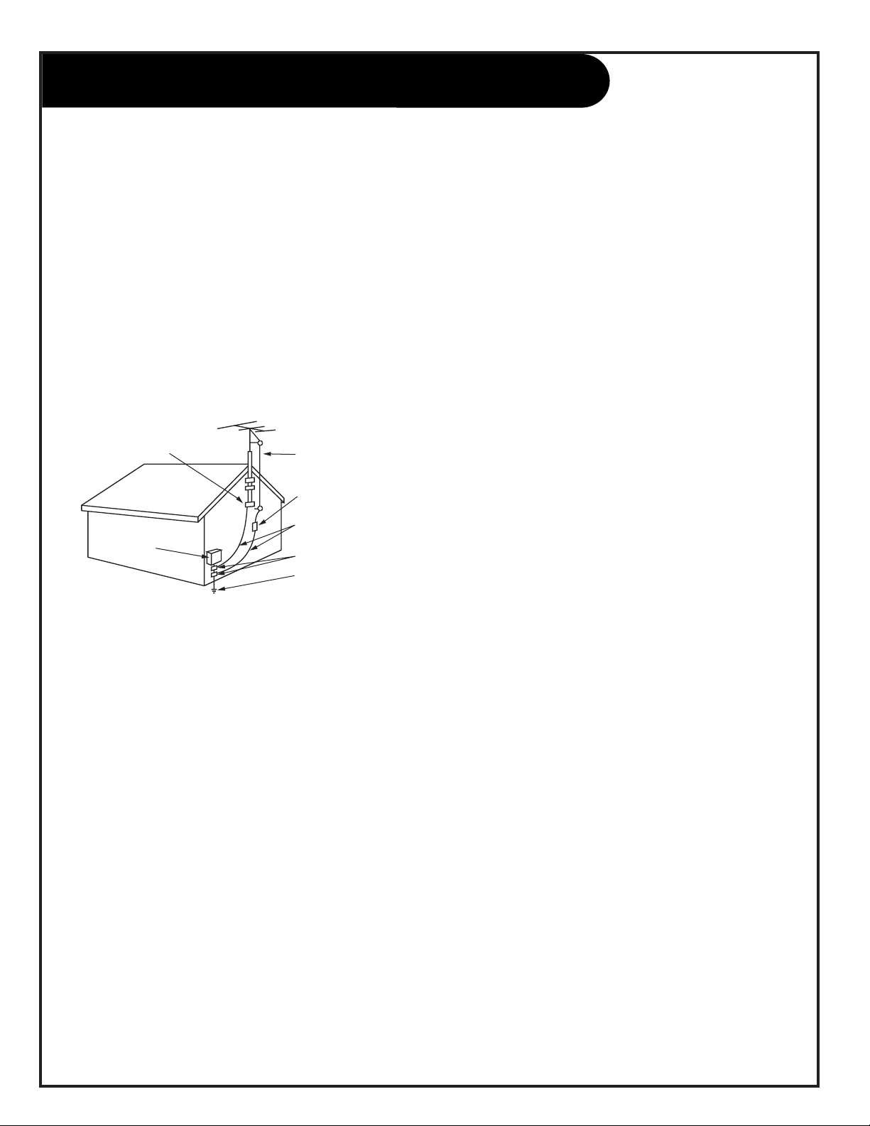
14. Outdoor Antenna Grounding
If an outside antenna or cable system is connected to the
product, be sure the antenna or cable system is grounded
so as to provide some protection against voltage surges
and built-up static charges. Article 810 of the National
Electrical Code (U.S.A.), ANSI/ NFPA 70 provides information with regard to proper grounding of the mast and supporting structure, grounding of the lead-in wire to an
antenna discharge unit, size of grounding conductors, location of antenna-discharge unit, connection to grounding
electrodes, and requirements for the grounding electrode.
15. Lightning
For added protection for this product (receiver) during a
lightning storm, or when it is left unattended and unused
for long periods of time, unplug it from the wall outlet and
disconnect the antenna or cable system. This will prevent
damage to the product due to lightning and power-line
surges.
16. Power Lines
An outside antenna system should not be located in the
vicinity of overhead power lines or other electric light or
power circuits, or where it can fall into such power lines or
circuits. When installing an outside antenna system,
extreme care should be taken to keep from touching such
power lines or circuits as contact with them might be
fatal.
17. Overloading
Do not overload wall outlets and extension cords as this
can result in a risk of fire or electric shock.
18. Object and Liquid Entry
Never push objects of any kind into this product through
openings as they may touch dangerous voltage points or
short-out parts that could result in a fire or electric shock.
Never spill liquid of any kind on the product.
19. Servicing
Do not attempt to service this product yourself as opening
or removing covers may expose you to dangerous voltage
or other hazards. Refer all servicing to qualified service
personnel.
20. Damage Requiring Service
Unplug this product from the wall outlet and refer servicing to qualified service personnel under the following conditions:
a. If the power-supply cord or plug is damaged.
b. If liquid has been spilled, or objects have fallen into
the product.
c. If the product has been exposed to rain or water.
d. If the product does not operate normally by following
the operating instructions. Adjust only those controls that
are covered by the operating instructions as an improper
adjustment of other controls may result in damage and will
often require extensive work by a qualified technician to
restore the product to its normal operation.
e. If the product has been dropped or the cabinet has
been damaged.
f. If the product exhibits a distinct change in performance.
21. Replacement Parts
When replacement parts are required, be sure the service
technician has used replacement parts specified by the
manufacturer or have the same characteristics as the original part. Unauthorized substitutions may result in fire,
electric shock, or other hazards.
22. Safety Check
Upon completion of any service or repairs to this product,
ask the service technician to perform safety checks to
determine that the product is in proper operating condition.
23. Wall or Ceiling Mounting
The product should be mounted to a wall or ceiling only as
recommended by the manufacturer.
24. Heat
The product should be situated away from heat sources
such as radiators, heat registers, stoves, or other products
(including amplifiers) that produce heat.
Antenna Lead in Wire
Antenna Discharge Unit
(NEC Section 810-20)
Grounding Conductor
(NEC Section 810-21)
Ground Clamps
Power Service Grounding
Electrode System (NEC
Art 250, Part H)
Ground Clamp
Electric Service
Equipment
Example of Grounding According to National Electrical
Code Instructions
NEC - National Electrical Code
IMPORTANT SAFETY INSTRUCTIONS

PAGE 5
206-3486-O
Table of Contents
Turn to the next page to begin the TV setup.
Safety Warnings . . . . . . . . . . . . . . . . . . . . . . . . . . . .2
Important Safety Information . . . . . . . . . . . . . . . . . . .3
Hookup Directory . . . . . . . . . . . . . . . . . . . . . . . . . . .6
Step 1. Hook Up TV
Rear Jack Panel . . . . . . . . . . . . . . . . . . . . . . . . . . . .7
Antenna and Cable Service . . . . . . . . . . . . . . . . . . . . .8
Antenna Loop Out with Cable Box . . . . . . . . . . . . . . . .9
VCR Hookup . . . . . . . . . . . . . . . . . . . . . . . . . . . . . .10
DVD and S-VHS VCR Hookup . . . . . . . . . . . . . . . . . . .11
Audio Speakers Hookup . . . . . . . . . . . . . . . . . . . . . .12
External Stereo Hookup . . . . . . . . . . . . . . . . . . . . . .13
Surround Sound Speaker Placement . . . . . . . . . . . . . .14
Step 2. Channel Search and Reception Setup
Basic Menu Navigation . . . . . . . . . . . . . . . . . . . . . . .15
Signal Source Selection and Auto Program . . . . . . . . . .16
(Select Antenna, or cable service and perform channel
search)
Remote Button Functions . . . . . . . . . . . . . . . . . . . . .17
On-Screen Displays . . . . . . . . . . . . . . . . . . . . . . . . .18
Front Panel Controls . . . . . . . . . . . . . . . . . . . . . . . .19
On-Screen Menus Overview . . . . . . . . . . . . . . . . . . . 20
Step 3. Customize your TV’s Features
Setup Menu
Language . . . . . . . . . . . . . . . . . . . . . . . . . . . . . . .22
Signal . . . . . . . . . . . . . . . . . . . . . . . . . . . . . . . . .16
Auto Program . . . . . . . . . . . . . . . . . . . . . . . . . . . .16
Channel Add/Delete . . . . . . . . . . . . . . . . . . . . . . . .23
Channel Review . . . . . . . . . . . . . . . . . . . . . . . . . . .24
Clock Set . . . . . . . . . . . . . . . . . . . . . . . . . . . . . . .25
Projo Setup . . . . . . . . . . . . . . . . . . . . . . . . . . . . . .26
Special Menu
Channel Labels . . . . . . . . . . . . . . . . . . . . . . . . . . . .27
Source ID . . . . . . . . . . . . . . . . . . . . . . . . . . . . . . .28
Favorite Channels . . . . . . . . . . . . . . . . . . . . . . . . . .29
Parental Control . . . . . . . . . . . . . . . . . . . . . . . . . . .30
Security Timer . . . . . . . . . . . . . . . . . . . . . . . . . . . .31
Captions/Text . . . . . . . . . . . . . . . . . . . . . . . . . . . .32
Background . . . . . . . . . . . . . . . . . . . . . . . . . . . . . .33
Video Menu . . . . . . . . . . . . . . . . . . . . . . . . . . . . .34
Audio Menu . . . . . . . . . . . . . . . . . . . . . . . . . . . . .35
Theater Menu . . . . . . . . . . . . . . . . . . . . . . . . . . . .36
Calender . . . . . . . . . . . . . . . . . . . . . . . . . . . . . . .37
Picture-In-Picture Overview . . . . . . . . . . . . . . . . . .38
Remote Control Programming . . . . . . . . . . . . . . . . . .41
Maintenance . . . . . . . . . . . . . . . . . . . . . . . . . . . . .44
Troubleshooting . . . . . . . . . . . . . . . . . . . . . . . . . . .46
Glossary . . . . . . . . . . . . . . . . . . . . . . . . . . . . . . . .48
Warranty . . . . . . . . . . . . . . . . . . . . . . . . . . . . . . .51
Note: Design and specifications are subject to change without prior notice.

PAGE 6
206-3486-O
For general information about the jacks on your Entertainment Machine, go to . . . . . . . . . page 7
If you are using an antenna or have direct cable service, go to . . . . . . . . . . . . . . . . . . . page 8
If you are using a cable box, go to . . . . . . . . . . . . . . . . . . . . . . . . . . . . . . . . . . . . . . page 9
If you are using a VCR, go to . . . . . . . . . . . . . . . . . . . . . . . . . . . . . . . . . . . . . . . . . page 10
If you are using a DVD Player, go to . . . . . . . . . . . . . . . . . . . . . . . . . . . . . . . . . . . . page 11
To hook up your surround sound speakers, mini tower speaker or sub-woofer, go to . . . . . page 12
To hook up your Entertainment Machine to an external stereo, go to . . . . . . . . . . . . . . . page 13
For general speaker placement advice, go to . . . . . . . . . . . . . . . . . . . . . . . . . . . . . . page 14
Hookup Directory
IMPORTANT!! Use this page to decide where you need to begin your setup.
First, find the line below that best describes what you want to do, then go to
that page number.
Antenna/Cable
Cable Box
VCR
DVD Player
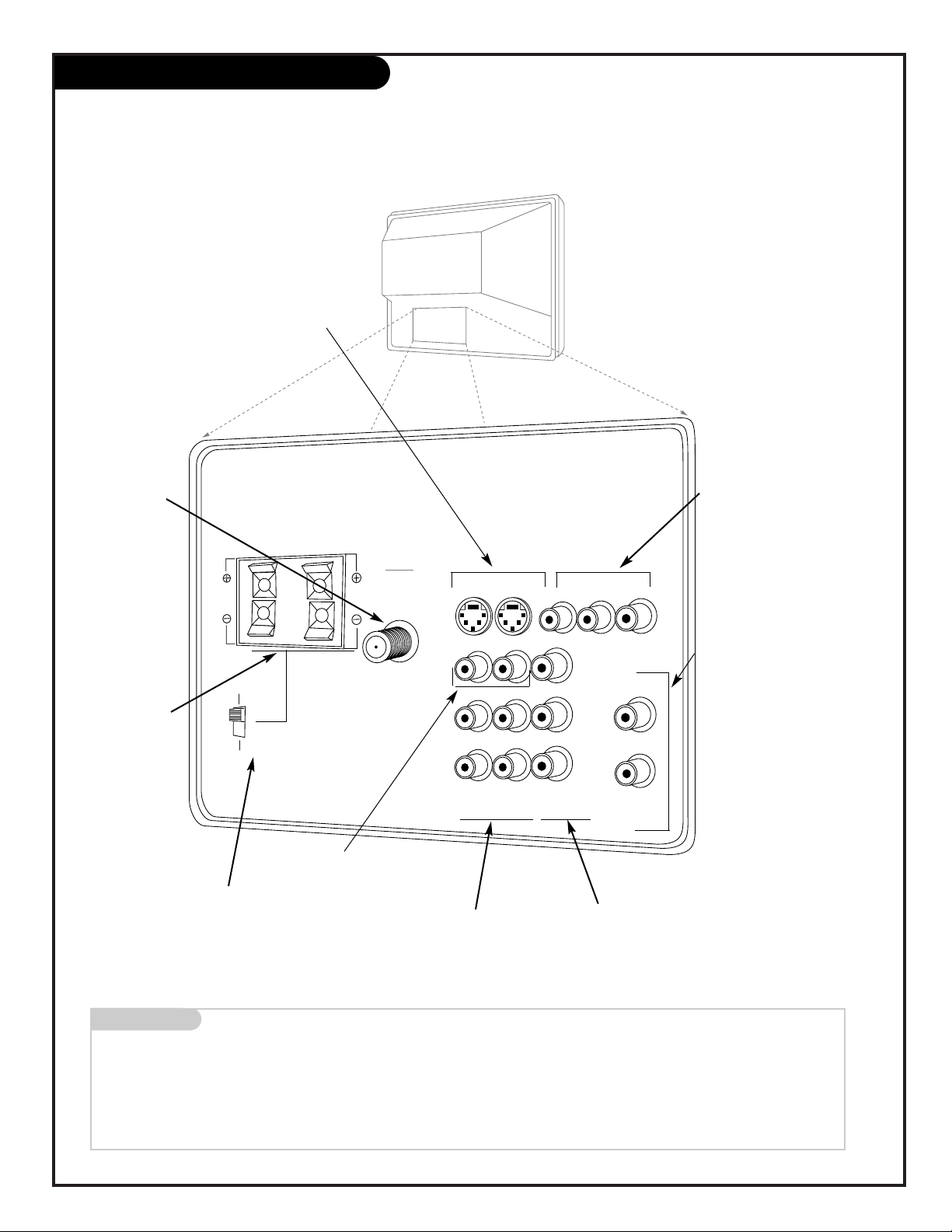
About your Jacks
Audio Speakers
Speaker Placement
External Stereo
INPUT HOOKUP OPTIONS
GENERAL HOOKUP INFORMATION
AUDIO EQUIPMENT OPTIONS
PAGE 7
Mini glossary
JACK A connection on the back of a TV, VCR, or any other A/V device. This includes the RF jack and the Audio/Video jacks that are color-
coded.
SIGNAL Picture and sound traveling through cable, or on the air, to your television screen.
VIDEO 2
S-VIDEO 2
INPUT 1
L/MONO
VIDEO 1
S-VIDEO 1
AUDIO
MONITOR OUT
VIDEO
RIGHT
LEFT
SURROUND / EXTERNAL SPEAKERS
8 ohm ONLY
ANTENNA
CABLE
INPUT
VARIABLE
AUDIO OUT
LEFT
RIGHT
AUDIO
AUDIO
RIGHT
RIGHT
RIGHT
LEFT
L/MONO
COMPONENT IN
( Y ) ( Cb )
( Cr )
INPUT 2
SURROUND
EXTERNAL
STOP
CONNECT ONLY 8 ohm SPEAKERS
DO NOT SHORT CIRCUIT
THESE TERMINALS
(Such damage is NOT COVERED
by your television warranty.)
Audio Video Jacks
S-VIDEO 1 or 2
A feature available
with some high-end
equipment that provides even better picture quality.
Variable Out
Used to connect
either an external
amplifier, or add a
sub-woofer to your
surround sound system.
RF Connectors:
Antenna/Cable
Used to connect cable
to the television, either
directly or through your
cable box.
Right/Left Audio
Used for stereo sound
from various types of
equipment.
Video 1 or 2
Connects the video
signals from various
types of equipment.
Y, Cb, Cr
Component Video
Some top-of-the-line DVD
players use what is
called “component video,”
for extremely accurate
picture reproduction.
Refer to your DVD manual
for further information.
Surround/External
Speaker Jacks
Right/Left
Used to improve your
sound by connecting
surround-sound
speakers.
Connecting cables to your Entertainment Machine.
Surround/External Speaker
Matrix Switch
Use this switch to choose
between the surround and
external speaker features.
206-3486-O
Monitor Out
These jacks provide
fixed audio and video
signals which are used
for recording.
PAGE 8
206-3486-O
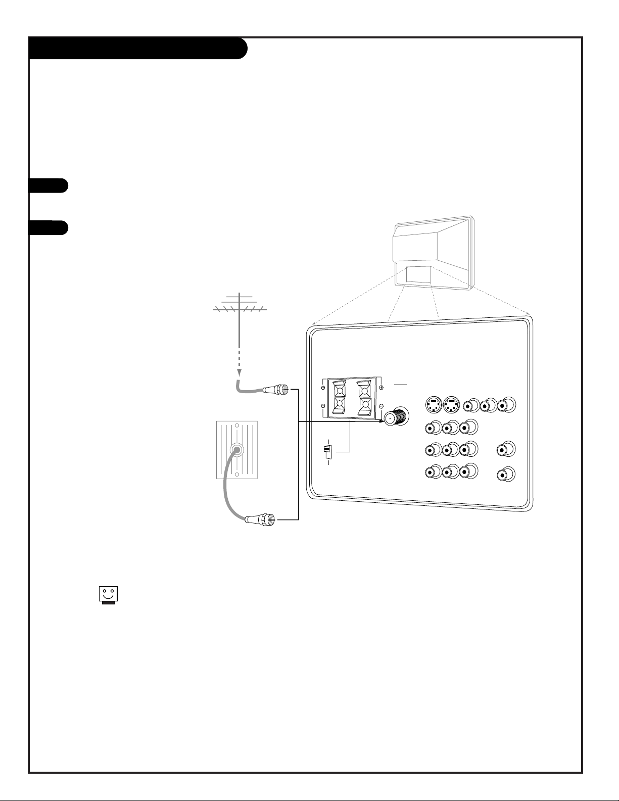
Hook Up Direct Cable TV or Antenna
RF coaxial wire
(75ohm)
Antenna
Cable TV
wall jack
Rf coaxial wire
(75ohm)
VIDEO 2
S-VIDEO 2
INPUT 1
L/MONO
VIDEO 1
S-VIDEO 1
AUDIO
MONITOR OUT
VIDEO
RIGHT
LEFT
SURROUND / EXTERNAL SPEAKERS
8 ohm ONLY
ANTENNA
CABLE
INPUT
VARIABLE
AUDIO OUT
LEFT
RIGHT
AUDIO
AUDIO
RIGHT
RIGHT
RIGHT
LEFT
L/MONO
COMPONENT IN
( Y ) ( Cb )
( Cr )
INPUT 2
SURROUND
EXTERNAL
STOP
CONNECT ONLY 8 ohm SPEAKERS
DO NOT SHORT CIRCUIT
THESE TERMINALS
(Such damage is NOT COVERED
by your television warranty.)
Locate the Antenna/Cable jack on
the back of your Entertainment
Machine.
Connect the cable that runs from
the wall directly to this jack.
1
2
If you receive cable through
an antenna that is several years
old and connects with two small
prongs, you will need to purchase
a 300 to 75Ohm adapter. It
should be available from your local
electronics dealer.
OR
PAGE 9
206-3486-O
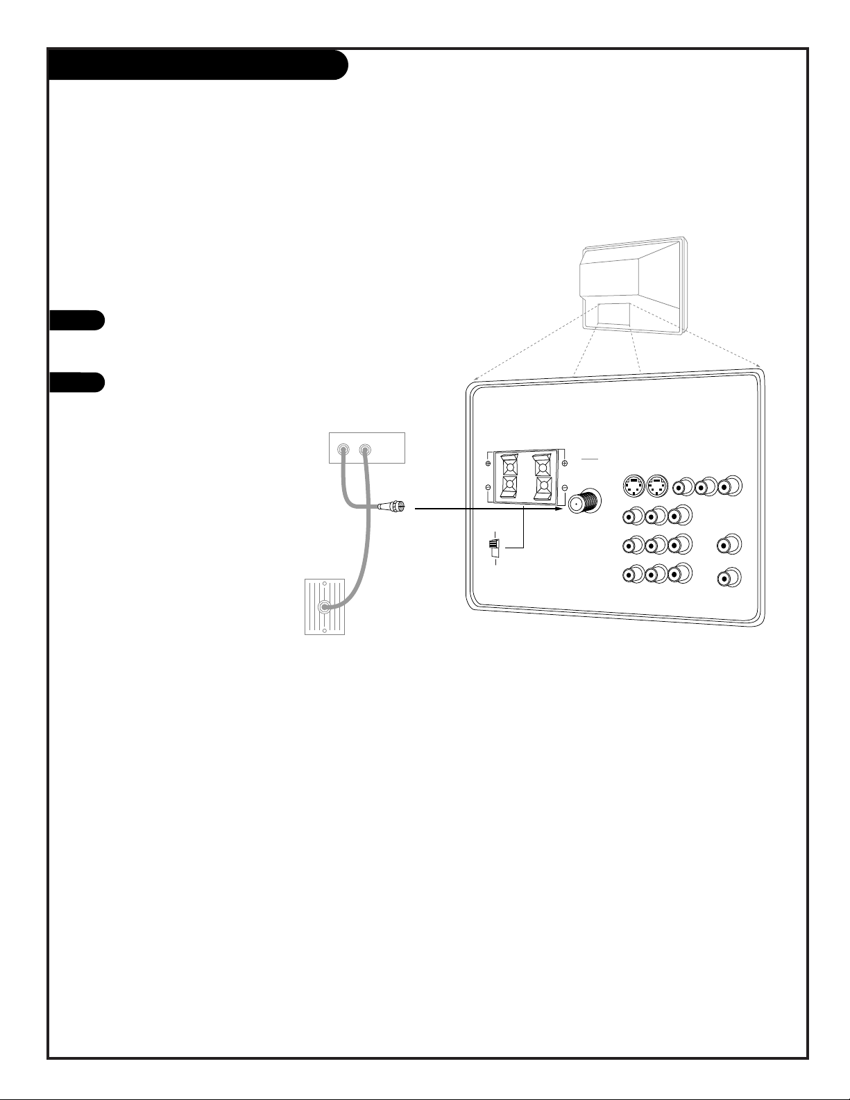
Cable Box
1
2
Cable TV
wall jack
Cable box
In
Out
Rf coaxial wire
(75ohm)
VIDEO 2
S-VIDEO 2
INPUT 1
L/MONO
VIDEO 1
S-VIDEO 1
AUDIO
MONITOR OUT
VIDEO
RIGHT
LEFT
SURROUND / EXTERNAL SPEAKERS
8 ohm ONLY
ANTENNA
CABLE
INPUT
VARIABLE
AUDIO OUT
LEFT
RIGHT
AUDIO
AUDIO
RIGHT
RIGHT
RIGHT
LEFT
L/MONO
COMPONENT IN
( Y ) ( Cb )
( Cr )
INPUT 2
SURROUND
EXTERNAL
STOP
CONNECT ONLY 8 ohm SPEAKERS
DO NOT SHORT CIRCUIT
THESE TERMINALS
(Such damage is NOT COVERED
by your television warranty.)
Locate the Antenna/Cable jack on
the back of your Entertainment
Machine.
Connect the cable that runs from
the wall to the IN jack on your
Cable Box. Connect the cable
from the OUT jack on your Cable
box to the Antenna/Cable jack on
your Entertainment Machine,
according to the diagram to the
right.
PAGE 10
206-3486-O
VIDEO 2
S-VIDEO 2
INPUT 1
L/MONO
VIDEO 1
S-VIDEO 1
AUDIO
MONITOR OUT
VIDEO
RIGHT
LEFT
SURROUND / EXTERNAL SPEAKERS
8 ohm ONLY
ANTENNA
CABLE
INPUT
VARIABLE
AUDIO OUT
LEFT
RIGHT
AUDIO
AUDIO
RIGHT
RIGHT
RIGHT
LEFT
L/MONO
COMPONENT IN
( Y ) ( Cb )
( Cr )
INPUT 2
SURROUND
EXTERNAL
STOP
CONNECT ONLY 8 ohm SPEAKERS
DO NOT SHORT CIRCUIT
THESE TERMINALS
(Such damage is NOT COVERED
by your television warranty.)
In
Out
Audio
Video
3 4
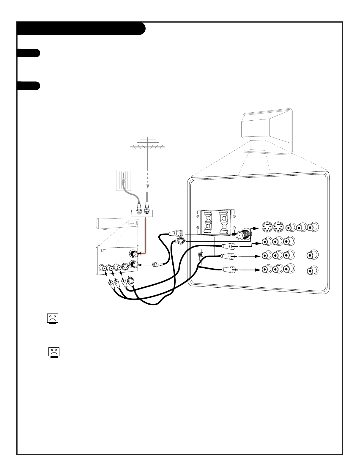
VCR
Back AV panel
A/V cables
not included
with TV
Cable TV
wall jack
Round wire
(75ohm)
RF coaxial wire
(75ohm)
Antenna
S-Video
OR
1
2
VCR
Locate the RF or VHF/UHF/CATV In jack on
the back of your VCR. Connect the cable
line coming from your wall directly to
this jack.
Find the composite video and audio
jacks on the back of your VCR, and connect them following the instructions
provided with your equipment.
You may connect either the composite
video or the S-video cables to your
Entertainment Machine. (Do not connect BOTH the composite and the SVideo cables. In the event that you
connect both composite and the SVideo cables, only the S-video will
work.)
To hear stereo sound from cable or your VCR,
you will need to connect A/V cables as well as
the wire that runs from the VCR to your
Entertainment Machine.
If you want to receive your signals on Channel
3 or 4, locate the Out to TV jack on your VCR.
Connect a cable from the Out to TV jack to the
Antenna/Cable jack on the back of your
Entertainment Machine.
PAGE 11
206-3486-O
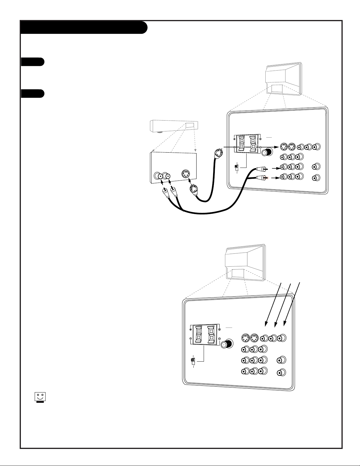
DVD Player
Find the audio and composite or S-Video
jacks on the back of your DVD Player and
connect them following the instructions
provided with your equipment.
You may connect either the composite
video or the S-Video cables to your
Entertainment Machine. (Do not connect
both the composite and the S-Video. In the
event that you connect both composite and
the S-Video cable, only the S-Video will
work.)
1
2
For several pieces of equipment,
edit the names under Source ID
so you don’t forget which is
which. See page 28.
Audio
LR
S-Video
A/V cables
not included
with TV
DVD Player
Back AV panel
VIDEO 2
S-VIDEO 2
INPUT 1
L/MONO
VIDEO 1
S-VIDEO 1
AUDIO
MONITOR OUT
VIDEO
RIGHT
LEFT
SURROUND / EXTERNAL SPEAKERS
8 ohm ONLY
ANTENNA
CABLE
INPUT
VARIABLE
AUDIO OUT
LEFT
RIGHT
AUDIO
AUDIO
RIGHT
RIGHT
RIGHT
LEFT
L/MONO
COMPONENT IN
( Y ) ( Cb )
( Cr )
INPUT 2
SURROUND
EXTERNAL
STOP
CONNECT ONLY 8 ohm SPEAKERS
DO NOT SHORT CIRCUIT
THESE TERMINALS
(Such damage is NOT COVERED
by your television warranty.)
Some high-end DVD players use a picture reproduction system called “component video.” If
your DVD player has component output, use the
connectors marked “DVD” on the jack panel.
Please refer to your DVD manual for proper
installation.
If you have a DVD Player
with Component Video, use
these jacks marked Y, Cb, and Cr.
VIDEO 2
S-VIDEO 2
INPUT 1
L/MONO
VIDEO 1
S-VIDEO 1
AUDIO
MONITOR OUT
VIDEO
RIGHT
LEFT
SURROUND / EXTERNAL SPEAKERS
8 ohm ONLY
ANTENNA
CABLE
INPUT
VARIABLE
AUDIO OUT
LEFT
RIGHT
AUDIO
AUDIO
RIGHT
RIGHT
RIGHT
LEFT
L/MONO
COMPONENT IN
( Y ) ( Cb )
( Cr )
INPUT 2
SURROUND
EXTERNAL
STOP
CONNECT ONLY 8 ohm SPEAKERS
DO NOT SHORT CIRCUIT
THESE TERMINALS
(Such damage is NOT COVERED
by your television warranty.)
PAGE 12
206-3486-O
1
2
3
1
2
VIDEO 2
S-VIDEO 2
INPUT 1
S-VIDEO
L/MONO
VIDEO 1
S-VIDEO 1
AUDIO
MONITOR OUT
VIDEO
RIGHT
SURROUND / EXTERNAL SPEAKERS
8 ohm ONLY
LOOP OUT
ANTENNA
CABLE 1
ANTENNA
CABLE 2
INPUT
INPUT
VARIABLE
AUDIO OUT
LEFT
RIGHT
AUDIO
AUDIO
RIGHT
RIGHT
RIGHT
LEFT
L/MONO
COMPONENT IN
( Y ) ( Cb )
( Cr )
INPUT 2
SURROUND
EXTERNAL
STOP
CONNECT ONLY 8 ohm SPEAKERS
DO NOT SHORT CIRCUIT
THESE TERMINALS
(Such damage is NOT COVERED
by your television warranty.)
Audio cables
not included
with TV
Sub-woofer
LEFT
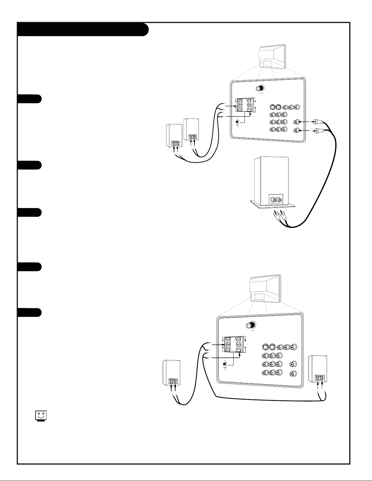
Audio Hookups
Locate the Surround/External
Speaker clips on the back of your
Entertainment Machine. Connect
the wires to the right or left
speaker clips, depending on
where the speaker is located in
your room. The copper wire corresponds to the Negative jack, and
the silver to the Positive.
Locate the jacks marked Variable
Out. These are for the sub-woofer.
Connect the sub-woofer’s cables,
according to their color (red is
the right channel, white the left)
to these jacks.
Set the Surround/External Speaker
Matrix switch into the “External”
position.
To use your Surround/External
Speaker clips as the only audio
output, connect the wires for
your speakers to the Surround
Speaker clips according to the
diagram on the right.
Set the Surround/External Speaker
Matrix switch into the “External”
position.
If you happen to have Mini-tower
speakers, these will be connected
to the back of your sub-woofer,
with the jack labeled Satellite
Speaker Output.
Before you begin connecting your speakers, it’s a good idea to put
them in their approximate places first. That way you know how
much wire you have or will need.
VIDEO 2
S-VIDEO 2
INPUT 1
S-VIDEO
L/MONO
VIDEO 1
S-VIDEO 1
AUDIO
MONITOR OUT
VIDEO
RIGHT
SURROUND / EXTERNAL SPEAKERS
8 ohm ONLY
LOOP OUT
ANTENNA
CABLE 1
ANTENNA
CABLE 2
INPUT
INPUT
VARIABLE
AUDIO OUT
LEFT
RIGHT
AUDIO
AUDIO
RIGHT
RIGHT
RIGHT
LEFT
L/MONO
COMPONENT IN
( Y ) ( Cb )
( Cr )
INPUT 2
SURROUND
EXTERNAL
STOP
CONNECT ONLY 8 ohm SPEAKERS
DO NOT SHORT CIRCUIT
THESE TERMINALS
(Such damage is NOT COVERED
by your television warranty.)
Right
Left
LEFT
Hook up Left/Right Front Speaker to Amplifier System.
Hook up Left/Right Front Speaker to Amplifier System.
PAGE 13
206-3486-O
1
2
3
4
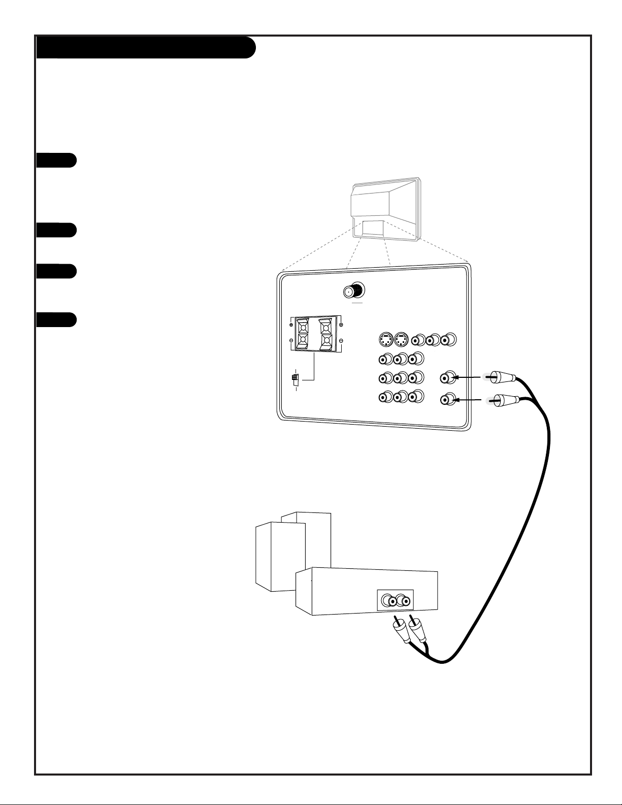
External Stereo
External stereo amplifier
VIDEO 2
S-VIDEO 2
INPUT 1
S-VIDEO
L/MONO
VIDEO 1
S-VIDEO 1
AUDIO
MONITOR OUT
VIDEO
RIGHT
SURROUND / EXTERNAL SPEAKERS
8 ohm ONLY
ANTENNA
CABLE 1
LOOP OUT
ANTENNA
CABLE 2
INPUT
INPUT
VARIABLE
AUDIO OUT
LEFT
RIGHT
AUDIO
AUDIO
RIGHT
RIGHT
RIGHT
LEFT
L/MONO
COMPONENT IN
( Y ) ( Cb )
( Cr )
INPUT 2
SURROUND
EXTERNAL
STOP
CONNECT ONLY 8 ohm SPEAKERS
DO NOT SHORT CIRCUIT
THESE TERMINALS
(Such damage is NOT COVERED
by your television warranty.)
Audio cables
not included
with TV
LEFT
Locate the Variable Out jacks on
the back of your Entertainment
Machine and the Input jacks on
the back of your stereo's amplifier.
Connect the two jacks, making
sure that the right and left channels are placed correctly.
Set up your speakers through
your stereo, according to those
directions.
Turn off the internal speakers
through the Audio Menu. See
page 36.
Hook up Left/Right Front Speaker to Amplifier System.
PAGE 14
206-3486-O
Mini glossary
AMPLIFIER An external device that amplifies sound from a television, CD player, VCR, DVD or other A/V device.
General help on designing your home theater set-up.
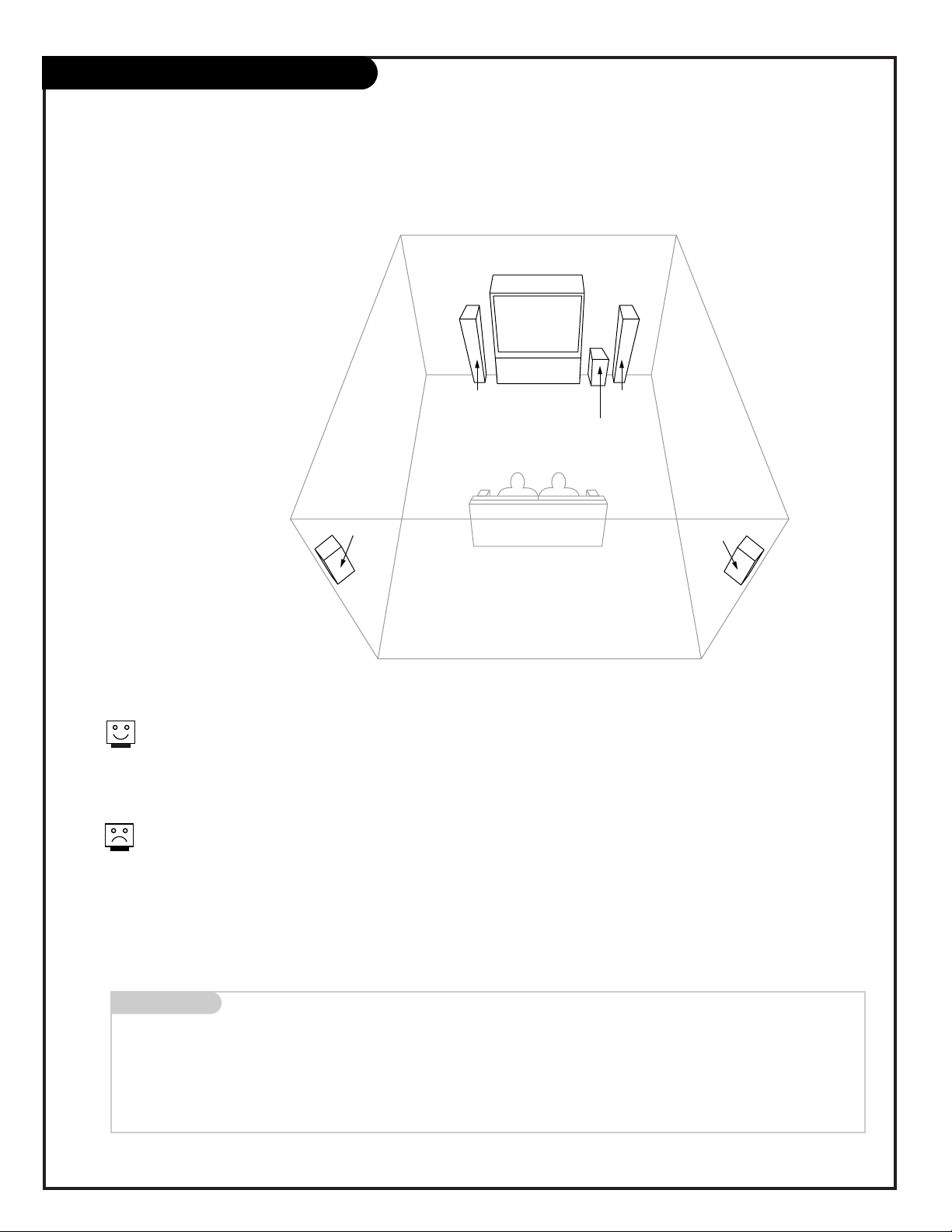
Room Set-ups for Home Theater
sub-woofer
right
speaker
left
speaker
surround
sound
speaker
surround
sound
speaker
This is just a general room design.
Any number of set-ups are possible,
and some changes may be needed to
maximize your sound.
A left and right speaker on either
side of the Entertainment Machine
will create a “center channel,” making
the dialog sound as though it’s
coming directly from the
Entertainment Machine.
The rear surround sound speakers
provide the majority of other sounds,
like those from special effects in
movies. Your sub-woofer generates
ultra-low frequency sound, for
rumbling low-end audio.
Sound is affected by
speaker placement, so make
sure nothing is in front of the
speakers, and that they are
aimed in appropriate directions.
If your surround sound system
is on, but there’s no sound
from the speakers, the program
you’re watching might not be
broadcast in surround sound.
PAGE 15
206-3486-O
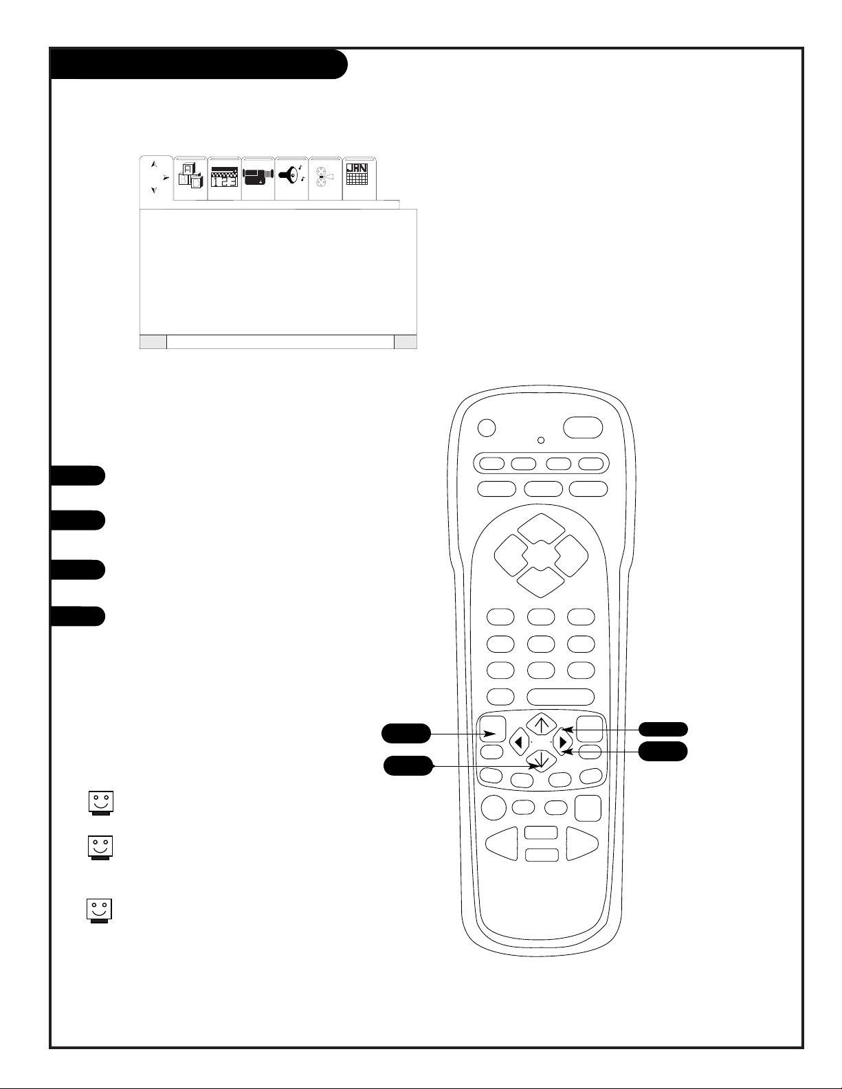
Menu Navigation
Press the Menu to access the onscreen Menu.
Press a LEFT/RIGHT arrow button
to select the Menu you want.
Press an UP/DOWN arrow to select
a Menu Item to adjust.
Press a RIGHT/LEFT arrow button
to activate the Menu Item you
wish to adjust.
prg
power
tv vcr cable help
source
display
flashbk mute
channel
channel
volume volume
123
456
7
0
89
rewind f. fwd.
record
pip
swap
freez
move
tv/vcr
pause timer
play
stop
menu
quit
fav
ch
pip ch c.skip
This page explains the first four steps you should perform to access any menu
described in this manual.
1
2
3
4
1
Language
Signal
Auto Program
Channel Add/Del
Channel Review
Clock Set
Projo Setup
SMTWTF S
Setup Video Audio Theater Calendr
To Exit QuitTo Menu BarMenu
Special
2
3
4
Press QUIT to exit the menu screen at any
time.
Press MENU to return to MENU cycle
through the Setup, Special, Video, Audio,
Theater and Calendar menus.
Press QUIT to set your menu selections and
return to TV viewing.
PAGE 16
206-3486-O
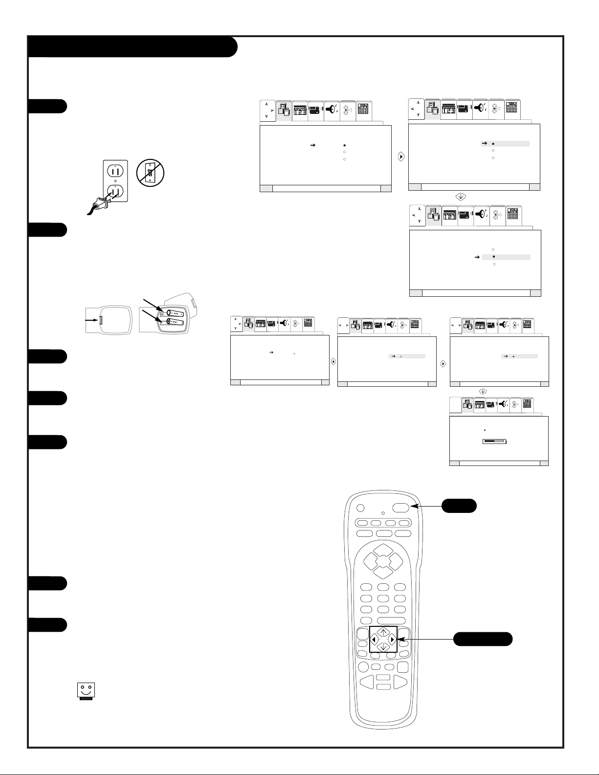
1
2
3
4
5
6
7
Signal source selection:
Setup
Use pages 7-13 to hook up your
Entertainment Machine. Plug in
your Entertainment Machine into
a 120V 60Hz outlet.
Remove the back of the remote
and put in two AAA batteries.
Make sure batteries are properly
installed (check the +/– signs).
Turn on your Entertainment
Machine by pressing the POWER
button on your remote.
Access the Signal item on your
Setup Menu by following the four
steps on page 15.
Select the signal source of your
Entertainment Machine. If your
signal comes from an outdoor
antenna, select ANTENNA by
pressing the RIGHT arrow button.
If your signal comes from a cable
TV service, select CATV 1 by pressing the DOWN arrow button, then
the RIGHT arrow button. When
you have made your selection,
press the MENU button to return
to the Setup Menu.
Now access the Auto Program
Menu Item by pressing the DOWN
arrow button on your remote.
Press the RIGHT arrow button to
select Auto Program and then
press the RIGHT arrow button
again to begin Auto
Programming.
prg
power
tv vcr cable help
source
display
flashbk mute
channel
channel
volume volume
123
456
7089
rewind f. fwd.
record
pip
swap
freez
move
tv/vcr
pause timer
play
stop
menu
quit
fav
ch
pip ch c.skip
SMTWTFS
SMTWTFS
SMTWTFS
VideoSetup Special Audio Theater Calendr
Language
Signal Antenna
Auto Program CATV 1
Channel Add/Del CATV 2
Channel Review
Clock Set
Projo Setup
VideoSetup Special Audio Theater Calendr
Language
Signal Antenna
Auto Program CATV 1
Channel Add/Del CATV 2
Channel Review
Clock Set
Projo Setup
VideoSetup Special Audio Theater Calendr
Language
Signal Antenna
Auto Program CATV 1
Channel Add/Del CATV 2
Channel Review
Clock Set
Projo Setup
QuitTo ExitTo Menu BarMenu
QuitTo ExitTo Menu BarMenu
QuitTo ExitTo Menu BarMenu
3
Language
Signal
Auto Program Begin
Channel Add/Del
Channel Review
Clock Set
Projo Setup
SMTWTFS
SMTWTFS
SMTWTFS
INSTALLING
CHANNEL 110
50% COMPLETE
SMTWTFS
VideoSetup Special Audio Theater
VideoSetup Special Audio Theater
VideoSetup Special Audio Theater Calendr
VideoSetup Special Audio Theater Calendr
Language
Signal
Auto Program Begin
Channel Add/Del
Channel Review
Clock Set
Projo Setup
Language
Signal
Auto Program Begin
Channel Add/Del
Channel Review
Clock Set
Projo Setup
Calendr
Calendr
QuitTo ExitTo Menu BarMenu
QuitTo ExitTo Menu BarMenu QuitTo ExitTo Menu BarMenu
QuitTo ExitTo Menu BarMenu
Auto Program:
back of
remote
5/6/7
If certain CATV channel are poor
or not possible in CATV1 mode,
set signal to CATV2 mode.
 Loading...