

page
6
machine numbers IQB27B42W IQB32B42W IQB36B42W
IQB32B84R IQB32B86R IQB36B86R
operating guide / warranty
hookup directory
glossary
your on-screen menus
page
52
page
18
table of contents
page
5
WARNING
:
TO REDUCE THE RISK OF ELECTRIC SHOCK DO NOT REMOVE COVER (OR BACK). NO USER SERVICEABLE PARTS INSIDE.
REFER SERVICING TO QUALIFIED SERVICE PERSONNEL.
The lightning flash with arrowhead symbol, within an equilateral triangle, is intended to alert the user to the presence
of uninsulated “dangerous voltage” within the product’s enclosure that may be of sufficient magnitude to constitute a
risk of electric shock to persons.
The exclamation point within an equilateral triangle is intended to alert the user to the presence of important operating
and maintenance (servicing) instructions in the literature accompanying the appliance.
WARNING:
TO PREVENT FIRE OR SHOCK HAZARDS, DO NOT EXPOSE THIS PRODUCT TO RAIN OR MOISTURE.
POWER CORD POLARIZATION:
CAUTION: To prevent electric shock, match wide blade of plug to wide slot, fully insert.
ATTENTION: Pour éviter les chocs électriques, introduire la lame la plus large de la fiche dans la borne
correspondante de la prise et pousser jusqu’au fond.
NOTE TO CABLE/TV INSTALLER:
This reminder is provided to call the cable TV system installer’s attention to Article 820-40 of the National Electric Code
(U.S.A.). The code provides guidelines for proper grounding and, in particular, specifies that the cable ground shall be
connected to the grounding system of the building, as close to the point of the cable entry as practical.
REGULATORY INFORMATION:
This equipment has been tested and found to comply with the limits for a Class B digital device, pursuant to Part 15
of the FCC Rules. These limits are designed to provide reasonable protection against harmful interference when the
equipment is operated in a residential installation. This equipment generates, uses and can radiate radio frequency
energy and, if not installed and used in accordance with the instruction manual, may cause harmful interference to radio
communications. However, there is no guarantee that interference will not occur in a particular installation. If this
equipment does cause harmful interference to radio or television reception, which can be determined by turning
the equipment off and on, the user is encouraged to try to correct the interference by one or more of the following
measures:
• Reorient or relocate the receiving antenna.
• Increase the separation between the equipment and receiver.
• Connect the equipment into an outlet on a circuit different from that to which the
receiver is connected.
• Consult the dealer or an experienced radio/TV technician for help.
CAUTION:
Do not attempt to modify this product in any way without written authorization from Zenith Electronics Corporation.
Unauthorized modification could void the user’s authority to operate this product.
RECORD YOUR MODEL NUMBER
(Now, while you can see it)
The model and serial number of your new TV are located
on the back of the TV cabinet. For your future convenience,
we suggest that your record these numbers here:
MODEL NO.____________________________________
SERIAL NO.____________________________________
WARNING
RISK OF ELECTRIC SHOCK
DO NOT OPEN
B-WARN-DV-1 7/98
PAGE 2

206-3481
PAGE 3
Important safeguards for you and your new product
Your product has been manufactured and tested with your safety in mind. However, improper use can result in potential
electrical shock or fire hazards. To avoid defeating the safeguards that have been built into your new product, please read
and observe the following safety points when installing and using your new product, and save them for future reference.
Observing the simple precautions discussed in this operating guide can help you get many years of enjoyment and safe
operation that are built into your new product.
This product complies with all applicable U.S. Federal safety requirements, and those of the Canadian Standards Association.
(Continued on next page)
1. Read Instructions
All the safety and operating instructions should be read
before the product is operated.
2. Follow Instructions
All operating and use instructions should be followed.
3. Retain Instructions
The safety and operating instructions should be retained
for future reference.
4. Heed Warnings
All warnings on the product and in the operating instructions should be adhered to.
5. Cleaning
Unplug this product from the wall outlet before cleaning.
Do not use liquid cleaners or aerosol cleaners. Use a damp
cloth for cleaning.
6. Water and Moisture
Do not use this product near water for example, near a
bath tub, wash bowl, kitchen sink, or laundry tub, in a
wet basement, or near a swimming pool.
7. Accessories
Do not place this product on an unstable cart, stand,
tripod, bracket, or table. The product may fall, causing
serious injury to a child or adult, and serious damage to
the product. Use only with a cart, stand, tripod, bracket,
or table recommended by the manufacturer, or sold with
the product. Any mounting of the product should follow
the manufacturer’s instructions, and should use a
mounting accessory recommended by the manufacturer.
8. Transporting Product
A product and cart combination should be moved with
care. Quick stops, excessive force, and uneven surfaces
may cause the product and cart combination to overturn.
9. Attachments
Do not use attachments not recommended by the product
manufacturer as they may cause hazards.
10. Ventilation
Slots and openings in the cabinet are provided for
ventilation and to ensure reliable operation of the product
and to protect it from overheating, and these openings
must not be blocked or covered. The openings should
never be blocked by placing the product on a bed, sofa,
rug, or other similar surface. This product should not be
placed in a built-in installation such as a bookcase or rack
unless proper ventilation is provided or the manufacturer’s
instructions have been adhered to.
11. Power Sources
This product should be operated only from the type of
power source indicated on the marking label. If you are
not sure of the type of power supply to your home,
consult your product dealer or local power company. For
products intended to operate from battery power, or other
sources, refer to the operating instructions.
12. Line-Cord Polarization
This product is equipped with a polarized
alternating-current line plug (a plug having one blade
wider than the other). This plug will fit into the power
outlet only one way. This is a safety feature. If you are
unable to insert the plug fully into the outlet, try
reversing the plug. If the plug should still fail to fit,
contact your electrician to replace your obsolete outlet.
Do not defeat the safety purpose of the polarized plug.
13. Power-Cord Protection
Power-supply cords should be routed so that they are not
likely to be walked on or pinched by items placed upon or
against them, paying particular attention to cords at
plugs, convenience receptacles, and the point where they
exit from the product.
IMPORTANT SAFETY INSTRUCTIONS
206-3481
PAGE 4
(Continued from previous page)
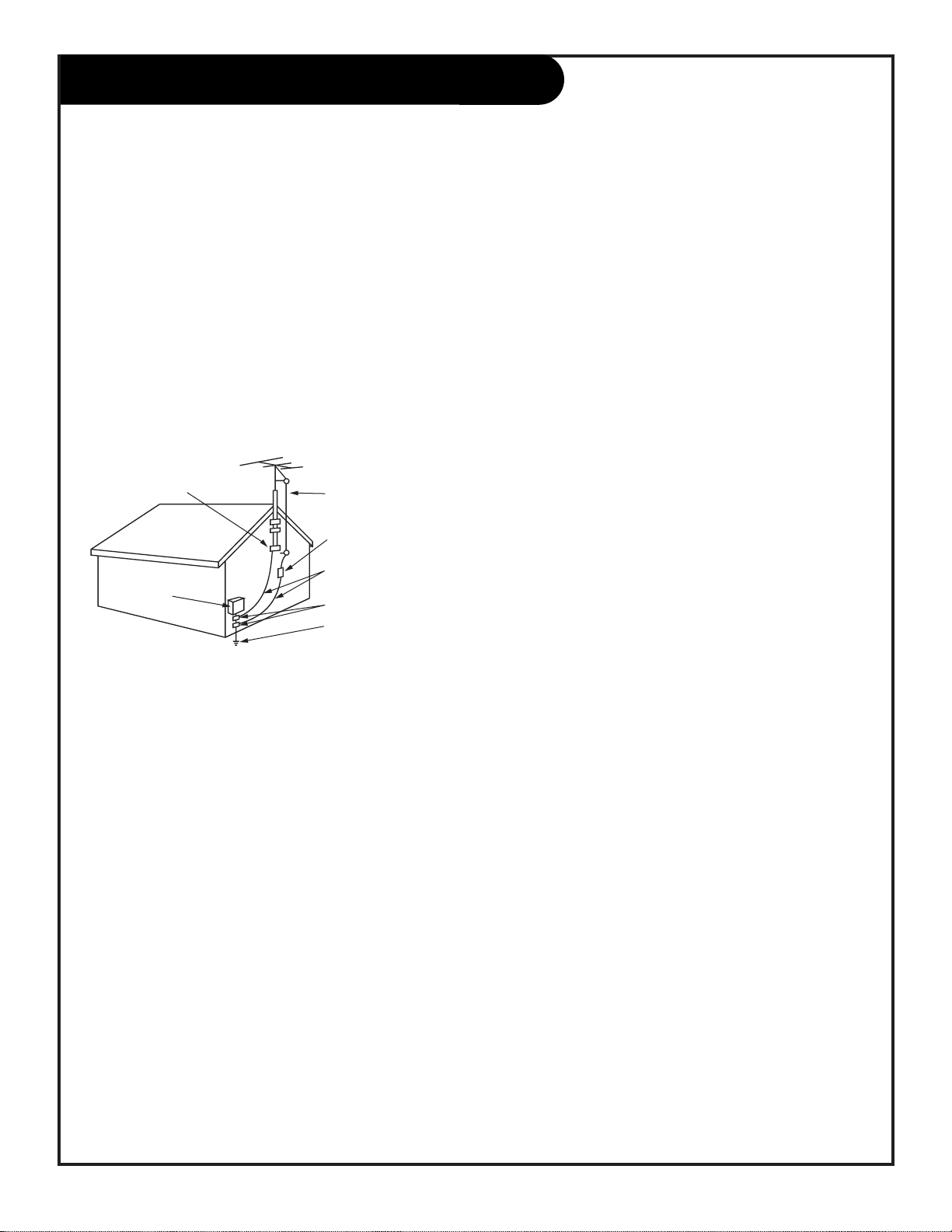
14. Outdoor Antenna Grounding
If an outside antenna or cable system is connected to the
product, be sure the antenna or cable system is grounded
so as to provide some protection against voltage surges
and built-up static charges. Article 810 of the National
Electrical Code (U.S.A.), ANSI/ NFPA 70 provides
information with regard to proper grounding of the mast
and supporting structure, grounding of the lead-in wire to
an antenna discharge unit, size of grounding conductors,
location of antenna-discharge unit, connection to
grounding electrodes, and requirements for the grounding
electrode.
15. Lightning
For added protection for this product (receiver) during a
lightning storm, or when it is left unattended and unused
for long periods of time, unplug it from the wall outlet and
disconnect the antenna or cable system. This will prevent
damage to the product due to lightning and power-line
surges.
16. Power Lines
An outside antenna system should not be located in the
vicinity of overhead power lines or other electric light or
power circuits, or where it can fall into such power lines or
circuits. When installing an outside antenna system,
extreme care should be taken to keep from touching such
power lines or circuits as contact with them might be
fatal.
17. Overloading
Do not overload wall outlets and extension cords as this
can result in a risk of fire or electric shock.
18. Object and Liquid Entry
Never push objects of any kind into this product through
openings as they may touch dangerous voltage points or
short-out parts that could result in a fire or electric shock.
Never spill liquid of any kind on the product.
19. Servicing
Do not attempt to service this product yourself as opening
or removing covers may expose you to dangerous voltage
or other hazards. Refer all servicing to qualified service
personnel.
20. Damage Requiring Service
Unplug this product from the wall outlet and refer servicing to qualified service personnel under the following
conditions:
a. If the power-supply cord or plug is damaged.
b. If liquid has been spilled, or objects have fallen into
the product.
c. If the product has been exposed to rain or water.
d. If the product does not operate normally by following
the operating instructions. Adjust only those controls that
are covered by the operating instructions as an improper
adjustment of other controls may result in damage and will
often require extensive work by a qualified technician to
restore the product to its normal operation.
e. If the product has been dropped or the cabinet has
been damaged.
f. If the product exhibits a distinct change in
performance.
21. Replacement Parts
When replacement parts are required, be sure the service
technician has used replacement parts specified by the
manufacturer or have the same characteristics as the
original part. Unauthorized substitutions may result in fire,
electric shock, or other hazards.
22. Safety Check
Upon completion of any service or repairs to this product,
ask the service technician to perform safety checks to
determine that the product is in proper operating
condition.
23. Wall or Ceiling Mounting
The product should be mounted to a wall or ceiling only as
recommended by the manufacturer.
24. Heat
The product should be situated away from heat sources
such as radiators, heat registers, stoves, or other products
(including amplifiers) that produce heat.
Antenna Lead in Wire
Antenna Discharge Unit
(NEC Section 810-20)
Grounding Conductor
(NEC Section 810-21)
Ground Clamps
Power Service Grounding
Electrode System (NEC
Art 250, Part H)
Ground Clamp
Electric Service
Equipment
Example of Grounding According to National Electrical
Code Instructions
NEC - National Electrical Code
IMPORTANT SAFETY INSTRUCTIONS
206-3482
PAGE 5
Turn to the next page to setup your Entertainment Machine
TM
Table Of Contents
Features on this TV also include:
Parental Control - Restricts programs which can appear on your TV, see page 28.
PIP - 2-Tuner Picture-in-Picture, see page 40.
Programmable Remote Control - Remote may control up to 7 products, see page 43.
V-CHIP Plus+ - Kid’s TV, Block, and Watch options using the program’s VCR+ PlusCodes, see page 35.
XDS Display - Extended Data Service. Shows current program information, see page 27.
EZ Features: Designed to make your viewing experience less work; see the EZ Help menu on page 54.
EZ Program Finds channels in your area automatically.
EZ Timer Sets times to turn the TV on and off.
EZ Picture Customizes video level settings.
EZ Demo Shows menus and displays on this TV.
EZ SoundRite Maintains and even sound level.
EZ Mute Turns sound off, while picture remains.
Note: Design and specifications are subject to change without prior notice.
Safety Warnings . . . . . . . . . . . . . . . . . . . . . . . . . . . 2
Important Safety Instructions . . . . . . . . . . . . . . . 3 - 4
Table of Contents . . . . . . . . . . . . . . . . . . . . . . . . . . 5
Step 1. Hook Up TV
Hookup Directory . . . . . . . . . . . . . . . . . . . . . . . . . 6
TV and other Equipment Hookups
Antenna . . . . . . . . . . . . . . . . . . . . . . . . . . . . . . 7
Cable service . . . . . . . . . . . . . . . . . . . . . . . . . . . 8
Antenna with VCR . . . . . . . . . . . . . . . . . . . . . . . 9
Cable service with VCR . . . . . . . . . . . . . . . . . . . . 10
Super VHS VCR/Digital Video Disk Player . . . . . . . . 11
Audio Equipment: Stereo . . . . . . . . . . . . . . . . . . 12
Step 2. Channel Search and Reception Setup . .
EZ Program . . . . . . . . . . . . . . . . . . . . . . . . . . . . . 13
(Select Antenna, or cable service and perform channel
search)
Remote Control TV Mode Key Functions . . . . . . . . . . . 14
Remote On-Screen Menu Operation . . . . . . . . . . . . . . 15
Front Panel Controls . . . . . . . . . . . . . . . . . . . . . . . 16
Basic TV Operation, Tuners and Picture Sources . . . . 17
On-Screen Menus/Displays Overview . . . . . . . . . . . . . 18
On-Screen Displays . . . . . . . . . . . . . . . . . . . . . . . . 19
Step 3. Customize Your TV’s Features
Setup Menu (Starts with page 13, EZ Program)
Add/Del/Surf . . . . . . . . . . . . . . . . . . . . . . . . . . 20
Clock Set . . . . . . . . . . . . . . . . . . . . . . . . . . . . 21
Captions, Caption/Text . . . . . . . . . . . . . . . . . . . . 22
Language . . . . . . . . . . . . . . . . . . . . . . . . . . . . 23
Special Features Menu
EZ Timer Setup, Sleep Timer . . . . . . . . . . . . . . . . 24
On and Off Time, On/Off Timer . . . . . . . . . . . . . . 25
Channel Labels . . . . . . . . . . . . . . . . . . . . . . . . . 26
XDS Display . . . . . . . . . . . . . . . . . . . . . . . . . . . 27
Parental Control . . . . . . . . . . . . . . . . . . . . 28 - 29
EZ Demo (On-screen menus overview) . . . . . . . . . . 30
Audio Menu . . . . . . . . . . . . . . . . . . . . . . . . . . . . 31
Bass, Treble, Balance, Audio Mode,
Front Surround, Sound Rite, Speakers
Video Menu . . . . . . . . . . . . . . . . . . . . . . . . . . . . 32
Contrast, Brightness, Color, Tint, Sharpness, Color Temp,
EZ Picture
PIP Menu . . . . . . . . . . . . . . . . . . . . . . . . . . . . . 33
Contrast, Tint, Size
Source Menu . . . . . . . . . . . . . . . . . . . . . . . . . . . . 34
Main Screen Picture, PIP Inset Picture
V-CHIP Plus+ Demo, Setup, Overview, and Operation
Kid’s TV, Block, Watch . . . . . . . . 35 - 36 - 37- 38 - 39
PIP (Picture-in-Picture) . . . . . . . . . . . . . - 40 - 41 - 42
Overview, and Operation
Remote Control Programming . . . . . . . . . . . . . . 43 - 49
Maintenance . . . . . . . . . . . . . . . . . . . . . . . . . . . . 50
Trouble Shooting . . . . . . . . . . . . . . . . . . . . . . 51 - 52
Glossary . . . . . . . . . . . . . . . . . . . . . . . . . . . . . . . 53
EZ Help Menu . . . . . . . . . . . . . . . . . . . . . . . . . . . 54
Zenith Accessory Products . . . . . . . . . . Inside Back Cover
Warranty . . . . . . . . . . . . . . . . . . . . . . . . . Back Cover
Entertainment MachineTMis a trademark of Zenith Electronics Corporation.
Hookup Directory
206-3375
PAGE 6
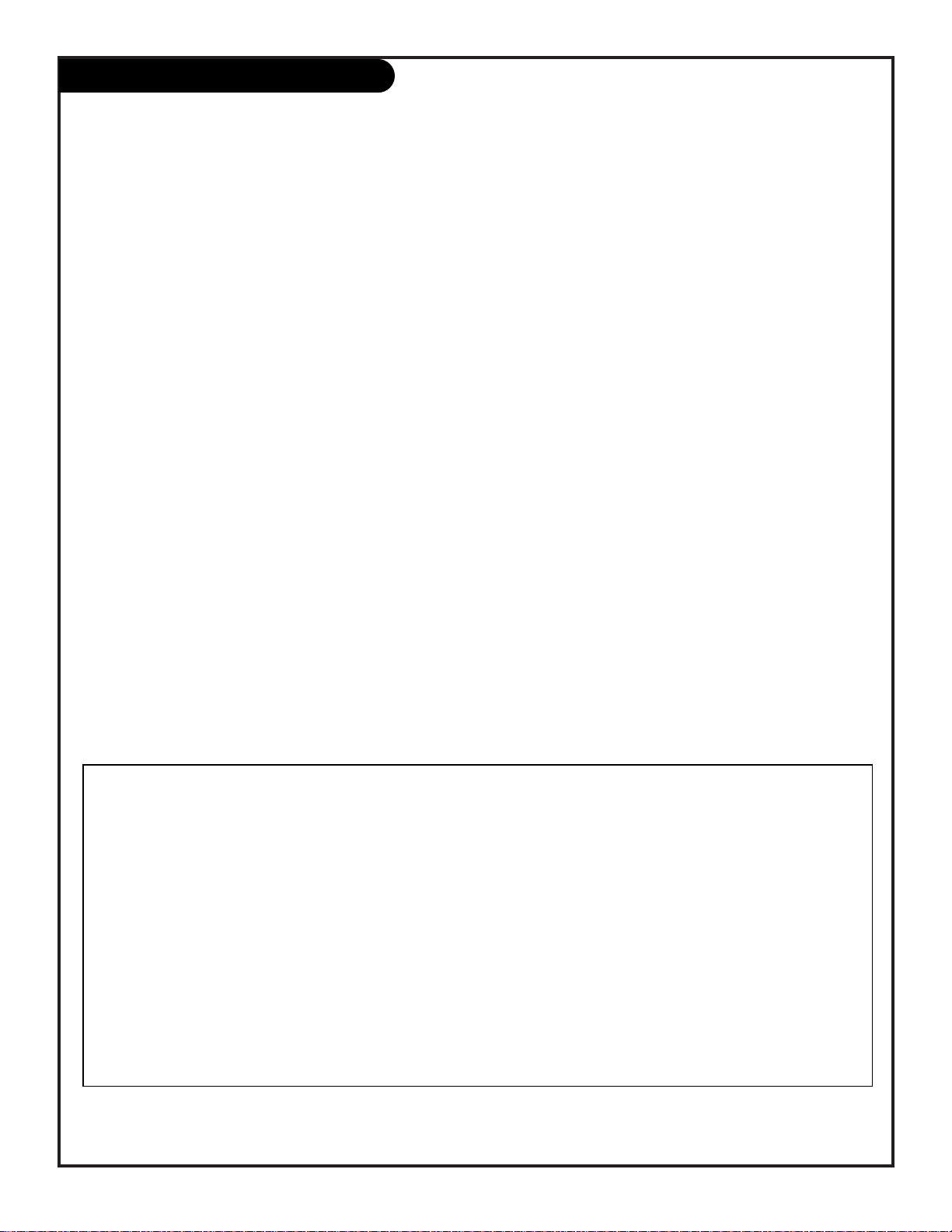
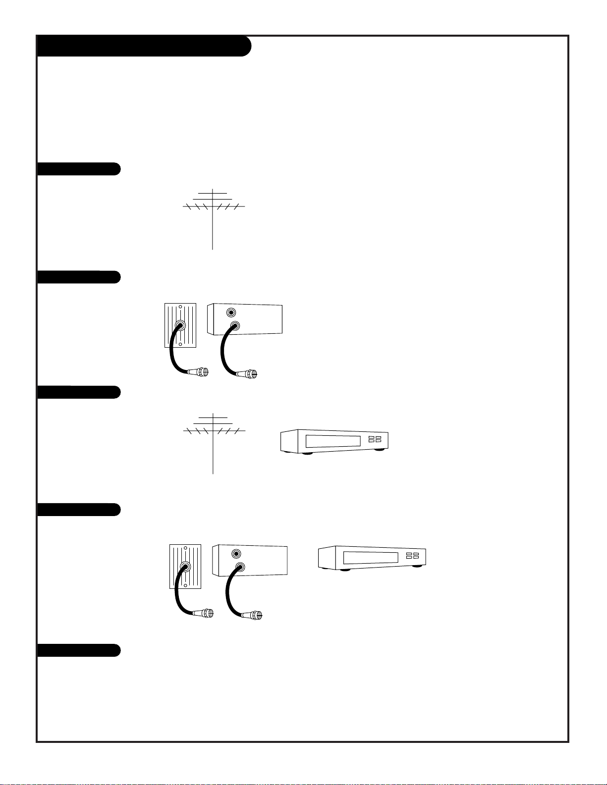
If you are using an antenna and no other equipment, go to . . . . . . . . . . . . . . . . . . page 7
If you subscribe to cable service and no other equipment, go to . . . . . . . . . . . . . . . page 8
If you are using an antenna and have a VCR, go to . . . . . . . . . . . . . . . . . . . . . . . page 9
If you subscribe to cable service and have a VCR, go to . . . . . . . . . . . . . . . . . . . . . page 10
This page directs you to the appropriate page for hook up your Entertainment Machine
IMPORTANT!!
Use this page to decide where you need to begin your setup. First, find the line below that best describes what you want
to do, then go to that page number.
Note: Design and specifications are subject to change without prior notification.
Cable TV
wall jack
Cable box
In
Out
Cable TV
wall jack
Cable box
In
Out
Antenna only
Cable only
Antenna with VCR
Cable and VCR
Other
If you have a Super VHS VCR, a DVD Player, or Audio equipment, go to . . . . . . . . . . . pages 11-12
Mini glossary
75 OHM RF CABLE The wire that comes from an off air antenna or cable service provider. Each end looks like a hex shaped nut with
a wire sticking through the middle, and it screws onto the threaded jack on the back of your TV.
300-75 OHM ADAPTER A small device that connects a two-wire 300 ohm antenna to a 75 ohm RF jack. They are usually about an
inch long with two screws on one end and a round opening with a wire sticking out on the other end.
Hook Up an Off Air Antenna
206-3375
PAGE 7
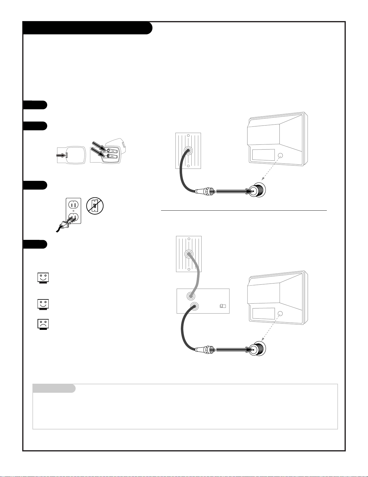
Connect an off air antenna to your Entertainment Machine
Hook up your Entertainment Machine,
see diagrams at right.
Remove the back of the remote and
put in two AAA batteries.
Plug in your TV. Do not plug it into a
switched outlet.
Go to page 13 to EZ Program your
Entertainment Machine.
RF coaxial wire
(75ohm)
Antenna
TV back
TV back panel
(expanded view)
Antenna
/ Cable
TV back
Flat wire
(300 ohm)
Antenna
300/75 ohm
Adapter
TV back panel
(expanded view)
Antenna
/ Cable
If you have a 75 ohm RF cable, then
you don’t need any adapters!
Remember, when screwing RF cables
onto jacks, clockwise tightens, and
counterclockwise loosens.
A 300 to 75 ohm adapter is not
included with your Zenith
Entertainment Machine.
back of
remote
120 V AC
60 Hz
1
2
3
4
Hook Up Cable Service (CATV)
206-3375
PAGE 8
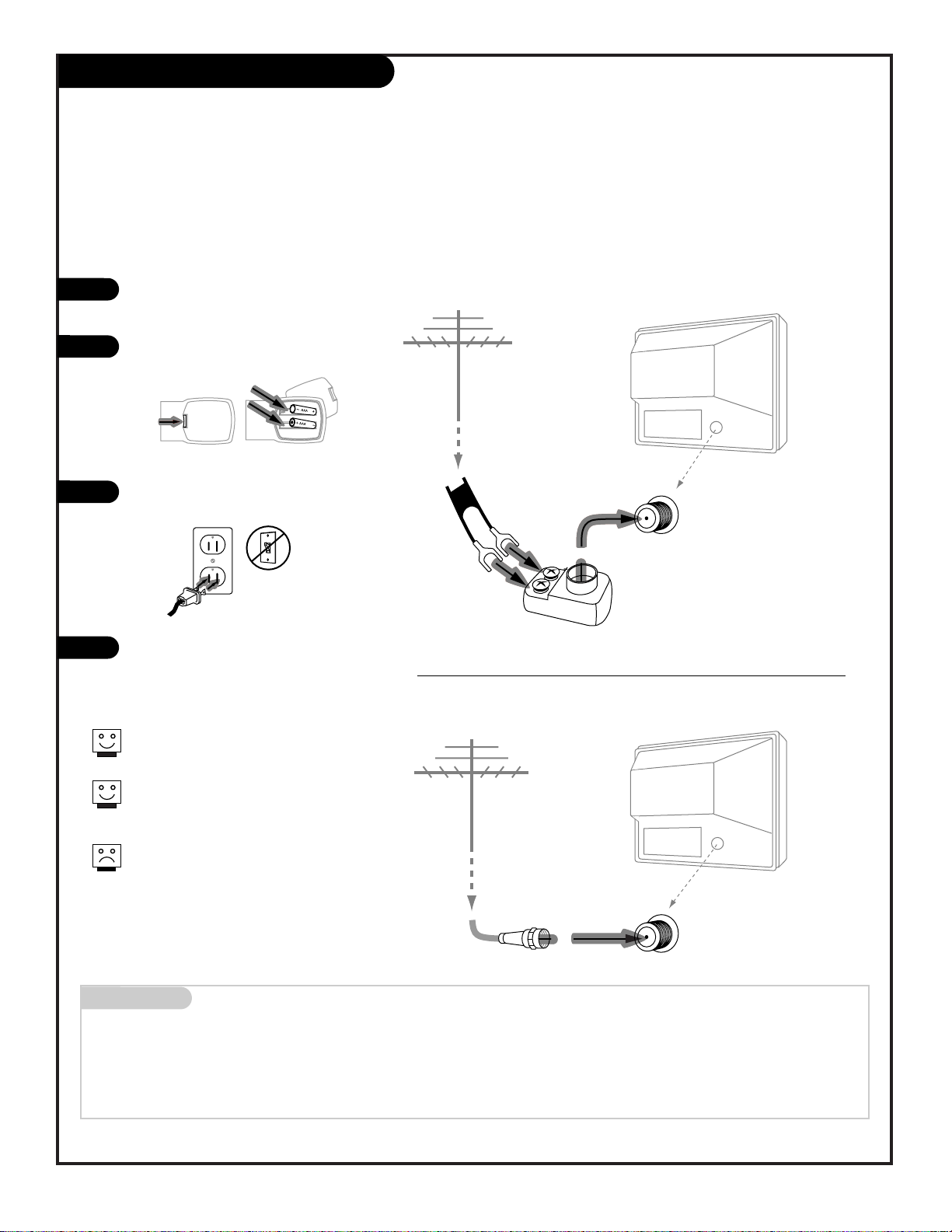
Connect Cable service to your Entertainment Machine
Hook up your Entertainment Machine,
see diagrams at right.
Remove the back of the remote and put
in two AAA batteries.
Plug in your TV. Do not plug it into a
switched outlet.
Go to page 13 to EZ Program your
Entertainment Machine.
Mini glossary
CABLE SERVICE The wire that supplies all your cable TV (CATV) stations.
Cable TV
wall jack
Cable TV
wall jack
Cable box
In
Out
RF coaxial wire (75ohm)
RF coaxial wire (75ohm)
3 4
output
switch
TV back panel
(expanded view)
Antenna
/ Cable
TV back
TV back panel
(expanded view)
Antenna
/ Cable
TV back
If you’re using a cable box, leave your
TV on channel 3 or 4 and use your
cable box to change channels.
Remember to set the cable box output
switch to channel 3 or 4.
If you’re using a cable box, EZ Program
(page 13) might only find the channel
your cable service is on
(usually channel 3 or 4). Don’t worry,
that’s all you need!
back of
remote
120 V AC
60 Hz
1
2
3
4
Without Cable Box
With Cable Box
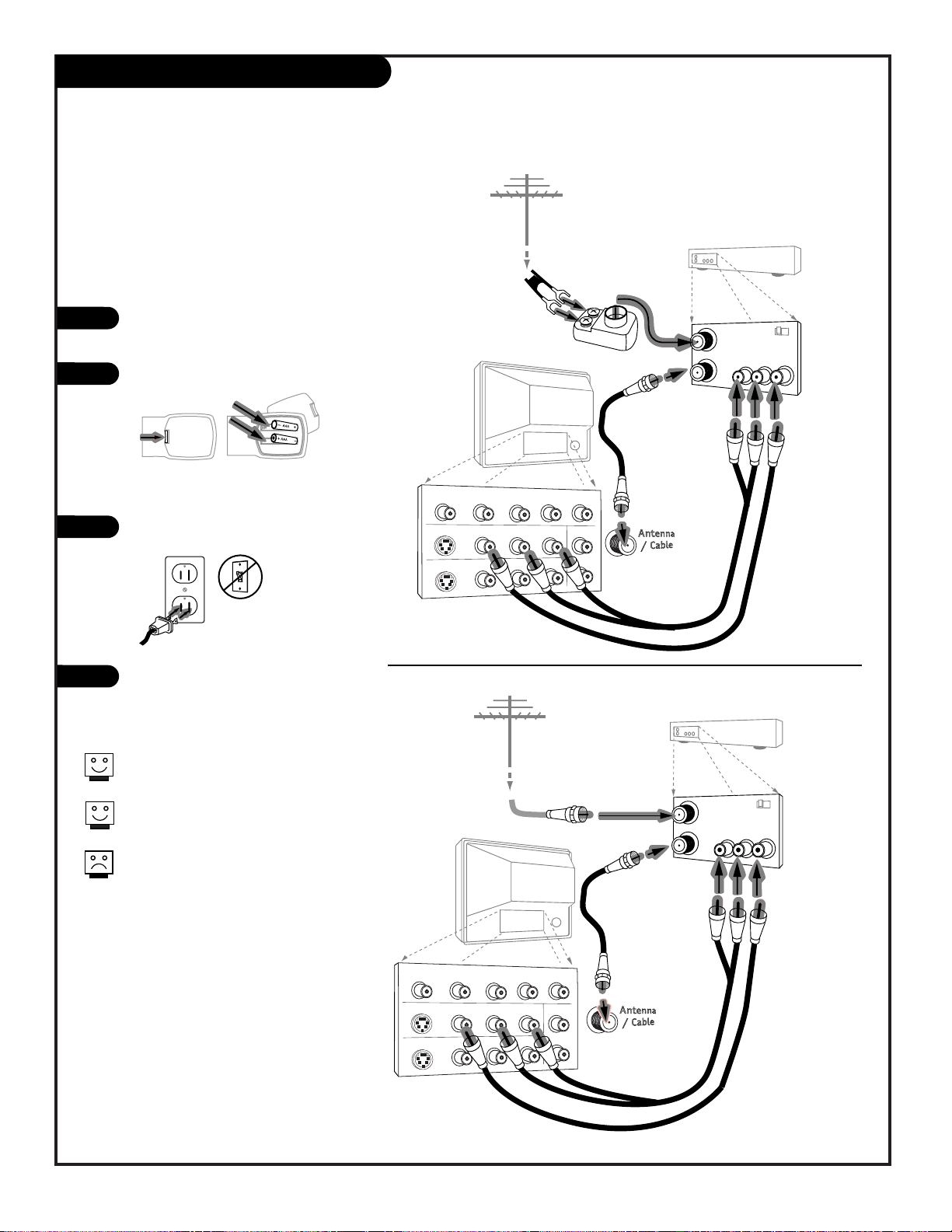
Hook up your Entertainment
Machine, see diagrams at right.
Remove the back of the remote
and put in two AAA batteries.
Plug in your TV. Do not plug it
into a switched outlet.
Go to page 13 to EZ Program your
Entertainment Machine.
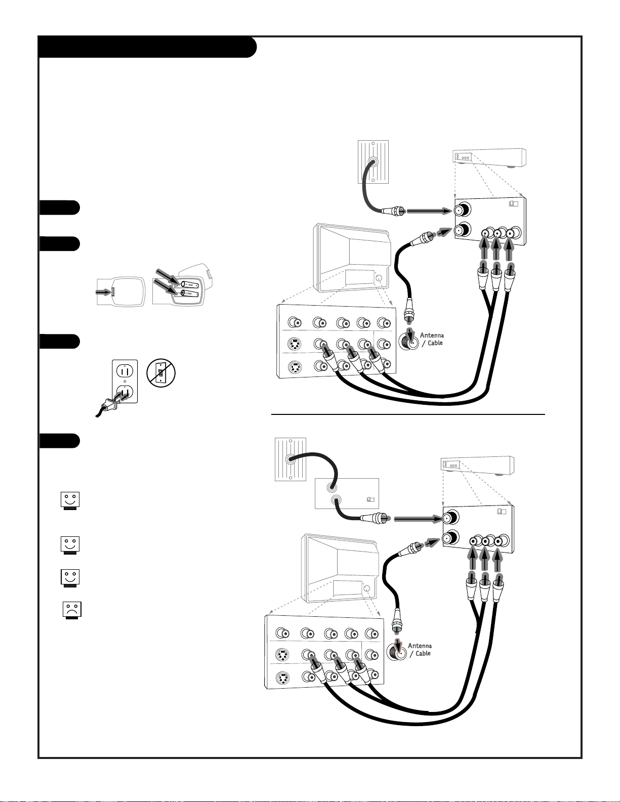
Hook Up Antenna and a VCR
206-3482
Connect your off air antenna and
VCR to your Entertainment Machine
COMPONENT VIDEO
Y
CR
CB
R
L
S-VIDEO 1
VIDEO 1
R-AUDIO
L-/MONO
VARIABLE
AUDIO OUTPUT
R
L
S-VIDEO 2
VIDEO 2
R-AUDIO
L-/MONO
TV back panel
(expanded view)
Typical
TV back
RF coaxial wire
(75ohm)
not included
with TV
In
Out
Audio
R-L Out
Video
Out
3 4
VCR back
VCR back A/V panel
In
Out
3 4
VCR back
VCR back A/V panel
Flat wire
(300 ohm)
Antenna
300/75 ohm
Adapter
Round wire (75ohm)
Antenna
output
switch
output
switch
A/V cables
not included
with TV
A/V cables
not included
with TV
TV back panel
(expanded view)
Typical
TV back
RF coaxial wire
(75ohm)
not included
with TV
Audio
R-L Out
Video
Out
COMPONENT VIDEO
Y
CR
CB
R
L
S-VIDEO 1
VIDEO 1
R-AUDIO
L-/MONO
VARIABLE
AUDIO OUTPUT
R
L
S-VIDEO 2
VIDEO 2
R-AUDIO
L-/MONO
back of
remote
120 V AC
60 Hz
Remember to set the VCR output
switch to channel 3 or 4.
Video sources provide better
picture and sound.
Without A/V cable hookup, VCRs
will not play videocassettes in
stereo sound.
1
2
3
4
(VCR with Round Antenna Wire)
(VCR with Flat Wire Antenna Adapter)
PAGE 9
Hook Up Cable (CATV) and a VCR
206-3482
PAGE 10
Connect Cable service and a
VCR to your Entertainment Machine
Leave your VCR and your television
tuned to channel 3 or 4 and use
the cable box to change channels.
Remember to set the cable box
output switch to channel 3 or 4.
Video sources provide better
picture and sound.
No A/V cables are included with
your Zenith Entertainment
Machine. Without A/V cable
hookups, VCRs will not play videocassettes in stereo sound.
TV back panel
(expanded view)
Typical
TV back
RF coaxial wire
(75ohm)
not included
with TV
In
Out
Audio
R-L Out
Video
Out
3 4
VCR back
VCR back A/V panel
In
Out
3 4
VCR back
VCR back A/V panel
output
switch
output
switch
A/V cables
not included
with TV
A/V cables
not included
with TV
TV back panel
(expanded view)
Typical
TV back
RF coaxial wire
(75ohm)
not included
with TV
Audio
R-L Out
Video
Out
Cable TV
wall jack
Cable box
In
Out
3 4
output
switch
Cable TV
wall jack
RF coaxial wire (75ohm)
COMPONENT VIDEO
Y
CR
CB
R
L
S-VIDEO 1
VIDEO 1
R-AUDIO
L-/MONO
VARIABLE
AUDIO OUTPUT
R
L
S-VIDEO 2
VIDEO 2
R-AUDIO
L-/MONO
COMPONENT VIDEO
Y
CR
CB
R
L
S-VIDEO 1
VIDEO 1
R-AUDIO
L-/MONO
VARIABLE
AUDIO OUTPUT
R
L
S-VIDEO 2
VIDEO 2
R-AUDIO
L-/MONO
back of
remote
120 V AC
60 Hz
Hook up your Entertainment
Machine, see diagrams at right.
Remove the back of the remote
and put in two AAA batteries.
Plug in your TV. Do not plug it
into a switched outlet.
Go to page 13 to EZ Program your
Entertainment Machine.
1
2
3
4
With Cable Box
Without Cable Box
COMPONENT VIDEO
Y
CR
CB
R
L
S-VIDEO 1
VIDEO 1
R-AUDIO
L-/MONO
VARIABLE
AUDIO OUTPUT
R
L
S-VIDEO 2
VIDEO 2
R-AUDIO
L-/MONO
Typical
TV back
Cables
not included
with TV
In
Out
3 4
Super VHS VCR
or DVD Player
Back A/V panel
Audio
R-L Out
S-Video
Out
(VCR Only)
Attach to
cable wall jack,
cable box, or
antenna
Mini glossary
SUPER S-VHS VCR Provides higher quality picture and sound than an ordinary VCR when connected to the S-Video in jacks.
DVD PLAYER Digital Video Disks use the S-Video in jacks (or if available on the DVD, Component Video jacks) to provide the
highest quality reproduction available from this technology.
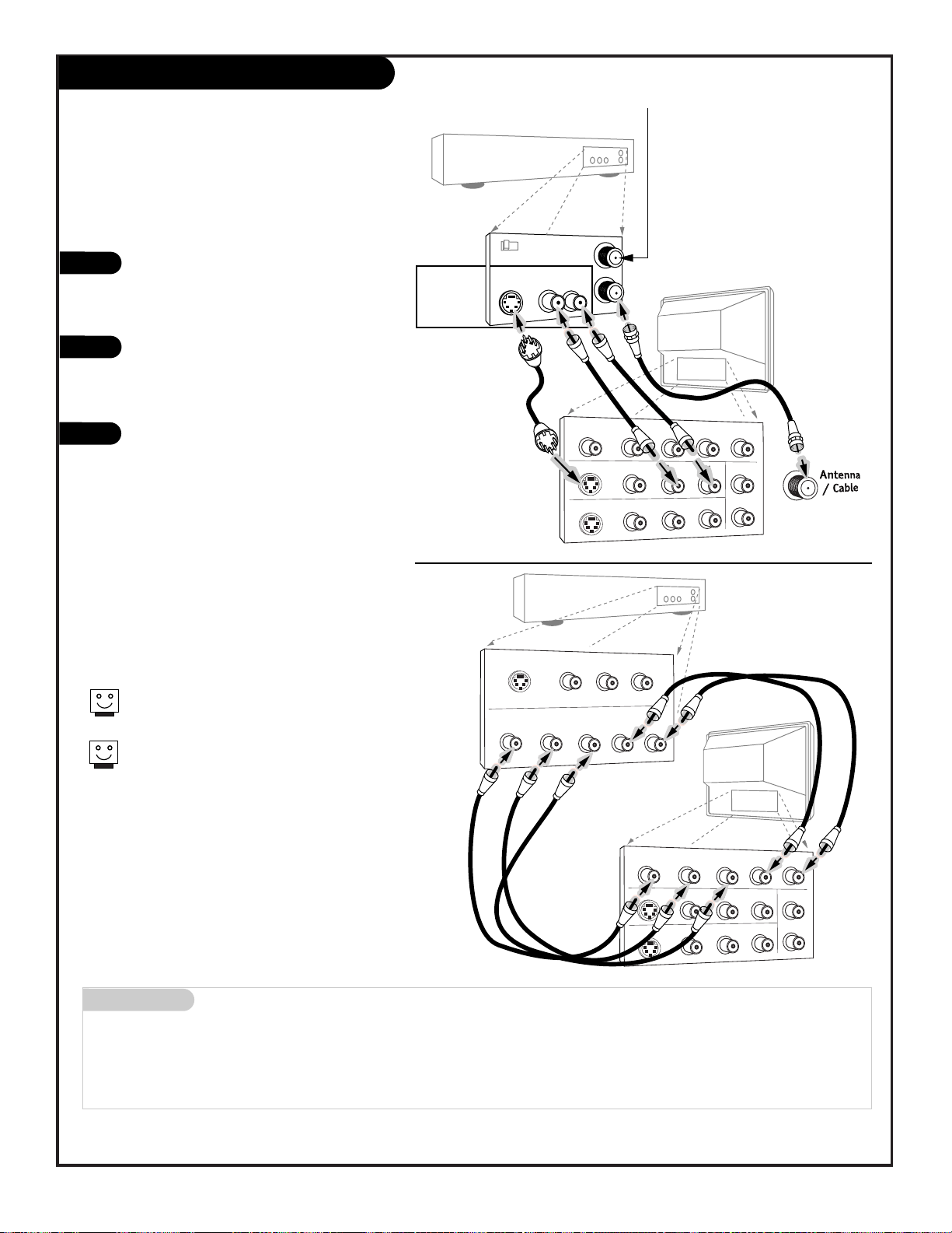
Connecting a S-VHS VCR or DVD player to
your Entertainment Machine
Super VHS VCR/DVD Player
Locate the Ant In jack on the back of your
S-VHS VCR. Connect the cable line coming
from your wall directly to
this jack.
Now locate the Out to TV jack. Connect a
cable from the Out to TV jack to the
Antenna/Cable jack on the back of
your TV.
Find the audio and S-Video jacks on the
back of your S-VHS VCR, and connect them
following the instructions provided with
your equipment.
1
2
3
Use Video/Audio sources for better
picture and sound.
To use with PIP: go to the Source Menu
(page 34) and choose the jack you’ve connected your S-VHS (S-VHS 1,-2) as the
Main or PIP source.
Super VHS VCR
DVD (Digital Video Disk) Player
Simply connect the S-Video/Audio out on the DVD
to the S-VIDEO 1, R-L AUDIO or S-VIDEO 2, R-L
AUDIO IN on the TV. For Component Video, connect the Component Video Out jacks on the DVD to
the COMPONENT VIDEO jacks on the TV.
DVD
Player
Jacks
PAGE 11
206-3482
DVD Player with
Component Video
S-VIDEO OUT
Y
VIDEO
COMPONENT VIDEO OUT
CR
R-AUDIO
L-/MONO
CB
L
R
CR
Y
S-VIDEO 1
S-VIDEO 2
Typical
TV back
COMPONENT VIDEO
CB
R
VIDEO 1
R-AUDIO
R-AUDIO
VIDEO 2
L-/MONO
L-/MONO
L
VARIABLE
AUDIO OUTPUT
R
L
206-3482
PAGE 12
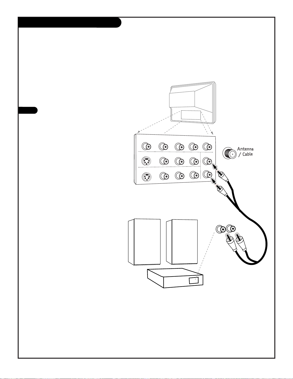
Audio Hookups
A/V cables
are not included
with TV
R-L Audio
Input
Stereo System
COMPONENT VIDEO
Y
CR
CB
R
L
S-VIDEO 1
VIDEO 1
R-AUDIO
L-/MONO
VARIABLE
AUDIO OUTPUT
R
L
S-VIDEO 2
VIDEO 2
R-AUDIO
L-/MONO
Typical
TV back
Locate the jacks marked R - L VARIABLE
AUDIO OUTPUT. These are for the stereo
system. Connect the stereo system’s cables,
according to their color (red is the right
channel, white the left) to these jacks.
1
Before you begin plugging in your stereo system, it’s a
good idea to put it in its approximate place first. That
way you know how much wire you have or will need.
Use your stereo to play the sound from your Entertainment Machine
Mini glossary
OFF AIR ANTENNA The device receiving the program signal broadcast over-the-air.
CABLE Your EZ Program selection, if you subscribe to a cable service.
EZ Program (Channel Search)
1
2
3
4
5
6
Use EZ Program to automatically find and store in the
TV’s memory all the channels in your area.
Select:
Antenna If you receive off air signal reception.
Cable If you subscribe to a cable service.
prg
cable
vcr
aux
tv
123
456
7089
menu
pip
pip ch
freez
surf
mute
power
volume volume
tv/vcr
source
flashbk
enter
timer
pause
record
play
stop
rewind f. fwd
quit
channel
channel
V-CHIP+
Setup Menu
EZ Program
Add/Del/Surf
Clock Set
Captions
Caption/Text
Language
To Program
123
7
3/5
1
206-3482
Note: EZ Program finds channels being received by the TV
tuner. See page 17 for instructions on using the Cable Box or
VCR tuners.
Cable will not work unless you subscribe to a cable service.
PAGE 13
With the remote control in hand, press POWER to turn
on your Entertainment Machine.
Press MENU repeatedly until the Setup menu appears.
Using the UP or DOWN arrow on the remote control,
select EZ Program on your screen.
Press the RIGHT or LEFT arrow to show the EZ
Program menu.
Using the UP or DOWN arrow, choose either Off Air
Antenna, or Cable on your screen.
Note: The option that is blinking is selected.
Press the RIGHT or LEFT arrow to begin the channel
search.
When the search is complete, press QUIT to return to
TV viewing.
7
2
4/6
206-3482
PAGE 14
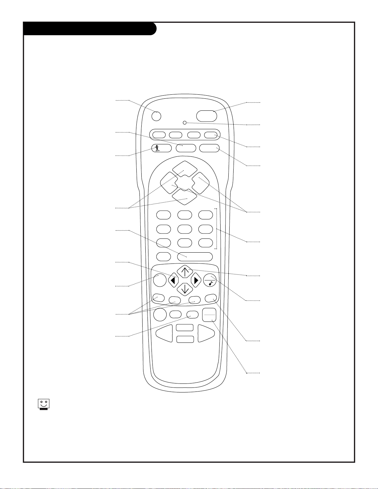
Remote Key Functions in TV Mode
Note: Pressing TV puts remote into TV operating mode
A quick list of the keys on your remote and what they do in TV mode, see page 49 for remote key
functions in the other modes
prg
cable
vcr
aux
tv
123
456
7
0
89
menu
pip
pip ch
freez
surf
mute
power
volume volume
tv/vcr
source
flashbk
enter
timer
pause
record
play
stop
rewind f. fwd
quit
channel
channel
V-CHIP+
PRG (PROGRAM)
Programs your remote to operate
other products.
See page 43.
FLASHBK (FLASHBACK)
Return to the last channel viewed.
Selects AM/PM in Clock/Timer menus.
POWER
Turns TV On or Off
.
CABLE/VCR/AUX/TV
Selects remote operating mode.
CHANNEL (UP/DOWN)
Flip through available channels.
MUTE
Turns sound Off and On
while the picture remains.
Press once to quiet sound, press
again to mute, press again to
restore sound.
ENTER
Shows the Channel/Time
display. Press after channel num-
bers for instant selection.
NUMBER KEYPAD
Selects channels directly and
enters numeric values for
some options
.
MENU
Shows on-screen
menus for TV mode. See page 18.
UP/DOWN ARROWS
The Up/Down arrows select menu
options.
remote control part number
MBR3464Z
(124-233-02)
TIMER
Displays the Sleep Timer Menu. See
“Timer Setup” on page 24 for more
information.
VOLUME LEFT/RIGHT
Adjusts the sound level on your
Entertainment Machine.
QUIT
Removes on-screen display from
view. If no display is on, switches
Surround sound feature On and Off on
some TVs.
TV/VCR SOURCE
Switches between watching TV
through your antenna/cable, or
through your VCR.
Keys dedicated to VCR functions
will still operate your VCR while
the remote is in TV mode.
V-CHIP Plus+
Kid’s TV, Blocks or sets up to Watch
programs using VCR+ PlusCodes.
See pages 35, 36, 37, 38, 39.
LEFT/RIGHT ARROWS
The Left/Right arrows adjust
menu options.
LED INDICATOR LIGHT
Lights when keys are pressed.
PIP FEATURES
For PIP (Picture-in-Picture)
operation. See page 40.
SURF
Turns on and off custom channel
selection mode.
When Surf mode is active, CHANNEL
Up/Down keys “Surf” through the
channels you’ve selected.
Mini glossary
MENU On-screen displays you use to program the TV features.
SELECT Pressing the UP or DOWN arrow repeatedly will “select” or highlight menu options.
ADJUST Use the LEFT or RIGHT arrow to choose or change the selected menu option.
QUIT When finished with programming, press QUIT to exit on-screen menus and return to TV viewing.
5
prg
cable
vcr
aux
tv
123
456
7089
menu
pip
pip ch
freez
surf
mute
power
volume volume
tv/vcr
source
flashbk
enter
timer
pause
record
play
stop
rewind f. fwd
quit
channel
channel
V-CHIP+
206-3482
PAGE 15
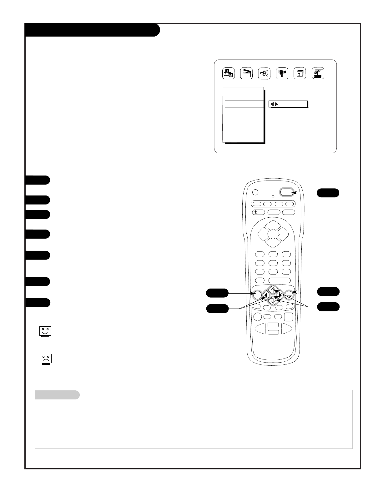
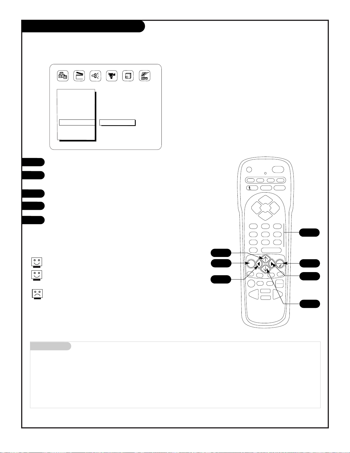
On-Screen Menu Operation
1
2
3
4
5
Use either the remote control or the TV front controls to access the on-screen menus
Setup Menu
EZ Program
Add/Del/Surf
Clock Set
Captions
Caption/Text
Language
EZ Mute
123
On-screen menus automatically disappear after 15 seconds.
Use the NUMBER keypad to enter numerical values for menu adjustments
when required.
Remote must be in the TV mode for it to control the TV.
Press TV on the remote to select TV mode.
Press MENU repeatedly until the desired menu appears.
Use the UP or DOWN arrow on the remote control, to “select”
an option like Captions on your screen.
Use the RIGHT or LEFT arrow to “adjust” the selected option.
Press QUIT when finished, to return to TV viewing.
In the Clock, and Timer menus, use the NUMBER keypad to set
the clock, and timer features.
4
1
2
3
2
3
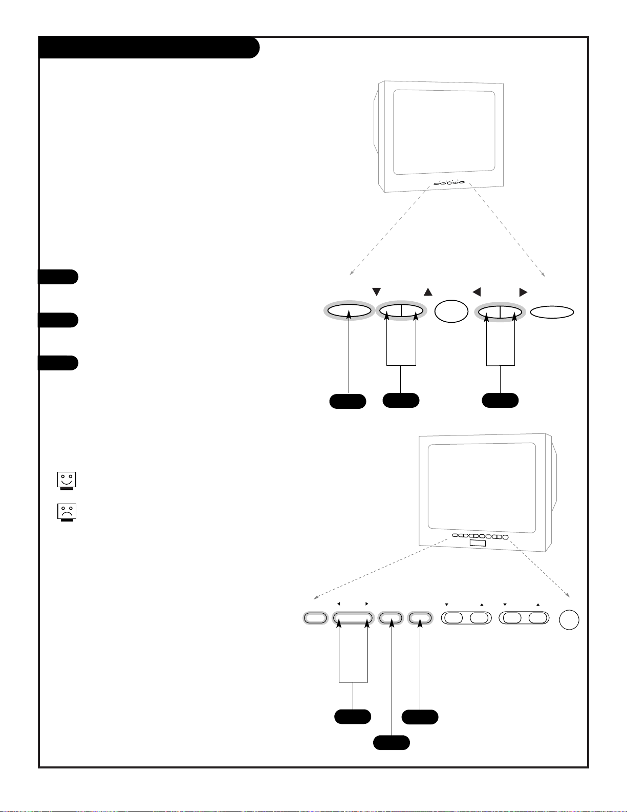
Front Panel Controls
206-3482
PAGE 16
How to use your front control panel to operate
the menus
menu
channel
volume
power
menu
channel
volume
power
To access the on-screen menus, press MENU.
Pressing MENU repeatedly will cycle through
the available menus.
Once the menu you want appears,
SELECT the feature you want to change using
the DOWN or UP arrow Channel buttons.
ADJUST or change the selected feature using
the LEFT or RIGHT Volume buttons.
Note: If the feature you want to change
requires you to enter numerical values, use
the remote control.
Menus disappear after fifteen seconds. To get them
back, press MENU again.
If you’ve lost your remote, you can get a new one
by calling 1-800-255-6790 to purchase a replacement.
1
2
3
When using the on-screen menus, the buttons on the
6-Button front panel correspond to the remote control
keys as follows:
CHANNEL = Select Up/Down
VOLUME = Adjust Left/Right
1
32
Typical 6-Button Panel
1
3
2
Typical 10-Button Panel
enter adjust select menu volume channel power
Basic TV Operation Tuners/Sources
206-3482
PAGE 17
Basic operating information and using your Entertainment Machine with other equipment
There are a number of ways you can choose to integrate your Entertainment Machine with the rest of your audio/video
equipment. Channels can be changed using the television, the VCR, or the cable box, with advantages to each.
USING THE TELEVISION AS THE TUNER preserves all your channel labels (not available on some models). It also
reduces the number of keys on the remote control you need to worry about. (One device, one remote to learn.)
USING THE VCR AS THE TUNER has the advantage of simplifying the recording process. If the VCR is tuned to channel seven, then the VCR will record channel seven.
USING THE CABLE BOX (if you have one) to change the stations sometimes has an advantage, too, especially if your
cable provider requires you to use their cable box to descramble their stations.
Tuner
Source
The source button (TV/VCR/Source) on the remote switches between Video input and Antenna/Cable input. The
Channel/Time display will read “Video” in place of a channel number if A/V inputs are selected as the picture source.
Antenna/Cable Input: This setting allows you to change cable or antenna channels and to view videocassettes on channel 3 (or 4) in mono sound.
Video Input: This setting allows stereo playback of videocassettes. The television cannot change channels in the Video
mode, but the VCR can.
Mini glossary
TUNER The television, VCR, or cable box that you choose to change channels with.
SOURCE Connection on the TV’s back jack connection panel providing picture and sound to the TV.
To view the current input source, press ENTER on your remote. The Channel/Time display should appear in the upper right-hand
corner of the screen. If the display reads ‘Video,’ then the picture and sound source is connected to one set of the Audio/Video
input jacks. If the display reads a channel number, then the picture and sound source is the Antenna/Cable jack.
Turn on the TV and other equipment.
Select your picture and sound source. See information on tuners and picture sources below.
Adjust controls for picture (Video) and sound (Audio). See short descriptions of the on-screen menus/displays
beginning on page 18 and 19; use these to personalize the features of your Entertainment Machine.
1
2
3
 Loading...