

Page 1
SERVICE MANUAL
Model Series:
Product Type: Color TV
Chassis: MX474C
Manual Series: CM153
Manual Part #: 923-03459
Model Line: D
Product Year: 2001
General Information ....................................... 1
Servicing ..................................................... 2
Parts ........................................................... 3
Exploded views ............................................. 4
Schematics ................................................... 5
H13A02D
H13A02X
CONTENTS
Printed in U.S.A.
CN DG 5k
Published by Technical Publications
Zenith Electronics Corporation
201 James Record Road - Huntsville, Alabama 35824-1513
Copyright October 2001 by Zenith Electronics Corporation
Page 2

PRODUCT SAFETY SERVICING GUIDELINES FOR AUDIO-VIDEO PRODUCTS
A
IMPORTANT SAFETY NOTICE
This manual was prepared for use only by properly trained audio-visual service
technicians.
When servicing this product, under no circumstances should the original
design be modified or altered without permission from Zenith Electronics
Corporation. All components should be replaced only with types identical to
those in the original circuit and their physical location, wiring and lead dress
must conform to original layout upon completion of repairs.
Special components are also used to prevent x-radiation, shock and fire hazard.
These components are indicated by the letter “x” included in their component
designators and are required to maintain safe performance. No deviations are
allowed without prior approval by Zenith Electronics Corporation.
Circuit diagrams may occasionally differ from the actual circuit used. This way,
implementation of the latest safety and performance improvement changes into
the set is not delayed until the new service literature is printed.
Caution: Do not attempt to modify this product in any way. Never perform
customized installations without manufacturer’s approval. Unauthorized
modifications will not only void the warranty, but may lead to property damage
or user injury.
Service work should be performed only after you are thoroughly familiar with
these safety checks and servicing guidelines.
Graphic symbols
The exclamation point within an equilateral triangle is intended
to alert the service personnel to important safety information in
the service literature.
The lightning flash with arrowhead symbol within an equilateral
triangle is intended to alert the service personnel to the presence
of noninsulated “dangerous voltage” that may be of sufficient
magnitude to constitute a risk of electric shock.
The pictorial representation of a fuse and its rating within an
equilateral triangle is intended to convey to the service personnel
the following fuse replacement caution notice:
CAUTION: FOR CONTINUED PROTECTION AGAINST RISK OF FIRE,
REPLACE ALL FUSES WITH THE SAME TYPE AND RATING AS MARKED
NEAR EACH FUSE.
SERVICE INFORMATION
While servicing, use an isolation transformer for protection from AC line shock.
After the original service problem has been corrected, make a check of the
following:
FIRE AND SHOCK HAZARD
1. Be sure that all components are positioned to avoid a possibility of
adjacent component shorts. This is especially important on items transported to and from the repair shop.
2. Verify that all protective devices such as insulators, barriers, covers,
shields, strain reliefs, power supply cords, and other hardware have been
reinstalled per the original design. Be sure that the safety purpose of the
polarized line plug has not been defeated.
3. Soldering must be inspected to discover possible cold solder joints, solder
splashes, or sharp solder points. Be certain to remove all loose foreign
particles.
4. Check for physical evidence of damage or deterioration to parts and components, for frayed leads or damaged insulation (including the AC cord), and
replace if necessary.
5. No lead or component should touch a receiving tube or a resistor rated at
1 watt or more. Lead tension around protruding metal surfaces must be
avoided.
6. After re-assembly of the set, always perform an AC leakage test on all exposed
metallic parts of the cabinet (the channel selector knobs, antenna terminals,
handle and screws) to be sure that set is safe to operate without danger of
electrical shock. DO NOT USE A LINE ISOLATION TRANSFORMER DURING THIS
TEST. Use an AC voltmeter having 5000 ohms per volt or more sensitivity in
the following manner: Connect a 1500 ohm, 10 watt resistor, paralleled by
a .15 mfd 150V AC type capacitor between a known good earth ground
water pipe, conduit, etc.) and the exposed metallic parts, one at a time.
Measure the AC voltage across the combination of 1500 ohm resistor and
.15 mfd capacitor. Reverse the AC plug by using a non-polarized adaptor
and repeat AC voltage measurements for each exposed metallic part. Voltage
measured must not exceed 0.75 volts RMS. This corresponds to 0.5 milliamp
AC. Any value exceeding this limit constitutes a potential shock hazard and
must be corrected immediately.
.C. Voltmeter
Good Earth Ground
such as the Water
Pipe, Conduit, etc.
0.16uF
1600 OHM
10 WATT
Place this probe
on each exposed
metal part.
X-RADIATION
1. Be sure procedures and instructions to all service personnel cover the
subject of x-radiation. The only potential source of x-rays in current TV
receivers is the picture tube. However, this tube does not emit x-rays when
the HV is at the factory-specified level. The proper value is given in the
applicable schematic. Operation at higher voltages may cause a failure of
the picture tube or high-voltage supply and, under certain circumstances
may produce radiation in excess of desirable levels.
2. Only factory-specified CRT anode connectors must be used.
3. It is essential that the service personnel have available an accurate and
reliable high-voltage meter.
4. When the high-voltage circuitry is operating properly, there is no possibility
of an x-radiation problem. Every time a color chassis is serviced, the
brightness should be run up and down while monitoring the high voltage
with a meter, to be certain that the high voltage does not exceed the
specified value and that it is regulating correctly.
5. When troubleshooting and making test measurements in a product with a
problem of excessively high voltage, avoid being unnecessarily close to
the picture tube and the high voltage power supply. Do not operate the
product longer than necessary to locate the cause of excessive voltage.
6. Refer to HV, B+, and shutdown adjustment procedures described in the
appropriate schematics and diagrams (where used).
IMPLOSION
1. All direct view picture tubes are equipped with an integral implosion
protection system; take care to avoid damage during installation.
2. Use only the recommended factory replacement tubes.
TIPS ON PROPER INSTALLATION
1. Never install any receiver in a closed-in recess, cubbyhole, or closely
fitting shelf space over, or close to, a heat duct, or in the path of heated
air flow.
2. Avoid conditions of high humidity such as: outdoor patio installations
where dew is a factor, near steam radiators where steam leakage is a factor,
etc.
3. Avoid placement where draperies may obstruct venting. The customer
should also avoid the use of decorative scarves or other coverings that
might obstruct ventilation.
4. Wall- and shelf-mounted installations using a commercial mounting kit
must follow the factory-approved mounting instructions. A product mounted
to a shelf or platform must retain its original feet (or the equivalent
thickness in spacers) to provide adequate air flow across the bottom. Bolts
or screws used for fasteners must not touch any parts or wiring. Perform
leakage tests on customized installations.
5. Caution customers against mounting a product on a sloping shelf or in a
tilted position, unless the receiver is properly secured.
6. A product on a roll-about cart should be stable in its mounting to the cart.
Caution the customer on the hazards of trying to roll a cart with small
casters across thresholds or deep pile carpets.
7. Caution customers against using a cart or stand that has not been listed
by Underwriters Laboratories, Inc. for use with its specific model of
television receiver or generically approved for use with TVs of the same or
larger screen size.
8. Caution customers against using extension cords. Explain that a forest of
extensions, sprouting from a single outlet, can lead to disastrous
consequences to home and family.
i
Page 3

TABLE OF CONTENTS
SECTION 1 GENERAL INFO / REMOTE CONTROL
SPECIFICATIONS .......................................................... 1-1
SECTION 2 SERVICING
DISASSEMBLY INSTRUCTION .......................................... 2-1
SERVICE MODE LIST ..................................................... 2-3
ALIGNMENT INSTRUCTION ............................................. 2-4
ELECTRICAL ADJUSTMENT ............................................. 2-4
MAJOR COMPONENTS LOCATION GUIDE ........................... 2-7
SECTION 3 EXPLODED VIEW
EXPLODED VIEW .......................................................... 3-1
SECTION 4 PARTS LIST
COMPONENT PARTS LIST ............................................... 4-1
SECTION 5 SCHEMATIC
H13A02D/02X POWER SUPPLY CIRCUIT ........................... 5-1
H13A02D/02X DEFLECTION CIRCUIT ............................... 5-2
H13A02D/02X MAIN MICRO & TUNER CIRCUIT .................. 5-3
H13A02D/02X CHROMA CIRCUIT .................................... 5-4
H13A02D/02X AUDIO CIRCUIT ....................................... 5-5
H13A02D/02X PCB LAYOUT TOP ..................................... 5-6
H13A02D/02X PCB LAYOUT BOTTOM ............................... 5-7
CM153 TOC MX474C - TOC
Page 4

Page 5
SPECIFICATIONS
MODEL
ITEMS
TV STANDARD NTSC-M
POWER INPUT AC 120V 60 Hz
POWER CONSUMPTION
TUNING SYSTEM Frequency Synthesizer ( FS ) Tuning System
TUNING RANGES
SOUND OUTPUT
SPEAKER
ANTENNA INPUT IMPEDANCE 75 ohm Unbalanced
AUXILIARY
INPUT TERMINAL
INTERMEDIATE
FREQUENCIES
Picture IF Carrier Frequency : 45.75 MHz
H13A02D / H13A02X
54W
VHF : 2 ~ 13 (12)
~
~
1.0 W
Front :
Rear:
69 (56)
181 (181)
UHF : 14
CATV : 1
1 W 8 ohm
Ear Phone Jack
VHF/UHF Antenna Input
Sound IF Carrier Frequency : 41.25 MHz
REMARKS
REMARKS
CM153 1-1 MX474C - GENERAL INFO
Page 6

Page 7

SERVICE MODE LIST
This unit provided with the following SERVICE MODES so you can repair, examine and adjust easily.
To enter the Service Mode, press both set key and remote control key for more than 1 second.
Set Key Remocon Key Operations
VOL. (-) MIN
VOL. (-) MIN 1
VOL. (-) MIN
VOL. (-) MIN 8
VOL. (-) MIN 9
0
6
Releasing of V-CHIP PASSWORD.
Initialization of the factory.
NOTE: Do not use this for the normal servicing.
POWER ON total hours is displayed on the screen.
Refer to the "CONFIRMATION OF USING HOURS".
Can be checked of the INITIAL DATA of MEMORY IC.
Refer to the "NOTE FOR THE REPLACING OF MEMORY IC".
Writing of EEPROM initial data.
NOTE: Do not use this for the normal servicing.
Display of the Adjustment MENU on the screen.
Refer to the "ELECTRICAL ADJUSTMENT" (On-Screen Display Adjustment).
CONFIRMATION OF USING HOURS
POWER ON total hours can be checked on the screen. Total hours are displayed in 16 system of notation.
1.
Set the VOLUME to minimum.
2.
Press both VOL. DOWN button on the set and Channel
button (6) on the remote control for more than 1 second.
3.
After the confirmation of using hours, turn off the power.
ADDRESS DATA
INIT 00 83
CRT ON
0010
FIG. 1
Initial setting content of MEMORY IC.
POWER ON total hours.
= (16 x 16 x 16 x thousands digit value)
+ (16 x 16 x hundreds digit value)
+ (16 x tens digit value)
+ (ones digit value)
NOTE FOR THE REPLACING OF MEMORY IC
If a service repair is undertaken where it has been required to change the MEMORY IC, the following steps should be taken to
ensure correct data settings while making reference to TABLE 1.
Table 1
09
INI
0A
FF
ADDRESS
DATA
1.
Enter DATA SET mode by setting VOLUME to minimum.
2.
Press both VOL. DOWN button on the set and Channel button (6) on the remote control for more than 1 second.
ADDRESS and DATA should appear as FIG 1.
3.
ADDRESS is now selected and should "blink". Using the SET + or - keys on the remote, step through the ADDRESS until
required ADDRESS to be changed is reached.
4.
Press ENTER to select DATA. When DATA is selected, it will "blink".
5.
Again, step through the DATA using SET + or - until required DATA value has been selected.
6.
Pressing ENTER will take you back to ADDRESS for further selection if necessary.
7.
Repeat steps 3 to 6 until all data has been checked.
8.
When satisfied correct DATA has been entered, turn POWER off (return to STANDBY MODE) to finish DATA input.
The unit will now have the correct DATA for the new MEMORY IC.
CM153 2-1 MX474C - SERVICING
INI00INI01INI02INI03INI04INI05INI06INI07INI08INI
0809A00106B324992125
Page 8
ALIGNMENT INSTRUCTIONS
1. SERVICE MODE ADJUSTMENS
Follow the steps below whenever service adjustment is required. See Table- A and Table- B to determine if
service adjustments are required.
NOTE
\
To perform the service mode for model H13A02D/02X, please perform the following steps on part OS101.
1) Remote control PN# 924-10053 is needed to complete the following.
2) Remove 3pin terminal at location OS101 and add IR sensor PN# 942-10065.
3) Enter the Service mode and adjust.
4) Remove IR pre Amp after all menu adjustments have been completed.
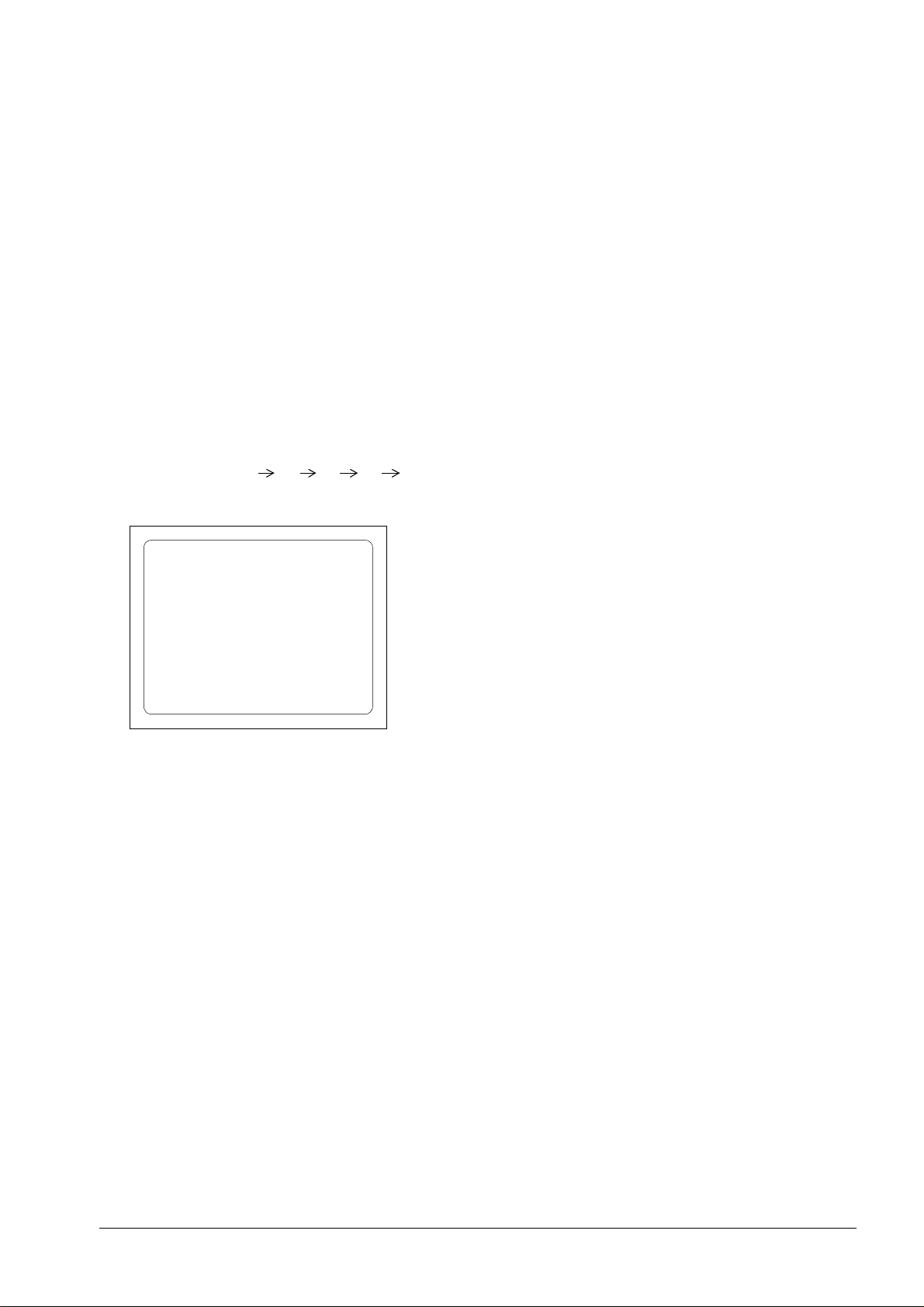
1) How to enter the service mode using your remote control.
•
Turn the set on.
•
Direct the remote control to the reception window of TV.
•
Push buttons of remote control in sequence as follows.
Menu (5 sec.)
•
Then, the screen will appear as follows.
9
8
7
6
S2 SCRN
S5 IFC
S6 GEO
S8 W/B
S9 DP
S12 FACT
S10 SOUND
REM Zenith
NOTE
If you changed the setting of “REM Zenith” item, then your remote control will not work. In that case, unplug your
power cord and plug it again.
•
Using the channel up or channel down button, select the item you wish to adjust.
(The color of selected item turns
•
Press the volume up or down button to enter in the service mode you wish to adjust.
red.)
CM153 2-2 MX474C - SERVICING
Page 9
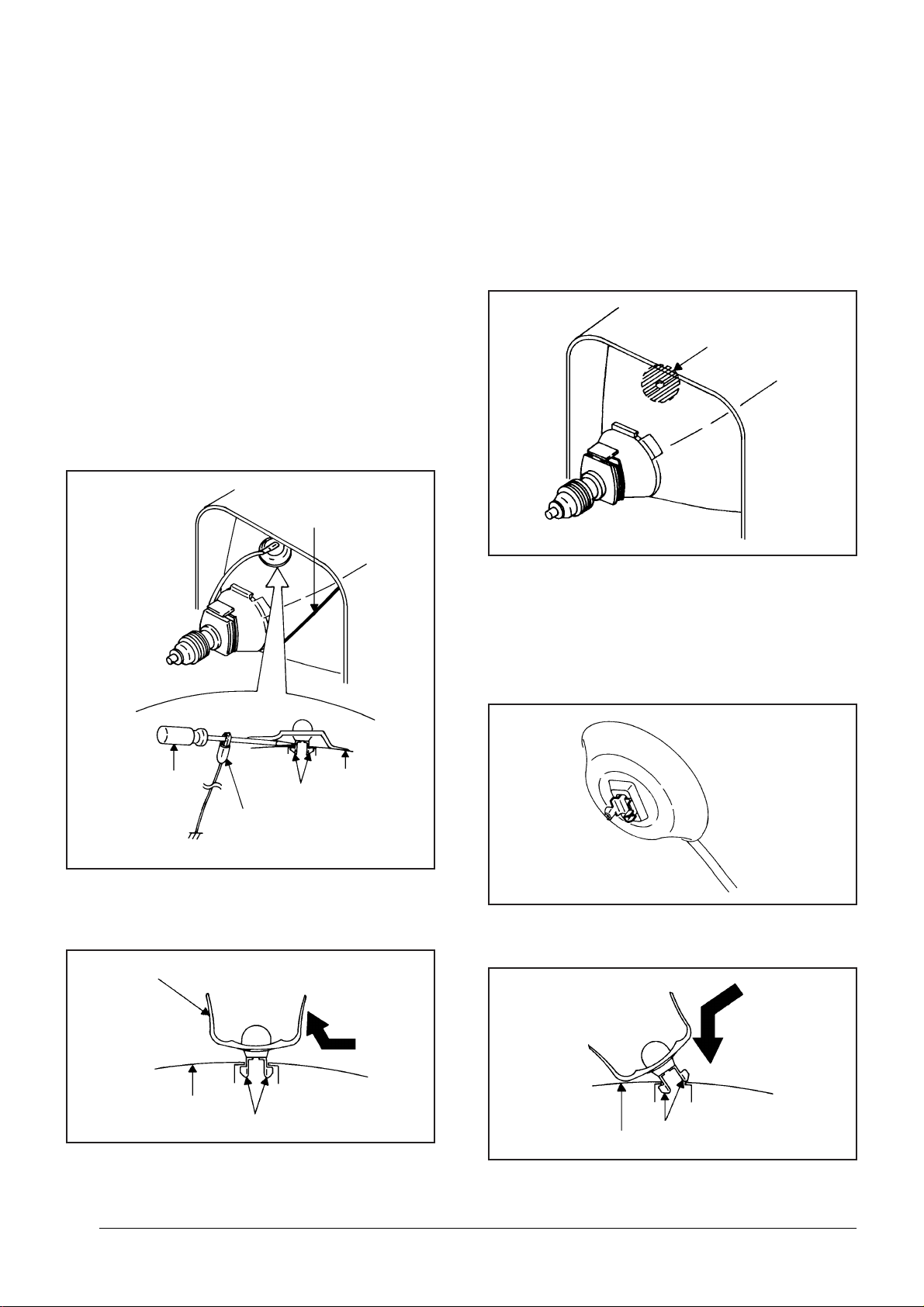
DISASSEMBLY INSTRUCTIONS
1. REMOVAL OF ANODE CAP
Read the following NOTED items before starting work.
*
After turning the power off there might still be a potential
voltage that is very dangerous. When removing the
Anode Cap, make sure to discharge the Anode Cap's
potential voltage.
*
Do not use pliers to loosen or tighten the Anode Cap
terminal, this may cause the spring to be damaged.
REMOVAL
1. Follow the steps as follows to discharge the Anode Cap.
(Refer to Fig. 1-1.)
Connect one end of an Alligator Clip to the metal part of a
flat-blade screwdriver and the other end to ground.
While holding the plastic part of the insulated Screwdriver,
touch the support of the Anode with the tip of the
Screwdriver.
A cracking noise will be heard as the voltage is discharged.
GND on the CRT
3. After one side is removed, pull in the opposite direction to
remove the other.
NOTE
Take care not to damage the Rubber Cap.
INSTALLATION
1. Clean the spot where the cap was located with a small
amount of alcohol. (Refer to Fig. 1-3.)
Location of Anode Cap
Fig. 1-3
NOTE
Confirm that there is no dirt, dust, etc. at the spot where
the cap was located.
2.3.Arrange the wire of the Anode Cap and make sure the
wire is not twisted.
Turn over the Rubber Cap. (Refer to Fig. 1-4.)
Screwdriver
Alligator Clip
GND on the CRT
Flip up the sides of the Rubber Cap in the direction of the
2.
arrow and remove one side of the support.
(Refer to Fig. 1-2.)
Rubber Cap
CRT
Support
Support
CRT
Fig. 1-1
Fig. 1-2
Fig. 1-4
4. Insert one end of the Anode Support into the anode button,
then the other as shown in Fig. 1-5.
Support
CRT
5.6.Confirm that the Support is securely connected.
Put on the Rubber Cap without moving any parts.
Fig. 1-5
CM153 2-3 MX474C - SERVICING
Page 10

ELECTRICAL ADJUSTMENTS
1. BEFORE MAKING ELECTRICAL
ADJUSTMENTS
Read and perform these adjustments when repairing the
circuits or replacing electrical parts or PCB assemblies.
CAUTION
•
Use an isolation transformer when performing any
service on this chassis.
•
Before removing the anode cap, discharge electricity
because it contains high voltage.
•
When removing a PCB or related component, after
unfastening or changing a wire, be sure to put the wire
back in its original position.
Inferior silicon grease can damage IC's and transistors.
•
When replacing IC's and transistors, use only specified
silicon grease (YG6260M).
Remove all old silicon before applying new silicon.
Prepare the following measurement tools for electrical
adjustments.
1. Synchro Scope
2. Digital Voltmeter
On-Screen Display Adjustment
1. In the condition of NO indication on the screen.
Press the VOL. DOWN button on the set and the
Channel button (9) on the remote control for more than
1 second to appear the adjustment mode on the screen
as shown in Fig. 1-1.
TV
00 OSD 15
Fig. 1-1
2.3.Use the Channel UP/DOWN button or Channel button
(0-9) on the remote control to select the options shown
in Fig. 1-2.
Press the MENU button on the remote control to end
the adjustments.
FUNCTION
NO.
00
01
02
03
04
05
06
07
08
09
10
11
12
OSD H
CUT OFF
RF DELAY
VIF VCO
H VCO
H PHASE
V SIZE
V SHIFT
R DRIVE
B DRIVE
R BIAS
G BIAS
B BIAS
FUNCTION
NO.
BRIGHTNESS
13
CONTRAST
14
COLOR
15
TINT
16
SHARPNESS
17
FM LEVEL
18
LEVEL
19
SEPARATION 1
20
SEPARATION 2
21
TEST MONO
22
TEST STEREO
23
X-RAY TEST
24
Fig. 1-2
2. BASIC ADJUSTMENTS
2-1: RF AGC DELAY
1.
Place the set with Aging Test for more than 15 minutes.
2.
Receive a 64dB monoscope pattern.
3.
Connect the digital voltmeter to TP001.
4.
Activate the adjustment mode display of Fig. 1-1 and
press the channel button (02) on the remote control to
select "RF DELAY".
5.
Press the VOL. UP/DOWN button on the remote control
until the digital voltmeter is 2.6V.
2-2: CUT OFF
1.
Adjust the unit to the following settings.
R DRIVE=10, B DRIVE=10, R BIAS=64, G BIAS=64,
B BIAS=64, BRIGHTNESS=100, CONTRAST=64
2.
Place the set with Aging Test for more than 15 minutes.
3.
Activate the adjustment mode display of Fig. 1-1 and
press the channel button (01) on the remote control to
select "CUT OFF".
4.
Adjust the Screen Volume until a dim raster is obtained.
2-3: WHITE BALANCE
NOTE: Adjust after performing CUT OFF adjustment.
1.
Place the set with Aging Test for more than 10 minutes.
2.
Receive the white 100% signal from the Pattern
Generator.
3.
Using the remote control, set the brightness and contrast
to normal position.
4.
Activate the adjustment mode display of Fig. 1-1 and
press the channel button (10) on the remote control to
select "R.BIAS".
5.
Using the VOL. UP/DOWN button on the remote control,
adjust the R.BIAS.
6.
Press the CH. UP/DOWN button on the remote control to
select the "R.DRIVE", "B.DRIVE", "G.BIAS" or "B.BIAS".
7.
Using the VOL. UP/DOWN button on the remote control,
adjust the R.DRIVE, B.DRIVE, G.BIAS or B.BIAS.
8.
Perform the above adjustments 6 and 7 until the white
color is looked like a white.
2-4: SUB BRIGHTNESS
1.
Receive the black pattern*. (RF Input)
2.
Using the remote control, set the brightness and
contrast to normal position.
3.
Activate the adjustment mode display of Fig. 1-1 and
press the channel button (13) on the remote control to
select "BRIGHTNESS".
4.
Press the VOL. UP/DOWN button on the remote
control until the screen begin to shine.
5.
Receive the black pattern*. (Audio Video Input)
6.
Press the TV/AV button on the remote control to set to
the AV mode. Then perform the above adjustments
2~4.
*The Black Pattern means the whole black raster signal.
Select the "RASTER" of the pattern generator, set to
the OFF position for each R, G and B.
CM153 2-4 MX474C - SERVICING
Page 11

ELECTRICAL ADJUSTMENTS
2-5: SUB CONTRAST
Activate the adjustment mode display of Fig. 1-1 and
1.
press the channel button (14) on the remote control to
select "CONTRAST".
Press the VOL. UP/DOWN button on the remote
2.
control until the contrast step No. becomes "78"
Press the TV/AV button on the remote control to set to
3.
the AV mode. Then perform the above adjustments
1~2.
2-6: SUB TINT/SUB COLOR
Receive the color bar pattern.
1.
Connect the synchro scope to TP023.
2.
Activate the adjustment mode display of Fig. 1-1 and
3.
press the channel button (16) on the remote control to
select "TINT".
Press the VOL. UP/DOWN button on the remote control
4.
until the waveform becomes as shown in Fig. 2-1.
Connect the synchro scope to TP022.
5.
Press the CH DOWN button once to set to "COLOR"
6.
mode.
Press the VOL. UP/DOWN button on the remote control
7.
until the red color level is adjusted to 100% of the white
level. (Refer to Fig. 2-2)
Receive the black pattern*. (Audio Video Input)
8.
Press the TV/AV button on the remote control to set to
9.
the AV mode. Then perform the above adjustments 2~7.
2-8: HORIZONTAL PHASE
1.
Receive a Crosshatch pattern.
2.
Activate the adjustment mode display of Fig. 1-1 and
press the channel button (05) on the remote control to
select "H. PHASE".
3.
Press the VOL. UP/DOWN button on the remote
control until the SHIFT quantity of the OVER SCAN on
right and left becomes minimum.
2-9: VERTICAL SIZE
1.
Receive a Crosshatch pattern.
2.
Activate the adjustment mode display of Fig. 1-1 and
press the channel button (06) on the remote control to
select "V. SIZE".
3.
Press the VOL. UP/DOWN button on the remote
control until the SHIFT quantity of the OVER SCAN on
right and left becomes 10 ± 2%.
2-10: VERTICAL SHIFT
1.
Receive a Crosshatch pattern.
2.
Activate the adjustment mode display of Fig. 1-1 and
press the channel button (07) on the remote control to
select "V. SHIFT".
3.
Press the VOL. UP/DOWN button on the remote
control until the horizontal line of the color bar comes to
approximate center of the CRT.
2-11: OSD HORIZONTAL
1.2.Activate the adjustment mode display of Fig. 1-1.
Press the VOL. UP/DOWN button on the remote
control until the difference of A and B becomes
minimum. (Refer to Fig. 2-3)
White 0%
0%
100%
Red Level
White 100%
2-7: FOCUS
1.
Receive a Crosshatch pattern.
2.
Turn the Focus Volume fully counterclockwise once.
3.
Adjust the Focus Volume until picture is distinct.
Fig. 2-1
Fig. 2-2
TV
00 OSD 15
A
2-12: VIF VCO
1.
Place the set with Aging Test for more than 10 minutes.
2.
Receive an 80dB monoscope pattern.
3.
Connect the digital voltmeter between the pin 5 of
CP601 and the GND.
4.
Activate the adjustment mode display of Fig. 1-1 and
press the channel button (03) on the remote control to
select "V. VCO".
5.
Press the VOL. UP/DOWN button on the remote control
until the digital voltmeter is 2.5V.
2-13: CONSTANT VOLTAGE
1.
Connect the digital voltmeter to TP401.
2.
Set condition is AV MODE without signal.
3.
Adjust the VR501 until the DC voltage is 135 ± 1V.
B
Fig. 2-3
CM153 2-5 MX474C - SERVICING
Page 12

ELECTRICAL ADJUSTMENTS
3.
PURITY AND CONVERGENCE
ADJUSTMENTS
NOTE
Turn the unit on and let it warm up for at least 30
1.
minutes before performing the following adjustments.
Place the CRT surface facing east or west to reduce the
2.
terrestrial magnetism.
Turn ON the unit and demagnetize with a Degauss Coil.
3.
3-1: STATIC CONVERGENCE (ROUGH ADJUSTMENT)
Tighten the screw for the magnet. Refer to the adjusted
1.
CRT for the position. (Refer to Fig. 3-1)
If the deflection yoke and magnet are in one body,
untighten the screw for the body.
Receive the green raster pattern from the color bar
2.
generator.
Slide the deflection yoke until it touches the funnel
3.
side of the CRT.
Adjust center of screen to green, with red and blue on the
4.
sides, using the pair of purity magnets.
Switch the color bar generator from the green raster
5.
pattern to the crosshatch pattern.
Combine red and blue of the 3 color crosshatch pattern
6.
on the center of the screen by adjusting the pair of
4 pole magnets.
Combine red/blue (magenta) and green by adjusting the
7.
pair of 6 pole magnets.
Adjust the crosshatch pattern to change to white
8.
by repeating steps 6 and 7.
3-2: PURITY
NOTE
Adjust after performing adjustments in section 3-1.
1.
Receive the green raster pattern from color bar
generator.
2.
Adjust the pair of purity magnets to center the
color on the screen.
Adjust the pair of purity magnets so the color at the
ends are equally wide.
3.
Move the deflection yoke backward (to neck side)
slowly, and stop it at the position when the whole
screen is green.
4.
Confirm red and blue colors.
5.
Adjust the slant of the deflection yoke while watching the
screen, then tighten the fixing screw.
DEFLECTION YOKE
DEFLECTION YOKE SCREW
MAGNET SCREW
3-3: STATIC CONVERGENCE
NOTE
Adjust after performing adjustments in section 3-2.
1.
Receive the crosshatch pattern from the color bar
generator.
2.
Combine red and blue of the 3 color crosshatch pattern
on the center of the screen by adjusting the pair of
4 pole magnets.
3.
Combine red/blue (magenta) and green by adjusting the
pair of 6 pole magnets.
3-4: DYNAMIC CONVERGENCE
NOTE
Adjust after performing adjustments in section 3-3.
1.2.Adjust the differences around the screen by moving
the deflection yoke upward/downward and right/left.
(Refer to Fig. 3-2-a)
Insert three wedges between the deflection yoke and
CRT funnel to fix the deflection yoke.
(Refer to Fig. 3-2-b)
R G B
R
G
B
UPWARD/DOWNWARD SLANT RIGHT/LEFT SLANT
WEDGE
WEDGE POSITION
R
G
B
Fig. 3-2-a
WEDGE
WEDGE
Fig. 3-2-b
R G B
PURITY MAGNETS
6 POLE MAGNETS
4 POLE MAGNETS
Fig. 3-1
CM153 2-6 MX474C - SERVICING
Page 13

MAJOR COMPONENTS LOCATION GUIDE
T502
VR501
TP401
J352
TP001
TU001
FB401
CP601
FOCUS VOLUME
SCREEN VOLUME
MAIN
TP023
TP022
J801
CRT
CM153 2-7 MX474C - SERVICING
Page 14

Page 15

SECTION 4
Y
PARTS
All MX474 models are module level repair only. Parts
contact information is below.
Voice: 1-888-3-ZENITH
Fax: 1-888-6-ZENITH
Mail: Zenith National Parts
201 James Record Road
Huntsville, AL 35824-1513
KE
MODEL INDENTIFIER
H13A02D A
H13A02X B
AB 000 206-03642 Instruction Book
A 101 857-10321 Cabinet, Front Ass’Y
B 101 857-10384 Cabinet, Front Ass’Y
A 102 857-10320 Cabinet, Front
B 102 857-10385 Cabinet, Front
AB 103 843-10055 Guide, Remocon
A 104 959-10097 Button, Frame
B 104 959-10116 Button, Frame
AB 105 841-10111 Button, Holder
AB 106 882-10015 Spring, Earth
AB 107 NSP Metal Spacap, Electror
AB 109 NSP Heat Sink
A 111 814-10143 Cabinet, Back
B 111 814-10223 Cabinet, Back
AB 116 841-10112 Speaker Holder
AB 201 NSP Screw, Tapping(B0) Truss 4x16
AB 202 NSP Screw, Tap Tite(P) Brazier 3x12
AB 203 NSP Screw, Tap Tite(P) Brazier 3x10
AB 204 NSP Screw/Washer(A) M3x8
AB 205 NSP Screw, Tapping(B0) Gw20 5x28
AB ANT001 801-10008 Antenna Rod T4-216BNK-BK
AB BT001 NSP Battery, Mangan R03(AB)E_20_T
AB BT002 NSP Battery, Mangan R03(AB)E_20_T
AB C002 822-11327 Cap, Electro 470 UF 6.3V
AB C003 822-11335 Cap, Electro 2.2 UF 50V
AB C004 822-11347 Cap, Poly 0.022 UF 50V
AB C007 822-11327 Cap, Electro 470 UF 6.3V
AB C101 822-11310 Cap, Ceramic 0.01 UF 16V
AB C113 822-11314 Cap, Ceramic 10 PF 50V
AB C114 822-11314 Cap, Ceramic 10 PF 50V
AB C115 822-11334 Cap, Electro 0.1 UF 50 V
AB C116 822-11313 Cap, Ceramic 270 PF 50V
AB C117 822-11313 Cap, Ceramic 270 PF 50V
AB C118 822-11327 Cap, Electro 470 UF 6.3V
AB C119 822-11356 Cap, Metal Plastic 0.68 UF 50V
AB C120 822-11321 Cap, Ceramic 0.001 UF 25V
AB C121 822-11311 Cap, Ceramic 200 PF 50V
AB C122 822-10389 Cap, Electro 1 UF 50V
AB C123 822-11332 Cap, Electro 10 UF 16V
AB C124 822-11334 Cap, Electro 0.1 UF 50 V
AB C125 822-11334 Cap, Electro 0.1 UF 50 V
AB C126 822-11312 Cap, Ceramic 220 PF 50V
AB C127 822-11312 Cap, Ceramic 220 PF 50V
AB C129 822-11334 Cap, Electro 0.1 UF 50 V
AB C130 822-11310 Cap, Ceramic 0.01 UF 16V
AB C134 822-11356 Cap, Metal Plastic 0.68 UF 50V
AB C135 822-11310 Cap, Ceramic 0.01 UF 16V
AB C136 822-11312 Cap, Ceramic 220 PF 50V
AB C137 822-11334 Cap, Electro 0.1 UF 50 V
AB C138 822-11318 Cap, Ceramic 560 PF 50V
AB C139 822-11310 Cap, Ceramic 0.01 UF 16V
AB C351 822-10389 Cap, Electro 1 UF 50V
AB C352 822-11333 Cap, Electro 47 UF 16V
AB C354 822-11116 Cap, Electro 470 UF 10V
AB C355 822-11334 Cap, Electro 0.1 UF 50 V
AB C356 822-11332 Cap, Electro 10 UF 16V
AB C357 822-11349 Cap, Poly 0.0068UF 50V
AB C402 822-11350 Cap, Poly 0.012 UF 200V
AB C403 822-11324 Cap, Electro 470 UF 35V
AB C406 822-11306 Cap, Ceramic 22 PF 500V
AB C407 822-11309 Cap, Ceramic 56 PF 50V
AB C411 822-11316 Cap, Ceramic 150 PF 50V
AB C414 822-11101 Cap, Electro 100 UF 35V
AB C415 822-11306 Cap, Ceramic 22 PF 500V
AB C417 822-11342 Cap, Electro 3.3 UF 50V
AB C418 822-11323 Cap, Electro 1000 UF 25V
AB C420 822-11304 Cap, Ceramic 0.001 UF 500V
AB C422 822-11354 Cap, Metal Plastic 0.15 UF 100V
AB C427 822-11341 Cap, Electro 10 UF 50V
AB C430 822-11345 Cap, Poly 0.012 UF 100V
AB C434 822-11330 Cap, Electro 22 UF 100V
AB C435 822-11353 Cap, Metal Plastic 0.1 UF 100V
AB C437 822-11351 Cap, Metal Polyprop 0.47 UF 250V
AB C439 822-11306 Cap, Ceramic 22 PF 500V
AB C440 822-11305 Cap, Ceramic 470 PF 500V
AB C443 822-11352 Cap, Metal Polyprop 0.0047UF 1.25KV
AB C446 822-11343 Cap, Electro 1 UF 160V
AB C448 822-11339 Cap, Electro 22 UF 200V
AB C501 822-11349 Cap, Poly 0.0068UF 50V
AB C502 822-11304 Cap, Ceramic 0.001 UF 500V
AB C503 822-11304 Cap, Ceramic 0.001 UF 500V
AB C505 822-11098 Cap, Metal Poly 0.22 UF 250V
AB C507 822-11302 Cap, Ceramic 0.0047UF 125V
AB C509 822-11348 Cap, Poly 0.047 UF 50V
AB C510 822-11328 Cap, Electro 47 UF 16V
AB C511 822-11329 Cap, Electro 1 UF 50V
AB C512 822-11305 Cap, Ceramic 470 PF 500V
AB C514 822-11301 Cap, Ceramic 680 PF 2KV
AB C515 822-11111 Cap, Electro 470 UF 16V
AB C517 822-11140 Cap, Ceramic 470 PF 2KV
AB C519 822-11340 Cap, Electro 470 UF 16V
AB C521 822-11338 Cap, Electro 100 UF 160V
AB C526 822-11325 Cap, Electro 220 UF 200V
AB C601 822-11326 Cap, Electro 1000 UF 6.3V
AB C603 822-10389 Cap, Electro 1 UF 50V
AB C604 822-10389 Cap, Electro 1 UF 50V
AB C605 822-11337 Cap, Electro 0.47 UF 50V
AB C606 822-11336 Cap, Electro 0.22 UF 50 V
AB C607 822-11310 Cap, Ceramic 0.01 UF 16V
AB C609 822-11307 Cap, Ceramic 0.01 UF 16V
AB C612 822-11116 Cap, Electro 470 UF 10V
AB C613 822-11355 Cap, Metal Plastic 1 UF 50V
AB C614 822-11310 Cap, Ceramic 0.01 UF 16V
AB C616 822-11315 Cap, Ceramic 15 PF 50V
AB C618 822-11317 Cap, Ceramic 22 PF 50V
AB C621 822-11310 Cap, Ceramic 0.01 UF 16V
AB C622 822-11346 Cap, Poly 0.015 UF 50V
AB C623 822-11097 Cap, Poly 0.0033UF 50V
AB C624 822-11328 Cap, Electro 47 UF 16V
AB C625 822-10389 Cap, Electro 1 UF 50V
AB C626 822-11321 Cap, Ceramic 0.001 UF 25V
AB C627 822-11322 Cap, Electro 1 UF 50 V
AB C630 822-10395 Cap, Electro 47 UF 10 V
AB C632 822-11335 Cap, Electro 2.2 UF 50V
CM153 - 923-03459 3-1 MX474C - MODEL PARTS
Page 16

PARTS
AB C634 822-11310 Cap, Ceramic 0.01 UF 16V
AB C635 822-11333 Cap, Electro 47 UF 16V
AB C636 822-11310 Cap, Ceramic 0.01 UF 16V
AB C638 822-11344 Cap, Electro 4.7 UF 50V
AB C639 822-11310 Cap, Ceramic 0.01 UF 16V
AB C643 822-11321 Cap, Ceramic 0.001 UF 25V
AB C645 822-11331 Cap, Electro 47 UF 16 V
AB C646 822-11310 Cap, Ceramic 0.01 UF 16V
AB C655 822-11321 Cap, Ceramic 0.001 UF 25V
AB C661 822-11310 Cap, Ceramic 0.01 UF 16V
AB C801 822-11308 Cap, Ceramic 330 PF 50V
AB C804 822-11319 Cap, Ceramic 680 PF 50V
AB C805 822-11320 Cap, Ceramic 820 PF 50V
AB C806 822-11320 Cap, Ceramic 820 PF 50V
AB C819 822-11303 Cap, Ceramic 0.001 UF 2KV
AB CD351 823-10189 Cord, Connector CH12403B
AB CD501 811-10037 Cord, Ac 7614908
AB CD501 811-10038 Cord, Ac 0R614908
AB CF601 820-10601 Filter, Saw SAF45MFY220ZR
AB CF603 905-10588 Filter, Cap, Electroramic EFCT4R5YS5A
AB CF604 905-10589 Filter, Cap, Electroramic EFCT4R5MW5
AB CP352 823-10187 Connector Pcb Side TID-X02P-B2
AB CP401 823-10188 Connector Pcb Side B05B-DVS
AB CP501 910-10014 Cord, Ux Connector THL-P03P-B1
AB CP502 823-10118 Connector Pcb Side TV-50P-02-A1
AB CP601 823-10185 Connector Pcb Side 173979-6
AB CP801 823-10186 Connector Pcb Side TBS-X01X-A1
AB CP802A 841-10110 Wire Holder 51048-1000
AB CP802B 841-10110 Wire Holder 51048-1000
AB D001 903-10391 Diode, Zener MTZJ30B T-77
AB D104 903-10402 Diode, Zener MTZJ6.8B T-77
AB D106 903-10402 Diode, Zener MTZJ6.8B T-77
AB D107 903-10402 Diode, Zener MTZJ6.8B T-77
AB D401 903-10481 Diode, Zener MTZJ27B T-77
AB D402 903-10478 Diode, Zener MTZJ11B T-77
AB D403 903-10470 Diode, Silicon 11E1-EIC
AB D404 903-10482 Diode, Zener MTZJ6.2B T-77
AB D405 903-10471 Diode, Silicon AU02A-EIC
AB D410 903-10471 Diode, Silicon AU02A-EIC
AB D411 903-10471 Diode, Silicon AU02A-EIC
AB D501 903-10472 Diode, Silicon RM11C-EIC
AB D502 903-10472 Diode, Silicon RM11C-EIC
AB D503 903-10472 Diode, Silicon RM11C-EIC
AB D504 903-10472 Diode, Silicon RM11C-EIC
AB D505 903-10392 Diode, Schottky 21DQ09N-TA2B1
AB D506 903-10479 Diode, Zener MTZJ15B T-77
AB D507 903-10479 Diode, Zener MTZJ15B T-77
AB D508 903-10390 Diode, Silicon 1SS133T-77
AB D509 903-10480 Diode, Zener MTZJ18B T-77
AB D510 903-10388 Diode, Silicon RU2AM V1
AB D512 903-10390 Diode, Silicon 1SS133T-77
AB D513 903-10392 Diode, Schottky 21DQ09N-TA2B1
AB D514 903-10390 Diode, Silicon 1SS133T-77
AB D518 903-10390 Diode, Silicon 1SS133T-77
AB D519 903-10390 Diode, Silicon 1SS133T-77
AB D528 903-10394 Diode, Zener MTZJ5.6B T-77
AB D601 903-10390 Diode, Silicon 1SS133T-77
AB D602 903-10483 Diode, Zener MTZJ8.2B T-77
AB D603 903-10209 Diode, Zener MTZJ12B T-77
AB D605 903-10470 Diode, Silicon 11E1-EIC
AB D610 903-10209 Diode, Zener MTZJ12B T-77
AB D611 903-10209 Diode, Zener MTZJ12B T-77
AB D612 903-10209 Diode, Zener MTZJ12B T-77
AB F501 936-10042 Fuse 233004-MB000
AB FB401 895-10095 Transformer Flyback 3214029F
AB FH501 862-10003 Holder, Fuse EYF-52BC
AB FH502 862-10003 Holder, Fuse EYF-52BC
AB IC101 905-10593 I/C, OEC7044B
AB IC199 905-10590 I/C, S-24C02BDP-11
AB IC351 905-10447 I/C, AN7511
AB IC401 905-10591 I/C, LA78040
AB IC506 962-00054 Photo Coupler TLP621(D4-GR-LF2
AB IC601 905-10592 I/C, M61203CFP
AB J352 844-10081 Jack, Resistor, Carbona 3.5 HSJ1403-01-010
AB J801 878-10016 Socket, Cathode Ray Tube HPS3200-010501
AB L001 820-10596 Coil 10 UH
AB L101 820-10599 Coil 3.3 UH
AB L402 820-10598 Coil 18 UH
AB L501 820-10566 Coil, Line Filter 9-000074
AB L503 820-10600 Coil, Degauss 8F140025
AB L601 820-10595 Coil 1.2 UH
AB L603 820-10597 Coil 22 UH
AB L605 820-10594 Coil 1 UH
AB L606 820-10558 Coil 2.2 UH
AB L607 820-10552 Coil 15 UH
AB L801 820-10560 Coil 100 UH
AB OS101 942-10065 Remote Recap, Electroiver PIC-28141SY-2
A PCB010 809-10511 TV MT PCB Ass’Y
B PCB010 809-10777 TV MT PCB Ass’Y
A PCB110 809-10512 CRT PCB Ass’Y
B PCB110 809-10778 CRT PCB Ass’Y
AB Q401 921-10261 Transistor, Silicon 2SD2627LS-CBC11
AB Q402 921-10260 Transistor, Silicon 2SC1473A-TA-(RQ)
AB Q501 921-10259 Transistor, Field Effect 2SK2662
AB Q502 921-10202 Transistor, Silicon 2SC2120Y(TPE2)
AB Q507 921-10200 Transistor, Silicon 2SC1740SP(R,S) TP
AB Q603 921-10104 Transistor, Silicon 2SD734(E,F)-AA
AB Q604 921-10104 Transistor, Silicon 2SD734(E,F)-AA
AB Q605 921-10104 Transistor, Silicon 2SD734(E,F)-AA
AB Q606 921-10104 Transistor, Silicon 2SD734(E,F)-AA
AB Q801 921-10260 Transistor, Silicon 2SC1473A-TA-(RQ)
AB Q802 921-10260 Transistor, Silicon 2SC1473A-TA-(RQ)
AB Q803 921-10260 Transistor, Silicon 2SC1473A-TA-(RQ)
AB R001 863-11463 Resistor, Carbon 18K Ohm 1/2W
AB R002 863-11463 Resistor, Carbon 18K Ohm 1/2W
AB R006 863-11504 Resistor, Carbon 270 Ohm 1/8W
AB R007 863-11504 Resistor, Carbon 270 Ohm 1/8W
AB R101 863-11514 Resistor, Carbon 560 Ohm 1/8W
AB R102 863-11516 Resistor, Carbon 680 Ohm 1/8W
AB R103 863-11516 Resistor, Carbon 680 Ohm 1/8W
AB R104 863-11516 Resistor, Carbon 680 Ohm 1/8W
AB R105 863-11512 Resistor, Carbon 4.7K Ohm 1/8W
AB R106 863-11512 Resistor, Carbon 4.7K Ohm 1/8W
AB R107 863-11492 Resistor, Carbon 10K Ohm 1/8W
AB R110 863-10537 Resistor, Carbon 1K Ohm 1/4W
AB R111 863-11492 Resistor, Carbon 10K Ohm 1/8W
AB R112 863-11502 Resistor, Carbon 2.2K Ohm 1/8W
AB R113 863-11502 Resistor, Carbon 2.2K Ohm 1/8W
AB R114 863-11492 Resistor, Carbon 10K Ohm 1/8W
AB R115 863-11513 Resistor, Carbon 47K Ohm 1/8W
AB R116 863-11513 Resistor, Carbon 47K Ohm 1/8W
AB R117 863-11513 Resistor, Carbon 47K Ohm 1/8W
AB R119 863-11491 Resistor, Carbon 1K Ohm 1/8W
AB R120 863-11512 Resistor, Carbon 4.7K Ohm 1/8W
AB R121 863-11512 Resistor, Carbon 4.7K Ohm 1/8W
AB R122 863-11512 Resistor, Carbon 4.7K Ohm 1/8W
AB R123 863-11512 Resistor, Carbon 4.7K Ohm 1/8W
AB R124 863-11512 Resistor, Carbon 4.7K Ohm 1/8W
AB R126 863-11505 Resistor, Carbon 2.7K Ohm 1/8W
AB R127 863-11505 Resistor, Carbon 2.7K Ohm 1/8W
AB R128 863-11514 Resistor, Carbon 560 Ohm 1/8W
AB R129 863-11494 Resistor, Carbon 1M Ohm 1/8W
CM153 - 923-03459 3-2 MX474C - MODEL PARTS
Page 17

PARTS
AB R130 863-11491 Resistor, Carbon 1K Ohm 1/8W
AB R131 863-11510 Resistor, Carbon 47 Ohm 1/8W
AB R134 863-11511 Resistor, Carbon 470 Ohm 1/8W
AB R352 863-11492 Resistor, Carbon 10K Ohm 1/8W
AB R353 863-11517 Resistor, Carbon 68K Ohm 1/8W
AB R354 863-11506 Resistor, Carbon 270K Ohm 1/8W
AB R356 863-11464 Resistor, Carbon 27 Ohm 1/2W
AB R357 863-11493 Resistor, Carbon 100K Ohm 1/8W
AB R359 863-11513 Resistor, Carbon 47K Ohm 1/8W
AB R401 863-11331 Resistor, Metal 100K Ohm 1/4W
AB R402 863-11467 Resistor, Carbon 6.8 Ohm 1/2W
AB R403 863-11472 Resistor, Carbon 22K Ohm 1/4W
AB R405 863-11484 Resistor, Metal 18K Ohm 1/4W
AB R406 863-11491 Resistor, Carbon 1K Ohm 1/8W
AB R407 863-11480 Resistor, Metal Oxide 2.2 Ohm 1W
AB R408 863-11315 Resistor, Metal 15K Ohm 1/6W
AB R409 863-11354 Resistor, Metal 5.6K Ohm 1/6W
AB R410 863-11465 Resistor, Carbon 330 Ohm 1/2W
AB R413 863-11461 Resistor, Carbon 1.2K Ohm 1/2W
AB R415 863-11460 Resistor, Carbon 1K Ohm 1/2W
AB R416 863-11459 Resistor, Carbon 1 Ohm 1/2W
AB R417 863-11485 Resistor, Metal 11K Ohm 1/6W
AB R418 863-11352 Resistor, Metal 22K Ohm 1/6W
AB R419 863-11497 Resistor, Carbon 1.2K Ohm 1/8W
AB R420 863-11508 Resistor, Carbon 3.3K Ohm 1/8W
AB R421 863-11473 Resistor, Carbon 220K Ohm 1/4W
AB R424 863-11487 Resistor, Metal 6.8K Ohm 1/6W
AB R426 863-11474 Resistor, Carbon 2.7K Ohm 1/4W
AB R427 863-11468 Resistor, Carbon 100 Ohm 1/4W
AB R428 863-11488 Resistor, Cap, Electroment 12K Ohm 5W
AB R429 863-11335 Resistor, Fuse 3.3 Ohm 1W
AB R445 863-11473 Resistor, Carbon 220K Ohm 1/4W
AB R446 863-11466 Resistor, Carbon 4.7K Ohm 1/2W
AB R500 863-11351 Resistor, Carbon 2.7M Ohm 1/2W
AB R501 863-11489 Resistor, Cap, Electroment 2.2 Ohm 5W
AB R504 863-11482 Resistor, Metal Oxide 33 Ohm 3W
AB R505 863-11479 Resistor, Metal Oxide 220 Ohm 1W
AB R506 863-11477 Resistor, Carbon 680 Ohm 1/4W
AB R508 863-11474 Resistor, Carbon 2.7K Ohm 1/4W
AB R509 863-10567 Resistor, Carbon 2.2K Ohm 1/4W
AB R510 863-11471 Resistor, Carbon 1.2M Ohm 1/4W
AB R511 863-11471 Resistor, Carbon 1.2M Ohm 1/4W
AB R512 863-11502 Resistor, Carbon 2.2K Ohm 1/8W
AB R513 863-11515 Resistor, Carbon 5.6K Ohm 1/8W
AB R514 863-11475 Resistor, Carbon 39K Ohm 1/4W
AB R515 863-11472 Resistor, Carbon 22K Ohm 1/4W
AB R516 863-11476 Resistor, Carbon 560 Ohm 1/4W
AB R517 863-11483 Resistor, Metal Oxide 5.6 Ohm 3W
AB R518 863-11486 Resistor, Metal 2.2K Ohm 1/6W
AB R519 863-11507 Resistor, Carbon 330 Ohm 1/8W
AB R520 863-11462 Resistor, Carbon 150K Ohm 1/2W
AB R542 863-11481 Resistor, Metal Oxide 0.68 Ohm 1W
AB R601 863-11512 Resistor, Carbon 4.7K Ohm 1/8W
AB R602 863-11491 Resistor, Carbon 1K Ohm 1/8W
AB R603 863-11498 Resistor, Carbon 1.5K Ohm 1/8W
AB R604 863-11490 Resistor, Carbon 100 Ohm 1/8W
AB R605 863-11512 Resistor, Carbon 4.7K Ohm 1/8W
AB R606 863-11492 Resistor, Carbon 10K Ohm 1/8W
AB R608 863-11499 Resistor, Carbon 1.8K Ohm 1/8W
AB R609 863-11511 Resistor, Carbon 470 Ohm 1/8W
AB R611 863-11492 Resistor, Carbon 10K Ohm 1/8W
AB R612 863-11478 Resistor, Carbon 6.8K Ohm 1/4W
AB R613 863-11490 Resistor, Carbon 100 Ohm 1/8W
AB R614 863-11502 Resistor, Carbon 2.2K Ohm 1/8W
AB R615 863-11511 Resistor, Carbon 470 Ohm 1/8W
AB R617 863-11491 Resistor, Carbon 1K Ohm 1/8W
AB R618 863-11469 Resistor, Carbon 10M Ohm 1/4W
AB R619 863-11502 Resistor, Carbon 2.2K Ohm 1/8W
AB R620 863-11495 Resistor, Carbon 12 Ohm 1/8W
AB R621 863-11505 Resistor, Carbon 2.7K Ohm 1/8W
AB R622 863-11496 Resistor, Carbon 120 Ohm 1/8W
AB R623 863-11470 Resistor, Carbon 120 Ohm 1/4W
AB R624 863-11500 Resistor, Carbon 2K Ohm 1/8W
AB R625 863-11502 Resistor, Carbon 2.2K Ohm 1/8W
AB R626 863-11503 Resistor, Carbon 22K Ohm 1/8W
AB R627 863-11490 Resistor, Carbon 100 Ohm 1/8W
AB R628 863-11490 Resistor, Carbon 100 Ohm 1/8W
AB R629 863-11482 Resistor, Metal Oxide 33 Ohm 3W
AB R630 863-11490 Resistor, Carbon 100 Ohm 1/8W
AB R631 863-11490 Resistor, Carbon 100 Ohm 1/8W
AB R632 863-11501 Resistor, Carbon 220 Ohm 1/8W
AB R633 863-11518 Resistor, Carbon 8.2K Ohm 1/8W
AB R634 863-11492 Resistor, Carbon 10K Ohm 1/8W
AB R635 863-11490 Resistor, Carbon 100 Ohm 1/8W
AB R636 863-11509 Resistor, Carbon 33K Ohm 1/8W
AB R638 863-11503 Resistor, Carbon 22K Ohm 1/8W
AB R639 863-11490 Resistor, Carbon 100 Ohm 1/8W
AB R641 863-11352 Resistor, Metal 22K Ohm 1/6W
AB R642 863-11503 Resistor, Carbon 22K Ohm 1/8W
AB R802 863-11474 Resistor, Carbon 2.7K Ohm 1/4W
AB R803 863-11325 Resistor, Metal Oxide 15K Ohm 1W
AB R804 863-11474 Resistor, Carbon 2.7K Ohm 1/4W
AB R805 863-11325 Resistor, Metal Oxide 15K Ohm 1W
AB R806 863-11474 Resistor, Carbon 2.7K Ohm 1/4W
AB R807 863-11325 Resistor, Metal Oxide 15K Ohm 1W
AB R809 863-11501 Resistor, Carbon 220 Ohm 1/8W
AB R811 863-11501 Resistor, Carbon 220 Ohm 1/8W
AB R813 863-11512 Resistor, Carbon 4.7K Ohm 1/8W
AB R814 863-11501 Resistor, Carbon 220 Ohm 1/8W
AB R815 863-11512 Resistor, Carbon 4.7K Ohm 1/8W
AB R816 863-11512 Resistor, Carbon 4.7K Ohm 1/8W
AB SP351 849-10034 Speaker C908-8-03A
AB SW101 885-10045 Switch, Tact SKHVBED010
AB SW102 885-10045 Switch, Tact SKHVBED010
AB SW103 885-10045 Switch, Tact SKHVBED010
AB SW104 885-10045 Switch, Tact SKHVBED010
AB SW105 885-10045 Switch, Tact SKHVBED010
AB T401 895-10114 Trans, Horizontal Drive 305Y001
AB T502 895-10115 Transformer, Switching 8129018S
AB TH501 820-10602 Degauss Element PTH451A3R0Q11
AB TM101 924-10072 Transmitter R25-1422
AB TU001 975-10045 Tuner, VHF-UHF NJH3022U268
AB V801 900-10043 Color Picture Tube W/Dy A34JXV70X28N45
AB VR501 863-11519 Volume, Semi Fixed RH063LCN2R
AB X101 903-10469 Cap, Electroramic Oscillator CSTS0800MG03-T2
AB X602 903-10410 Crystal Hc-49/C 3.579545MHz
CM153 - 923-03459 3-3 MX474C - MODEL PARTS
Page 18

Page 19

EXPLODED VIEW
201
201
201
201
111
106
V801
205
205
L503
205
205
J801
104
PCB110
(CRTPCB)
105
203
202
FB401
107
109
PCB010
(MAINPCB)
107
109
204
201
204
107
TU001
203
103
202
118
102
CM153 4-1 MX474C - EXPLODED VIEW
101
SP351
Page 20

Page 21

Page 22

Page 23

H13A02D/02X Power Supply Circuit
B
12345678910
G
FORCONTINUEDP ROTECTION AGAINST FIRE HAZARD,CAUTION:
REPLACEONL Y WITH THESAME TYPE4A 125V (F501)
4A125V
F
FUSE.
D505
21DQ09N
C519
470uF
16V
R517
5.63W
SOUND+B
SOUND_GND
GND
To S heet 5
Audio
R500
L501
9-000074
+-10%
2.7M
1/2W
R501
B
D503
POWER
Q501
2SK2662
4.8
2SC2120Y
HS501
D502
RM11C-EIC
Q502
0.0
2.25W
C526
220uF
200V
R505
2201W
4.8
0.1
12
45
3
NC
C507
0.0047 uF
125V
RM11C-EIC
RM11C-EIC
D501
D504
R504
C502
0.001uF500V
W804
3W
33
C514
680pF
2KV
0.681W
R542
0.1
C503
0.001u F500V
RM11C-EIC
144
D
G
S
763WSA0005
R506
680
1/4W
C501
0.0068uF
D509
MTZJ18B
C509
0.047uF
D507
MTZJ15B
R508
2.7K
1/4W
R510
1.2M
1/4W
R511
1.2M
1/4W
D508
1SS133
R509
2.2K
1/4W
L503
8F140025
E
D
120V60 Hz
CD501
0R614908
BLACK
WHITE
LADE
WIDE
CP502
TV-50P-02-A1
1
2
12
CP501
TH501
PTH451 A3R0Q11
FH501
BLACK
WHITE
W821
4A125V
F501
4A125V
233004-MB000
FH502
C505
0.22uF
250V
21
21
C
B
This schematic ref ers to
the following models
H13A02D
H13A02X
A
HOT COLD
1.7
8
NC
7
144.0
6
NC
5
10.3
4
6.6
3
10.3
2
D512
1SS133
C511
50V
1uF
D506
MTZJ15B
FEEDBACK
IC506
TLP621(D4-GR-LF2)
T502
8129018S
11.510.5
0.19.6
W840
5.6
10
NC
11
0.0
12
132.3
13
0.0
14
0.0
15
11. 2
16
NC
17
NC
18
R512
2.2K
1
2
34
R513
5.6K
D528
MTZJ5.6B
FEEDBACK
SWITCHING
Q507
2SC1740SP
C510
47uF
W825
D518
1SS133
R520
150K1/2W
5.5
16V
9.5
6.0
+B ADJ.
RH063LCN2R
VR501
D513
21DQ09 N
C512
500VB
470pF
D510
RU2AM
C517
2KV
470pF
R514
39K
1/4W
R515
22K
1/4W
R516
680
1/4W
R518
2.2K+-1 %
C515
16V
470uF
R519
+B
C521
160V
100uF
D514
1SS133
D519
1SS133
330
GND
UNREG+12V
+B
GND
To Sheet 2
Deflection
To Sheet 4
Chroma
To Sheet 3
Micro/Tuner
CRITICAL SAFETY COMPONENTS ARE IDENTIFIED BY THE SYMBOL .
5-1
REPLACE ONLY WITH PART NUMBERS SPECIFIED.
NOTE: THE DC VOLTAGE AT EACH PART WAS MEASURED WITH A COLOR
BROADCAST BEING RECEIVED IN GOOD CONDITION AND THE PICTURE
IS NORMAL.
MX474C SHEET 1
Page 24

H13A02D/02X Deflection Circuit
v
CD802
12345678910
G
CLAMP
To Sheet 4
Chroma
G.OUT
R.OUT
B.OU T
B
F
E
To S hee t 3
D
Micro/Tuner
X-RAY
R401
100K
1/4W
+-1%
G
R
IC401LA78040V-OUT
THERMAL
PROTECTION
-
HS401
763WSA0005
R409
5.6K+ -1%
C415
500V
22pF
+
C414
100uF
35V
SL
1234567
3.524.72.00.012.025.03.5
18
W814
C411
150pF
D401
MTZJ27B
R426
2.7K
1/4W
R405
18K
1/4W
+-1%
D402
MTZJ11B
R406
3.3K
R408
15K+-1%
R424
6.8K+-1%
R417
11K+ - 1%
PUMP
UP
R418
22K+- 1%
R419
22
D403
11 E 1 - E I C
C430
C422
0.15uF
100V
R416
1
1/2W
R410
330
1/2W
R415
1K1/2 W
C427
50V
10uF
R429
1W
3.3
0.012 uF
R420
3.3K
1.2K
C417
3.3uF
50V
R407_1
2.21W
100V M
C418
1000uF
25V
23
CD802A
GND
1
CLAMP
2
G.OUT
3
R.OUT
4
B.OUT
5
NC
6
HEATER
7
GNDGND
8
NC
9
180V
10
5
4
3
2
NC
22uF100V
C434
1
D411
AU02A -EIC
2E0A3001
V801
A34JXV70X28N45
9
10
8
6
11
CP401
B05B-DVS
1
2
3
4
5
6
7
8
9
10
R
G
B
CD802B
GND
CLAMP
G.OUT
R.OUT
B.OUT
NC
HEATE R
NC
180V
CD801_1
175
CP801
TBS-X01X-A1
1
REDOUT
Q801
2SC1473A
3.2
2.7
R802
2.7K
1/4W
R813
4.7K
G
B
GREENOUT
Q802
2SC1473A
3.2
98.4
2.7
C804680pF
R809220
R815
4.7K
TP024TP022
R805
R804
15K
2.7K
1W
1/4W
C805820pF
R807
BLUEOUT
Q803
2SC1473A
3.2
95.4
2.7
TP023
R806
2.7K
1/4W
C806820pF
R811220
2625
15K
1W
14 0.5V 5ms/div
R814
220
R816
4.7K
15 20V 20µs/div
19 10.0V 5ms/div
20 20.0V 20µs/di
R
1
L801
100uH
0607
R803
15K
1W
100.6
24
T401
19
C439
22pF500V
GND
Chroma
To Sheet 1
Power
V_FEEDBACK
V_OUT
ABCL
H_OUT
H_SYNC
+B
TUNER+B
W802
GND
To Sheet 4
C
B
H.DRI VE
Q402
2SC1473A
27.0
0.3
0
TP40 1
A
305Y001
34
2
NC
1
R42812K5W
C4461
160V
MHE
HS402
763WSA0005
6
20
R427
200V
R446
4.7K
1/2W
B
500V
C440470P
1001/4W
C402
130.0
0
W832
W826
0.012uF
21
H.OU TPUT
Q401
2SD2627LS-CBC11
0
L402
18uH
6.81/2W
MTZJ6.2B
R402
W828
D404
C443
1.25KV
0.0047uF
C407
56pF
C437
0.47uF
250V
R403
22pF1/4W
C406
22pF
AU02A- EIC
D405
C420
0.001uF
500V
AU02A-EIC
D410
1.1K
132.5
132.5
48.0
5.4
10
0.0
NC
4.3
FB4013214029F T402
COL
1
VIDEO
6
B+
2
AFC
9
HEA
TER
GND
8
E12
4
E25
3
C801
330pF
CAUTIO N:DIG IT AL TRANSIS TOR
B
R
HV
F
S
0.0
GND
11
ABL
4.3
7
0.0
GND
8
NC
E8
5
FOCUS
SCREEN
R
G
B
SCREEN
Red Drive
Green Drive
Blue Drive
FOCUS
CP806
1
C819
0.001pF
2KV
6.4
0
0
6
101.6
HPS3200-010501
96.4
3
4
5
7
8
9
J801
Vertical
Horizontal
G
CAUTIO N:DIG IT AL TRANSIS TOR
0
1
F
99.6
This schematic ref ers to
the following models
H13A02D
H13A02X
16 2.0V 20µs/div
17 200V 20µs/div
21 20V 20µs/div
22 20V 20µs/div
CRITICAL SAFETY COMPONENTS ARE IDENTIFIED BY THE SYMBOL .
REPLACE ONLY WITH PART NUMBERS SPECIFIED.
C403
35V
470uF
C448
200V
22uF
R445
220K
1/4W
5-2
C435
100V
0.1uF
R421
220K
1/4W
18 5.0V 5ms/div
NOTE: THE DC VOLTAGE AT EACH PART WAS MEASURED WITH A COLOR
BROADCAST BEING RECEIVED IN GOOD CONDITION AND THE PICTURE
IS NORMAL.
MX474C SHEET 2
Page 25

H13A02D/02X Main Micro & Tuner Circuit
v
SYNC
12345678910
R107
R112
2.2K
R113
L101
3.3uH
TU001NJH3022U26 8
IF
10
11
1415
0.0
0.0
W823
C0040.022uF
C136
220pF
10K
2.2K
C114
10pF
2.7K
R127
C113 10pF
C119
0.68uF
BTL
NC
30.0
D001MTZJ30B
C117270pF
R105
4.7K
C116270pF
R106
4.7K
W809
C115
BPL
V.S
SCL
SDA
89
0.0
NC
6.3V
C007470uF
0.1
C135
50V
56
NC
6.3V
C002470uF
R006270
5678
4
5.0
5.0
R007270
D106
MTZJ6.8B
D107
MTZJ6.8B
5.05.0
SCL
SDA
VSS
E2
7
5.0
0.01Y
AGC
ADRES
3
2
1
1213
4.6
6.2
1.3
NC
NC
TP001
JWF-50K-1
C003
50VKA
2.2uF
R1234.7K
R1224.7K
R1214.7K
R1204.7K
R103
680
220pF
C126
R104
POWER
SW105
SKHVBED0 10
R102
680
R119
1K
W819
C134
0.68uF
C101
0.01uF
0.0
MODE
E1
1234
0.00.00.00.0
W820
5.0
VCC
MEMORY
IC199
P/L
E0
This schematic ref ers to
the following models
W801
R124
680
4.7K
220pF
C127
R101
560
VOL DOWN
SW104
SKHVBED01 0
H13A02D
H13A02X
R126
2.7K
C137
50V
0.1uF
C125
50V
0.1uF
10uH0607
R002
18K1/2W
C129
50V
0.1uF
VOL UP
SW103
SKHVBED01 0
L001
R001
18K1/2W
R128
560
CHDOWN
SW102
SKHVBED010
R
G
B
CHUP
SW101
SKHVBED01 0
FROM/TOCHROMA
TUNER+5V
AGC
IF
I2C_OFF
VD
HD
OSD_R
OSD_G
OSD_B
OSD_BLK
FROM/TOSOUND/A V
AUDIO_MUTE
POWER
FROM/TOPOW ER
GND
DEGAUSS_H
TUNER+B
FROM/TODE FLECTION/CR T
X-RAY _TEST
X-RAY
FROM/TOCHROMA
AFT
SCL
SDA
RESET
POWER
AT+5V
Y_VID EO
G
R
Red Drive
G
Green Drive
B
Blue Drive
F
1
0.5V 50 ns/di
E
2 0.5V 20µs/div
D
3 1.0V 20µs/div
C
B
4 1.0V 5ms/div
OS101
PIC-28141SY-2
2
1
GNDB+Vout
3
C123
10uF
16V
R131
R114
R115
47
10K
47K
C130
0.01uF
R116
47K
R111
10K
D104
MTZJ6.8B
C122
R1301K
150V
C121
200PCH
C124
0.1uF
50V
X101_1
CSTS0800MG03-T2
R110
1K
1/4W
R117
47K
C120
0.001Y
1
2
3
R129
R134
470uF
1M
MICON
IC101OEC7044B
3
1
P50/H.SYNC
4.0
4
P51/V.SYNC
2
4.7
3
P00/EXT MUTE
0.0
P01/I2C_OFF
4
4.8
P02/AUDIOMUTE
5
0.0
P03/(Surround)
6
0.0
P04
7
0.0
8
P05/(Center_SP)
0.0
INT2/P.FAIL
9
4.0
INT1/RE MOCON
10
4.8
P23/SYNC
11
0.8
P24
NCNC
12
NC
13
P25/ON_TIMER
0
AVC C
14
4.9
HLF
15
1.9
V.HO LD
16
0.2
2
CVIN
17
2.6
C138
560pF
CNVSS
18
0
1
Xin
19
2.3
Xout
20
1.6
VSSVCC
21
0
OUT1/BLANKBL
P10/DEGAUSS_H
AD1/X_RAY_TEST
C118
6.3V
470uF
REDR
BLUEB
P20/AV2
P21/AV1
P22/POWER
SCL1
SCL2
SDA1
SDA2
X-RAY
AD4/AFT
AD5/KEY1
AD6/KEY2
RESET
OSC1
OSC2
42
0.0
41
0.0
40
0.0
39
0.0
38
NC
NC
37
36
4.9
35
0.0
34
33
NC
32
4.8
31
30
0.0
29
0.0
28
0.0
27
4.9
26
4.8
25
2.5
24
2.5
23
2.5
22
4.9
A
CRITICAL SAFETY COMPONENTS ARE IDENTIFIED BY THE SYMBOL .
REPLACE ONLY WITH PART NUMBERS SPECIFIED.
5-3
NOTE: THE DC VOLTAGE AT EACH PART WAS MEASURED WITH A COLOR
BROADCAST BEING RECEIVED IN GOOD CONDITION AND THE PICTURE
IS NORMAL.
MX474C SHEET 3
Page 26

H13A02D/02X Chroma Circuit
11 0.5V 20µs/div
6 0.5V 20µs/div
7 200mV 20µs/div
8 2.0V 20µs/div
9 0.5V 20µs/div
12 0.5V 20µs/div
13 0.5V 20µs/div
10 0.5V 5ms/div
5 100mV 1ms/div
T
D
12345678910
G
To Sheet 1
Power
F
E
To Sheet 5
Audio
D
C
To Sheet 3
Micro/Tu ner
B
To Sheet 3
Micro/Tu ner
A
UNREG+12V
AUDIO_OUT
GND
Y_VI DEO
AT+5V
SYNC
TUNER+5V
RESET
AFT
AGC
IF
GND
HD
POWER
OSD_B
OSD_BLK
OSD_G
VD
OSD_R
I2C_OFF
SDA
SCL
3W
R629
REG
Q604
2SD734
4.97.2
5.5
47uF
16V
R628
100
39440
5vREG
YSWOUT
34EXT Cin
338.7VREGO UT
32X’T AL
17VOUT
16BOUT
SDA
101 112 13141516
9
C603
50V
1uF
R604
100
R605
4.7K
7.24.9
C630
47uF
10V
AFCFIL TER
33
REG
Q605
2SD734
3738
C6070.01u F
5.5
C627
50V
NP
1
VIDEO/CHROMA GND
INVFBP OUT
D610MT ZJ12B
C625
R633
2.55.6
3.2
TV/Y IN
CHROMA APCFILTER
VPULSEOU T
FASTBLK
SPOT KILLER
VIDEOCHROMA Vcc
VRAMP CAP
VRAMP FEEDBAC K
STRAT UP Vcc
ROUT
POWERONCONT
D611M T ZJ12B
R6142.2K
R6192.2K
150V1uF
8.2K
C643
0.001uF
1.9
GOUT
fscOUT
GOUT
C622
0.015uF
33343536
RIN
BIN
R6252.2K
REG
Q606
2SD734
7.9
11. 3
8.5
R639
100
C616
15pF
8.5
X602
3.5795 45MHz
32
3.3
31
2.6
30
0
29
4.7
28
0
27
0
NC
26
7.0
NC
25
2.8
24
4.9
23
4.9
4.7
21
2.8
20
0
19
7.9
18
7.9
17
3.6
C612
10V
470uF
13
12
11
D612
MTZJ12B
R641
22K+-1%
R642
22K
R627100
R630100
R631100
R6171K
R63822K
C6610.01uF
11 E1 - EI C
C613
1uF
D603
MTZJ12B
R620
12
C638
4.7uF
50V
D605
R
G
C645
47uF
16V
L603
22uH060 7
B
10
B
G
R
Ver tical
Hori zontal
R
G
B
Red Drive
Green Drive
Blue Drive
This schematic ref ers to
the following model
H13A02D
H13A02X
V_OUT
ABCL
V_FEED BACK
GND
H_OUT
H_SYNC
B.OUT
G.OUT
R.OUT
CLAMP
TEST POINT
CP6011739 79-6
B.OUT
INT.MONI
IICOFF
SDA
SCL
GND
6
5
4
3
2
1
6
R623
120
1/4W
8.8
REG
5.5
4.9
C621
0.01uF
CF603
W818
50V
5
C618
22pF
L607
15uH
R622
120
L606
2.2uH
2.3
2.4
2.2
3.0
2.9
3.2
8.7
3.2
2.2
1.9
2.8
4.6
C606
2.9
0.22uF
50V
1uH
L605
R621
2.7K
Q603
2SD734
EFCT4R5YS5A
1uF50V
C624
47uF
16V
CF601SAF45 MFY220ZR
OUTOUTGININ
1234
1.5K
R634
10K
C6550.001u F
C6230.003 3uF
C6322.2uF
C605
50V
0.47uF
R609
470uF
C626
0.001uF
SAW FIL TER
5
6.8K1/4W
W817
W834
B
G
R
R612
R632
220
R61110 K
C604
R61810M
1/4W
D602
MTZJ8.2B
D601
1SS133
R606
10K
L601
1.2uH
R603
7
CF604
EFCT4R5MW5
R615
470
49
AUDIOOUT ACL/ABCL
50
AUDIOBYP ASS
51
EXT AUDIOIN
52
FMDIRE CT OUT
53
VIFVCOF/B
54
VREGVcc
55
VIFAPCFILTER
56
VIFVIDEOOUT
57
VIFGND
58
0
59
0
AFT OUT
60
QIFIN
61
RF AGCOUT
62
RF AGCFIL TER
63
64
1.5
C634
0.01uF
C609
0.01uF
1000uF
R608
C636
1.8K
0.01uF
3.0
0000000
2.2
47
48
1
1.54.94.94 .94.93.43.94.92. 02.02.0
C601
45
46
HiVcc
HVCOF/B
VIFVcc
2
3
00000
C639
0.01uF
R624
2K
R636
33K
4344
INTELLIGENT MONI
46SWREGCONT
47L IMITER IN
48IF AGC
49QIFOUT
64VIFIN
1VIFIN
SCL
6
5
W805
R626
22K
8
R602
R613
100
R635
100
C635
0.01uF
C646
C6140.01 uF
5.77.9
4142
MCURESET
5.7VREGOUT( FORCPU)
CHROM A
IC60 1
M61203BFP
HOUT
DEF
FBP IN
789
R601
4.7K
1K
W829
CRITICAL SAFETY COMPONENTS ARE IDENTIFIED BY THE SYMBOL .
REPLACE ONLY WITH PART NUMBERS SPECIFIED.
5-4
NOTE: THE DC VOLTAGE AT EACH PART WAS MEASURED WITH A COLOR
BROADCAST BEING RECEIVED IN GOOD CONDITION AND THE PICTURE
IS NORMAL.
MX474C SHEET 4
Page 27

H13A02D/02X Audio Circuit
iv
E
1
0
M
12345678910
G
C13A03/05 Only
J703
FROM/TOCHROMA
AUDIO_IN
F
VIDEO_I N
To Sheet 4
Chroma
GND
R701
75
1/4W
R702
47K
R703
820
1/4W
C701
PROV
E
HTJ-032-05AW
23
HNC
23
HNC
J702
HTJ-032-05AY
E
1
A_IN
E
V_IN
1
23 100mV 1ms/d
24
C352
R356
27
47uF
16V
1/2W
Powe r
AUDIO_MUTE
POWER
SOUND+B
SOUND_GND
GND
W803
R359
47K
C354
470uF
10V
R353
68K
R357
100K
SOUND AM P
IC351
AN7511
R354
270K
5678
C351
50V
3.5
0
0.3
08.2
-+
1234
0.3
3.95.1
This schematic ref ers to
1uF
C356
10uF
16V
D
C
To Sheet 3
Micro/Tuner
To Sheet 1
B
2
3
1
HEADPHONE_J ACK
J352
HSJ1403-01-010
CP352 TID-X02P-B2
SP OU T
SOUNDGND
the following models
H13A02D
H13A02X
1
2
CD351
CH12403 B
1
2
SPEAK
SP35
C908-8-
8OH
24 0.5V 1ms/div
C357
To Sh eet 4
A
Chroma
AUDIO_OUT
0.0068
C355
0.150V
W833
CRITICAL SAFETY COMPONENTS ARE IDENTIFIED BY THE SYMBOL .
REPLACE ONLY WITH PART NUMBERS SPECIFIED.
R352
10K
5-5
23
NOTE: THE DC VOLTAGE AT EACH PART WAS MEASURED WITH A COLOR
BROADCAST BEING RECEIVED IN GOOD CONDITION AND THE PICTURE
MX474C SHEET 5
IS NORMAL.
Page 28

H13A02D/02X PCB Layout Top
12345678910
G
CP802B
Q803
C137
W005
C125
W018
W019
R110
F501
R806
R802
TP023
R612
W049
W004
R500_1
CP501
CD802B
C801
W058
C134
C118
C115
W016
CC002
FH501
Q801
TP022
R807_1
C351
C357
W002
W003
D104
TP024
C356
W833
R803_1
W055
W809
C130
Q802
L801
R804
C355
D106
W061
C135
C121
C124
TH501
D505
W840
C635
C609
C614
C621
W821
R623
C517_1
W078
C625
L605
L501_1
D510
W803
W053
Q603
C622
X602
C634
W050
CP352
C645
C639
C819_1
R517
C630
W017
C603
W067
C638
W805
W057
D610
W068
W820
W819
C612
C607
D611
J801
R641
W829
C354
C661
D612
C505
CP801
IC351
C101
W006
D603
W043
C601
CP806
L603
C613
W042
FH502
IC199
C129
W081
C526_1
R520
W010
C509
C512
RISK OF FIRE
D513
R516
R515
R514
W052
Q606
W011
L607
R618
CP502
D501
- REPLACE AS MARKED.
D507
W825
CF603
F
R402
C402
W069
R407_1
COL
B+
FB401
W026
W074
L402
W891
C443
C446
C440
W832
C435
CP401
W034
HEATER
AFC
GND
ABL
E
D410
C406
R403
R429
C407
D404
C418
CP601
W024
CP802A
W070
C427
W025
R409
R416
CD802A
C422
C417
C415
C430_1
R413
D
C
C420
W023
R418
C414
180V
C448
R417
W814
IC401
D405
D411
8V
W022
R445
C403
C434
R408
R424
HS401
W033
D403
W896
R446
Q401_1
W020
W021
D509
HS501
W036
T401
C439
Q402_1
R427
C437
D506
W828
Q501
R506
C511
W826
R511
W804
R508
D518
R510
C510
D528
Q507
TP401
R509
D512
HS402
R002
R504
R505
D601
IC506
R428
C514
C501
D514
Q502
D508
R542
R518
W802
R401
R001
B
C004
W076
W801
W077
L001
C007
W817
D602
C604
C002
C623
W009
CF604
C632
W030
W028
W027
A
W029
R415
W032
R426
W031
TU001
R405
D402
C003
W823
R410
R421
TP001
D401
D001
D605
W047
C606
C515
W079
W080
L606
T502
W007
C624
W082
R501
W075
W008
D502
VR501
W046
D519
W834
D504
L601
C502
C503
W818
D503
C605
C627
W014
C507
C519
C521
R629
Q604
Q605
C646
C636
W012
W013
CF601
C123
R805_1
C352
D107
W063
W064
C122
J352
OS101
R356
SW104SW105
SW103
SW102
SW101
W062
L101
C119
C139
X101_1
W001
W056
CRITICAL SAFETY COMPONENTS ARE IDENTIFIED BY THE SYMBOL .
REPLACE ONLY WITH PART NUMBERS SPECIFIED.
5-6
NOTE: THE DC VOLTAGE AT EACH PART WAS MEASURED WITH A COLOR
BROADCAST BEING RECEIVED IN GOOD CONDITION AND THE PICTURE
IS NORMAL.
MX474C SHEET 6
Page 29

H13A02D/02X PCB Layout Bottom
12345678910
G
R638
R625
R642
R604
R619
R605
R614
R601
R603
R621
R624
R519
R512
R606
R513
R636
R620
R617
C411
R406
R613
R626
1
C616
IC601
33
C643
17
C626
49
R608
R635
R633
R628
R639
C618
R609
R634
R615
R622
R611
C655
R632
R602
R006
R420
R007
C126
C127
R419
C113
F
C114
C138
R127
R134
*
C120
IC101
R130
R129
R115
R114
C136
R116
R107
E
R117
R113
R112
R128
R111
R101
D
R126
R359
R354
R120
R119
R352
R121
R123
R627
R124
R122
R357
R631
R630
R104
R102
C116
R103
R105
R353
C117
R106
C
C804
R809
C806
R814
R813
R816
R811
R815
C805
B
R131
A
CRITICAL SAFETY COMPONENTS ARE IDENTIFIED BY THE SYMBOL .
REPLACE ONLY WITH PART NUMBERS SPECIFIED.
5-7
NOTE: THE DC VOLTAGE AT EACH PART WAS MEASURED WITH A COLOR
BROADCAST BEING RECEIVED IN GOOD CONDITION AND THE PICTURE
IS NORMAL.
MX474C SHEET 7
 Loading...