

Page 1
Autoboil - Installation & Operating Instructions - 81355 - May 2012 v1.01 Page 1 of 12
Installation and Operating Instructions
Autoboil
Instant boiling water
11652 Autoboil 15 Litre White
12652 Autoboil 25 Litre White
04652 Autoboil 40 Litre White
Page 2

Page 2 of 12 Autoboil - Installation & Operating Instructions - 81355 - May 2012 v1.01
Read These Warnings First ............................3
Installation Requirements ..............................3
Installation Procedures ..................................4
Step 1 – Positioning ...............4
Step 2 – Fastening .................4
Step 3 – Connecting .............. 5
a) Plumbing ................5
b) Venting ...................5
c) Electrical ................6
Step 4 – Assembling ..............6
Step 5 – Commissioning ........6
Problem Solving.............................................7
Operating Procedures ....................................7
Wiring Diagram ..............................................8
Mounting Template ........................................9
Thermostat Settings ......................................10
Connecting John Guest Fitting .......................10
Spare Parts ....................................................11
Contact Information .......................................12
Contents
Note:
All plumbing must comply with local plumbing requirements (eg. AS3500.4.1 &
AS3500.4.2)
All electrical must comply with AS/NZS3350.1 & AS/NZS3350.2.15
Page 3

Autoboil - Installation & Operating Instructions - 81355 - May 2012 v1.01 Page 3 of 12
Read These Warnings First
Please read all installation requirements, installation procedures and
precautions before installing any Autoboil instant boiling water heater.
Never attempt to install any Autoboil instant boiling water heater without
reading all of the applicable instructions.
In some hard water areas where mineral scale accumulation in the boiling
chamber of the Autoboil may become a problem, consideration should be
given to the maintenance required. A suitable form of water treatment may be
necessary.
All plumbing connections must be made in accordance with local authority
requirements.
The Autoboil instant boiling water heater is not intended for use by young
children or infirm people without supervision.
Young children should be prevented from having access to ensure that they are
not able to use or play with the heater.
If the installation site is located more than 1000 meters above sea level, the
installer should contact The Zenith Heaters Limited service dept. to obtain
alternate PCB settings.
If the power supply cable is damaged it must be replaced by a Authorised
Service Provider or a qualified electrician.
Do not remove the cover of the heater under any circumstances without first
isolating the heater from the power supply.
Do not use strong, corrosive or abrasive cleaners to clean the case of the
heater.
Frost protection: If this heater is located where ambient air temperature could
fall below 5ºC when the heater is not in use, do not turn off the appliance
electrically. This safeguard does not offer the same protection to the
connecting pipework and fittings.
The ambient temperatures this unit should operate with is 5ºC - 50ºC.
This heater is intended only for indoor use and should never be installed
outdoors or be exposed to the elements of nature.
This unit must not be positioned in an area that may be cleaned by a water jet.
This unit must not be cleaned by a water jet.
Before installing, ensure that the following are available:
a) Sufficient space to position the heater so there is at least 150 mm
clearance above the heater for service access, 65 mm to its left and
20 mm to its right – the tap outlet usually should be positioned at least
200 mm above a draining board or drip tray.
b) For units with 2.4 Kw element (15 ltr) standard 10 amp 220-240 volt power
cable positioned as shown on the paper mounting template for connection
from the rear of the heater to the terminal block within the heater, OR a
standard 10 amp 220-240 volt power outlet on the wall within 1500 mm of
the heater. For units with 3.6 Kw element (25 ltr) or multi element units (40
ltr) an isolating switch in the fixed wiring and attached to a secure surface
is required. This switch must provide all-pole disconnection and a contact
separation of at least 3 mm installed in accordance with wiring rules.
Installation Requirements
Page 4
Page 4 of 12 Autoboil - Installation & Operating Instructions - 81355 - May 2012 v1.01
c) Cold water supply with a minimum working pressure of 100 kPa and a
maximum working pressure of 700 kPa connected via an isolation valve.
d) Outlet drainage to a sink draining board or to a drip tray.
e) Access to drainage from a vent situated at the base of the heater.
f) In all installation instances the walls of the heater must be vertical and the
base horizontal, there can be no exceptions to this rule.
Note: If the water pressure is likely to exceed 700 kPa, a 350 kPa pressure
reducing valve must be installed in the cold water supply line.
Before you begin
Locate the paper mounting-hole template packed with the heater.
Read the installation and operating instructions completely.
Decide whether to install with concealed or exposed plumbing and / or
electrical connections. Concealed connections are preferred for a superior
appearance.
If the heater is used for filling cups, then insert the flow restrictor into the
outlet pipe before securing tap assembly.
Step 1 - Positioning
Position the heater so the tap will drain onto the draining board or drip tray.
Position the base of the tap to be not less than 200 mm above the draining
board. ( height should be increased only if it is essential to accommodate larger
vessels.)
Minimum clearances for service are 150 mm top, 120 mm left and 20 mm
right.
Mark corner position on wall so to position mounting-hole template.
Step 2 - Fastening
Position mounting-hole template on the wall and drill mounting holes where
shown.
Drill holes for water inlet, vent outlet and wiring if it is intended to install the
heater with concealed electrical and plumbing connections.
Remove cover fastening screws and lift cover away from chassis.
Install plumbing and wiring, and prepare pipe ends for connection as shown in
step 3.
Screw heater chassis to wall using screws or bolts suited to the wall surface.
Screws/bolts must be able to support the following weights when filled.
Installation Procedures
15 litre models 34.5 kgs
25 litre models 47 kgs
40 litre models 71 kgs
Installation Requirements continued
Page 5

Autoboil - Installation & Operating Instructions - 81355 - May 2012 v1.01 Page 5 of 12
Step 3 – Connecting
a) Plumbing:
Note:
Small capacity Autoboils have concealed plumbing connections and
Large capacity Autoboils have exposed plumbing connections.
For exposed plumbing connection, connect the cold water inlet pipe from the base
of the heater directly to the 1/2” or 12.7 mm compression fittings.
For concealed plumbing connections, connect the cold water pipe through the rear
of the chassis using a 1/2” or 12.7 mm capillary elbow (# 63 Swivel Elbows).
Cold water pipes must be flushed before connection to the inlet. Any clogging
due to sediment or fines will adversely affect the operation of the heater.
It is recommended that the heater be installed with a isolating valve which
allows it to be isolated from the mains supply for servicing.
Water pressure requirements:
Minimum - 100 kPa, Maximum - 700 kPa.
Warning: If pressure is likely to exceed 700 kPa, a pressure limiting valve must
be installed in the cold water supply line. We recommend a valve rated at
350 kPa for this application.
b) Venting
A vent at the base of the heater must be plumbed to a safe visible location as,
under certain conditions, it may discharge cold or boiling water and/or steam.
For exposed vent plumbing, connect vent outlet from the base of heater to a 1/2” or
12.7 mm pipe which has a continuous fall, is no more than 3 meters long, has no
more than 3 right angle bends, and discharges to a waste water drain.
For concealed vent plumbing, connect plumbing to the vent outlet from the
heater rear using a capillary elbow protruding 45 mm from the wall.
Alternatively attach a tun dish to the wall as shown and plumb away to waste.
Installation Procedures Continued
COLD
INLET
VENT
OUTLET
INLET
POSITION
VENT
POSITION
45mm
Elbow
250mm
Wring
Concealed
Vent
Concealed
Inlet
45 mm
Side View
Front View
Page 6

Page 6 of 12 Autoboil - Installation & Operating Instructions - 81355 - May 2012 v1.01
c) Electrical
For concealed electrical connection, connect a power cable from the
rear of the heater to the terminal block within the heater as shown.
Do not turn the power ON until the heater is filled with water.
continued
continued
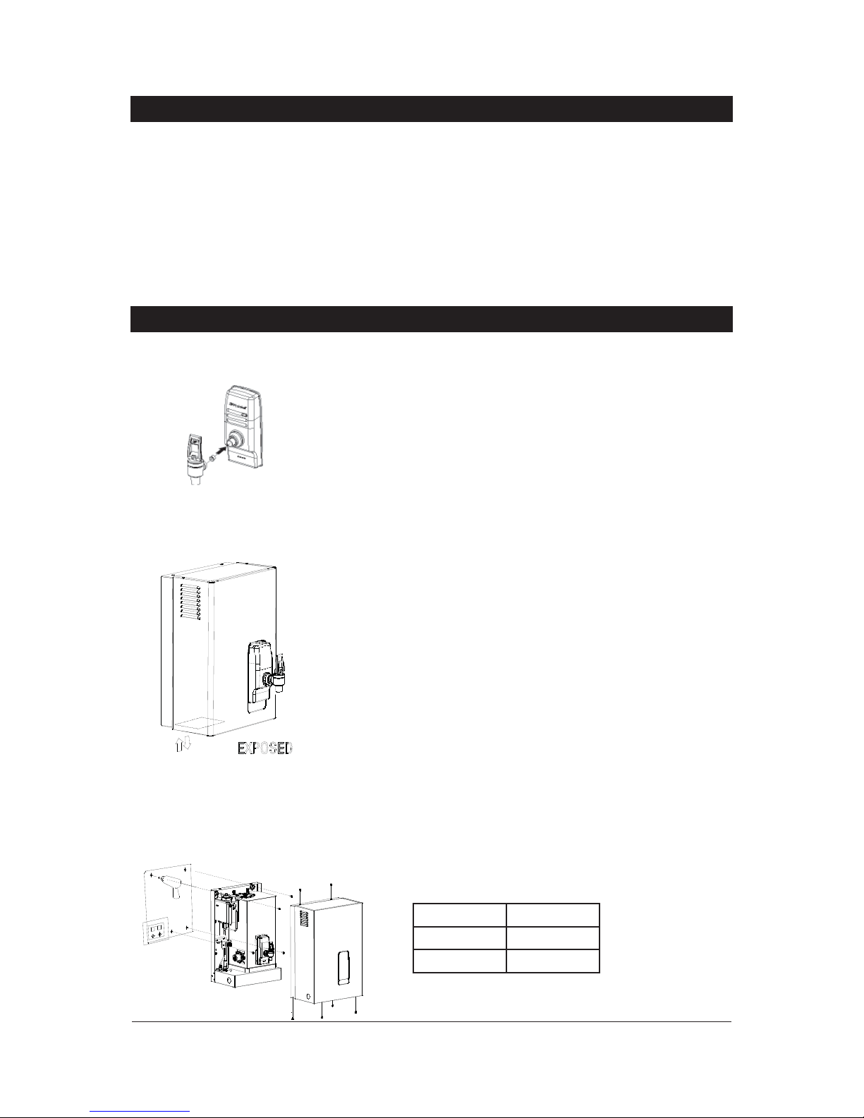
Step 4 - Assembling
Place the heater case back onto the chassis and secure the two top and four
bottom fixing screws.
Screw the tap assembly clockwise onto the tap outlet tube using PTFE tape.
Screw the tap clockwise until the tap assembly touches the fascia without
pressure.
Continue to turn the tap a further one full turn until the tap lever is upright.
Step 5 - Commissioning
Check previous steps. Turn water supply ON, check connections for leaks.
Turn tap handle to the “lock down” side and leave open until water starts
flowing from the outlet. Return the handle to the closed position to stop water
flow and turn the handle 180º to the “cup fill” position.
Inlet water temperature 15°C 10°C
15 Litre models 40 minutes 43 minutes
25 Litre models 47 minutes 50 minutes
40 Litre models 60 minutes 64 minutes
Installation Procedures continued
Blue
Green
Red
Page 7

Autoboil - Installation & Operating Instructions - 81355 - May 2012 v1.01 Page 7 of 12
Problem Solving
Operating procedures
Tap Operation
Autoboil is fitted with a two-way safety tap.
The tap assembly has two positions, one is the “cup fill” quick return mode.
This operation is achieved by having the handle with the curved cam at the
base of the tap handle facing you. When the handle is released this mode
allows instant water cutoff.
The second mode is “pot fill”, to use this position rotate the handle 180º
from the “cup fill” side so a flat face cam is showing at the handle base. This
operation allows a vessel to be filled without holding your hand where it may
be affected by steam.
“Pot fill” position
“Cup fill” position
Symptom Possible Cause Solution
Fails to dispense water.
Water isolating valve turned off.
Blocked filter, blocked meter tube,
blocked strainer, jammed ball valve
assembly, airlock in transfer tube.
Check water supply valve.
Contact The Zenith Heaters Limited
service dept.
Water not boiling.
No power.
Faulty thermostat, faulty element,
faulty cutout, faulty contactor.
Check power supply.
Contact The Zenith Heaters Limited
service dept.
Runs out of boiling water and fails to
refill.
Outlet tap drips.
Overflow from vent.
Excessive steam from vent.
Power “on” but no heat.
Overload repeatedly tripping with
excessive steam.
Overload repeatedly tripping without
excessive steam.
Internal adjustment.
Contact The Zenith Heaters Limited
service dept.
Page 8

Page 8 of 12 Autoboil - Installation & Operating Instructions - 81355 - May 2012 v1.01
Turn power on. After a short time, boiling water will be available and will be
maintained close to boiling point thereafter. Initial heating periods are:
Reading the Display Screen
Power On
When the ‘Power On’ lamp is illuminated this indicates that the power is
connected and turned on and that the heater is operating normally.
Cleaning Case
Do not use strong, corrosive, spray or abrasive cleaners. Clean the case with a
soft cloth or brush and mild soap and water.
End of life disposal
Operating procedures continued
power on
indicator
In order to help preserve our environment we ask that you dispose of this
product correctly. Please contact your local city council for collection centre
details.
Page 9

Autoboil - Installation & Operating Instructions - 81355 - May 2012 v1.01 Page 9 of 12
Mounting Template
Wall template for 15 litre, 25 litre & 40 litre models.
374 (15L, 25L)
499 (40L)
295 (15L, 25L)
420 (40L)
591 (15L, 25L)
771 (25L)
831 (40L)
188 (15L, 25L)
313 (40L)
(NOT TO SCALE)
Page 10

Page 10 of 12 Autoboil - Installation & Operating Instructions - 81355 - May 2012 v1.01
Connecting John Guest Fittings
Spare Parts List
Key Part Description
1 90096NZ Cistern Lid Clamp Kit
2 90140NZ Overload Kit
3 90120NZ Disc, Capsule, Lid, Gasket Kit
4 90490NZ Gasket Kit
5 90121NZ Cistern Lid Gasket Kit
6 90083NZ Float Valve Kit
7 90069NZ Jumper Valve kit
8 90496NZ O-ring Kit
9 90102NZ Cistern Float S/Nut Kit
10 90495NZ Banjo Screw Kit
11 90110NZ Fascia Light Kit
12 90501NZ Tap Top Kit
13 90499NZ Fascia Lens Kit
14 90494NZ Metering Tube Kit 2400 w
90527NZ Metering Tube Kit 3600 w
90526NZ Metering Tube Kit 6000 w
15 90502NZ Tap Assembly Complete
16 90081NZ Thermostat Kit 2-25 ltr
90080NZ Thermostat Kit 40 ltr
17 90491NZ Clean Hole Cover Kit
18 90123NZ Element Kit 2400 w / 240 v
90124NZ Element Kit 3600 w / 240 v
90125NZ Element Kit 3000 w / 240 v
19 90107NZ Filter Cold Inlet kit
20 90492NZ Drain Cap and Seal Kit
21 90174NZ Contactor Kit 240 v CL01A310TR
Page 11

Autoboil - Installation & Operating Instructions - 81355 - May 2012 v1.01 Page 11 of 12
Exploded View
Page 12

Page 12 of 12 Autoboil - Installation & Operating Instructions - 81355 - May 2012 v1.01
Contact Information
Head Office
Zenith Heaters Limited,
Unit 2/15 Moselle Avenue,
Henderson.
Auckland. 0610
New Zealand.
www.zenithheaters.co.nz
Telephone: 0800 558055
Facsimile: 0800 559055
Registering your product:
Registering your Zenith installation on the Zenith Heaters Limited website may help to establish date of
installation, should it become necessary to service the appliance, under the terms of Zenith Heaters Limited
warranty. To register your installation go to www.zenithheaters.co.nz and look under the heading “Warranty”.
As Zenith Heaters Limited policy is one of continuous product improvement, changes to specifications may be
made without prior notice. Images in this booklet have been modified and may not be true representations of the
finished goods.
In order to help preserve our environment we ask that you dispose of this product correctly. Please contact your
local city council for collection centre details.
Normal
warranty
Extended warranty
12 Mths 24 Mths 36 Mths 48 Mths 60 Mths
Domestic
HydroTap
Parts & Labour Parts & Labour
replacement
@25%rrp
replacement
@33%rrp
replacement
@50%rrp
HydroBoil Parts & Labour Parts & Labour
replacement
@25%rrp
replacement
@33%rrp
replacement
@50%rrp
AutoBoil Parts & Labour Parts only
replacement
@25%rrp
Commercial
HydroTap
Parts & Labour Parts & Labour
All other Parts & Labour
 Loading...