

Zenitel Phontech MPA 1600 Series, Phontech MPA 1606, Phontech MPA 1601, Phontech MPA 1604, Phontech MPA 1602 User Handbook Manual
...
USER HANDBOOK
MPA 1600
MARITIME: COMMUNICATION SYSTEMS


Amendment Record
Handbook page
1 of 89
09
2019.8.6
08 2016.09.06 Added 1605,1606 and
Doc no. A100K11944 /
4000017956
HKL
ASK
RBH SEH
1643, updated IP rating
07 2015.09.30 CN00550:
ASK SEH
Update, Service and
Warranty, Utilization
06 2015.03.19 Unfinished Revision -- --
05 2014.05.02 CN00344: Release
ASK -p/n 4000017956
Version Issue Date Reason for issue Made by Approved by

MPA 1600 Handbook contents:
Handbook page
2 of 89
Handbook page:
Service and Warranty …………
Utilization ……………………………………………………………………………………...…....…………… 5
SYSTEM DESCRIPTION (03118-000-DE) …………………………….……..……………………... 6
− CONTENTS ………………………………………………………………………..……………….……. 7
− 1. INTRODUCTION ……………………………………………………………..……………..…….…. 8
− 2. GENERAL DESCRIPTION ……………………………………………………………..……………. 8
2.1 MPA 1600 OPERATION UNIT ……………………………………………………………..…. 8
2.2 MPA 1601 PA CONTROL UNIT …………………………………………………………….... 9
2.3 MPA 1604 PA CONTROL UNIT ………………………………………………………………. 9
2.4 MPA 1603 GA ALARM PANEL ……………………………………………………...……….. 9
2.5 MPA 1605 GA ALARM PANEL ……………………………………………………………..... 10
2.6 MPA 1606 GA ALARM PANEL ……………………………………………………………..... 10
2.7 MPA 1606 GA ALARM PANEL ……………………………………………………………..... 11
2.8 MPA 1602 PA ENTERTAINMENT UNIT ….…………………………………………………. 11
2.9 TERMINAL BOARD ………………………..…………………………………………………. 11
2.10 AMPLIFIERS …………………...………………………………………………………..……. 12
2.11 LOUDSPEAKERS ………………………...……………………………………………………. 12
2.12 TYPE NUMBER / SYSTEM IDENTIFICATION …………………..…………………………. 12
− 3. TECHNICAL DATA ……………………………………………………………..…………...……. 12
3.1 MPA 1600 OPERATION UNIT ………………………………………………………………. 12
3.2 MPA 1601 PA CONTROL UNIT ………………………………………………………….….. 13
3.3 MPA 1604 PA CONTROL UNIT ………………………………………………………….….. 13
3.4 MPA 1603 GA ALARM PANEL ………………………………………………………….….. 13
3.5 MPA 1605 GA ALARM PANEL ………………………………………………………….….. 13
3.6 MPA 1606 GA ALARM PANEL ………………………………………………………….….. 14
3.7 MPA 1643 GA ALARM PANEL ………………………………………………………….….. 14
3.8 AMPLIFIERS …………………...…………………………………………………………..…. 14
3.9 CABINETS ……………………...…………………………………………………………..…. 16
− 4. PERFORMANCE ………...………………………………………………………..……………..…. 16
4.1 GENERAL ALARM ……………………………………………………………………..……. 16
4.2 FEEDBACK COUNTERMEASURES ………………………………………………….……. 16
− 5. REDUNDANCY ………...………….……………………………………………..…………..……. 17
5.1 CENTRAL EQUIPMENT ..…….…………………………………………………………..…. 17
5.2 LOUDSPEAKER DISTRIBUTION NETWORK ..….…………………………………………. 17
5.3 ALARM PANEL ………….…….…………………………………………………………..…. 17
5.4 CONTROL UNIT ..…………..….…………………………………………………………..…. 17
− 6. EXTERNAL INTERFACES ..……….……………………………………………..……………..…. 18
6.1 GENERAL ALARM INTERFACE TO SHIPS WHISTLE / SIREN ...…………………….…. 20
6.2 MUTE OF EXTERNAL GENERAL ALARM DURING EMERGENCY PA …………….…. 20
6.3 GENERAL ALARM WARNING (FLASHING) LIGHTS …...…………………………….…. 20
6.4 ENTERTAINMENT MUTE PA / GA ..……………………………………………………..…. 20
6.5 VOLUME OVERRIDE …………..………………...………………………………………..…. 20
6.6 POWER FAILURE ..…………………………..……………………………………………..…. 20
6.7 GENERAL WARNING ...……………………..……………………………………………..…. 21
…………………………………………………………..………................. 5
INSTALLATION PROCEDURE (03118-000-IS) …………………….…..…………........................ 22
− CONTENTS …………………………………….…………………………………..……………………. 23
− 1. INTRODUCTION ………………………….…………………………………..……………..………. 24
1.1 PA CONFIGURATION, CARGO VESSELS ………………………………………………..…. 24
1.2 PA CONFIGURATION, PASSENGER VESSELS ..………………………………………….... 24
1.3 PA CONFIGUARTION, ALL VESSELS ………………………………………………………. 24
1.4 TYPE NUMBER / SYSTEM CONFIGURATION ..…………………………………...……….. 24
− 2. INSTALLATION GUIDE ………………………………………………………………..……………. 24
2.1 PLANNING ………………………………………………………………………………..……. 24
2.1.1 General …………………………….…………………………………………………..….. 24
2.1.2 Loudspeaker selection / SPL …………………………….……….……………………….. 28

2.1.3 Amount of loudspeakers ….….…….……………………………………………….…….. 28
Handbook page
3 of 89
2.1.4 Cable arrangeme
2.1.5 Zones ……………………………….…………………………………………………….. 29
2.1.6 Amplifiers ………………………….…………………………………………………….. 29
2.1.7 Short circuit protection …………….…………………………………………………….. 30
2.1.8 Compass Safe Distance …………….…………………………………………………….. 30
2.2 GENERAL ALARM ADJUSTMENT ………………………………………………………….. 30
2.3 FEEDBACK / INTERFERENCE CANCELLATION ..…………..…………………………….. 31
2.3.1 Local Mute ……..………………….…………………………………………………..….. 31
2.3.2 Speech Delay …………………………………………….……….……………………….. 31
2.4 POWER ……………………………...………………………………………………………….. 32
2.5 GLANDS ………….………………...………………………………………………………….. 32
2.6 FERRULING ………………………...………………………………………………………….. 32
2.7 MARKING …………………………...………………………………………………………….. 32
2.8 FASTENING ………………………...………………………………………………………….. 32
2.9 PRESERVATION …………………...………………………………………………………….. 32
2.10 CABLE REQUIREMENTS ….……...………………………………………………………….. 33
nt ……..…….…….…………………………………………………….. 28
OPERATION PROCEDURE (03118-000-OP) ……………..…………….………………..………... 34
− CONTENTS ………………………………….………………………………………..…………………. 35
− 1. INTRODUCTION ………………………………………………………….……..……………..……. 36
− 2. OPERATING DESCRIPTION ……………………………………………………………..…………. 36
2.1 EMERGENCY PAGING ………..……………………………………………………..………. 36
Figure 2-1 ……..………………….……………………………………………………..…..….. 37
2.2 PAGING (Normal Paging) ………………………………………………………………………. 37
Figure 2-2 ……..………………….……………………………………………………..…..….. 38
2.3 ALARM (General Alarm) ……...………………………………………………………………. 38
Figure 2-3 ……..………………….……………………………………………………..…..….. 39
Figure 2-4 ……..………………….……………………………………………………..…..….. 39
2.4 PRIORITY ………………...……..………………………………………………………………. 39
2.5 ZONES …………………………..………………………………………………………………. 40
2.6 LOCAL MUTE …………...……..………………………………………………………………. 40
2.7 VOLUME OVERRIDE ……..…..………………………………………………………………. 40
2.8 ALARM PRIORITY ………...…..………………………………………………………………. 40
2.9 ATTENTION TONE …...………..………………………………………………………………. 40
2.10 ENTERTAINMENT ……..……..………………………………………………………………. 41
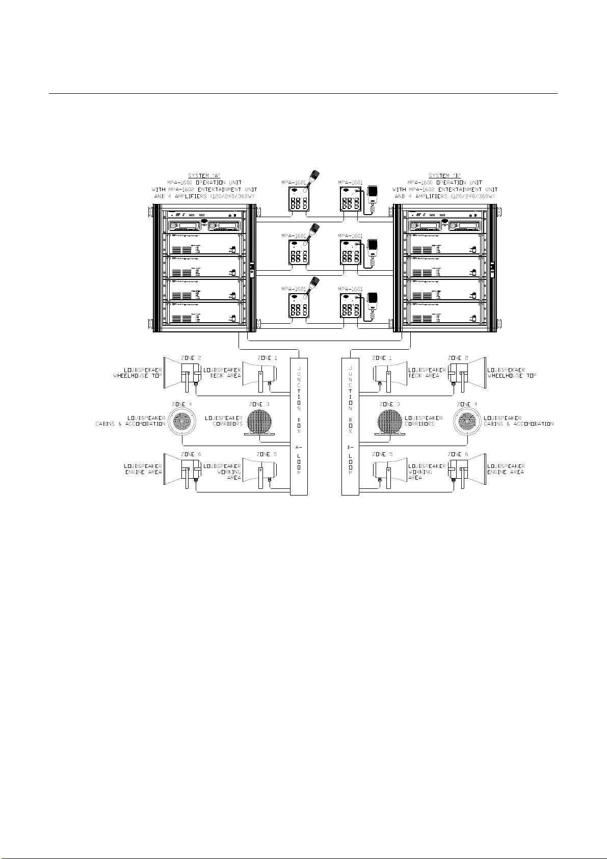
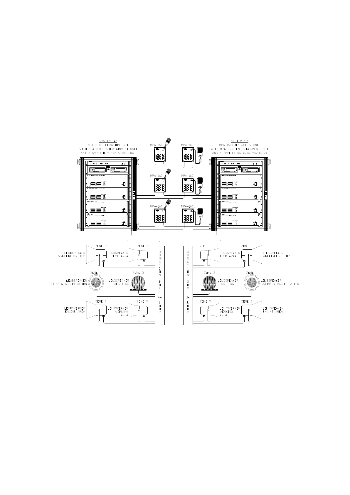
MPA 1600 SYSTEM, block diagram (03118-100-BD) …..………………………..………..….…... 42
MPA 1600 SYSTEM, external connection (03118-025-EC) ………….…………………………... 43
− 1 of 8: Control Units and Alarm Panel Connection – Single & Dual system “A” …………………….….. 43
− 2 of 8: Control Units and Alarm Panel Connection – Dual system “B” ………………………………….. 44
− 3 of 8: Zone and Loudspeaker distribution – Single & Dual system “A” ……………….……………….. 45
− 4 of 8: Zone and Loudspeaker distribution – Dual system “B” ………………………….……………….. 46
− 5 of 8: Alarm Control inputs and outputs – Single & Dual system “A” ………………………………….. 47
− 6 of 8: Alarm Control inputs and outputs – Dual system “B” …………………………………………….. 48
− 7 of 8: Intercom and PABX interconnection – Single & Dual system “A” ……………………………….. 49
− 8 of 8: System interconnection – Dual system “A” and “B” …………………………………………….. 50
COMMISSIONING PROCEDURE (03118-100-CO) …..…………….…………………..….……. 51
− LIST OF CONTENT …………………………………………………………………………………….. 51
− 1. SCOPE ................................................................................................................................................... 52
− 2. TERMINOLOGY .................................................................................................................................. 52
2.1 Abbreviations ............................................................................................................................. 52
− 3. REFERENCE DOCUMENTS ……....................................................................................................... 52
− 4. INTRODUCTION …….......................................................................................................................... 53
− 5. BRIEF SYSTEM DESCRIPTION ....................................................................................................... 53
5.1 General ..................................................................................................................................…… 53
5.2 Central equipment ........................................................................................................................ 53
5.3 Access & Control panels ............................................................................................................ 53
− 6. TEST PLAN ......................................................................................................................................... 54
6.1 Test philosophy ........................................................................................................................... 54

6.2 Scope of test ...................................................
Handbook page
4 of 89
− 7. SPECIFIC TEST PROCEDURE .......................................................................................................... 54
7.1 General checks ............................................................................................................................. 54
7.2 Workmanship .............................................................................................................................. 55
− 8. FUNCTIONAL TESTING OF UNITS ............................................................................................... 55
8.1 MPA 1600 Operation unit ........................................................................................................... 55
8.2 MPA 1601 Access units ............................................................................................................. 55
8.2.1 Normal Paging .................................................................................................................... 55
8.2.2 EMergency Paging ............................................................................................................. 55
8.2.3 Indicators ............................................................................................................................. 55
8.2.4 Priority by normal paging "PA" ......................................................................................... 56
8.2.5 External Control outputs .................................................................................................... 57
8.3 Zones ........................................................................................................................................... 57
8.4 MPA 1603 Alarm Panel .............................................................................................................. 57
8.4.1 Alarm setting ...................................................................................................................... 57
8.4.2 External Control outputs .................................................................................................... 58
8.5 Paging during alarm (General Alarm) ........................................................................................ 58
8.6 Failure / warning outputs ............................................................................................................. 58
8.7 Redundancy test ......................................................................................................................... 58
8.8 Sound Pressure Level ................................................................................................................. 58
− 9. TEST INSTRUMENTS ....................................................................................................................... 60
− 10. PARTICIPANTS ................................................................................................................................ 60
− 11. PUNCH LIST ...................................................................................................................................... 61
............................................................................. 54
MPA 1600 OPERATION UNIT, mechanical layout (03118-001-ML) ……...……..……….….... 62
MPA 1601 CONTROL UNIT, Ver. 05827, mechanical layout (03118-040-ML) …..….……... 63
MPA 1601 CONTROL UNIT, Ver. 05827, external connection (03118-040-EC) …….……... 64
MPA 1604 CONTROL UNIT Ver. 05827, mechanical layout (03118-038-ML): .…................. 65
MPA 1604 CONTROL UNIT Ver. 05827, external connection (03118-038-EC): .…............... 66
MPA 1603 ALARM PANEL Ver. 05827, mechanical layout (03118-041-ML): .…….….......... 67
MPA 1603 ALARM PANEL Ver. 05827, external connection (03118-041-EC): .…….…......... 68
MPA 1600 SYSTEM, 1610 CABINET, mechanical layout (03118-125-ML) ……………..….... 69
PA-9312/24/36/48 COMMERCIAL PA AMPLIFIER, specification ……………..……..…........ 70
PA-9312/24/36/48 PUBLIC ADDRESS POWER AMPLIFIER, operation manual ….......... 73
POWER AMPLIFIER 1670, data sheet …………………………………………….……………....…... 88

SERVICE AND WARRANTY
Handbook page
5 of 89
Zenitel warrants that the product sold by Zenitel substantially confirm with said products
written specifications for a period of up to 24 (twenty-four) months after invoice date.
Notice of claims shall be made to Zenitel within 30 (thirty) calendar days after receipt of the
product. The claim must be registered either online at www.zenitel.com/customer-service/
claims or on RMA form provided by Zenitel through claims@zenitel.com.
a) Delivered batteries are generally not covered by Zenitel warranty terms.
b) Buyer also has an option to extend the 24 (twenty-four) (24) months warranty time at a
separate charge. The details for this are found in the valid pricelist, and has to be settled
before delivery of the products.
c) The product must have been properly stored, installed and used to claim under the warranty.
d) Within the warranty period, the Buyer shall give prompt written notice, if any part of the
product is proven defective in material or workmanship, online either at www.zenitel.com/
customer-service/claims or on RMA form provided by Zenitel through claims@zenitel.com.
e) Zenitel shall not be liable to Buyer or third party claims relevant to accidental or improper
use, wrong installation performed by uncertified technicians, from damage to the product, or
from other circumstances beyond Zenitel’s control.
f) The product shall be returned to Zenitel, subject to prior written consent from Zenitel, in the
form of a RMA reference number (Return Merchandise Authorization). The product shall be
returned immediately, and no later than 60 days after RMA reference number has been
received. Returned products in lack of such reference, will not be accepted by Zenitel and
returned to Buyer at Buyer’s cost.
g) The cost of the return shipment is to be covered by the Buyer. Zenitel will cover the cost of
shipment for replacement parts.
h) Zenitel decides whether a defective part shall be replaced, returned to factory for repair or
being repaired onboard the vessel or on site.
i) If repair/change of parts is to be done onboard the vessel or on site, Zenitel shall approve by
certification the company/technician doing the labor on their behalf.
After the repair is done onboard the vessel or on site, Zenitel will, based on the repair report,
decide if the mentioned repair is a warranty matter or not. If it is a warranty matter, Zenitel
will cover labor time up to 4 hours, and spare parts to correct the fault. Service technician’s
preparation, travelling time and travelling expenses, if any, are for the account of the Buyer.
j) If Zenitel has to deliver new parts to solve a warranty matter before the claimed product is
received for inspection and acceptance, Zenitel will invoice the new part with standard order
terms at shipment, and then issue a credit note when the defective part has been received by
Zenitel and approved as warranty by quality department.
k) Repair or replacement of parts in a configuration done by Zenitel during the warranty period,
has no effect on the expiration of the warranty for a complete project delivery, and does not
give rise to a renewal or extension of the warranty period for the configuration.
UTILIZATION:
This equipment is not to be disposed in normal waste, but be handled in accordance with
applicable waste disposal regulations in the country where the equipment is used
Doc.No.: 03118-000-DE
Handbook page
6 of 89
MPA 1601
Syst
. BSyst. A
DIM
1
4
G C
2
5
PTT
3
6
MPA 1601
Syst
. BSyst. A
1
4 DIM
G C2
5
PTT
3
6
MPA 1601
Syst
. BSyst. A
DIM
1
4
G C
2
5
PTT
3
6
MPA 1601
Syst. BS
yst. A
DIM
1
4
G C
2
5
PTT
3
6
MPA 1601
Syst. BS
yst. A
1
4 DIM
G C2
5
PTT
3
6
MPA 1601
Syst. BS
yst. A
DIM
1
4
G C
2
5
PTT
3
6
Page 1 of 16

CONTENTS
Handbook page
7 of 89
Doc.No.: 03118-000-DE
CONTENTS
1. INTRODUCTION ............................................................................................................................ 3
2. GENERAL DESCRIPTION ............................................................................................................. 3
2.1. MPA 1600 OPERATION UNIT ............................................................................................... 3
2.2. MPA 1601 PA CONTROL UNIT ............................................................................................. 4
2.3. MPA 1604 PA CONTROL UNIT ............................................................................................. 4
2.4. MPA 1603 GA ALARM PANEL .............................................................................................. 4
2.5. MPA 1605 GA ALARM PANEL .............................................................................................. 5
2.6. MPA 1606 GA ALARM PANEL .............................................................................................. 5
2.7. MPA 1643 GA ALARM PANEL .............................................................................................. 6
2.8. MPA 1602 PA ENTERTAINMENT UNIT .............................................................................. 6
2.9. TERMINAL BOARD ................................................................................................................ 6
2.10. AMPLIFIERS ........................................................................................................................ 7
2.11. LOUDSPEAKERS ................................................................................................................. 7
2.12. TYPE NUMBER / SYSTEM IDENTIFICATION ................................................................ 7
3. TECHNICAL DATA ........................................................................................................................ 7
3.1. MPA 1600 OPERATION UNIT ............................................................................................... 7
3.2. MPA 1601 PA CONTROL UNIT ............................................................................................. 8
3.3. MPA 1604 PA CONTROL UNIT ............................................................................................. 8
3.4. MPA 1603 GA ALARM PANEL .............................................................................................. 8
3.5. MPA 1605 PA CONTROL UNIT ............................................................................................. 8
3.6. MPA 1606 PA CONTROL UNIT ............................................................................................. 9
3.7. MPA 1643 PA CONTROL UNIT ............................................................................................. 9
3.8. AMPLIFIERS ............................................................................................................................ 9
3.9. CABINETS .............................................................................................................................. 11
4. PERFORMANCE ........................................................................................................................... 11
4.1. GENERAL ALARM ............................................................................................................... 11
4.2. FEEDBACK COUNTERMEASURES ................................................................................... 11
5. REDUNDANCY ............................................................................................................................. 12
5.1. CENTRAL EQUIPMENT ....................................................................................................... 12
5.2. LOUDSPEAKER DISTRIBUTION NETWORK .................................................................. 12
5.3. ALARM PANEL ..................................................................................................................... 12
5.4. CONTROL UNIT .................................................................................................................... 12
6. EXTERNAL INTERFACES .......................................................................................................... 13
6.1. GENERAL ALARM INTERFACE TO SHIPS WHISTLE / SIREN ..................................... 15
6.2. MUTE OF EXTERNAL GENERAL ALARM DURING EMERGENCY PA ...................... 15
6.3. GENERAL ALARM WARNING (FLASHING) LIGHT ...................................................... 15
6.4. ENTERTAINMENT MUTE, PA/GA ..................................................................................... 15
6.5. VOLUME OVERRIDE ........................................................................................................... 15
6.6. POWER FAILURE ................................................................................................................. 15
6.7. GENERAL WARNING .......................................................................................................... 16
.......................................................................................................................................... 2
Page 2 of 16

1. INTRODUCTION
Handbook page
8 of 89
Doc.No.: 03118-000-DE
The MPA-sy
stem is a marine and offshore Public Address system. It meets the requirements for
PA/GA, and entertainment, distribution onboard ships and mobile offshore units. The system conforms
to SOLAS, IMO and IEC regulations. Based on modular design and flexible configuration, it covers a
wide range of installation complexities. Ranging from, small single loop systems, to large duplicated
systems.
2. GENERAL DESCRIPTION
2.1. MPA 1600 OPERATION UNIT
The MPA 1600 Operation Unit is the system central logic controller in the MPA-system. It is designed
for 19" 1 Unit rack mounting.
FEATURES:
- Up to 6 zones, selectable in any configuration.
- Up to 6 MPA 1601 / 1604 /1605 / 1606 / 1643 Control Units or
- Up to 6 MPA 1603 Alarm Panels in combination with MPA 1601 panels.
- Up to 2 emergency microphones.
- External paging facility (from ICS6200/DICS6100/PABX etc.).
- Prepared for duplication - A/B dual system, with synchronisation.
- Interfaces for manual and/or automatic alarms.
- 2 entertainment sources, with free zone selection (MPA 1602)
- Signal processing capabilities.
- Configurable priority levels.
- 7 audio outputs, with unlimited amplifier expansion.
- Facility for muting of local loudspeaker during paging.
- Override of entertainment volume-controls during paging.
- Output for mute of external GA system.
- Output for activation of external GA system.
- Synchronisation with external GA tones.
- Up to 8 different alarms in the system.
- Up to 6 MPA 1603 Alarm Panels, with up to 4 different alarms.
- Chime/”ding-dong” generator.
- Alarm light signal activation.
- Mute of external alarm facility.
- Built-in loudspeaker, to monitor activity on zones.
INDICATORS
- Power status indicator with a red/green led.
- Warning/Info indication with a red/green led.
- Link/Tx indication with a green led.
- PA led indication with a green led.
- Alarm indication with a green led.
- Zone status indication with 6 red/green leds.
- MPA 1601/1603/1605/1606/1643 User status indication with 6 red/green leds.
Page 3 of 16

Doc.No.: 03118-000
Handbook page
9 of 89
-DE
2.2. MP
A 1601 PA CONTROL UNIT
The MPA 1601 is a full facility operator control unit in the MPA system. It is designed for flush
mounting.
FEATURES:
- Microphone options are Gooseneck, or Handheld.
- RS485 data communication with MPA1600 Operation Unit.
- 6 Zone-selection keys.
- PA (normal paging) key
- Emergency PA key marked with red colour
- Emergency PA key is protected against unauthorised use by means of time-trap functionality
(the Emergency PA key must be held for 1 sec. before activation.
- Dimmer key
- Status-Led for system A and system B.
- Led-indicators for all keys.
- Dimmable Backlight and indication leds
- Local mute relays.
2.3. MPA 1604 PA CONTROL UNIT
The MPA 1604 is an operator control unit without Emergency PA facility in the MPA system. It is
designed for flush mounting.
FEATURES:
- Microphone options are gooseneck, or handheld.
- RS485 data communication with MPA1600 Operation Unit.
- 6 Zone-selection keys.
- PA (normal paging) key.
- Status-Led for system A and system B.
- Led-indicators for all keys.
- Local mute relays.
2.4. MPA 1603 GA ALARM PANEL
The MPA 1603 is a manual alarm control unit in the MPA system. It is designed for flush mounting.
FEATURES:
- RS485 data communication with MPA1600 Operation Unit.
- 4 Alarm keys marked with the text “ALARM” and red colour
- Cancel key.
- Protection against unauthorised use by means of time-trap functionality (the alarm keys and the
Cancel keys must be held for 1 sec. before activation).
- 6 leds indicating alarm status in each zone.
- Led indicators for all keys.
- Dimmable backlight and leds, remotely controlled from the adjacent MPA 1601 Control Unit.
Page 4 of 16

Doc.No.: 03118-000
Handbook page
10 of 89
-DE
2.5. MP
A 1605 GA ALARM PANEL
The MPA 1605 is a full facility operator control unit with manual alarm controls in the MPA system. It
is designed for desk-top mounting/placement.
FEATURES:
- Microphone options are Gooseneck, or Handheld.
- RS485 data communication with MPA1600 Operation Unit.
- 6 Zone-selection keys.
- 4 Alarm keys marked with the text “ALARM” and red colour
- Cancel key.
- PA (normal paging) key
- Emergency PA key marked with red colour
- Protection against unauthorised use by means of time-trap functionality (the EM/alarm keys
and the Cancel keys must be held for 1 sec. before activation).
- Dimmer key
- Status-Led for system A and system B.
- Led-indicators for all keys.
- Dimmable Backlight and indication leds
- Local mute relays.
2.6. MPA 1606 GA ALARM PANEL
The MPA 1606 is a full facility operator control unit with manual alarm controls in the MPA system. It
is designed for flush/19” rack mounting.
FEATURES:
- Microphone options are Gooseneck, or Handheld.
- RS485 data communication with MPA1600 Operation Unit.
- 6 Zone-selection keys.
- 4 Alarm keys marked with the text “ALARM” and red colour
- Cancel key.
- PA (normal paging) key
- Emergency PA key marked with red colour
- Protection against unauthorised use by means of time-trap functionality (the EM/alarm keys
and the Cancel keys must be held for 1 sec. before activation).
- Dimmer key
- Status-Led for system A and system B.
- Led-indicators for all keys.
- Dimmable Backlight and indication leds
- Local mute relays.
Page 5 of 16

Doc.No.: 03118-000-DE
Handbook page
11 of 89
2.7. MP
The MPA 1643 is a full f
A 1643 GA ALARM PANEL
acility operator control unit with manual alarm controls in the MPA system. It
is designed for wall mounting in EX areas.
The unit consists of following:
• Interface PCB for buttons.
• Interface PCB for LEDs.
• Standard PCB for 1601 User panel.
• Standard PCB for 1603 Alarm panel.
• Din rail mounted safety barriers for buttons, LEDs and audio.
FEATURES:
- Microphone options are Gooseneck, or Handheld.
- RS485 data communication with MPA1600 Operation Unit from junction box with controller
boards in safe area. (Barriers in this box).
- 6 Zone-selection keys.
- 4 Alarm keys marked with the text “ALARM” and red colour.
- Cancel key.
- PA (normal paging) key.
- Emergency PA key marked with red colour.
- Protection against unauthorised use by means of time-trap functionality (the EM/alarm keys
and the Cancel keys must be held for 1 sec. before activation).
- Dimmer key.
- Status-Led for system A and system B.
- Led-indicators for all keys.
- Dimmable Backlight and indication LEDs.
2.8. MPA 1602 PA ENTERTAINMENT UNIT
The MPA 1602 is a PA Entertainment Unit in the MPA system. It is designed for 19” 2 Unit rack
mounting. And it is electrically isolated.
FEATURES:
- Up to 2 CD-players, or one CD-player and one external audio (TV/Video etc.)
- Configurable entertainment audio in any 6 zones per source.
- Keypad for zone selection and status indication.
- Entertainment / volume override during PA messages.
2.9. TERMINAL BOARD
Because of the high number of interfaces in the MPA system, a terminal board is necessary to interface
the MPA 1600 with ship-cables. See the attached drawing 03118-025-EC and 03118-000-IS for
connection and installation details.
Page 6 of 16

Doc.No.: 03118-000-DE
Handbook page
12 of 89
2.10. AM
The MPA s
ystem is designed to be used with a number of audio amplifiers. The amplifiers can be
PLIFIERS
PA6312 (120W), PA6324 (240W), PA6336 (360W) or PA6348 (480W).
FEATURES:
- Thermal and overload protection, balanced input.
- Dual power input (AC primary / DC backup).
- (Gain adjustment 0 – [-12] service mode).
2.11. LOUDSPEAKERS
A PA/GA system like the MPA 1600 will utilize a wide variety of loudspeakers in the distribution
network. Subjects like environment, topology and sound pressure requirement will determine what
kind of loudspeaker type and size should be used in the specific areas.
To comply with the environment requirement all loudspeakers used in a PA/GA system must be
approved according to relevant parts of IEC60945 or similar.
The topology and sound pressure requirement will be decisive for the amount of loudspeakers in the
different are
as, the loudspeaker type, their power rating and tapping.
See document 03118-000-IS for detailed loudspeaker selection information.
2.12. TYPE NUMBER / SYSTEM IDENTIFICATION
In order to recognise and identify different version of an MPA1600 system there is an identification
system marked on all cabinets.
This system is built up as a combination of rack type and amount and type of amplifiers.
3. TECHNICAL DATA
3.1. MPA 1600 OPERATION UNIT
- 19" 1 Unit rack mounting unit.
- Operating voltage: Dual 24VDC – primary (AC through
integrated Power supply module) / backup
- Current drain maximum: 5A
- Microphone input level: 5mV.
- External PA input level: 0 dBu typical (configurable)
- External entertainment input level: 0 dBu typical (configurable)
- Audio outputs to amplifiers: 0 dBu typical (configurable)
- Size: 44 x 483 x 206mm (HxWxD)
- Weight: 3kg
- Ingress Protection (stand-alone) (IP): 20
- Compass safe distance: Ref Cabinet data
Page 7 of 16

Doc.No.: 03118-000-DE
Handbook page
13 of 89
3.2. MP
-
A 1601 PA CONTROL UNIT
Outer dimensions: 144 x 144mm.
- Operating voltage: 24VDC supplied from the MPA1600
Operation Unit.
- Current drain maximum: 300mA. (integrated in the MPA 1600)
- Microphone input level: 10mV typical (dynamic mic.)
- Ingress Protection (IP): 22
- Compass safe distance (standard): 80cm
- Compass safe distance (steering): 50cm
3.3. MPA 1604 PA CONTROL UNIT
Outer dimensions: 144 x 144mm.
-
- Operating voltage: 24VDC supplied from the MPA1600
Operation Unit.
- Current drain maximum: 300mA. (integrated in the MPA 1600)
- Microphone input level: 10mV typical (dynamic mic.)
- Ingress Protection (IP): 22
- Compass safe distance (standard)1: 80cm
- Compass safe distance (steering): 50cm
3.4. MPA 1603 GA ALARM PANEL
- Outer dimensions: 144 x 96mm.
- Operating voltage: 24VDC supplied from the MPA1600
Operation Unit.
- Current drain maximum: 100mA.
- Ingress Protection (IP): 22
- Compass safe distance (standard): 60cm
- Compass safe distance (steering): 40cm
3.5. MPA 1605 PA CONTROL UNIT
- Outer dimensions: 394 x 196 x 57,35 mm.
- Operating voltage: 24VDC supplied from the MPA1600
Operation Unit.
- Current drain maximum: 300mA. (integrated in the MPA 1600)
- Microphone input level: 10mV typical (dynamic mic.)
- Ingress Protection (IP): 22
- Compass safe distance (standard): 80cm
- Compass safe distance (steering): 50cm
1
(The uni
t is physically identical to MPA 1601)
Page 8 of 16

Doc.No.: 03118-000
Handbook page
14 of 89
-DE
3.6. MP
A 1606 PA CONTROL UNIT
- Outer dimensions: 483 x 177 x 55 mm.
- Operating voltage: 24VDC supplied from the MPA1600
Operation Unit.
- Current drain maximum: 300mA. (integrated in the MPA 1600)
- Microphone input level: 10mV typical (dynamic mic.)
- Ingress Protection (IP): 22
- Compass safe distance (standard): 80cm
- Compass safe distance (steering): 50cm
-
3.7. MPA 1643 PA CONTROL UNIT
- Outer dimensions: 160 x 360 mm.
- Operating voltage: 24VDC supplied from the MPA1600
Operation Unit.
- Current drain maximum: 300mA. (integrated in the MPA 1600)
- Microphone input level: 10mV typical (dynamic mic.)
- Ingress Protection (IP): 44
- Compass safe distance (standard): 80cm
- Compass safe distance (steering): 50cm
3.8. AMPLIFIERS
Model: PA-6336
ELECTRICAL
Power output (THD 1%) 360W (RMS)
Max load: 4 ohm (38V)
Frequency Response (+1/-3dB) 70Hz to 20KHz
THD at 1 KHz, Rated Output Less than 1%
HPF -3dB at 400Hz
Signal to Noise Ratio Better than 95dB
Input Sensitivity/Impedance 1V/10K ohm Balanced
Input Level Adjustment (service mode) -12dB to 0dB
GENERAL
Power source (primary) AC 230V (220/240) 50Hz/60Hzor
Dimensions W:482 x H:132 x D:280 mm
Weight 21Kg.
Compass safe distance: Ref Cabinet data
8 ohm (50V)
13,6 ohm (70V)
27,8 ohm(100V)
(primary alternative) AC 115V (110/120)
(backup) DC 24V
Page 9 of 16

Doc.No.: 03118-000
Handbook page
15 of 89
Model: PA-6324
LECTRICAL
E
Power output (THD 1%) 240W (RMS)
Max load: 4 ohm (31V)
21 ohm (70V)
42 ohm(100V)
Frequency Response (+1/-3dB) 70Hz to 20KHz
THD at 1 KHz, Rated Output Less than 1%
HPF -3dB at 400Hz
Signal to Noise Ratio Better than 95dB
Input Sensitivity/Impedance 1V/10K ohm Balanced
Input Level Adjustment (service mode) -12dB to 0dB
GENERAL
Power source (primary) AC 230V (220/240) 50Hz/60Hzor
(primary alternative) AC 115V (110/120)
(backup) DC 24V
Dimensions W:482 x H:132 x D:280 mm
Weight 19Kg.
Compass safe distance: Ref Cabinet data
-DE
Model: PA-6312
ELECTRICAL
Power output (THD 1%) 120W (RMS)
Max load: 4 ohm (25V)
42 ohm (70V)
83 ohm(100V)
Frequency Response (+1/-3dB) 70Hz to 20KHz
THD at 1 KHz, Rated Output Less than 1%
HPF -3dB at 400Hz
Signal to Noise Ratio Better than 95dB
Input Sensitivity/Impedance 1V/10K ohm Balanced
Input Level Adjustment (service mode) -12dB to 0dB
GENERAL
Power source (primary) AC 230V (220/240) 50Hz/60Hzor
(primary alternative) AC 115V (110/120)
(backup) DC 24V
Dimensions W:482 x H:132 x D:280 mm
Weight 14Kg.
Compass safe distance: Ref Cabinet data
Page 10 of 16

Doc.No.: 03118-000
Handbook page
16 of 89
-DE
3.9. CABINETS
Wall cabinet:
Type: Rittal EL – 15U Wall Cabinet
Dimensions W:600 x H:746 x D:615 mm
Weight 110 – 150 kg (equipment dependant).
Compass safe distance (standard): 340 cm
Compass safe distance (steering): 220 cm
Vibration Isolator: 4 x Vibratec A100216-092/6-II
Rack:
Type: Rittal TS8 – 42HE Equipment Rack
Dimensions W:613 x H:2105 x D:830 mm
Weight 200 – 300kg (equipment dependant).
Compass safe distance (standard): 340 cm
Compass safe distance (steering): 220 cm
Vibration Isolator: 4 x Vibratec A100216-092/6-II
4. PERFORMANCE
(Vertical against the wall)
(Supports weight 110 – 150 kg)
(Horizontal against the floor)
(Supports weight 200 – 300 kg)
4.1. GENERAL ALARM
The General Alarm tone in the MPA 1600 system consists of seven short followed by one long tone
burst. Each short tone has approximately 1 sec. duration, each pause between tones approximately 1
sec. and the long tone has 7 sec. duration. The alarm signal sequence is continuously repeated. The
alarm tone is basically generated of a 1000 Hz sinusoidal tone.
The General alarm tone can be adjusted by means of loading different configuration data. Frequencies
between 200 and 2500 Hz can be selected along with triangular or sinusoidal curve form.
The configuration changes require a special administrative tool and are unavailable during normal
operation.
4.2. FEEDBACK COUNTERMEASURES
In the MPA 1600 system there are three different countermeasures available in order to avoid audible
feedback and disturbance during announcements.
− The MPA 1601 and 1604, Control Units are equipped with either a gooseneck or handheld
microphone with close-talk characteristics with excellent background noise suppression capability.
− The MPA 1601 and 1604, Control Units, are equipped with relays for disconnecting loudspeakers
in the close proximity when activated.
− Each audio interface can be programmed to be of a recording type. The message is temporarily
recorded and is automatically played back when the announcement is terminated.
Page 11 of 16

Doc.No.: 03118-000
Handbook page
17 of 89
5. REDUNDANCY
I
n a PA/GA system as the MPA 1600 the design and the installation must be carried out in a way that
the damage of one single failure shall be minimised as far as possible.
In the MPA 1600 such redundancy is achieved by the following measures:
5.1. CENTRAL EQUIPMENT
- All centralized equipment (MPA 1600, Amplifiers etc) is duplicated and physically separated
in different fire zones – System A and B. Ref document. 03118-100-BD and 03118-100-EC.
- The A and B central equipment are connected together with a synchronisation link to
coordinate alarm tone generation and other timing-related functionality. If this synchronisation
link is somehow broken or damaged the systems will work individually.
- The MPA 1601 and 1604, Control Units and MPA 1603, Alarm Panel, are equipped with a
duplicated interface for connection to both systems (A and B). The connection status is
displayed in the System A / B led indicator of the MPA 1601 and 1604.
5.2. LOUDSPEAKER DISTRIBUTION NETWORK
- The loudspeaker distribution network is duplicated and routed separately in different cable
ducts and as physically separated as possible.
- All public areas shall be covered equally from both loudspeaker distribution network.
- All cabins shall be supplied with PA/GA loudspeakers. Minimum requirement is that
neighbouring cabins shall be supplied from different loudspeaker distribution network.
-DE
5.3. ALARM PANEL
In order to have a required redundancy and availability to the General alarm the minimum amount of
MPA 1603 Alarm Panels is two (Alternatively 1605/1606/1643). One shall always be placed on the
Navigation Bridge. At least one more shall be placed in another strategic place as
an alternative
position.
5.4. CONTROL UNIT
In order to have a required redundancy and availability to the Emergency PA, the minimum amount of
MPA 1601 Control Units is two (Alternatively 1605/1606/1643). One shall always be placed on the
Navigation Bridge. At least one more shall be placed in another strategic place as
an alternative
position and where it is deemed necessary.
Page 12 of 16

6. EXTERNAL INTERFACES
Handbook page
18 of 89
Doc.No.: 03118-000
-DE
The MPA 1600 PA/GA sy
stem is equipped with various control outputs for external equipment. This
is intended for additional warnings and indicators. See also doc. 03118-025-EC:
Terminals Name Description Input/output Interface Voltage Current /
1 – 2 0V / AL1 Direct Alarm
3 – 4 0V / AL2 ≈2
5 – 6 0V / AL3 ≈2
7 – 8 0V / AL4 ≈2
9 – 10 0V / AL5 ≈2
11 – 12 0V / AL6 ≈2
13 – 14 0V / AL7 ≈2
15 – 16 0V / AL8 ≈2
17 – 18 +24V / AL1
19 – 20 +24V / AL2
21 – 22 +24V / AL3
23 – 24 +24V / AL4
25 – 26 +24V / AL5
27 – 28 +24V / AL6
29 – 30 ALARM ON Any Alarm ON status Out
31 – 32 ALARM
33 – 34 ALARM
35 – 36 GENERAL
37 – 38 POWER
39 – 40 POWER
41 – 42 -- Not in
43 – 44 TALK USED Any PTT is active output Out
45 – 46 EXT. PA
47 – 48 EXT. PA IN
49 – 50 PA1 / 0V Direct Paging inputs I
51 – 52 PA2 / 0V Dr
53 – 54 PA3 / 0V Dr
55 – 56 PA4 / 0V Dr
57 – 58 PA5 / 0V Dr
59 – 60 PA6 / 0V Dr
61 – 62 PA7 / 0V Dr
63 – 64 PA8 / 0V Dr
65 – 66 +24V / 0V Power output Output Power supply outp
67 – 68 -- Not in
69 – 70 -- Not in
71 – 72 +24V / EM
73 – 74 -- Not in
75 – 76 -- Not in
77 – 78 -- Not in
79 – 80 B-SYSTEM
81 – 82 POWER
83 – 84 AUDIO I
85 – 86 RS485 Bi
ACT
ACT
ACT
ACT
ACT
ACT
SYNC
IN
SYNC OUT
W
ARNING
F
AIL
F
AIL
OUT
(AU
DIO)
(AU
DIO)
PA
SENSOR
in
puts
A
larm status outputs Output Open collector
Alarm sequence input Input Dry contact input ≈20VDC 2 mA
Alarm sequence monitor output Output Dry contact output -- 0.3 A
Error monitoring output Output Dry contact output -- 0.3 A
Power monitoring output, Normally
Closed
Power monitoring output, Normally Open Output Dry contact output -- 0.3 A
Use -- -- -- --
System Audio during PTT/EM PTT Output Galvanically
System Audio for external Paging Input Galvanically
Use -- -- -- - Use -- -- -- --
EM PTT is a
Shorted when system is System B i
dual system configuration
ctive Output Open collector
Use -- -- -- - Use -- -- -- - Use -- -- -- --
n a
USER INTERFACE 1
Input Dry contact input ≈20VDC 2 mA
source/sink
put Dry contact output -- 0.3 A
Output Dry contact output -- 0.3 A
put Dry contact output -- 0.3 A
balanced audio
output
balanced audio input
nput Dry contact input ≈20VDC 2 mA
y contact input ≈20VDC 2 mA
y contact input ≈20VDC 2 mA
y contact input ≈20VDC 2 mA
y contact input ≈20VDC 2 mA
y contact input ≈20VDC 2 mA
y contact input ≈20VDC 2 mA
y contact input ≈20VDC 2 mA
source/sink
Input Dry contact input ≈20VDC 2 mA
Output Power supply output 24VDC 140 mA
nput Electronically
balanced audio input
directional Data communication
tranceiver channel
RS485
0VDC 2 mA
0VDC 2 mA
0VDC 2 mA
0VDC 2 mA
0VDC 2 mA
0VDC 2 mA
0VDC 2 mA
24VDC 40 mA
24VD
24VD
24VD
24VD
24VD
0dBu 230 Ω
0dBu 15 kΩ
ut 24VDC 140 mA
24VDC 40 mA
2Vrms 15k Ω
5V 100 Ω
Impedance
C 40 mA
C 40 mA
C 40 mA
C 40 mA
C 40 mA
Page 13 of 16

Doc.No.: 03118-000
Handbook page
19 of 89
-DE
Terminals Name Description Input/output
87 – 88 POWER
89 – 90 AUDIO Bi
91 – 92 RS485 Bi
93 – 94 POWER
95 – 96 AUDIO Bi
97 – 98 RS485 Bi
99 – 100 POWER
101 – 102 AUDIO Bi
103 – 104 RS485 Bi
105 – 106 POWER
107 - 108 AUDIO Bi
109 – 110 RS485 Bi
111 – 112 POWER
113 – 114 AUDIO Bi
115 – 116 RS485 Bi
117 – 118 TX A/B Communication link between System A
B for synchronization purposes
119 – 120 RX A/B I
121 – 122 -- Not in
123 – 124 -- Not in
125 – 126 AUDIO
127 – 128 PTT (PA) Dr
129 – 130 GC (EM PA) Dr
131 – 132 AUDIO
133 – 134 PTT (PA) Dr
135 – 136 GC (EM PA) Dr
137 – 138 Z1 / +24V Volume Override control outputs Out
139 – 140 Z2 / +24V Open collector
141 – 142 Z3 / +24V Open collector
143 – 144 Z4 / +24V Open collector
145 – 146 Z5 / +24V Open collector
147 – 148 Z6 / +24V Open collector
149 – 150 SPARE 0V O V reference Reference 0V -151 – 152 -- Not in
153 – 154 -- Not in
155 – 156 -- Not in
157 – 158 -- Not in
159 – 160 -- Not in
USER IN
USER IN
USER IN
USER IN
USER IN
Use -- -- -- - Use -- -- -- --
Use -- -- -- - Use -- -- -- - Use -- -- -- - Use -- -- -- - Use -- -- -- --
MIC. ST
MIC. ST
TERFACE 2
TERFACE 3
TERFACE 4
TERFACE 5
TERFACE 6
ATION 1
ATION 1
Output Power supply output 24VDC 140 mA
directional Electronically
directional Data communication
Output Power supply output 24VDC 140 mA
directional Electronically
directional Data communication
Output Power supply output 24VDC 140 mA
directional Electronically
directional Data communication
Output Power supply output 24VDC 140 mA
directional Electronically
directional Data communication
Output Power supply output 24VDC 140 mA
directional Electronically
directional Data communication
&
Output Data communication
nput Data communication
Input Electronically
Input 10 mV 5 kΩ
put Open collector
Interface Voltage Current /
balanced audio input
tranceiver channel
RS485
balanced audio input
tranceiver channel
RS485
balanced audio input
tranceiver channel
RS485
balanced audio input
tranceiver channel
RS485
balanced audio input
tranceiver channel
RS485
output RS485
input RS485
balanced audio input
y contact input ≈20 VDC 2 mA
y contact input ≈20 VDC 2 mA
y contact input ≈20 VDC 2 mA
y contact input ≈20VDC 2 mA
source/sink
source/si
nk
source/si
nk
source/si
nk
source/si
nk
source/si
nk
2Vrms 15k Ω
5V 100 Ω
2Vrms 15k Ω
5V 100 Ω
2Vrms 15k Ω
5V 100 Ω
2Vrms 15k Ω
5V 100 Ω
2Vrms 15 kΩ
5V 100 Ω
5V 100 Ω
5V 100 Ω
10 mV 5 kΩ
24VDC 40 mA
24VDC 40 mA
24VDC 40 mA
24VDC 40 mA
24VDC 40 mA
24VDC 40 mA
Impedance
All cables used fo
Page 14 of 16
r external interfaces are to be twisted pair, outer screen, 0.75 mm² minimum.

Doc.No.: 03118-000
Handbook page
20 of 89
-DE
6.1. GENERAL ALARM I
NTERFACE TO SHIPS WHISTLE / SIREN
In order to use the ships whistle as a part of the General Alarm system the MPA 1600 is providing a
dry closing contact (NO) output that generates a control output signal synchronised with the GA tone
sequence. Ref. document 03118-025-EC.
6.2. MUTE OF EXTERNAL GENERAL ALARM DURING EMERGENCY PA
During an active Emergency PA the MPA 1600 outputs a dry closing contact (NO) output as a mute
signal for an alternative external GA system. This signal is activated together with the internal GA
mute functionality.
Ref. documents: Ref. documents 03118-025-EC and 03118-000-OP, Section 2 (OPERATING
DESCRIPTION) / Chapter 2.1 (Emergency Paging)
6.3. GENERAL ALARM WARNING (FLASHING) LIGHT
An active General Alarm in the MPA 1600 system is also indicated with a dry closing contact (NO)
output for activation of external GA warning lights. This is mandatory in high noise environments.
Ref. document 03118-025-EC.
6.4. ENTERTAINMENT MUTE, PA/GA
In case the MPA 1600 system has integrated entertainment functionality or this is an external system
this is of very low priority and shall be muted during GA and Emergency PA. The internal MPA 1600
mute functionality is working together with a dry closing contact (NO) output for external use.
Ref. documents:
- 03118-000-OP, Section 2 (OPERATING DESCRIPTION) / Chapter 2.1 (Emergency Paging)
- 03118-000-OP, Section 2 (OPERATING DESCRIPTION) / Chapter 2.3 (Alarm)
- 03118-025-EC
6.5. VOLUME OVERRIDE
In addition to the entertainment mute functionality, the MPA 1600 is equipped with a volume override
signal as a relay driver output (Open Collector source/sink) which is activated during both GA and
Emergency PA. This signal is used for resetting local entertainment (etc.) volume control settings
related to the GA/PA system.
Ref. documents:
- 03118-000-OP, Section 2 (OPERATING DESCRIPTION) / Chapter 2.1 (Emergency Paging)
- 03118-000-OP, Section 2 (OPERATING DESCRIPTION) / Chapter 2.3 (Alarm)
- 03118-025-EC
6.6. POWER FAILURE
The MPA 1600 is supplied from two different sources: primary and backup. The system is equipped
with a dry closing contact (NO & NC) output that is activated whenever one of these sources fail,
either primary or backup. This signal can either be used as an interface to external surveillance and
monitoring systems or for direct signals, as rotating/flashing lights or light columns.
Ref. document 03118-025-EC.
Page 15 of 16

Doc.No.: 03118-000
Handbook page
21 of 89
-DE
6.7. GENERAL WARNIN
G
The MPA 1600 system is equipped with a general warning dry closing contact (NO) output. This
control output can be used as an interface to external surveillance and monitoring systems for
indication of system internal module failure indications:
- The synchronisation link between system A and B is defect
- A control unit is defect or disconnected
- Amplifier failure (in case the system is equipped with the optional amplifier failure detection
module)
Ref. document 03118-025-EC.
Page 16 of 16
Doc.No.: 03118-000-IS
MPA 1601
DIM
4
5
6
Syst. A Syst. B
PTT
3
2
G C
1
MPA 1601
DIM
4
5
6
Syst. A Syst. B
PTT
3
2
G C
1
MPA 1601
DIM
4
5
6
Syst. A Syst. B
PTT
3
2
G C
1
MPA 1601
DIM
4
5
6
Syst. A Syst. B
PTT
3
2
G C
1
MPA 1601
DIM
4
5
6
Syst. A Syst. B
PTT
3
2
G C
1
MPA 1601
DIM
4
5
6
Syst. A Syst. B
PTT
3
2
G C
1
Handbook page
22 of 89
MPA 1600 SYSTEM
PA / GA
INSTALLATION PROCEDURE
Page 1 of 12

Doc.No.: 03118-000-IS
Handbook page
23 of 89
CONTENTS
CONTENTS .......................................................................................................................................... 2
1 INTRODUCTION ............................................................................................................................ 3
1.1 PA CONFIGURATION, CARGO VESSELS .......................................................................... 3
1.2 PA CONFIGURATION, PASSENGER VESSELS.................................................................. 3
1.3 PA/GA CONFIGURATION, ALL VESSELS .......................................................................... 3
1.4 TYPE NUMBER / SYSTEM IDENTIFICATION ................................................................... 3
2 INSTALLATION GUIDE ............................................................................................................... 3
2.1 PLANNING ............................................................................................................................... 3
2.1.1 General ............................................................................................................................... 3
2.1.2 Loudspeaker selection / SPL .............................................................................................. 7
2.1.3 Amount of loudspeakers ..................................................................................................... 7
2.1.4 Cable arrangement .............................................................................................................. 7
2.1.5 Zones .................................................................................................................................. 8
2.1.6 Amplifiers ........................................................................................................................... 8
2.1.7 Short Circuit proof loudspeakers ........................................................................................ 9
2.1.8 Compass Safe Distance: ..................................................................................................... 9
2.2 GENERAL ALARM ADJUSTMENT ...................................................................................... 9
2.3 FEEDBACK / INTERFERENCE CANCELLATION ............................................................ 10
2.3.1 Local Mute ....................................................................................................................... 10
2.3.2 Speech delay ..................................................................................................................... 10
2.4 POWER ................................................................................................................................... 11
2.5 GLANDS ................................................................................................................................. 11
2.6 FERRULING ........................................................................................................................... 11
2.7 MARKING .............................................................................................................................. 11
2.8 FASTENING ........................................................................................................................... 11
2.9 PRESERVATION ................................................................................................................... 11
2.10 CABLE REQUIREMENTS ................................................................................................. 12
Page 2 of 12

Doc.No.: 03118-000-IS
Handbook page
24 of 89
1 INTRODUCTION
The MPA 1600 system is a marine and offshore Public Address and General Alarm system. It meets
the requirements for PA/GA, and entertainment, distribution onboard ships and mobile offshore units.
The system conforms to SOLAS, IMO and IEC regulations. Based on modular design and flexible
configuration, it covers a wide range of installation complexities. Ranging from, small single loop
systems, to large duplicated systems.
1.1 PA CONFIGURATION, CARGO VESSELS
In MPA 1600 system onboard cargo vessels and where GA is not integrated into the PA system there,
is no requirement for a duplicated system. All loudspeaker loops however shall be arranged as closed
loops.
1.2 PA CONFIGURATION, PASSENGER VESSELS
In MPA 1600 system onboard passenger vessels, the requirement is a duplicated system in order to
minimize the effect of one single failure. The centralised duplicated equipment (operation unit and
amplifiers) must be separated and located in different fire zones. The loudspeaker loops from each
system is to be segregated throughout the ship.
All loudspeaker loops shall be arranged as closed loops.
1.3 PA/GA CONFIGURATION, ALL VESSELS
In MPA 1600 system onboard cargo vessels and where GA is integrated into the PA system as a
combined PA/GA system the requirement for duplication is the same as for Pa systems onboard
passenger vessels as described above. (Ch. 1.2)
1.4 TYPE NUMBER / SYSTEM IDENTIFICATION
In order to recognise and identify different version of an MPA1600 system there is an identification
system marked on all cabinets.
2 INSTALLATION GUIDE
2.1 PLANNING
The installation should be planned in details before commencing. Sound pressure levels and amount of
loudspeakers must be decided. The cables should be listed in a cable plan, with number of pairs etc.
The location of each unit in the communication system should be planned to obtain maximum
performance and user availability.
2.1.1 General
The major requirement of a GA / PA system is sufficient coverage and sound pressure level (SPL) for
alarms and PA messages to be heard throughout the installation.
The minimum requirement during normal operating conditions for GA is 80dBA and at least 10dBA
above the ambient noise level in both interior and exterior spaces. In the cabins sleeping positions and
bathroom the minimum requirement is 75dBA and at least 10dBA above the ambient noise level.
Page 3 of 12

Doc.No.: 03118-000-IS
Handbook page
25 of 89
For PA (Emergency PA) the minimum figures are 75dBA and at least 20 dBA above the speech
interference level for interior spaces. For exterior spaces the minimum requirement is 80 dBA and at
least 15 dBA above the speech interference level.
To ensure this, the MPA 1600 system makes use of the industrial standardized 100 V line distribution
system. This is a distribution system that is based on a fixed line level (100V) and where the
loudspeaker output power is determined by means of loudspeaker type and power tapping. Hence, each
loudspeaker meeting this line specification is equipped with an audio transformer with several tapping
possibilities.
In a system like this where the amount of loudspeakers, loudspeaker types (power rating) and tapping
decides the coverage and sound pressure.
To comply with the environment requirement all loudspeakers used in a PA / GA system must be
approved according to relevant parts of IEC60945 or similar.
Typical loudspeaker data sheets (next page):
Page 4 of 12
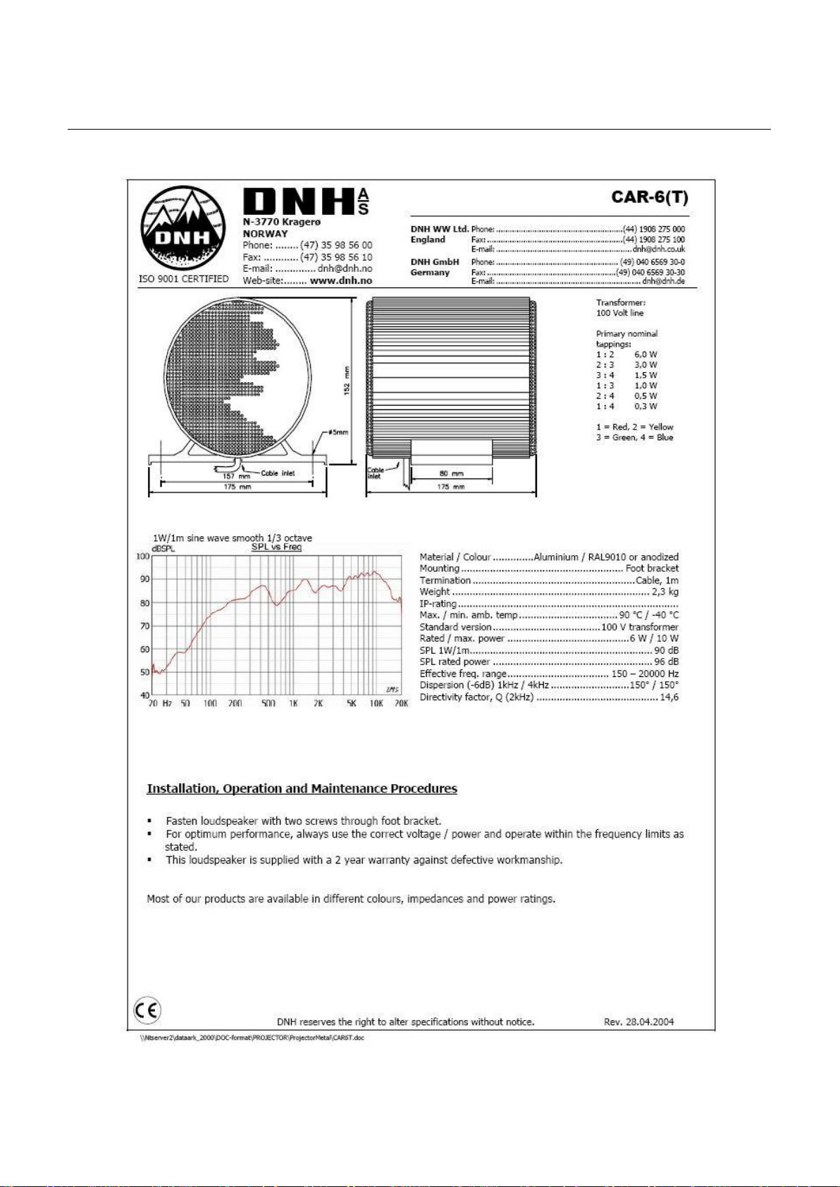
DNH CAR6T:
Handbook page
26 of 89
Doc.No.: 03118-000-IS
Fig. 2.1
Page 5 of 12
 Loading...