


Z-101 A/S/AS
USER MANUAL

Thank you for purchasing our product. Our systems have all been
designed and tested to be compatible with the earliest to latest
vehicles available throughout the world. Our primary goal was to
provide a reliable and stable product. Our secondary goal was to
ensure that our systems are easy to install. Our final goal was to
provide features that would benefit the user and installer. We are
confident that our products will meet and exceed your expectations.
We are constantly working to research, design, and build next
generation products. We would not expect anything less since we
use our products in our own vehicles.
Statement : This device complies with Part 15 of the FCC Rules.
Operation is subject to the following two conditions:
(1) this device may not cause harmful Interference,
and (2) this device must accept any interference received,
Including interference that may cause undesired operation.
Notice : For intentional radiator shall caution the user that changes or
modifications not expressly approved by the party responsible
for compliance could void the user’s authority to operate the
equipment
The use of a permanently attached antenna or of an antenna that user a
unique coupling to the intentional radiator shall be considered sufficient to
comply with the provisions of this section.
The manufacturer may design the unit so that broken antenna can be
replaced by the user, but the use of a standard antenna jack or electrical
connector is prohibited.
NOTES:

NOTES:
CAUTION!
PLEASE READ CAREFULLY
The user and installer should completely read the User Manual,
Installation Manual, and the vehicle’s manual completely before
installing and operating this system. Not reading the manuals
completely may result in injury or damage to the user(s), installer(s),
and/or the vehicle. Installation and use of this system is
acknowledgment that the user and installer have fully read the
manuals and indemnify Zenesis Alarms from any injuries or damages
resulting from wrong use of our system. Please take the following
precautions.
1. When using remote start, place the gear in Park(P)
(automatic transmission) or Neutral (manual transmission)
and set the parking brake (emergency brake)
2. The transmission (Tx) and reception (Rx) distance will vary
from interference from other radio signals.
3. If any defects are discovered, do not open or attempt to
repair the system. Ask the installer for assistance.
4. Zenesis Alarms will not be responsible for any theft and/or
damages to your vehicle.
5. The installer of this system will be responsible for any injuries
and/or damages resulting from incorrect installation.
6. The user of this system will be responsible for any injuries
and/or damages resulting from misuse.

CONTENTS
1. Introduction
1.1 System Contents
1.2 Remote Control Button Layout
1.3 Remote Control Battery Replacement
1.4 Remote Control Button Introduction (Primary/Secondary)
2. Primary Features
2.1 Door Lock (Arm—101 A/AS Only)
2.2 Door Unlock (Disarm—101 A/AS Only)
2.3 Arm / Disarm Status (101 A/AS Only)
2.4 Vehicle Status
2.5 Panic (101 A/AS Only)
2.6 Remote Start
2.7 Trunk Release
2.8 Valet Mode
2.9 Remote Control Button Hold
3. Secondary Features
3.1 User Programmable Options
3.2 Remote Control Registration
3.3 Remote Start Reservation
3.4 Temperature Status
3.5 Paging (101 A/AS Only)
3.6 Remote Control Beep Mute
3.7 Siren Mute (101 A/AS Only)
3.8 Passive Lock (Arm—101 A/AS Only)
3.9 Safety Relock (Rearm—101 A/AS Only)
3.10 Ignition Lock
3.11 Cold Start Timer
3.12 Turbo Timer
3.13 Convenience Run
3.14 Aux Outputs
3.15 Shock Sensor (101 A/AS Only)
3.16 Shock Sensor Sensitivity (101 A/AS Only)
3.16 Shock Sensor ON/OFF (101 A/AS Only)
3.17 Z-PASS TOUCH
6. Warranty Card
6
7
8
9
13
14
14
15
15
15
16
16
17
19
21
21
22
22
22
23
23
24
24
25
28
29
30
31
31
32
32
33
WARRANTY CARD
Use this warranty card for your records. Please go to www.zenesis
alarms/warranty to fill out the warranty details. Visit the link above
for specific warranty terms and conditions.
Model Number
Owner’s Name
Owner’s Address
Owner’s Phone
Date of Purchase
Date of Install
Retailer Name
Retailer Address
Retailer Phone
Installer Name
Installer Address
Installer Phone

3.16 SHOCK SENSOR ON/OFF
The Shock Sensor can be turned ON or OFF via the remote control.
To turn ON or OFF the shock sensor, follow the Button Sequence: Hold Brake
Pedal and than press Function Button 3 times and than press Unlock Button once.
Do the same procedure again to toggle between ON and OFF.
3.17 Z-PASS TOUCH
The system can be armed or disarmed by “touching” the Z-Pass Touch with a
PIN of 4 - 10 digits.
1. PIN Registration
a. Turn Key to ON position (Engine OFF)
b. Press ENTER until ALL OUTER LED’s light up.
c. Enter 4 - 10 digit PIN. In order to toggle between “1 - 5” and “6 - 0”,
press “SHIFT”.
d. Once all of the numbers are entered, press ENTER until all LED’s
blink 3 times.
2. System Arm/Disarm
a. Press ENTER until ALL LED’s blink 1 time.
b. Enter 4 - 10 digit PIN.
c. Press ENTER until ALL LED’s blink 4 times.
d. System will Arm or Disarm accordingly.
3. Driver Call
a. Press DRIVER CALL 3 times while the system is in armed mode.
b. All LED’s will blink quickly and 2 siren chirp / light flash will occur.
Driver call will be sent to the 2-way remote control.
4. Discrete mode
- Hold driver call button until outer LED’s blink once.
- To turn OFF discrete mode, hold down driver call button until outer
LED’s blink twice. Discrete mode can be done in armed or disarmed
mode.
1. INTRODUCTION
1.1 System Contents
1.2 Remote Control Button Layout
1.3 Remote Control Battery Replacement
1.4 Remote Control Button Introduction
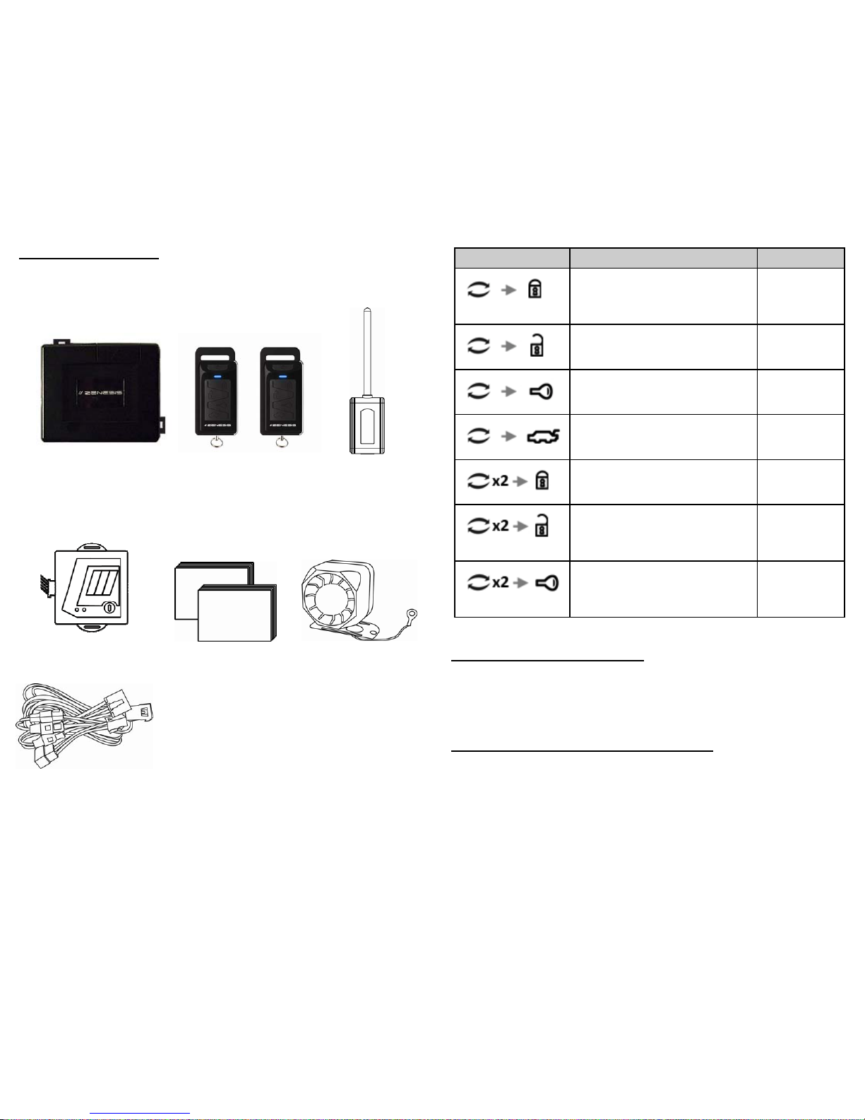
1.1 System Contents
Main Control Module
Remote Control x 2
1 x 2-way & 1 x 1-way
Antenna Module
Shock Sensor
Manuals
Siren
Wiring Harnesses
3.15 Shock Sensor (101 A/AS)
The dual stage shock sensor can detect 2 types of shock: light and hard. Light
shocks will result in siren chirps and parking light flashes as a warning. Hard
shocks will result in the system being triggered. Sustained light shocks will also
trigger the system. If paging is on, the remote control will alert the user to the
triggering of the system.
3.16 Shock Sensor Sensitivity (101 A/AS)
The sensitivity of the shock sensor can be controlled by turning a dial on the
shock sensor module. Turn the dial according to the amount of sensitivity that is
desired. Keep in mind that turning the sensitivity to its maximum can result in
false alarms.
Button(s) Duration Description
Press and release Function Button
→ Press and release Lock Button
Aux 1
Press and release Function Button 0
→ Press and release Unlock Button
Aux 2
Press and release Function Button
→ Press and release Remote Start
Button
Aux 3
Press and release Function Button
→ Press and release Trunk Button
Aux 4
Press and release Function Button
twice → Press and release Lock
Button
Aux 5
Press and release Function Button
twice → Press and release Unlock
Button
Aux 6
Press and release Function Button
twice → Press and release Remote
Start Button
Aux 7
 Loading...