


ZENER VARIDRIVE SOLUTIONS
ZENER 8000 ECODRIVE®
Solar VSD Installation Manual - Supplement
Firmware Revision: V5.2.9
Document: IM00130 Rev J
Printed: 20/07/2018 3:59 PM

ZENER VARIDRIVE SOLUTIONS ZENER ECODRIVE® 8000
Support Links:
ECODRIVE Support Page: www.zener.com.au/support-8e
ZENER 8000 Reference manual: www.zener.com.au/images/im00140.pdf
Document: IM00140
ZENER 8000 Installation Manual: www.zener.com.au/images/im00124.pdf
Document: IM00124
ECODRIVE Supplement manual: www.zener.com.au/images/im00130.pdf
(This manual) Document: IM00130
.php
ECODRIVE Blocking Diodes:
Document: IM00156
ECODRIVE Solar Connectors:
Document: IM00157
If the above cannot be accessed or found please contact ZENER VARIDRIVE:
Phone: 1300 4 ZENER (1300 493 637) Email: sales@zener.net
IM00130 Page | 1 20/07/2018 3:59 PM
www.zener.com.au/images/im00156.pdf
www.zener.com.au/images/im00157.pdf

ZENER VARIDRIVE SOLUTIONS ZENER ECODRIVE® 8000
CONTENTS
Section:
Safety / Warnings 3
Glossary (Terms & Abbreviations) 7
Introduction 8
Standard Applications
Tank Fill 8
Pressure Control 9
Technical Specifications & Ratings 10
Solar Array & PV Selection 12
Installation & Wiring 13
Input Wiring – PV 14
Auxiliary AC Power Supply 15
Motor Wiring 17
Earthing 18
Lightning Protection 18
Output Filters 18
Control Wiring – Tank Fill 19
Control Wiring – Pressure Control 20
Keypad Operation 21
Solar Mode & Parameters 23
Preparation & Preliminary Checks 25
Irradiance Sensor 26
Additional Settings 31
Idle Mode 46
Tank Fill by Pressure 47
Quick Setup Guides:
1 Tank Fill (Tank solar and tank solar AC) 31
2 Pressure Control (Pressure solar and Pressure solar AC) 36
This manual is a simplified guide for the ZENER ECODRIVE 8000 firmware revision V5-2-7.
For full details on parameters & programmable functions refer to the ZENER 8000 Reference manual IM00140.
For details on AC Wiring & circuit protection refer to the ZENER 8000 installation manual IM00124.
IM00130 Page | 2 20/07/2018 3:59 PM
ZENER VARIDRIVE SOLUTIONS ZENER ECODRIVE® 8000
WARNING:
result in damage to the equipment, personal injury or death.
ELECTRICAL WARNING:
warning could result in electrocution.
SAFETY & GENERAL WARNINGS
Read and follow all instructions carefully!!
This chapter contains safety instructions that must be followed when installing, operating and servicing the ZENER ECODRIVE
8000. Non-compliance may result in damage to the ECODRIVE, the motor or other equipment being driven. Non-compliance
may also result in physical injury or death to personnel, livestock or wildlife.
Before installing, commissioning or operating this equipment read the safety instructions in the ZENER 8000 installation manual
IM00124.
All reference to ‘Equipment’ within this chapter refers to the ECODRIVE 8000.
Explanation of symbols
Indicates a condition or practice that, if the warning is not strictly observed, could
This symbol is used to highlight an electrical hazard. Failure to strictly observe the
General
The information and warnings provided consider normal operation and fault situations in an installation where any fault
is promptly repaired (or the equipment isolated from all power sources) so as to avoid the possibility of a second fault
occurring that may result in a hazardous situation.
Read all operating & installation instructions before installing, operating or servicing the equipment. This equipment
must be applied and installed by a suitably qualified and experienced tradesperson in accordance with its manual, good
engineering practice and all local rules and regulations.
There are hazardous voltages inside the ECODRIVE whenever it is connected to an electrical supply and for some time
afterwards. Before touching anything inside the ECODRIVE enclosure or other equipment connected to the ECODRIVE
terminals, disconnect all sources of electrical power, wait at least 11 minutes for capacitors within the ECODRIVE to
discharge to less than 50VDC and then ensure, by measurement, that there is no hazardous AC or DC voltage present at
any terminal.
Note: Auxiliary circuits that are wired into the
Multimeter which is rated to measure 1000Vdc and 600Vac.
Do not work on the ECODRIVE, Photovoltaic Cells, Aux Power sources or motor or associated cables whenever the
ECODRIVE is connected to any power source or Photovoltaic generator, even during times of low intensity or no sunlight.
Always switch off or isolate all power sources and never touch the input side of the isolation switch that has high DC
voltage.
The ECODRIVE contains high energy circuits that may be hazardous. Do not operate the ECODRIVE with the door open or
any part of the enclosure removed.
ECODRIVE enclosure may be powered from other external sources. Use a
IM00130 Page | 3 20/07/2018 3:59 PM

ZENER VARIDRIVE SOLUTIONS ZENER ECODRIVE® 8000
Do not touch the terminals of the equipment or any associated motor wiring when the equipment is energised, even if
motor is stopped. Electric shock may result.
In Auxiliary Power (Dual) Supply applications where the ECODRIVE is supplied from AC power, the photovoltaic
conductors must be treated as being live parts.
Do not modify this equipment electrically, mechanically or otherwise. Modification may create safety hazards as well as
resulting in non-compliance to required standards or approvals.
Ensure the Photovoltaic array maximum open circuit voltage at the expected minimum temperature does not exceed
800Vdc for an 8Exxx or 400Vdc for an 8ELxxx Type ECODRIVE.
Where the ECODRIVE is a component of another product, it is the responsibility of the purchaser to ensure their final
product meets all necessary safety, EMC, regulatory, operational and other requirements for that product. The
requirements for the purchaser’s final product may be substantially different to the requirements for standalone VSD’s or
equipment.
Installation:
The wiring & connection of the ECODRIVE, the motor, photovoltaic modules and other associated equipment must be
carried out by qualified personnel only and installed in a manner which complies with all appropriate standards and
regulations.
Mount the equipment on a vertical, flat, incombustible surface such as metal or masonry. Do not place combustible or
flammable material near the equipment. The equipment must be mounted vertical. Failure to observe these precautions
may create a fire hazard.
Do not install this equipment in locations where mechanical damage to the enclosure is possible. In particular consider
vehicles, vandalism and attack by insects or animals. The equipment may require additional consideration to prevent
unauthorised access.
The ECODRIVE must be mounted away from direct sunlight and any source of heat. If installed in another enclosure,
adequate ventilation must be provided and the resulting temperature rise in the enclosure allowed for. The ambient
temperature of the equipment must be below maximum rated operating temperature.
Attention is drawn to the potential for condensation in vulnerable environments. Additional precautions may be
required.
The installation location and environment should provide for safe access and working conditions for service personnel.
Do not mount the ECODRIVE in “confined spaces”
Do not drill holes in the enclosure except in the gland plate. Remove the gland plate before drilling cable holes.
Do not allow metal shavings or any other conductive material to enter the enclosure or damage may result.
The ECODRIVE is not a Grid Interactive Inverter and does not have integral earth leakage protection or residual current
monitoring functions.
Functional earthing of any of the conductors on the DC side is not permitted. This is a transformer less (non-isolated)
system.
1
.
1.
Confined spaces are generally defined in Occupational Health and Safety (OH&S) regulations to mean spaces where
special precautions are necessary to ensure a safe breathing atmosphere, or there is limited access for escape/rescue in
case of emergency.
IM00130 Page | 4 20/07/2018 3:59 PM

ZENER VARIDRIVE SOLUTIONS ZENER ECODRIVE® 8000
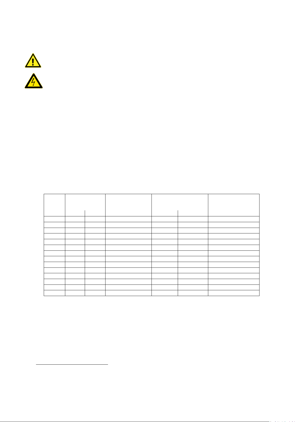
Cross-sectional area of Supply conductors
Minimum cross-sectional area of corresponding
Sp (mm2)
S ≤ 4
35 < S
4
S/2
The values in this table are valid only if the protective earthing conductor is made of the same metal as the phase
conductors.
The ECODRIVE does not have integral disconnect devices and these must be provided externally for each supply source.
The disconnector in the DC supply circuit must be rated to switch the whole photovoltaic array current and rated to
switch the array maximum open circuit DC voltage at the expected minimum temperature. A pole in each polarity is
required.
In Dual Supply applications where the ECODRIVE is supplied from AC power and DC power from a photovoltaic generator,
a disconnect contactor must be fitted in series with the AC input of the ECODRIVE. Control for the disconnect contactor
coil must be powered by a transformer powered from 2 phases of the AC Power Supply.
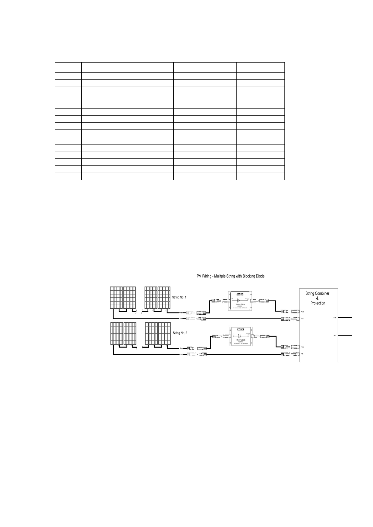
In Dual Supply applications where the ECODRIVE is supplied from AC power and DC power from a photovoltaic generator,
a 1600V Blocking Diode must be fitted in series with either the Positive or Negative conductor in every array string.
to wiring/application section for more details.
This equipment is intended for use only in fixed wiring applications. It is not intended for use on a flexible supply cable
without the use of a connection with an industrial connector according to IEC 60309 and a minimum protective
Earthing conductor cross-section of 2.5mm
provided.
Due to
high system leakage capacitances, integral EMC filtering and the dynamic system voltage changes, this equipment
is not compatible for use with residual current devices for protection against electric shock.
If a residual current device used for the protection against a fire hazard is required, it must be fitted on the AC input of
the ECODRIVE when operating from an earth referenced AC supply. A type A or type B device can be used if the AC supply
is single phase. The residual current device must be type B when the AC supply is three phase.
A separate residual current device or monitor is required if protection against a fire hazard is required when the
ECODRIVE is disconnected from the AC supply and powered from the photovoltaic generator.
Install emergency stop circuitry that removes power from the equipment and does not depend on any feature of the
product for proper and safe operation.
2
as part of a multi-conductor power cable. Adequate strain relief shall be
Refer
Earthing:
It is the installer’s responsibility to assure that all earthing connections are properly made and meet all local rules and
regulations.
All exposed conductive parts of the ECODDRIVE, motor and solar panels must be earthed to ensure personal safety in all
circumstances.
A protective earthing conductor shall be connected at all times when power is supplied to the ECODDRIVE.
Unless local wiring regulations state otherwise, the protective earthing conductor cross-sectional area shall be
determined from the following table:
S (mm2)
4 ≤ S ≤ 16
16 < S ≤ 35
IM00130 Page | 5 20/07/2018 3:59 PM
protective earthing conductor
S
16
ZENER VARIDRIVE SOLUTIONS ZENER ECODRIVE® 8000
ECODDRIVE’s touch current is greater than 3.5 mA ac. The standard IEC 62109-1 states that, one or more of the
The
following measures shall be applied.
a) Permanently connected wiring, and:
• a cross-section of the protective earthing conductor of at least 10 mm
or
• automatic disconnection of the supply in case of discontinuity of the protective earthing conductor;
or
• Wiring a second protective earthing conductor of the same cross-sectional area as the original protective
earthing conductor to a second protective earthing conductor terminal.
or
b) connection with an industrial connector according to IEC 60309 and a minimum protective
earthing conductor cross-section of 2.5 mm
Adequate strain relief shall be provided.
2
as part of a multi-conductor power cable.
2
Cu or 16 mm2 Al,
Operation
Power should only be applied to the ECODRIVE after:
- all wiring has been checked including earthing.
- all wiring including the solar array has been insulation tested to verify that there are no earth faults present.
- All components of the system have been checked to be suitably rated and connected as per manufacturer’s
specifications and recommendations.
Ensure you understand how to operate the equipment before attempting to run the motor/pump to test direction. Use
the set-up guide provided to setup / commission the equipment or consult Zener for assistance.
If you are require clarification or more information on any of the above
please contact Zener.
Phone: 1300 493 637
or
Email: sales@zener.net
IM00130 Page | 6 20/07/2018 3:59 PM

ZENER VARIDRIVE SOLUTIONS ZENER ECODRIVE® 8000
AUX Power Supply
Blocking Diode
ECODRIVE
Grid Interactive Inverter
kW
MPPT
NOCT
Normal Operating Cell Temperature. Measurements are provided by PV manufacturers to
Mounting = open back side.
PID
A type of automatic controller that seeks to drive a measured value (such as pressure) to a
functions.
Photovoltaic cell / PV
PV Array or Solar Array
PV String
STC
Vmax.
Voc
Open circuit voltage. Voltage from the Photovoltaic module or array without no load
connected.
GLOSSARY of Terms & Abbreviations
This manual uses the following terms and abbreviations:
Term/Abbreviation Explanation
This refers to a secondary or backup supply that can be connected to the ECODRIVE during
times of Low solar intensity or no sunlight.
This is a semiconductor device that is connected in each string that allows current to flow in
one direction only. It prevents current flow from the ECODRIVE to the PV modules.
This is a ZENER product that converts a DC supply (and AUX AC supply) to control a 3phase
induction motor dependent upon the power extracted from an array of solar panels. A
registered trademark of Zener Electric Pty Ltd.
Is a device that converts direct current (DC) electricity into alternating current (AC) with an
ability to synchronize and be fed onto the public utility grid.
Kilowatts. A measurement of power, that can refer to electrical or mechanical power.
Maximum Power Point Tracking. The control or algorithm to extract the maximum available
power from the PV array under all conditions.
provide a more practical/in field ratings. Defined as the temperature reached by open
circuited cells in a module under the conditions as listed below:
Irradiance on cell surface = 800 W/m2
Air Temperature = 20°C
Wind Velocity = 1 m/s
preset value by means of a control effort determined by proportional, integral and derivative
This refers to the device used to convert sunlight directly into electricity by the photovoltaic
effect. The output is a DC voltage.
This is a network of solar panels connected in a ‘series & parallel’ arrangement to achieve
the required voltage and current (Power)
This refers to the series connected PV modules. The number of PV modules in a string will
determine the system voltage. The strings of equal quantity of modules are then connected
in parallel to achieve the current & power required.
Standard Test Conditions. Stands for standard test conditions and is the major solar panel
output performance testing condition used by most manufacturing and testing bodies. The
test conditions are defined as – irradiation: 1000W/m2, temperature: 25°C, AM:1.5
Voltage at maximum power. Voltage measured at output of a Photovoltaic module or array,
with a load connected under maximum power conditions.
IM00130 Page | 7 20/07/2018 3:59 PM

ZENER VARIDRIVE SOLUTIONS ZENER ECODRIVE® 8000
INTRODUCTION
The ZENER ECODRIVE 8000 is a variable speed drive and as
applied to solar power systems is an ‘off the grid’ system that
is also able to import power from the grid. It is designed for
the sole purpose to operate a standard 3 phase induction
motor.
The ECODRIVE is designed to allow the connection of an
Auxiliary AC Power supply in the absence of sufficient
sunlight. This could be from the GRID or a generator.
The ECODRIVE provides Maximum Power Point Tracking (MPPT), a control algorithm that achieves the maximum power from
the PV array under all conditions. The ECODRIVE also includes Zener’s sophisticated motor control algorithm designed to
achieve maximum energy efficiency. The ECODRIVE is versatile, offering enormous flexibility for system integrators or OEMs
with its internal logic functions, programmable I/O and ability to communicate with other equipment.
Although the ECODRIVE is an ideal pumping solution it can be used on other applications or load types that operate a 3 phase
motor.
Features & Benefits:
• Operates a standard 3 phase motor
• Maximum Power Point Tracking - MPPT
• Fast start response speed
• Automatic control of Auxiliary power supply
• Input for & monitoring of radiance sensor
• Reduced motor starting currents
• Soft start & stop on pump
• Easy parameter access and adjustment
• DC solar input and AC input
• Range of digital & analogue inputs & outputs
• Robust IP66 Enclosure
• Stainless Steel option Available
• Robust & durable metallic enclosure for protection
against mechanical damage and damage from harsh
environmental conditions.
• Protection level of IP66
• Plain English display
• High ambient temperature rating available
• Advanced & customised pump protection
• Easily customised systems
Applications & Application Menus:
There are many modes of operation that can be customised depending on your individual requirements. To simplify installation
& setup, Zener has selected 2 common modes of operation in which an ‘Application Menu’ has been developed for each. These
are further detailed within this manual.
Application menu Choices are:
1. Tank Fill Operation ‘Tank Solar’ for operation on solar only to fill a tank using a float switch to
control the pump.
‘Tank Solar AC’ for operation on solar to fill a tank using a float switch to control
the pump. An auxiliary supply is used to operate the pump when insufficient
solar energy.
2. Pressure Control Operation ‘Pressure Solar’ for operation on solar only to control a pump to deliver
constant pressure.
‘Pressure Solar AC’ for operation on solar only to control a pump to deliver
constant pressure. An auxiliary supply is used to operate the pump when
insufficient solar energy.
The Application Menu aims to simplify the setup & programming process by providing a customised menu with only the
parameters required. Other parameters are assessable in other menus. Please contact Zener for assistance with other types of
applications and/or the development of a customised Application menu or refer to the ZENER 8000 manual.
IM00130 Page | 8 20/07/2018 3:59 PM

ZENER VARIDRIVE SOLUTIONS ZENER ECODRIVE® 8000
The ECODRIVE is configured to pump and fill a tank or vessel
Bore/Well Level Protection:
Diagram 4a: Simple Tank Fill
STANDARD APPLICATIONS
Application – Tank Fill
when the level is not full and there is sufficient solar energy
available. An AC supply can also be used to pump when
insufficient solar available.
A single float switch located in the tank closes a contact when
the water in the tank falls. When this contact closes and there
is sufficient solar energy (ie.‘SOLAR GOOD’), the ECODRIVE
will start to pump. The ECODRIVE will run at a ‘preset’ speed
or alternate speed reference. When the water level increases
and the float switch contact is open for a preset (‘qualifying
time’) time the ECODRIVE will stop the pump. The float needs
to be installed below the high water level with an allowance
for pumping for the duration of the qualifying time. This
approach means the tank is always full, not waiting for a low
level switch to turn on the pump when there may be no solar
energy available.
If the solar energy is not sufficient to maintain the desired
operating speed, the speed is reduced resulting in a lower
flow rate. When the solar energy or the speed reaches the
minimum level (ie. ‘SOLAR LO’) for a period of time
(‘qualifying time’) the ECODRIVE will switch off. When there is
insufficient voltage from the solar array the ECODRIVE will
completely shut down.
When sufficient solar energy returns the ECODRIVE will repower and can automatically restart the pump.
An optional bore level protection is also available to prevent dry running the pump. When a low level is detected the ECODRIVE
will stop the pump and restart after an adjustable time period.
Irradiance Sensor:
When operating from Solar only, an irradiance sensor is optional. Without the irradiance sensor the ECODRIVE monitors the DC
bus voltage and adjusts the motor speed accordingly. When an Auxiliary AC supply is used an irradiance sensor is required.
Auxiliary AC power Supply:
During periods of ‘Lo Solar’ or no sunlight, the ECODRIVE can provide an output to connect the GRID or generator supply to
continue to operate. This may be finely tuned to achieve no interruption during changeover as the solar is always connected.
Configuration / programming:
To guide you through the setup/programming for this application refer to the following pages:
Supply & Motor Wiring Page 13
Earthing: Page 18
Control wiring: Page 19
Preliminary checks: Page 25
Programming /setup: Solar only Solar OR AC Aux Supply Page 31
IM00130 Page | 8 20/07/2018 3:59 PM

ZENER VARIDRIVE SOLUTIONS ZENER ECODRIVE® 8000
The ECODRIVE is configured to provide a constant
pressure using an integral PID controller. The
24VDC DC loop power supply for a pressure
Bore/Well Level Protection:
Diagram 4b: Simple Pressure Control
Application – Constant Pressure Control
ECODRIVE monitors the pressure and adjusts the
motor/pump speed to achieve the set pressure.
The ECODRIVE will operate the pump at the speed
required to achieve constant pressure. If the solar
energy is not sufficient to maintain this pressure the
system can be configured to operate at a lower
pressure or switch off.
When the solar energy or the speed reaches a
minimum level (ie. ‘SOLAR LO’) for a preset time
(‘qualifying time’) the ECODRIVE will switch off. When
there is insufficient voltage from the solar array the
ECODRIVE will completely shut down.
When there is sufficient solar energy the ECODRIVE will
re-power and can be configured to automatically
restart the pump.
The ECODRIVE with an option board fitted provides a
transducer.
Additional protection for bore level, no flow or external
over pressure can be included.
An optional bore level protection is also available to prevent dry running the pump. When a low level is detected the
ECODRIVE will stop the pump and restart after an adjustable time period.
Irradiance Sensor:
When operating from Solar only, an irradiance sensor is optional. Without an irradiance sensor the ECODRIVE monitors the
DC bus voltage and adjusts the motor speed accordingly. In a dual supply arrangement and an AC supply is used, an
irradiance sensor is required.
Dual Supply / AC Power:
During periods of ‘Lo Solar’ or no sunlight, the ECODRIVE can provide an output to connect the GRID or generator supply to
continue to operate. This may be finely tuned to achieve no interruption during changeover as the solar is always
connected.
Configuration / programming:
To guide you through the setup/programming for this application refer to the following pages:
Supply & Motor Wiring Page 13
Earthing: Page 18
Control wiring: Page 19
Preliminary checks: Page 25
Programming /setup: Solar only Solar OR AC Aux Supply Page 36
IM00130 Page | 9 20/07/2018 3:59 PM
ZENER VARIDRIVE SOLUTIONS ZENER ECODRIVE® 8000
Continuous
(Amps)
Nominal Motor
40°C / 50°C
PV DC Input current
Auxiliary AC Input
(A RMS max.)
40°C
50°C
Continuous
Intermittent
8E001XX
2.0
2.0
0.75 / 0.75
2.4
3.2
1.9
8E003XX
3.6
3.0
1.5 / 1.1
4.4
5.7
5.2
8E005XX
5.0
4.1
2.2 / 1.5
6.1
7.9
6.9
8E007XX
7.2
6.0
3.0 / 2.2
8.7
11.4
9.7
8E011XX
10.8
9.0
5.5 / 4.0
13.1
17.1
13.6
8E016XX
16.0
13.2
7.5 / 5.5
18.1
23.5
17.8
8E023XX
22.5
18.8
11.0 / 7.5
27.3
35.5
27.7
8E030XX
30.1
25.0
15.0 / 11.0
36.6
47.5
35.4
8E040XX
40.3
33.8
22.0 / 15.0
49.0
63.7
44.4
8E057XX
57.0
46.0
30.0 / 22.0
69.2
84.8
64.2
8E082XX
82.0
69.1
45.0 / 37.0
100
125
89.1
8E109XX
109.0
91.3
55.0 / 45.0
132
166
123
8E140XX
140.0
118.9
75.0 / 55.0
170
213
153
8E170XX
170.0
141.3
90.0 / 75.0
207
227
183
TECHNICAL SPECIFICATION & RATINGS
Ensure to select the appropriate controller model to according to the PV modules, motor and load requirements.
Ensure to number of PV Modules per string do not exceed the ECODRIVE’s maximum voltage rating under all conditions.
Electrical Specifications:
The following applies to the 480V model (suitable for 3 Phase motors)
PV DC Input Voltage: Maximum 800VDC
(Must ensure that Voc at lowest operating temperature does not exceed this voltage)
Auxiliary AC Input Voltage: 380 - 480Vac 3 Phase or 1 phase 2 (-15%, +10%)
Nominal MPP Voltage: 407-727VDC
Output Voltage: 0-480VAC 3 Phase 3
Output Frequency: 0-200Hz (maximum speed subject to DC bus voltage & solar energy available)
V/Hz: Adjustable
For all other voltages contact Zener.
Input / Output Current:
Model
Contact Zener for sizes above this for a customised solution, up to 490Amps
Refer to instruction manual IM00124 for more details on ratings, in particular for standard 3phase AC operation and
recommended circuit protection.
Output Current
Nameplate
Power (kW)4
(A RMS max.)
Current with DC bus
Choke fitted
2
For single phase operation a DC bus choke must be fitted and a derating applied. Contact Zener for assistance.
3
The output voltage cannot be higher than the AC input voltage or 70% of the DC input.
4
Always select the ECODRIVE on motor full load current not power.
IM00130 Page | 10 20/07/2018 3:59 PM
ZENER VARIDRIVE SOLUTIONS ZENER ECODRIVE® 8000
Model
Chassis ID
IP30
IP66
S/Steel IP66
8E001XX
CHA
-
310h 190w 236d
310h 190w 236d
8E003XX
CHA
-
310h 190w 236d
310h 190w 236d
8E005XX
CHA
-
310h 190w 236d
310h 190w 236d
8E007XX
CHA
-
310h 190w 236d
310h 190w 236d
8E011XX
CHA
-
310h 190w 236d
310h 190w 236d
8E016XX
CHA
-
310h 190w 236d
310h 190w 236d
8E023XX
CHB
459h 234w 243d
459h 234w 243d
459h 234w 243d
8E030XX
CHB
459h 234w 243d
459h 234w 243d
459h 234w 243d
8E040XX
CHB
459h 234w 243d
459h 234w 243d
459h 234w 243d
8E057XX
CHB
459h 234w 243d
459h 234w 243d
459h 234w 243d
8E082XX
CHC
715h 470w 298d
715h 470w 298d
715h 470w 298d
8E109XX
CHC
715h 470w 298d
715h 470w 298d
715h 470w 298d
8E140XX
CHC
715h 470w 298d
715h 470w 298d
-
8E170XX
CHC
715h 470w 298d
(IP54) 715h 470w 298d
-
8E170XX
CHC+
-
(IP66) 715h 670w 298d
-
Chassis Dimensions:
All dimensions in mm. Contact Zener for larger sizes.
Blocking Diode :
A blocking diode is required whenever an Auxiliary AC Power Supply is used. With standalone solar installations, blocking
diodes are optional but recommended with multi-string installations to ensure maximum efficiency where partial shading
of the PV modules may occur.
Continuous Current Rating: 14Amps @ 50°C
Maximum panel/String Isc @ STC: 10Amps
Voltage Rating: 1600V
Part Number: AQ08300
Instruction sheet: IM00156
Other sizes available on request.
Options :
DC Bus Choke Fitted within the ECODRIVE’s IP30 or IP66 enclosure. A DC bus choke is
mandatory for all applications using an Auxiliary AC power Supply.
Additional Extended Features Option Board AQ/AF08001 (1x Option Board included as standard)
Relay Option Board AQ/AF08202: 2x Programmable Relays with Changeover contacts.
Irradiance Sensor AQ/AF08304
Ethernet Modbus TCP Communications AQ/AF08204
Remote IP66 Console AQ/F08217 Remote Console /Interface kit - CHA/B
AQ/F08218 Remote Console /Interface kit - CHC
AQ/F08219 Remote Console /Interface kit - CHD
Output Filters: Filters for submersible pumps, long cable runs or no screen cables
AC ‘Step up/step down’ Blending Transformer: Contact Zener for selection
IM00130 Page | 11 20/07/2018 3:59 PM

ZENER VARIDRIVE SOLUTIONS ZENER ECODRIVE® 8000
Graph 5a. PV voltage & current at different solar intensity
THE SOLAR ARRAY & PV SELECTION:
The Solar Array consists of a number of Photovoltaic (PV) modules
connected in a series & parallel combination to achieve a certain
voltage, current and power. It is important to select these carefully as
the PV modules are a major cost of an installation and can be very
expensive to rectify. Incorrect selection may result in damage to the
equipment or not provide sufficient energy to operate the motor and
the load it is driving. An array would normally consist of a number of
PV modules in series, known as a ‘string’. Strings of PV modules are
then connected in parallel to achieve the required current (Amps) to
form an ‘Array’.
Voltage:
The quantity of series connected PV modules determine the DC
voltage of the Solar Array which determines the output motor
voltage. This can have a direct impact on the maximum motor speed
achievable. If rated speed of the pump is not required then the Vmpp
of the system can also be reduced. In this case the power
requirement is also reduced.
There are two variables that are critical for system operation:
TOTAL Voc = The sum of the ‘Open circuit voltages’ of the PV
modules connected in series. The total open circuit voltage must
be <800Vdc under all possible conditions.
TOTAL Vmpp = The sum of the ‘voltage at maximum power’ of
the PV modules connected in series. This voltage under max load
conditions is the voltage level for Maximum power point tracking.
Current & Power:
The quantity of ‘Strings’ connected in parallel will impact the current and power available to operate the pump. If the current
required to pump is higher than what can be delivered by the solar array, the pump speed will be reduced. Graph 5a illustrates
the reduced current & power based on the instantaneous solar intensity.
The incorrect amount of PV modules or an incorrectly installed array may result in the following:
• Pump will not operate at the required speed.
• Pump will not operate at the desired solar intensity (such as filtered sunlight, cloudy periods).
• Pump will not operate for the desired period per day.
• Damage to the equipment.
The PV modules and solar array should be selected by an experienced and accredited person.
The PV modules must be installed by a qualified and experienced person to ensure all equipment is installed to best
practice, local codes and regulations.
Unsure about your Solar Array configuration?
For guidance with selecting the correct Solar Array configuration complete the ‘ ECODRIVE Checklist’ available on our website
and email to us.
IM00130 Page | 12 20/07/2018 3:59 PM
http://zener.com.au/images/solar_ecodrive_checklist.pdf

ZENER VARIDRIVE SOLUTIONS ZENER ECODRIVE® 8000
INSTALLATION & WIRING
REMINDER: This equipment must be installed by qualified electrical personnel with the appropriate accreditations. The
equipment operates from 800VDC which requires special consideration when installing and operating. Refer to all warnings
located at the front of this manual. This manual should be read in conjunction with the ZENER 8000 instruction manual and
all applicable standards and regulations.
PLEASE READ ALL WARNINGS IN SECTION 1 BEFORE PROCEEDING.
Section 1 contains critical safety warnings that relate to the installation of the equipment in particular earthing
requirements.
Mounting location
In general the ECODRIVE should be mounted as close to the motor as practical, consistent with other requirements. This is
not an absolute requirement, but does provide some advantages.
The ECODRIVE must be mounted to a wall or internal mounting plate of an enclosure. Ensure that the full weight of the
ECODRIVE can be supported.
The equipment must be protected from direct sunlight and installed in a location suited to its enclosure type. If installed in an
enclosure, adequate ventilation is required and temperature rise within the enclosure considered.
The ECODRIVE must be mounted with clearance around the vents and the enclosure to allow for sufficient airflow for the
enclosure to dissipate heat. The following clearances should apply.
CHA Allow 50mm above, below and either side of the enclosure
CHB Allow 75mm above, below and either side of the enclosure
CHC Allow 100 above, below and either side of the enclosure
• Do not drill holes in the enclosure except in the gland plate provided.
• Remove the gland plate before drilling holes.
• Do not allow metal shavings or other conductive material to enter the enclosure or damage may result.
• The location & environment should provide for safe access and working conditions for service personnel. Do not
mount the equipment in a ‘Confined Space’
For all other auxiliary equipment such as PV modules, transducers, diodes refer to the manufacturer’s instructions.
5
.
5
Confined spaces are generally defined in occupational health and Safety regulations to mean spaces where special precautions
are necessary to ensure a safe breathing atmosphere, or there is limited access for escape/rescue in case of an emergency.
IM00130 Page | 13 20/07/2018 3:59 PM
 Loading...