


www.Zendit.co
Wireless Key fob, Key pad & Receiver Range
• Instruction Manual •
Covering the WIR300, WIR400 and WIR500 series
Ultra compact design to
t in other enclosures
(Alarm panel etc.)
1x Voltage Free relay
output (NO + NC)
12V DC Input
12V DC Input
1, 2, 3 and 4
button options
Button
Protector
Battery
Operated
50m transmission
range
Wall holder
available
Black and
white options
Belt clip
available
4 button for testing
or manual control
Tough
metal
case
2 Channel
wireless control
Multiple user
codes
Battery
powered
100m
Transmission
range
Attractive
design
White or
dark grey
nish
Clear hinge
up lid
4x Voltage Free relay
outputs (NO + NC)
Latching / non-latching
user selectable
Compact design
White or black case
Key chain supplied
(Can be removed)
Key Fobs
Micro 1Ch Receiver
4Ch Wireless Receiver
Wireless Access
Key Pad

2
www.Zendit.co
Introduction
The Zendit range of wireless key fobs & key pads is a gift to any CCTV, alarm or access
control engineer thanks to its versatility and wide range of congurations.
Ideal for opening gates, switching lights on, sounding audio devices such as the VoiceO,
this great value range adds lots of functionality to a security or automation system
without a hefty price tag.
The key fobs can be used as a standard fob for up to 4 devices or even wall mounted in a
bracket to serve as a static panic button or controller. Handy belt clips are also available
to carry the fobs on your person within easy reach again as either a panic button or for a
member of sta to gain quick control or access of other equipment.
The entire range includes single or multi (2, 3 or 4) button key fobs in either a white or
black nish with a selection of key-rings and clips, compact wall mount push button key
pads and 1 or 4 channel receivers with control buttons too.
Dual channel key pads are a useful addition to the range allowing a xed access pad to
activate the opening of a door or gate without the risk of personnel losing or forgetting
their keys.

3
www.Zendit.co
Contents
Key Fobs
4
Information / Specication 4
Pairing Key fobs & Receivers 4
Self Learning 5
Replacing A Battery 5
Useful Accessories 5
Key Pads
6
Information / Specication 6
Installation 6
Pairing Key fobs & Receivers 7
Operation 7
Password Management 8
Battery Maintenance 9
1Ch Receiver
10
Information / Specication 10
Installation 10
Connections & Powering 10
Connecting Trigger Devices 11
Latching Modes 11
4Ch Receiver
12
Information / Specication 12
Installation 12
Connections & Powering 13
Connecting Trigger Devices 13
Latching Modes 15
Basic Operation 15

4 www.Zendit.co
Wireless Key Fobs
The Zendit key fobs o er an e ective, low cost method for
wireless control of up to 4 electronic devices.
1, 2, 3 and 4 channel fobs are available in black and white. The
small compact fobs have a working range of up to 50m and a
handy sliding button guard prevents accidental activation.
This section explains the simple steps required for pairing
key fobs to receivers, learning commands, replacing
batteries and operation.
Speci cation
Frequency Range Battery Dimensions
433.92MHz Up to 50m 3V CR2032 65 x 37 x 14.5mm
Pairing Key fobs & Receivers
It’s really easy to pair a key fob with a receiver, just follow
these 2 simple steps:
Step 1
Press the Learn button on the receiver. The LED light on
the front of the unit will turn red.
For the 1Ch WIR401 this is found on the side of the unit.
On the 4Ch WIR404 it is positioned at the top of the PCB.
To gain access you will rst need to remove the cover by
unscrewing the small locking screws on either side of the
unit. The front panel can then slide up and o .
Step 2
Press Button 1 on the key fob Twice. The LED light on the
receiver will ash and then turn o .
Note: When pairing a multi channel key fob all other
channels are learnt automatically after learning
channel 1. Channel 1 activates relay 1, channel 2
activates relay 2 and so on.
WIR401
- 1Ch Rx
Learn
Button
Learn
Button
Key Fob Part Codes:
1ch - WIR301B (Black) WIR301W (White)
2ch - WIR302B (Black) WIR302W (White)
3ch - WIR303B (Black) WIR303W (White)
4ch - WIR304B (Black) WIR304W (White)
WIR404 - 4Ch Rx

5www.Zendit.co
Wireless Key Fobs
Self Learning
The Self Learning function (On the 2, 3 & 4 channel key fobs) allows you to copy
commands from one key fob to another. Self Learning is an easy way to set up multiple
key fobs or add new key fobs without having to go back to the receiver.
To program a key fob using Self Learning follow the 3 steps below:
Replacing A Battery
The key fobs are powered by a CR2032 3V DC battery
which should last for up to 2 years of general use. Don’t
worry, when the battery does run out you won’t need to
pair the key fob again, just replace the battery.
To replace the battery you will rst need to remove the
three small screws from the back of the key fob (shown
right). Remove the back of the housing to reveal the
battery. Slide the battery out of its holding slot and
replace with a new one ensuring the new battery is
installed with the positive side facing up.
Useful Accessories
Wall mount brackets allow key fobs to serve as a static
panic button or controller.
Handy belt clips are also available to carry the fobs on
your person within easy reach again as either a panic
button or for quick control or access of other equipment.
Step 1
On the Existing key fob press
Buttons 1 and 2 together.
Step 2
Now press Button 2.
Step 3
Now on the New key fob
press Button 1 Twice.
Order Codes:
Wall Mount Bracket Black: WIR310B
Wall Mount Bracket White: WIR310W
Belt Clip: WIR311
Screws
Battery

6 www.Zendit.co
Wireless Key Pads
Our dual channel key pads can be used to create a xed
access pad ideal for opening doors and gates eliminating
the risk of losing or forgetting keys.
Relays are activated by entering a numeric password
rather than the press of a single button for a secure
wireless solution.
This section explains the simple steps required for
installation, pairing key pads to receivers, operation,
password management and battery replacement.
Speci cation
Frequency Range Battery Dimensions
433.92MHz Up to 100m 3V CR2450 93 x 73 x 43mm
Installation
As an anti-tamper measure key pads can only be installed
and removed using one of the keys supplied:
Step 1
Insert the key into the lock on the underside of the key
pad. Turn the key clockwise until it clicks and then lift the
front of the key pad o the mounting plate.
Step 2
There are ve mounting indented knock-out holes for
securing the key pad. Either use a hammer and punch
or drill out the holes required. You can choose to use 3
screws in holes 2, 4 & 5 or 4 screws in holes 1, 3, 4 & 5.
Step 3
Mark the screw positions on the mounting surface, drill
the holes and plug with appropriate xings.
Step 4
Screw through the holes in the key pad’s base and into the plugs.
1
Key
1
4
3
5
2
2
Key Pad Part Codes:
Black - WIR305B White - WIR305W

7www.Zendit.co
Wireless Key Pads
Pairing Key pads & Receivers
It’s really easy to pair a key fob with a receiver, just follow
these 2 simple steps:
Step 1
Press the Learn button on the receiver. The LED light will
turn red.
For the 1Ch WIR401 this is found on the side of the unit.
On the 4Ch WIR404 it is positioned at the top of the PCB.
To gain access you will rst need to remove the cover by
unscrewing the small locking screws on either side of the
unit. The front panel can then slide up and o .
Step 2
Enter the password for channel 1 (Default 000000 / 6 Zeros)
and then press Button A Twice on the key pad. The LED
light on the receiver will ash and then turn o .
Note: For changing or resetting passwords see the
Password Management section on page 8.
Operation
To trigger channel 1 simply enter your password and then
press Button A. The top left LED will ash when successful.
Likewise, to trigger channel 2 enter your password and then
press Button B. The top right LED will ash when successful.
Note:
After entering your password you have 4 seconds to
press either Button A or B. If you press Button A or B
after 4 seconds or enter an incorrect password no signal
will be transmitted and you will have to start again.
For extra security you can set diff erent passwords for
channels 1 and 2 as explained on page 8.
WIR401
- 1Ch Rx
Learn
Button
Learn
Button
WIR404 - 4Ch Rx
WIR305W

8 www.Zendit.co
Wireless Key Pads
Password Management
Zendit password controlled key pads provide extra security
as they restrict access and control to chosen personnel.
You can even set di erent passwords for each channel.
The section below has simple steps on changing and
resetting passwords.
Default Password
The default password for both channels is 000000.
Changing The Password For Channel 1
• Hold down Button A until the top left LED lights up.
• Enter current password e.g. 000000 and press Button A.
The second LED will then light up.
•
Enter your new password e.g. 123456 and press Button A.
The third LED will then light up.
• Re-enter your new password e.g. 123456 and press
Button A. The rst three LEDs will then ash to con rm
your new password has been set.
Changing The Password For Channel 2
• Hold down Button B until the top right LED lights up.
• Enter current password e.g. 000000 and press Button B.
The third LED will then light up.
•
Enter your new password e.g. 123456 and press Button B.
The second LED will then light up.
• Re-enter your new password e.g. 123456 and press
Button B. The last three LEDs will then ash to con rm
your new password has been set.

9www.Zendit.co
Wireless Key Pads
Resetting The Password
• Insert the key into the lock on the underside of the key
pad. Turn the key clockwise until it clicks and then lift
the front of the key pad o the mounting plate.
• Press and hold any numeric button so that the second
LED lights up.
• Keep holding the button, with the other hand turn the
battery cover clockwise and remove. Re-insert and turn
anti-clockwise to lock in place. All 4 LEDs will then light
and go out one by one from the right. The password will
now be reset to default 000000.
Battery Maintenance
The key pads are powered by a CR2450 3V DC battery
which should last for up to 2 years of general use. Don’t
worry, when the battery does run out you won’t need to
pair the key pad again, just replace the battery.
Note: To replace the battery you will need to use one of the
keys supplied with the key pad.
Low Battery Indicator
If the battery voltage is lower than 2.4V the two centre LEDs
will light together when pressing any
numeric button
as a
reminder to the user that the battery requires replacement.
Replacing A Battery
• Insert the key into the lock on the underside of the key
pad. Turn the key clockwise until it clicks and then lift
the front of the key pad o the mounting plate.
• Turn the battery cover clockwise and remove.
• Slide the battery out of the holding clips and replace
with a new battery ensuring the negative side of the
battery is left exposed.
• Re-insert and turn anti-clockwise to lock in place.

10 www.Zendit.co
1Ch Wireless Receiver
The compact 1Ch receiver is perfect for smaller systems. For
extra security the WIR401 uses rolling codes which change on
every use, this means they are never duplicated.
Speci cation
Feature Speci cation
Working Voltage 12V DC 30mA
Temperature Range -20ºC ~ +60ºC
Frequency 433.92MHz
Max Stored Transmitters 30
Relay Load Capacity 1A 30V DC
Weight 36g
Dimensions 58 x 34 x 20mm
Installation
To mount the lightweight receiver we recommend a
simple double-sided adhesive foam pad.
Connections & Powering
All connections to the WIR401 are made using the screw
terminals at the bottom of the receiver. This can be done
without opening the case. Removing the front faceplate
exposes the screw terminals and the wires can be inserted
into the holes in the bottom of the case (right top).
There are 5 screw terminals (right bottom). The rst 2 from
the left are for connecting the power. These terminals
are not polarity sensitive so the 12V DC and the Ground
(GND) can be connected to either terminal. The receiver
requires 12V DC power source supplying at least 30mA.
The last 3 terminals are for the relay. From left to right they
are Normally Closed (NC), Common (COM) and Normally
Open (NO). The relay is limited to 30V DC and rated at 1A.
When connecting a trigger device to the receiver you
will also need to set latching mode as explained on the
opposite page.
12V DC
/ GND
NC COMNO
1Ch Receiver Part Code: WIR401

11www.Zendit.co
1Ch Wireless Receiver
Connecting Trigger Devices
The WIR401 can be used
to control various trigger
devices. On the right are
a few examples on how
to wire the most common
trigger devices.
When trigger devices are
connected you will need
to set the latching mode as
explained below.
Latching Modes
The WIR401 has two Latching modes which control how
long the relay is active, Latching and Non-Latching.
Latching acts as an On/Off switch. When the transmitter
is pressed the relay will stay active until the transmitter is
pressed again.
Non-Latching mimics the press of the transmitter and will
only remain active as long as the transmitter is pressed.
(Not compatible with WIR305 key pads)
The Latching mode is set by the position of the Latching Cap
on the PCB. To position the Latching Cap you will need to
open the receiver.
First remove the front faceplate then remove the front of
the housing. There are 2 locking clips on either side of the
housing. To release the clips you will need to push on the
side of the front housing and lift at the same time.
Once removed you will see the black Latching Cap in the
middle of the PCB. To set the receiver to Latching mode the
Latching Cap needs ts across both pins (right top). To set
the receiver to Non-Latching mode you need to remove the
Latching Cap and reconnect it to one pin only (right bottom).
12V DC
/ GND NC COMNO
12V DC
/ GND NC COMNO
Electronic Door Release
Latching
Operating A 12V Buzzer
Non-Latching

12 www.Zendit.co
4Ch Wireless Receiver
The 4Ch receiver has handy push buttons on the front of
the unit so that the 4 relays can be activated without a key
fob or key pad. For extra security the WIR404 uses rolling
codes which change on every use this means they are
never duplicated.
Speci cation
Feature Speci cation
Working Voltage 12V DC 300mA
Temperature Range -20ºC ~ +60ºC
Frequency 433.92MHz
Max Stored Transmitters 30
Relay Load Capacity 3A 30V DC
Weight 130g
Dimensions 135 x 78 x 30mm
Installation
The WIR404 receiver is designed to be wall mounted by
following the steps below:
Step 1
Drill a hole into the mounting surface roughly where you
want the top of the receiver and plug. Screw into the plug
leaving the screw head around 3-5mm away from the surface.
Step 2
Slot the receiver on to the screw head (1) and then mark
the position of the lower xing hole (2).
Step 3
Remove the receiver, drill and plug the mark made in step 2.
Step 4
Slot the receiver back onto the rst screw and then screw
through the lower xing hole into the new plug to secure.
1
2
4Ch Receiver Part Codes:
Black - WIR404B White - WIR404W

13
www.Zendit.co
4Ch Wireless Receiver
Connections & Powering
All connections to the WIR404 are made using the screw
terminals on the PCB. To gain access you will rst need to
remove the cover by unscrewing the small locking screws
on either side of the unit. The front panel can then slide up
and o.
There are 14 screw terminals (right). The rst 2 from the
bottom are for connecting the power. These terminals
are not polarity sensitive so the 12V DC and the Ground
(GND) can be connected to either terminal. The receiver
requires a 12V DC power source supplying at least 300mA.
The remaining 12 terminals are for the relays. There’s 1
relay for each channel and 3 terminals per relay, Normally
Closed (NC), Common (COM) and Normally Open (NO).
The relays are limited to 30V DC and rated at 3A each.
When connecting a trigger device to the receiver you will
also need to set latching mode as explained on page 15.
12V DC
/ GND
NC 1
COM 1
NO 1
NC 2
COM 2
NO 2
NC 3
COM 3
NO 3
NC 4
COM 4
CH
4
CH
3
CH
2
CH
1
NO 4
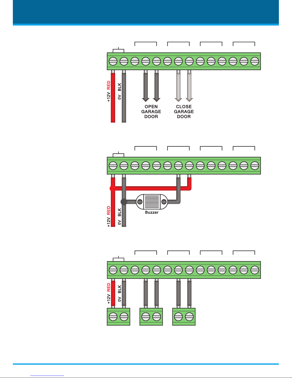
Connecting Trigger Devices
The WIR404 can be used to control various trigger devices. We have shown wiring
diagrams for some of the most common trigger devices below and overleaf.
When trigger devices are connected you will need to set the latching mode as explained on
page 15.
12V DC
/ GND
NC NC NC NCNO NO NO NOCOMCOM CO
MC
OM
Channel 1Channel 2Channel 3Channel 4
Electronic Door Release
A simple electronic door
release allows you to
unlock a door using a key
fob or key pad.
14
www.Zendit.co
4Ch Wireless Receiver
12V DC
/ GND
NC NC NC NCNO NO NO NOCOMCOM CO
MC
OM
Channel 1Channel 2Channel 3Channel 4
12V DC
/ GND
NC NC NC NCNO NO NO NOCOMCOM CO
MC
OM
Channel 1Channel 2Channel 3Channel 4
12V DC
/ GND
NC NC NC NCNO NO NO NOCOMCOM CO
MC
OM
Channel 1
12V AUXKey Switch P.A Circuit
Channel 2Channel 3Channel 4
Opening & Closing An
Electric Garage Door
By using two relays you can
wire the receiver to operate
an electronic garage door.
One channel is used to
open the door and a
second channel is used to
close the door.
Operating A 12V Buzzer
A simple but eective use
of a single channel is to
operate a 12V buzzer.
An easy way to sound an
audible warning at the
push of a button.
The example shows a buzzer
connected to channel 2.
Operating An Alarm
Panel
Two channels can be used
to control an alarm panel.
In the example on the right
channel 1 would be used
to arm and disarm the
alarm. Channel 2 would be
used as a P.A. alarm.

15www.Zendit.co
4Ch Wireless Receiver
Latching Modes
The WIR404 has two Latching modes which control how
long the relay is active, Latching and Non-Latching.
Latching acts as an On/Off switch. When the transmitter
is pressed the relay will stay active until the transmitter is
pressed again.
Non-Latching mimics the press of the transmitter and will
only remain active as long as the transmitter is pressed.
(Not compatible with WIR305 key pads)
The Latching mode is set by the position of a dip switch on
the PCB.
To gain access you will rst need to remove the
cover by unscrewing the small locking screws on either
side of the unit. The front panel can then slide up and o .
Once removed you will see 4 dip switches on the top of
the PCB labelled 1 to 4. To set a channel to Latching ick
the corresponding dip switch to On. To set a channel to
Non-Latching ick the corresponding dip switch towards
the channel number.
Basic Operation
The 4ch receiver has 4 numbered push buttons on the
front of the unit so that the 4 relays can be controlled from
the receiver itself.
This makes it a great option for central locations such as a
reception desk or security offi ce where an operator could
control security barriers or an electronic door release to
grant access to visitors.
Members of sta would gain access as and when they
needed using key fob and key pad transmitters.
Latching
Non-Latching

www.Zendit.co
All specications are approximate. We reserve the right to change any
product specications or features without notice. Whilst every eort
is made to ensure that these instructions are complete and accurate,
Zendit cannot be held responsible in any way for any losses, no matter
how they arise, from errors or omissions in these instructions, or
the performance or non-performance of the equipment that these
instructions refer to.
WEE/CG0783SS
This symbol on the products and/or accompanying
documents means that used electronic equipment must
not be mixed with general household waste. For treatment,
recovery and recycling please return this unit to your trade
supplier or local designated collection point as dened by
your local council.
© Copyright Zendit 2017
Date Installed:
For further support or to order additional products please contact your installer below:
Company Name:
Installer's Name:
Phone:
Email:
Website:
Address:
*IDQ00000*
Internal use only
For more information on the Zendit
range of products visit www.Zendit.co
or scan the QR code to the left.
 Loading...