


ZD-VT1 User Guide
ZENDA GPS Tracker ZD-VT1 User Guide

ZD-VT1 User Guide
Copyright © 2016 ZENDA GPS All rights reserved. - 2 -
Change History
File Name
ZD-VT1 User Guide
Created By
Kyle Lv
Product
ZD-VT1
Creation Date
Update Date
2016-01-08
2016-02-02
Subproject
User Guide
Total Pages
16
Version
V1.0
Confidential
External Documentation

ZD-VT1 User Guide
Copyright © 2016 ZENDA GPS All rights reserved. - 3 -
Contents
1 Copyright and Disclaimer ...............................................................................................................................................................- 4 -
2 Product Overview ..........................................................................................................................................................................- 4 -
3 Product Function and Specifications .............................................................................................................................................- 4 -
3.1 Product Function ................................................................................................................................................................- 4 -
3.1.1 Position Tracking ......................................................................................................................................................- 4 -
3.1.2 Anti-Theft .................................................................................................................................................................- 4 -
3.1.3 Other Functions .......................................................................................................................................................- 4 -
3.1.4 Functions of Optional Accessories ...........................................................................................................................- 5 -
3.2 Smart Voice .........................................................................................................................................................................- 5 -
3.3 Smart Sleep Mode ..............................................................................................................................................................- 5 -
3.4 Data Compression Mode – CCC ..........................................................................................................................................- 5 -
3.5 Specifications ......................................................................................................................................................................- 6 -
4 ZD-VT1 and Accessories .................................................................................................................................................................- 6 -
5 Product View .................................................................................................................................................................................- 7 -
6 First Use .........................................................................................................................................................................................- 8 -
6.1 Installing the SIM Card ........................................................................................................................................................- 8 -
6.2 LED Indicator .......................................................................................................................................................................- 9 -
6.3 Configured by Computer ....................................................................................................................................................- 9 -
6.4 Tracking by Mobile Phone .................................................................................................................................................- 10 -
6.5 Common SMS Commands ................................................................................................................................................- 11 -
6.5.1 Setting Authorized Phone Numbers.......................................................................................................................- 11 -
6.5.2 Setting Anti-Theft (Arming/Disarming) ..................................................................................................................- 11 -
7 ZENDA Tracking System ...............................................................................................................................................................- 12 -
8 Installing the ZD-VT1....................................................................................................................................................................- 13 -
8.1 (Optional) Installing the GPS Antenna ..............................................................................................................................- 13 -
8.2 Installing an I/O Cable .......................................................................................................................................................- 13 -
8.2.1 Define a Port ..........................................................................................................................................................- 13 -
8.2.2 Port View ...............................................................................................................................................................- 14 -
8.2.3 Power Cable/Ground Wire .....................................................................................................................................- 14 -
8.2.4 ACC and Door Detection ........................................................................................................................................- 15 -
8.2.5 Remote Power Cut-off ...........................................................................................................................................- 16 -
8.2.6 (Optional) Buzzer Alarm .........................................................................................................................................- 16 -
8.3 Mounting the ZD-VT1 .......................................................................................................................................................- 16 -

ZD-VT1 User Guide
Copyright © 2016 ZENDA GPS All rights reserved. - 4 -
1 Copyright and Disclaimer
The user manual may be changed without notice.
Without prior written consent of ZENDA, this user manual, or any part thereof, may not be reproduced for any purpose
whatsoever, or transmitted in any form, either electronically or mechanically, including photocopying and recording.
ZENDA shall not be liable for direct, indirect, special, incidental, or consequential damages (including but not limited to
economic losses, personal injuries, and loss of assets and property) caused by the use, inability, or illegality to use the product
or documentation.
2 Product Overview
The ZD-VT1, a GPS vehicle tracker, is used for private vehicle anti-theft, official vehicle anti-theft, and personal tracking
management. The tracker supports smart-voice commands for arming/disarming settings, device status query, and location
query for a long time.
3 Product Function and Specifications
3.1 Product Function
3.1.1 Position Tracking
GPS + GSM dual-module tracking
Real-time location query
Track by time interval
Track by distance
Track by mobile phone
Speeding alarm
Direction change alarm
Geo-fence
3.1.2 Anti-Theft
SOS alarm
GPS antenna cut-off alarm
External power cut-off alarm
GPS blind spot alarm
Remote engine cut-off alarm
Engine or vehicle door status alarm
Towing alarm
Arming or disarming
3.1.3 Other Functions
SMS/GPRS (TCP/UDP) communication (ZENDA protocol)
Built-in 1 MB buffer for storing 5,000 GPRS cache and 128 SMS cache
Mileage report

ZD-VT1 User Guide
Copyright © 2016 ZENDA GPS All rights reserved. - 5 -
Low battery alarm
Smart sleep mode
Smart voice setting
3.1.4 Functions of Optional Accessories
Accessory
Function
Buzzer
Anti-theft
Microphone
Listen-in
GPS antenna
Improve GPS reception.
3.2 Smart Voice
Dial the ZD-VT1 SIM card number by using an authorized mobile phone number to set the smart voice function. After dialing,
the following voice prompt is played: "Hello. Arming, press 1; disarming, press 2; query arming status, press 3; query a location,
press 4; listen-in, press 5. Thank you." Then, press the desired number on the phone to enable a function.
For details about the arming and disarming functions, see section 6.5.2 "Setting Anti-Theft (Arming/Disarming)".
Note: Before using the smart voice function, ensure that:
Your phone number has been authorized.
The SIM card used in the ZD-VT1 has subscribed the caller ID service. Otherwise, you cannot use the smart voice function.
3.3 Smart Sleep Mode
The smart sleep function works in conjunction with the following.
Scenario 1: When the ACC detection line has not been used.
With no interruption for consecutive 15 minutes, the tracker enters smart sleep mode. In this way, the GPS module stops work,
and the tracker stops uploading data. Heartbeat reports about GPS invalid will be sent to the platform every 60 minutes (the
default interval can be changed). If vibration occurs, the tracker will awake and continue to operate and report data at the
specific interval. Heartbeat reports will be also resumed.
Scenario 2: When the ACC detection line has been connected.
If the ACC is on, the tracker will operate normally and report data at the specific interval.
If ACC is off, without any vibration, the tracker immediately enters smart sleep mode (as same as Scenario 1); Heartbeat reports
about GPS invalid will be sent to the platform every 60 minutes (the default interval can be changed). If vibration occurs or the
engine starts, the tracker will awake and continue to operate and report data at the specific interval.
Note:
When the tracker is being charged with a USB cable, it will operate normally, but will not enter smart sleep mode.
Under smart sleep, the tracker has low power consumption. The tracker with built-in battery can sustain up to about 50
hours.
3.4 Data Compression Mode – CCC
Device communicates through ZENDA protocol. The header and tail of a data packet stay unchanged, but the middle part of the
data packet has been uploaded with CCC data compressed format. For details about the CCC data format, refer to ZENDA GPRS
Protocol.
Note: Only proactively-uploaded data (such as timing, heartbeat, or alarm events) is uploaded in CCC data format. Commands
sent by the platform and replied by the tracker have the same format as the commands in ZENDA GPRS Protocol.

ZD-VT1 User Guide
Copyright © 2016 ZENDA GPS All rights reserved. - 6 -
3.5 Specifications
Item
Specifications
Dimension
70.5 mm x 54 mm x 19.5 mm
Weight
65g
Input voltage
DC 11 V to 36 V/1.5 A
Standby battery
350 mAh/3.7 V
Power consumption
45 mA normal working current (12 V; ACC ON; upload data every 10 seconds; average
current)
Standby power consumption
6.5 mA (12 V; ACC OFF; no data uploading; average current)
Power consumption of the
internal battery
90 mA (3.8 V; GPS ON; upload data every 10 seconds; average current)
Battery standby power
consumption
7 mA (3.8 V; GPS OFF; no data uploading while GSM standby; average current)
Operating Temperature
-20°C to 55°C
Operating humidity
5% to 95%
Working Hour
50 hours in power-saving mode and 3.5 hours in normal working mode
LED indicator
3 indicators, showing GSM, GPS, and power status
Button/Switch
1 SOS button (for sending SMSs or dialing)
1 power button
1 positive or negative door trigger switch (in the position where you insert a SIM card)
Memory
1 MB buffer (for storing 5,000 GPRS cache and 512 SMS cache)
Sensor
Vibration sensor
GSM frequency band
GSM 850/900/1800/1900 MHz
GPS sensitivity
-161 dB
Positioning accuracy
10m
GSM antenna
Internal antenna
GPS antenna
(Optional) Internal/external MMCX antenna
I/O port
3 inputs, including 1 SOS, 1 door trigger (positive or negative), and 1 ACC detection
2 outputs, including 1 buzzer and 1 remote fuel cut-off circuit
1 analog detection input
1 USB port (used for charging and parameter configuration)
4 ZD-VT1 and Accessories
Standard accessories:
Tracker with a built-in battery
I/O cable
USB cable
ZD-VT1 Quick Installation Guide

ZD-VT1 User Guide
Copyright © 2016 ZENDA GPS All rights reserved. - 7 -
Optional accessories:
Buzzer
GPS antenna
Audio cable + Microphone
5 Product View
Microphone
Power & functional cable interfaces
GPS antenna interface
Power/GSM/GPS
indicators
USB port

ZD-VT1 User Guide
Copyright © 2016 ZENDA GPS All rights reserved. - 8 -
SIM card slot
A switch for input 3 line to switch between a (+)
trigger or a (-) trigger
Power switch
6 First Use
6.1 Installing the SIM Card
The following figure shows the SIM card slot:
SIM card
Remove the SIM card cover, and insert the SIM card into the card slot.
Note:
Ensure that the SIM card has sufficient balance.
Ensure that the phone card PIN lock has been closed properly.
Ensure that the SIM card in the ZD-VT1 has subscribed the caller ID service if you want to use your authorized phone
number to call the tracker.
Power off the tracker before installing the SIM card.

ZD-VT1 User Guide
Copyright © 2016 ZENDA GPS All rights reserved. - 9 -
6.2 LED Indicator
GSM indicator (green) Power indicator (red) GPS indicator (blue)
Use any of the following ways to start the ZD-VT1:
Press and hold down the power button for 3 to 5 seconds.
Connect the ZD-VT1 to a computer by using a USB cable.
Connect the ZD-VT1 to an external power supply.
Note: When the ZD-VT1 is being charged with a USB cable or by external power supply, it will operate normally. To restart the
ZD-VT1, just press and hold down the power button.
GPS Indicator (Blue)
Steady on
The GPS antenna is faulty.
Steady off
The GPS stops.
Blink (0.5s on and 2.5s off)
The GPS is valid.
Blink (1s on and 2s off)
The GPS is invalid.
GSM Indicator (Green)
Steady on
A call is coming in or busy.
Steady off
The SIM card is not inserted or is faulty.
Blink (0.5s on and 2.5s off)
The GSM signal is received.
Blink (1s on and 2s off)
The GSM signal is not received.
Power Indicator (Red)
Steady on
The ZD-VT1 is charging.
Blink (0.5s on and 2.5s off)
The ZD-VT1 works normally.
Blink (1s on and 2s off)
The ZD-VT1 power is low.
6.3 Configured by Computer
This section describes how to use ZENDA Manager to configure the ZD-VT1 on a computer.
Procedure:
1. Install the USB-to-serial cable driver and ZENDA Manager.
2. Connect the ZD-VT1 to a PC with the USB-to-serial cable.
3. Run ZENDA Manager, then the following dialog box will appear:

ZD-VT1 User Guide
Copyright © 2016 ZENDA GPS All rights reserved. - 10 -
Turn on the device, then ZENDA Manager will detect the device model automatically and the parameter page will appear
accordingly.
For details about ZENDA Manager, see the ZENDA Manager User Guide.
6.4 Tracking by Mobile Phone
Perform the following steps to query a location:
1. Use a mobile phone with an authorized phone number to call the tracker. It will enter the smart voice mode
automatically.
2. Press 4 on the mobile phone according to the voice prompt. The device will reply an SMS with a map link.
3. Click the SMS link. The location will be displayed on Google Maps on your mobile phone.
Note: Ensure that the ZD-VT1 SIM card number has subscribed the caller ID service. Otherwise, the caller ID will be blocked.
SMS example:
Now,110721 16:40,V,10,0Km/h,97%,http://maps.meigps.com/?lat=22.513015&lng=114.057235
The following table describes the SMS format:
Parameter
Description
Remarks
Now
Indicates the current location.
SMS header: indicates the alarm type.
110721 16:40
Indicates the data and time in
YYMMDD hh:mm format.
None
V
The GPS is invalid.
A = Valid
V = Invalid
10
Indicates the GSM signal strength.
Value: 1–32
The larger the value is, the stronger the signal is. If

ZD-VT1 User Guide
Copyright © 2016 ZENDA GPS All rights reserved. - 11 -
the value is greater than 12, GPRS reaches the
normal level.
0Km/h
Indicates the speed.
Unit: km/h
97%
Indicates the remaining battery power.
None
http://maps.meigps.co
m/?lat=22.513015&lng
=114.057235
This is a map link.
Latitude : 22.513015
Longitude : 114.057235
None
If your mobile phone does not support HTTP, enter the latitude and longitude on Google Maps to query a location.
6.5 Common SMS Commands
6.5.1 Setting Authorized Phone Numbers
Command: 0000,A71,Phone number 1,Phone number 2,Phone number 3
Reply: IMEI,A71,OK
Description:
Phone number: a maximum of 16 bytes. If no phone numbers are set, leave them blank. Phone numbers are empty by default.
Phone number 1/2/3: SOS phone numbers. When you call the device by using these phone numbers, the following information
will be received: SMSs about the location, geo-fence alarm, and low battery alarm, and calls and SMSs about vehicle door
opening and ignition.
If you want to delete all authorized phone numbers, run 0000,A71.
When the SOS button is pressed, the tracker dials phone numbers 1, 2, and 3 in sequence. The tracker stops dialing when a
phone number responds. If the call is not answered after phone number 3 is dialed, the dialing ends.
Example: 0000,A71,13811111111,13822222222,13833333333
Reply: 353358017784062,A71,OK
6.5.2 Setting Anti-Theft (Arming/Disarming)
You can set anti-theft by SMS command, call, or platform command.
Note: You can use a buzzer (optional accessory) to enhance the anti-theft protection. Set an authorized phone number to
ensure that SMSs and calls can be received when a vehicle is stolen.
Set by smart voice: Dial the ZD-VT1 SIM card number by using an authorized mobile phone number to set the smart voice
function. After dialing, the following voice prompt is played: "Hello. Arming, press 1; disarming, press 2; query arming

ZD-VT1 User Guide
Copyright © 2016 ZENDA GPS All rights reserved. - 12 -
status, press 3; query a location, press 4; listen-in, press 5. Thank you." Then you press 1 to set arming.
Set by SMS command: Set arming or disarming by SMS command.
SMS command: 0000,B21,Status
Response: IMEI,B21,OK
Note:
When Status is 1, enable the anti-theft function. While arming, opening the vehicle door and starting the ACC are
not allowed. Otherwise, the ZD-VT1 will send an alarm SMS and make a call to the preset authorized phone number.
When Status is 0, disable the anti-theft function. While disarming, all anti-theft alarms will be cleared. The device is
in disarming state by default.
Function
Call
SMS
Engine
Cut
Buzzer
Remarks
Opening the vehicle
door
√
√ √
When the vehicle door is opened without permission, the buzzer
will sound continuously until the anti-theft state is cancelled. The
tracker will dial the three authorized phone numbers in sequence
and send SMSs.
Starting the engine
√ √ √
√
When the engine is started, the vehicle fuel will be cut off, and the
buzzer will sound continuously until the anti-theft state is
cancelled. The tracker will dial the three authorized phone numbers
in sequence and send SMSs.
Setting arming while
driving (Intercepting the
moving vehicle )
√
√
After the vehicle is stolen, you can send a GPRS/SMS command to
intercept the moving vehicle. When the vehicle speed is lower than
5 km/h, the engine will be cut off, and the tracker will send an alarm
to authorized phone numbers.
Towing alarm
√
√ √
When the ACC is off and vibration occurs continuously, a towing
alarm will be generated. The tracker will dial the three authorized
phone numbers in sequence and send SMSs.
Engine cut: Output ports are activated, implementing remote fuel and power cut-off functions. For details, see section 8.2.5
"Remote Power Cut-off."
For details about SMS commands, see the ZENDA SMS Protocol.
Note:
1. The default SMS command password is 0000. You can change the password by using ZENDA
Manager and SMS
commands.
2. The device can be configured by SMS commands with a correct password. After an authorized phone number is set, only
the authorized phone number can receive the preset SMS event report.
7 ZENDA Tracking System
Visit www.zendatracking.com, enter the user name and password, and log in to the ZENDA tracking system. (Purchase the login
account from your provider.)
For more information about how to add a tracker, see the ZENDA GPS Tracking System User Guide.
The ZENDA tracking system supports the following functions:
Track by time interval or distance.
Query historical traces.

ZD-VT1 User Guide
Copyright © 2016 ZENDA GPS All rights reserved. - 13 -
Bind driver and vehicle information.
View various reports.
Send commands in batches.
For details, see the ZENDA GPS Tracking System User Guide.
8 Installing the ZD-VT1
8.1 (Optional) Installing the GPS Antenna
If the GPS antenna is installed in a vehicle and the signal is weak, install an external GPS antenna to improve signal reception.
Connect the GPS antenna to the GPS port. The antenna had better face towards the sky. Fasten the antenna by using the glue.
Note: Do not install the GPS antenna at places where metals cover.
8.2 Installing an I/O Cable
8.2.1 Define a Port
The I/O cable is a 12-pin cable, including the power port, analog input port, positive input port, negative input port, and output
port.
1
SOS Ground Wire
(Black)
3
SOS
(White)
5
Output 1
(Yellow)
7
Output 2
(Orange)
9
Input 2
(Brown)
11
Input 3
(Grey)
2
Device Input Power
(Red)
4
Device Ground Wire
(Black)
6
Ground Wire
(Black)
8
- (Yellow)
10
- (Green)
12
Analog Input
(Blue)
No.
Function
Description
1
SOS ground wire
Used for input 1 (SOS) triggering.
2
Device input power
DC 11 V to DC 36 V
Undervoltage and overvoltage protection
3
Input 1 (SOS)
Negative trigger
When input 1 is activated or the SOS button is pressed, an alarm is
ZD-VT1 User Guide
Copyright © 2016 ZENDA GPS All rights reserved. - 14 -
generated.
4
Device ground wire
Connect to the negative electrode of the vehicle battery.
5
Output 1 (fuel cut-off circuit)
Power: 1 W; 0 V to 100 V
Connect to the relay for fuel or power cut-off
6
Ground wire
None
7
Output 2 (buzzer alarm)
Connect to the negative electrode of the buzzer alarm
8 - None
9
Input 2 (ACC input)
Positive triggering
High level input (3 V to 60 V)
Used for ACC detection by default
10 - None
11
Input 3 (door triggering)
The high level or low level triggering can be set. The negative triggering is
selected by default.
It is controlled by a DIP switch (near the SIM card slot).
Used for vehicle door detection.
12
Analog input
0 V to 47 V AD detection
Connect to sensors with various voltage output.
Formulas for calculating AD analog:
AD1/100 (External analog detection value)
AD4/100 (AD4 is the built-in battery voltage by default.)
AD5/100 (AD5 is the external power voltage by default.)
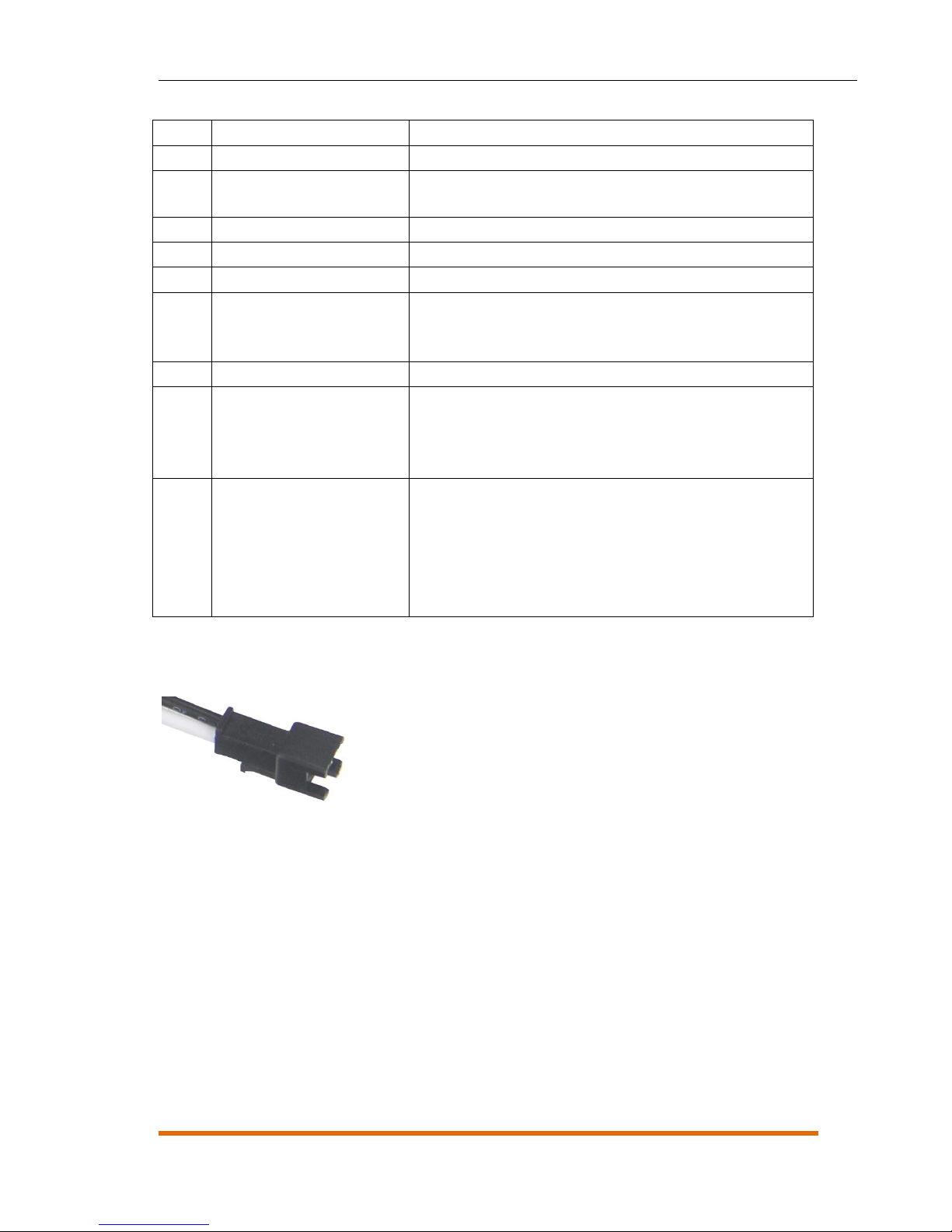
8.2.2 Port View
Digital input 1 (SOS)
8.2.3 Power Cable/Ground Wire
Connect the power cable (red) and ground wire (black) to the positive and negative electrodes of the vehicle battery
respectively.

ZD-VT1 User Guide
Copyright © 2016 ZENDA GPS All rights reserved. - 15 -
8.2.4 ACC and Door Detection
Different models of cars may be triggered differently. Connect the door detection after a correct trigger mode is set for the
tracker.

ZD-VT1 User Guide
Copyright © 2016 ZENDA GPS All rights reserved. - 16 -
8.2.5 Remote Power Cut-off
Note: To implement remote fuel and power cut-off, connect the relay to the fuel pump power cable or the engine power cable
in series.
8.2.6 (Optional) Buzzer Alarm
Buzzer output
8.3 Mounting the ZD-VT1
Fasten the ZD-VT1 in the vehicle by using cable ties.
The portable tracker can be connected to a cigarette lighter of the vehicle through an RS232 port by using a USB cable (5V
input).
 Loading...