

Modular Micro Data Centre Solutions
Installation Manual
zelladc.com

Table of Contents
1. Introduction 3
2. Safety Instructions 4
3. Power Connection 5
4. Access Control 8
5. Single & Dual Cooling System Commissioning Steps 9
6. PDView Access 15
7. Pyrorack Commissioning & User Guide 18
8. Start-up & Ready for Population 23
1. Introduction
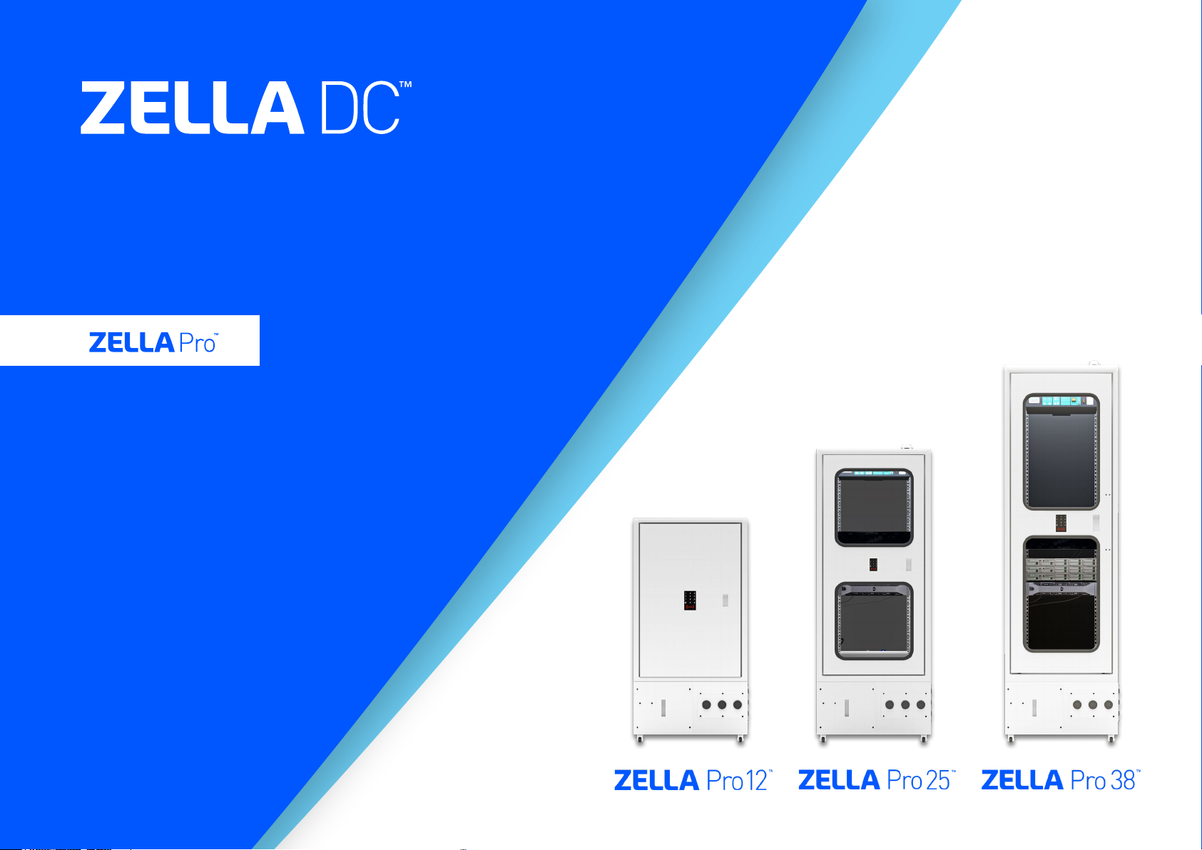
A Micro Data Centre is a stand-alone housing unit that replicates
all of the cooling, security and power capabilities of a traditional
data centre on a much smaller, lower cost scale. It miniaturizes the
data centre into the size of an average refrigerator, offering its own
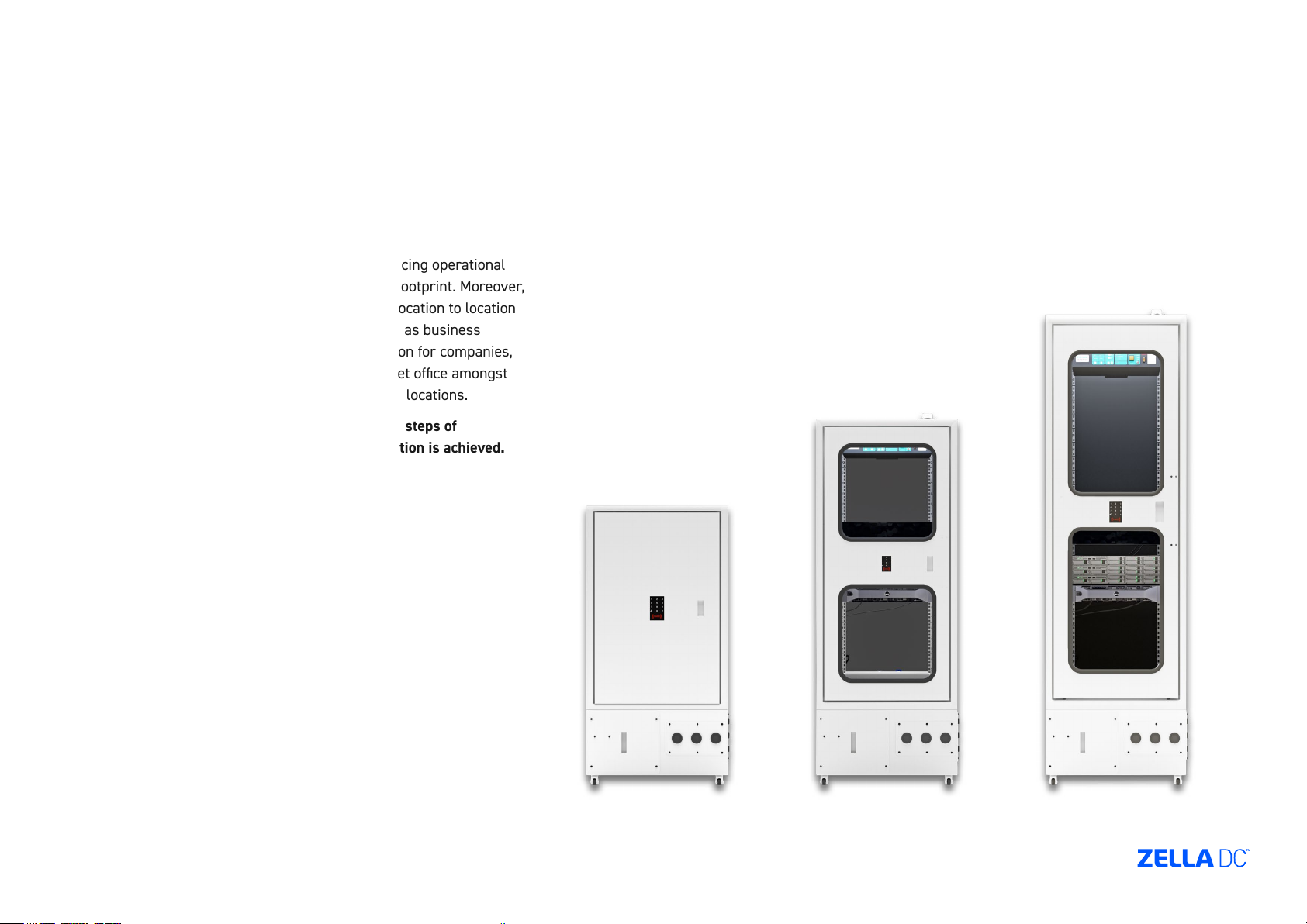
cooling and power capabilities, signicantly reducing operational
and energy costs by 30-60%, and on-premise IT footprint. Moreover,
it allows for portability and can be moved from location to location
and expanded to a set of “modular’’ data centres as business
grows. Micro Data Centres are the perfect solution for companies,
which must house critical infrastructure in a quiet ofce amongst
personnel through to infrastructure-poor remote locations.
This guide needs to be followed according to the steps of
installation to ensure the most effective installation is achieved.

2. Safety Instructions
2.1 Overview
This manual contains instructions relating to safety, installation,
operation, maintenance and warranty of this product and its
components.
Please keep this manual in a safe place for future references.
Handling Safety
Do not lift heavy loads without assistance.
Important safety note
z Caution needs to be taken when removing the
side panels of the Micro Data Centre, in particular
when dealing with the 38U as they are heavy.
We recommend a 2 man lift when removing and
re-installing the side panels.
<18 kg
32–55 kg
18–32 kg
>55 kg
z ALWAYS ENSURE the bottom brackets are locked in
and that the top pins are COMPLETELY slotted in.
z Don’t turn on the cooling system RCD until the
the wiring is completed between the Zella Pro and
external condenser.

3. Power Connection
3.1 Power Supply Requirements
Important note
DEPENDING ON SIZE AND MODEL. Power consumption can vary
from less than 10 amps and up to 60 amps depending on load.
When arranging the on-premise power supply with the landlord
or power company make sure you structure your energy bill
based on power used and not based on a xed power supply.
For security purposes we recommend a hardwired connection
directly into power source rather than a plug.
Max power supply to Zella Pro can either be 10, 32 & 60 amps
(220v – 240v / 50/60hz) depending on the model
WE RECOMMEND THAT INSTALLATION SHOULD ONLY
BE CARRIED OUT BY SUITABLY QUALIFIED ELECTRICAL
CONTRACTOR WITH THE NECESSARY TRAINING.
3.2 Switchboard Operation
Following the connection to mains power
DEPENDING ON MODEL THE SWITCHBOARD LAYOUT AND
CONFIGURATION IS DIFFERENT. (SEE LAYOUT DIAGRAMS –
pages 6-9)
Start Up Procedure
z Switch Mains Isolator switch to the ON position
z Very Important - Leave the Cooling System circuit breaker in
the OFF position – Electrical Hazard
z Please Note: If hardwiring 6 or 8KVA UPS – LEAVE IN OFF
POSITION until UPS and switchboard have been connected
by electrician – Electrical Hazard. (See UPS Manual)
z Switch UPS to the ON position once connected
z Important - (Leave the RCD cooling and Cooling system for
the air conditioner contractor – Electrical Hazard)
3. Power Connection
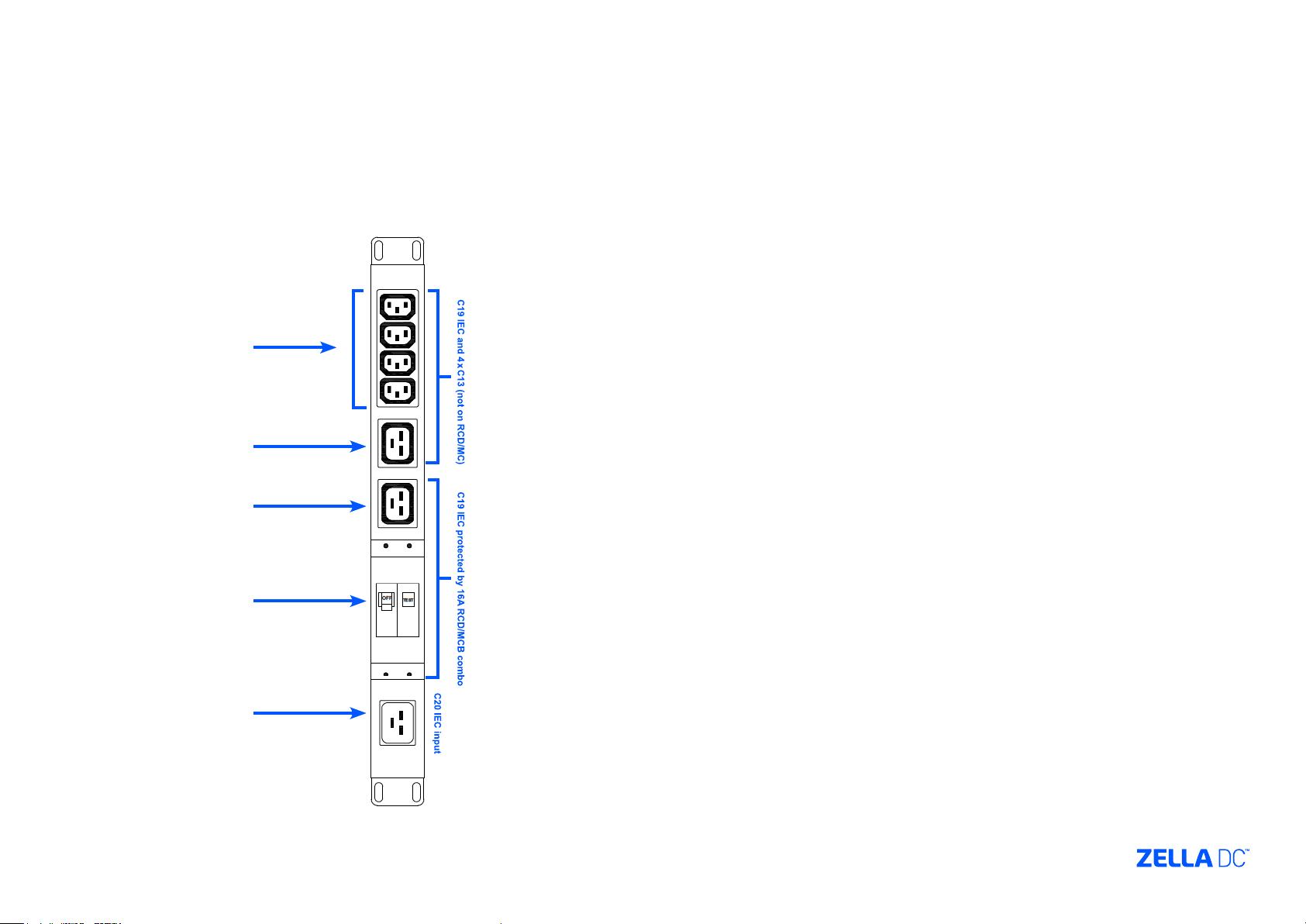
3.3 Power Supply diagram to PDU switchboard
Non-monitored sockets
UPS Power
Cooling system
Cooling system
RCD
Mains power
3. Power Connection
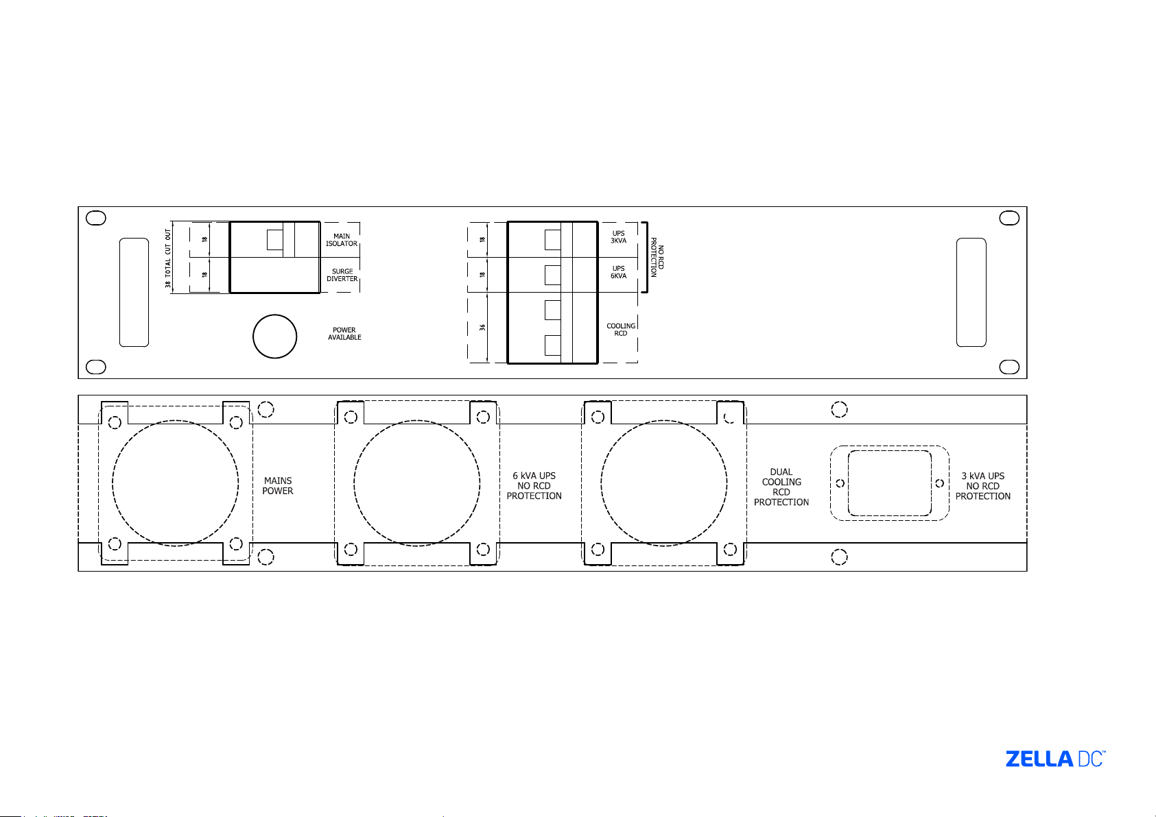
3.4 Switchboard layout
Front View
Rear View

4. Access Control
4.1 Metal Key Pad Operation
The default code for the doors are pre-set in the factory
as follows:
z Front door - 2580
z Back door – push button
FOR FURTHER INSTRUCTION TO PROGRAM DOOR
CODES. SEE USER MANUAL
Front panel description
Mode
Indicator
Door
Indicator
Antenna
(AC-Q42 & AC-Q44 only)
3 x 4
Matrix
Keypad
4.2 Biometric / Card Reader
The Zella Pro is supplied with a default card which will
open the front door. The rear door is opened by the push
button located inside the Zella Pro.
See user manual for programming options. Use card
reader until you are ready for biometric access mode.
Card reader
Fingerprint reader
4.3 L.E.D. Key Pad Operation
The default code for the doors are pre-set in the factory
as follows:
z Front door – 2580#
z Back door – push button
FOR FURTHER INSTRUCTION TO PROGRAM DOOR
CODES. SEE USER MANUAL
Key Pad
Card reader
Bell Button
(with BL-D40)
Case Screw
5. Single & Dual Cooling System Commissioning Steps
Important Safety Warning
BEFORE PLUGGING THE EXTERNAL CONDENSER POWER CABLES
(ORANGE AND GREY) TO THE BACK OF THE ZELLA PRO. ENSURE
THE COOLING SYSTEM RCD IS OFF ON THE BASE MOUNTED
SWITCHBOARD
You also have the option to unplug the cooling system/s power
cables from the back of the switchboard during the commissioning
process
PLEASE ENSURE THERE IS POWER TO THE Zella Pro
(SWITCHBOARD) BEFORE COMMISSIONING THE COOLING SYSTEM
5.1 Condenser
Depending on the model and cooling capacity the condenser
maximum distance can vary between 20 and 30 meters. The Zella
Pro is supplied with relevant cable length (3 core orange output
to condenser & 4 core grey cable. The condenser draws its power
from the Zella Pro. The condenser size and weight can also vary
depending on model and cooling capacity. The condenser will be
positioned either on the outer wall of the building or on the roof.
5.3 Wiring
The Zella Pro is supplied with all the cables (orange and grey)
which is pre-coiled and ready to be run with the copper piping
during the commissioning process. The pre-coiled condenser
cables are located inside the Zella Pro.
CONTRACTORS TO ENSURE BOTH ORANGE AND GREY CABLES
ARE LOCKED BY TURNING THE YELLOW DISK ON THE SIDE OF THE
CABLE PLUGS WITH A SCREW DRIVER. THE AIR CONDITIONING
CONTRACTOR MUST SUPPLY THEIR OWN COPPER PIPING.
WIRING TABLE (WHITE CABLE)
1 - Live Red / Brown
2 - Neutral Blue / Black
3 - Signal White
Green / Yellow Earth / Ground
5.2 Commissioning
Once the Zella Pro has been positioned in its proposed location and
connected to power the air conditioning contractor can commission
the cooling system.
Only once the air conditioning contractor has Connected wires to
the condenser and plugged the grey and orange cable into the Zella
Pro, can the cooling be turned on.
ENSURE THE COOLING SYSTEM PLUG IS PLUGGED INTO THE
CORRECT POWER SOCKET ON THE SWITCHBOARD
WIRING TABLE (ORANGE CABLE)
1 - Live Red / Brown
2 - Neutral Blue / Black
Green / Yellow Earth / Ground

5. Single & Dual Cooling System Commissioning Steps
5.3 Wiring cont.
Electrical Hazard – Ensure cooling system is in the OFF position on
Zella Pro base mounted switchboard and orange cooling system
plug is unplugged from rear of switchboard
Grey cable termination in condenser
(supplies power back to the Zella Pro)
(4 core cable)
1 – Brown
2 – Blue
3 – White
- Green / Earth
Orange cable termination in condenser
(supplies power to the external condenser)
(3 core cable)
L – Red
N – Blue
- Green / Earth

5. Single & Dual Cooling System Commissioning Steps
5.3 Wiring cont.
PLEASE NOTE: WHEN PLUGGING THE CABLE CONNECTORS, YOU SHOULD HEAR A CLICK TO CONFIRM CONTACT. AFTER INSERTING THE PLUG ENSURE
BOTH ORANGE AND GREY CABLES ARE LOCKED BY TURNING THE YELLOW DISK ON THE SIDE OF THE CABLE CONNECTOR WITH A SCREW DRIVER.
5. Single & Dual Cooling System Commissioning Steps
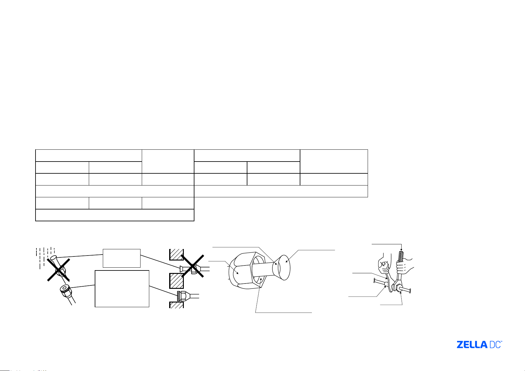
5.4 Copper Piping (refer to handout in Zella Pro)
1. Cut the pipe ends with a pipe cutter
2. Remove burrs with the cut surface facing downwards
so that the chips do not enter the pipe
3. Put the are nuts on pipe
4. Flare the pipe
Gas side
Liquid side
20/25/35 class 46 class 20/25/35 class 46 class
5. Check that the aring is properly made
6. Never use old or pre-used pipes
7. Do not use mineral oil on ared part
8. Incomplete aring may cause gas leakage
9. Use are nut xed to unit
Gas pipe thermal insulation
Liquid pipe thermal
insulation
O.D. 9.5mm O.D. 12.7mm O.D. 6.4mm I.D. 12-15mm I.D. 14-16mm I.D. 8-10mm
Minimum bend radius Thickness 10mm Min.
30mm or more 40mm or more 30mm or more
Thickness 0.8mm (C1220T-O)
Apply Oil Tighten
Rain
Be sure to
place a cap.
If no are cap is
available, cover
the are mouth
with tape to keep
dirt or water out.
Do not apply refrigeration oil
to the outer surface.
Wall
Flare nut
Do not apply refrigeration
oil to the are nut avoid
tightening with over torque.
Apply refrigeration oil to the
inner surface of the are.
10. Use torque wrenches when tightening the are nuts
11. Protect ends from dust
12. Use pipe bender
13. NEVER use pipes thinner than 0.8mm even when it is
available on the market.
Torque wrench
Spanner
Piping union
Flare nut
Please note: Pipe size is 9.5mm for cooling capacity 2kw up to 3.5kw (See enclosed manual with condenser)
5. Single & Dual Cooling System Commissioning Steps
<1+=/">%?;-<@
7-*5%,>139,*-.#*$+''#0-*,#--%0:,64*
J70*-.%,*%11+,-'3-%)02*#3$.*,#$-%)0*%,*
,.)=0*=%-.*311*%-,*5%,>139,*)0*8)'*-.#*
>+'>),#*)8*#@>1303-%)06K
A9B(9,4A:,9%
"CD6+*#$.*%56**&.+
7-*$.30:#,*-.#*-#/>#'3-+'#*,#--%0:64*
A3:#*BL
<1+=/">%?;-<@
7-*5%,>139,*-.#*$+''#0-*,#--%0:,64*
J70*-.%,*%11+,-'3-%)02*#3$.*,#$-%)0*%,*
,.)=0*=%-.*311*%-,*5%,>139,*)0*8)'*-.#*
>+'>),#*)8*#@>1303-%)06K
A9B(9,4A:,9%
"CD6+*#$.*%56**&.+
7-*$.30:#,*-.#*-#/>#'3-+'#*,#--%0:64*
A3:#*BL
P
P
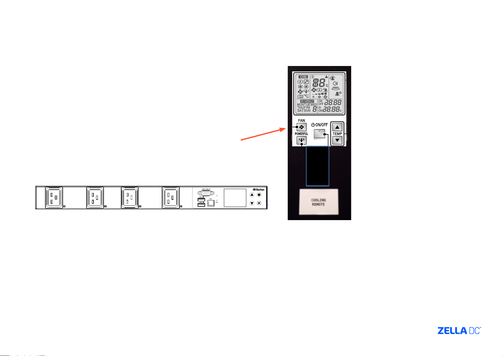
5.5 Start up Procedure – Single Cooling
ONLY once the condenser has been hardwired and copper piping connected can the
cooling system be turned on.
1. Insert cooling system IEC plug (orange cable) into the cooling system socket at
the rear of switchboard labelled (Cooling system).
2. Ensure switchboard is powered and both the Cooling System RCD and Cooling
System are in the ON position.
3. Start-up cooling system on remote located at the back door on left hand side.
4. Press the START button on the cooling system remote.
5. Ensure temperature is set to 23° on cooling mode and FAN STRENGTH is on HIGH.
6. Installation complete
Cooling Remote
Cooling System 1
Cooling System 2
ermanent Supply 1
ermanent Supply 2

5. Single & Dual Cooling System Commissioning Steps
<1+=/">%?;-<@
7-*5%,>139,*-.#*$+''#0-*,#--%0:,64*
J70*-.%,*%11+,-'3-%)02*#3$.*,#$-%)0*%,*
,.)=0*=%-.*311*%-,*5%,>139,*)0*8)'*-.#*
>+'>),#*)8*#@>1303-%)06K
A9B(9,4A:,9%
"CD6+*#$.*%56**&.+
7-*$.30:#,*-.#*-#/>#'3-+'#*,#--%0:64*
A3:#*BL
<1+=/">%?;-<@
7-*5%,>139,*-.#*$+''#0-*,#--%0:,64*
J70*-.%,*%11+,-'3-%)02*#3$.*,#$-%)0*%,*
,.)=0*=%-.*311*%-,*5%,>139,*)0*8)'*-.#*
>+'>),#*)8*#@>1303-%)06K
A9B(9,4A:,9%
"CD6+*#$.*%56**&.+
7-*$.30:#,*-.#*-#/>#'3-+'#*,#--%0:64*
A3:#*BL
5.6 Start up Procedure – Dual Cooling
1. ONLY once the condensers have been hardwired and copper piping been
connected can the cooling system be turned on.
2. Insert cooling system (IEC) plugs (Orange cable) into:
3. Plug Orange Cable (Labelled – Cooling system 1) into Permanent supply 1
4. Plug Orange Cable (Labelled – Cooling system 2) into Permanent supply 2
5. Ensure switchboard is powered and both the Cooling System RCD and Cooling
System are in the ON position
6. Start-up cooling system on remote located at the back door on left hand side.
7. Press the START button on the cooling system remote.
8. Ensure temperature is set to 23° on cooling mode and FAN STRENGTH is on HIGH.
9. Run both system together for 5 minutes – ensure both systems are operating.
10. Pull out both plugs without turning cooling system off from the permanent supply
and plug into Cooling systems 1 & 2 outlets.
11. One system will be operation following this step.
12. Installation complete
Cooling Remote
Cooling System 1
Cooling System 2
ermanent Supply 1
ermanent Supply 2

6. PDView Access
Default IP address is 192.168.0.192
Zella Pro PDU Conguration Guide
OPTION 1: To access the Zella Pro PDU using an smart device
(iPhone, iPod, iPad, andriod devise etc.) follow these steps:
1. Download the following App (Raritan PDView) from the Apple App Store,
2. Connect the Apple device with the app installed into the Zella Pro PDU/door
access portal,
3. Use the following to access:
a) Login: admin
b) Password: zellabox
c) Accept the terms of use check box. d) Once connected to the PDU the
following similar image should appear:
4. Access the ‘network’ icon located at the bottom of the screen. If you cannot see the
icon simply click on the nearest icon to the right of the screen and more options
will show.
5. At this point you will be able to locate the IP address for the unit. If you would like
to change the default IP address (192.168.0.1) you can do so at this stage.
6. Change the IP address status to ‘static’.
7. Change the IP address as desired.
8. Remember to save/apply changes at bottom of screen.

6. PDView Access
OPTION 2: To access the Zella Pro PDU using LAN
connections follow these steps:
Plug a CAT cable directly into the PDU and your computer,
Access a web browser,
Type the IP address allocated to the PDU into the web browser. At this
stage if you do not know the IP address go back to ‘OPTION 1’.
Press ‘enter’,
Use the following to access:
Login: admin
Password: zellabox
Accept the terms of use check box.
OPTION 3: To access the Zella Pro PDU through a network /
switch or something similar follow these steps:
Assign the desired IP address to the PDU by referring to ‘OPTION 1’ above,
Plug network cable / switch directly into the PDU,
Access a web browser,
Type the IP address allocated to the PDU into the web browser,
Press ‘enter’,
Use the following to access:
Login: admin
Password: zellabox
Accept the terms of use check box.
6. PDView Access
OPTION 4: To access the Zella Pro PDU through a
network / switch or something similar using DHCP
follow these steps:
Assign the desired IP address to the PDU by referring to
‘OPTION 1’ above,
Plug network cable / switch directly into the PDU,
Access the PDU through local Display,
If you have any questions please contact Zella DC:
Australia: 1300 117 644
International: + 61 8 6311 2814
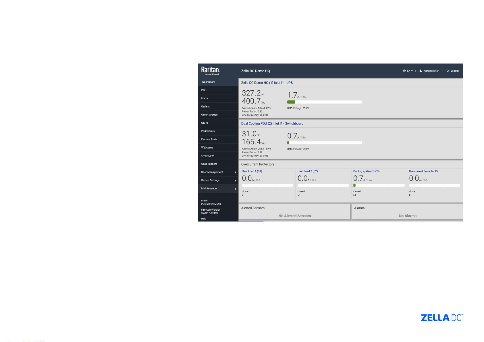
ONCE YOU HAVE ACCESSED THE PDU VIA WEB BROWSER
THIS IS WHAT YOU SHOULD SEE:

7. Pyrorack Commissioning & User Guide
IMPORTANT
For effective and safe installation follow the steps in the next few slides.
Please note: Accidental discharge will occur if this guide is not followed step by step.
For effective and safe installation follow the steps below See cannister connection quick guide.
Please note: Accidental discharge will occur if this guide is not followed step by step
Please print, laminate & stick near your Zella Pro for all to see the next 2 slides.

7. Pyrorack Commissioning & User Guide
IMPORTANT
For effective and safe installation follow the steps in the next few slides.
Please note: Accidental discharge will occur if this guide is not followed
step by step.
For effective and safe commissioning follow the steps below.
Please note: Accidental discharge will occur if this guide is not followed
step by step.
COMMISSIONING STEPS:
7.1 Preparation 1
Before mounting the Pyrorack into the Zella Pro. Make sure you have the
following ready:
1. Supplied fuses are ready (a pack of fuses should have arrived with
MDC)
2. Ensure keys are in slot at the front of the Pyrorack
3. Star (Phillips screw driver) ( to connect Pyrogen canister)
7.2 Preparation 2
1. Before mounting the Pyrorack, place the Pyrorack upside
2. down on a table.
3. Remove the four screws in the middle – surrounding the
4. string.
5. Remove the Pyrogen canister from the Pyrorack
6. Connect the Pyrogen canister to the Pyrorack by inserting
7. the plug and tightening the washer
8. Reinsert the canister back into the Pyroack
9. Place the Pyrorack into position top of the Zella Pro
10. 7.3 Commissioning Steps
1. Fit the Mains fuse F5 (far right hand side)
2. Insert mains supply cable (C13)
3. Wait 5 seconds
4. Fit the Battery Fuse F4 (middle fuse)
5. Wait 5 seconds
6. Fit the Extinguishing Agent Release Fuse F3. Wait 5 seconds, the
extinguishing agent fault LED goes off
7. Press and hold Test Button and conrm all LEDs are functioning
8. Ensure Key switch is in automatic mode
9. Pyrorack is successfully replaced into service
MAG UNIT
FUSE F3
500mA TL
D-CONN
MALE J2
D-CONN
FEMALE J1
BATTERY
FUSE F4
500mA TL
F5 500mA TL
7.4 Decommissioning Steps
1. Remove Mag fuse F3 from the rear of the Pyrorack (far left)
2. Wait 5 seconds
3. Remove the main fuse F4 (middle fuse)
4. Wait 5 seconds
5. Remove the mains cable
6. Remove the battery fuse F5. The unit shall be powered
7. down at this stage.
8. Remove the Pyrorack from the server cabinet.
7.5 Please print, laminate & stick the next 2 slides near your
Zella Pro for all to see.
MANS
FUSE

Warning
Fire Suppression System Information
z Before working within the Zella Pro ALWAYS ensure you follow these steps:
1. Turn key switch to manual
2. Isolate both zones 1 and 2 by pressing the isolate zones buttons located on the front panel
3. A beeping sound will continue intermittently as a reminder
4. Once you have completed work within the MDC and you are ready to close the doors press
the isolate buttons 1 and 2 once more
5. Turn the key switch back to the automatic position
6. The Pyrorack should return to normal status

7. Pyrorack Commissioning & User Guide
7.6 Pyrorack Canister Replacement
IMPORTANT
Decommission Pyroack rst
1. Remove Mag fuse F3 from the rear of the Pyrorack (far left)
2. Wait 5 seconds
3. Remove the main fuse F4 (middle)
4. Wait 5 seconds
5. Remove the mains cable
6. Remove the battery fuse F5. The unit shall be powered down at this stage.
7. Unplug environmental management cable
8. Remove the Pyrorack from the server cabinet.
9. Place on table upside down.
10. Unscrew the 4 screws in the middle of the Pyrorack.
11. Pull discharged canister out and unscrew cable attachment.
12. Replace with new canister.
13. Follow commissioning steps.
7.7 Important tips.
Before working within the Zella Pro ALWAYS ensure you follow these steps:
1. Turn key switch to manual
2. Isolate both zones 1 and 2 by pressing the isolate zones buttons located on the
front panel
3. A beeping sound will continue intermittently as a reminder
4. Once you have completed work within the MDC and you are ready to close the
doors press the isolate buttons 1 and 2 once more
5. Turn the key switch back to the automatic position
6. The Pyrorack should return to normal status
7. Please note, if you isolate power to the Pyrorack and the fuses are still inserted,
the Pyrorack will still be active as it has 24 hour internal battery backup.
MAG UNIT
FUSE F3
500mA TL
D-CONN
MALE J2
D-CONN
FEMALE J1
BATTERY
FUSE F4
500mA TL
MANS
FUSE
F5 500mA TL

8. Start-up & Ready for Population
The Zella Pro Micro Data Centre is a PLUG N PLAY unit therefore once it has
been installed by a qualied contractor the Micro Data Centre is ready for use!
1. Follow these steps to start up your unit:
z Start-up the switchboard
z Switch Mains Isolator A & B to the ON position
z Switch Cooling System switch to the ON position only when the
cooling system has been commissioned. Leave in the OFF position
until the air con contractor has installed.
z Switch UPS switch to the ON position
z Switch all remaining switches to the ON position
2. Follow Pyrorack Commissioning steps from the installation manual.
3. Populate the Micro Data Centre with your critical equipment and add
equipment labelling in PDView.
NOTE: Ensure adequate gaps are left between the equipment housed within
the Micro Data Centre to ensure an effective air-ow is maintained. The cooling
system will maintain the optimal cooling air-ow between the equipment if this
recommendation is adhered to.
NOTE: DO NOT exceed the cooling system’s recommended BTU/h specications
(listed in the cooling system section) as this will overheat the equipment.

Meet the uptime experts
Over a decade ago Zella DC pioneered the micro data centre. Since then, our nextgeneration server rooms have been proven to work in the harshest environments
on earth. The result is a vendor-agnostic approach to software, hardware
manufactured to global standards, and partners across ve continents.
Summary of solution benet
Uptime and
space usage
Cyber and
physical security
Email info@zelladc.com
Phone +61 (8) 6311 2814
Website zelladc.com
Risk from
human error
Energy and noise
efciency
Self-learning
and autonomy
Data
sovereignty
Scalability
as needed
Local storage/
fast processing
April 2021
 Loading...