

ZEKS Eclipse 120ZPA, Eclipse 300ZPA, Eclipse 200ZPA, Eclipse 160ZPA, Eclipse 400ZPA Technical Manual
...
TECHNICAL MANUAL
ZPA Heatless Purge
Desiccant Compressed Air Dryer
90-5000 scfm
NOTICE
Those operating the machine or performing
maintenance should read and understand
the decals positioned on the machine and
the contents of this Technical Manual.
Ensure that this Technical Manual is not
removed permanently from the machine.
ZEKS Compressed Air Solutions
1302 Goshen Parkway
West Chester, PA 19380
Phone: 610-692-9100
800-888-2323
Fax: 610-692-9192
Web: www.zeks.com
Form: ZEKS ZPA NEMA 1 V0813

TABLE OF CONTENTS
SECTION CONTENT PAGE
1. INTRODUCTION ............................................................................................. 2
2. ABBREVIATED WARRANTY .......................................................................... 2
3. ZPA HEATLESS DRYER NOMENCLATURE .................................................. 3
4. RECEIVING AND INSPECTION ..................................................................... 3
5. SAFETY AND OPERATION PRECAUTIONS ................................................. 4
6. PRINCIPLES OF OPERATION ....................................................................... 5
7. ALARMS AND INDICATORS .......................................................................... 7
8. INSTALLATION/INITIAL START-UP ................................................................ 8
9. SCHEDULED MAINTENANCE ....................................................................... 10
10. TROUBLESHOOTING .................................................................................... 13
11. PURGE CHARTS ............................................................................................ 14
12 GENERAL ARRANGEMENT DRAWINGS ...................................................... 18
13 WIRING DIAGRAMS ....................................................................................... 21
14 FLOW DIAGRAM ............................................................................................ 23
15 FILTER FLOW ................................................................................................. 25
16 FILTER ARRANGEMENT ................................................................................ 26
17 REPLACEMENT PARTS DIAGRAM ............................................................... 27
18 REPLACEMENT PARTS LIST ........................................................................ 30
ZEKS Eclipse ZPA 90-5000 Desiccant Dryers
www.zeks.com
1

1.0 INTRODUCTION
ZEKS Eclipse™ Heatless Desiccant Dryers are designed
to adsorb moisture from compressed air. The dryers are
constructed with two towers, each containing desiccantbeads, that alternate between online (drying) and offl ine
(regenerating) modes, yielding a continuous stream of dry
air at the dryer’s outlet.
During normal operation, wet air passes through the online
tower and water vapor from the air is adsorbed (collected)
on the desiccant beads. While air is being adsorbed in the
online tower, the moisture on the desiccant in the offl ine
tower is removed by a process called desorption (regeneration). After an initial rapid depressurization, a portion
2.0 ABBREVIA TED WARRANTY
ZEKS Eclipse™ heatless desiccant dryer products are
warranted to be free from defects in material and workmanship for a period of 12 months from the original date
of shipment from the factory . To allow the warranty to be in
effect for 12 months from the date of equipment start-up,
the Warranty Registration Card must be completed and
returned to ZEKS. Alternately, the Warranty Registration
Card may be completed online at www.zeks.com. The
total warranty period cannot exceed 18 months from the
original date of shipment from the factory.
Equipment must be installed and operated in accordance
with ZEKS’ recommendations. ZEKS liability is limited to
repair of, refund of purchase price paid for, or replacement in kind at ZEKS’ sole option, during the warranty
time period stated above. IN NO EVENT SHALL ZEKS
BE LIABLE OR RESPONSIBLE FOR INCIDENTAL OR
CONSEQUENTIAL DAMAGES, even if the possibility of
such incidental or consequential damages has been made
known to ZEKS Compressed Air Solutions. In addition, the
usual maintenance and replacement type products are not
covered by this warranty. See SECTION 9.
of dried air from the online tower passes over the desiccant bed and carries the moisture off the bed and out the
dryer’s exhaust.
The continuous, alternating process of adsorption and desorption is controlled using a timer that switches the towers in a specifi c timed sequence. Very dry compressed air
dew points are achieved through the continuous switching
and operation of this dryer. ZEKS offers dryers to provide
either -40°F, -80°F or -100°F pressure dew point outlet air.
The warranties expressed above are in lieu of and exclusive of all other warranties. There are no other warranties,
expressed or implied, except as stated herein. There are
no implied warranties of merchantability or fi tness for a
particular purpose, which are specifi cally disclaimed.
Valves – After the Basic Warranty noted above expires,
the diaphragm valves on the ZP A heatless dryers are warranted (parts only) for a total of 5 years from the date the
dryer is shipped from the ZEKS factory. The following applies to this warranty:
A. Check valves are excluded
B. Not applicable to dryers provided for -80°F and
-100°F dewpoint applications
C. Valves must be rebuilt every two years. Refer to
SECTION 9 of this manual
D. Control line air fi lter element must be replaced
once per year.
2
ZEKS Eclipse ZPA 90-5000 Desiccant Dryers
www.zeks.com
3.0 NOMENCLATURE
Nominal Flow Type/Design Voltage Electrical
SCFM* Series (Dew Point) NEMA Option
90 ZPA = Pressure Swing 1 = 115-1-60 (-40°F) 0 = NEMA 1 0 = Standard
120 G = 115-1-60 (-80°F) H = NEMA 4 A = Failure-To-Shift (FTS)
160 B = 115-1-60 (-100°F) S = NEMA 4X B = High Humidity (HH)
200 2 = 230-1-60 (-40°F) Stainless Steel C = FTS + HH
250 C = 230-1-60 (-100°F) E = Dew Point Display
300 3 = 220-1-50 (-40°F) + MLC (NEMA 4/4X)
400 E = 220-1-50 (-100°F) G = Dew Point Display + MLC
500 + FTS (NEMA 4/4X)
600 M = Moisture Load Control (MLC)
800 + FTS (NEMA 1 only)
1000 N = MLC + HH (NEMA 1 only)
1200
1500
1800
2100
2700
3300
4000
5000
* Nominal Flows indicated are
for 100F inlet temperature,
100
°F ambient temperature and
100 psig compressed air pressure.
! NOTICE
Nomenclature shown above represents standard
price sheet options. Other options are available refer to nomenclature insert specifi c to your dryer
for details.
4.0 RECEIVING AND INSPECTION
4.1 INSPECTION
Upon receiving your ZEKS air dryer, please inspect the unit
closely. If evidence of rough handling is detected, please
note it on your delivery receipt, especially if the dryer will
not be uncrated immediately. Obtaining the delivery person’s signed agreement to noted damages will facilitate
submission of insurance claims.
4.2 UNPACKING AND HANDLING
! NOTICE
Under no circumstances should any person attempt
to lift heavy objects without proper lifting equipment
(i.e.: crane, hoist, slings or fork truck). Lifting any unit
without proper lifting equipment can cause serious
injury.
Refer to labels on the dryer for the appropriate means for
lifting or moving the dryer. For those dryers that indicate
lifting via the structural skid, forks should extend all the
way through the skid to reduce unnecessary forces to the
dryer when moving. When lifting the dryer, ensure that
no stress is applied to the piping or the valves. Refer to
Section 8.2 for locating and mounting of dryer.
ZEKS Eclipse ZPA 90-5000 Desiccant Dryers
www.zeks.com
3
5.0 SAFETY AND OPERATION PRECAUTIONS
Because an air dryer is pressurized and contains mechanical parts, the same precautions should be observed
as with any piece of machinery of this type where carelessness in operation or maintenance is hazardous to personnel. In addition to the many obvious safety rules that
should be followed with this type of machinery, the safety
precautions as listed below must be observed:
1. Only qualifi ed personnel shall be permitted to adjust,
perform maintenance or repair this air dryer.
2. Read all instructions completely before operating unit.
3. Pull main electrical disconnect switch and disconnect
any separate control lines, if used, before attempting to
work or perform maintenance on the unit.
4. Do not attempt to service any part while dryer is in an
operational mode.
5. Do not attempt to remove any parts without fi rst reliev-
ing the entire air system of pressure.
6. Do not operate the dryer at pressures in excess of its
rating.
7. Inspect unit daily to observe and correct any unsafe
operating conditions.
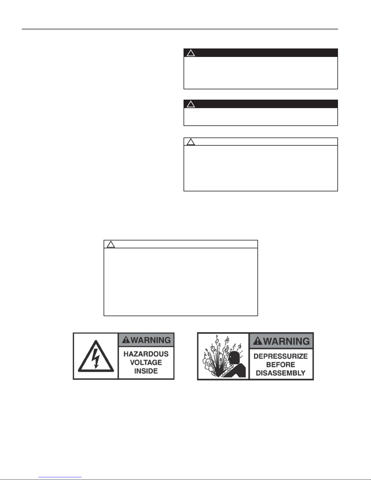
OSHA Heading Descriptions
! WARNING
“Warning” is used to indicate a hazardous situation which
has some probability of death or severe injury. Warning should not be considered for property damage accidents unless personal injury risk is present.
! CAUTION
“Caution” is used to indicate a hazardous situation which
may result in minor or moderate injury.
! NOTICE
“Notice” is used to indicate a statement of company
policy as the message relates directly or indirectly to
the safety of personnel or protection of property. Notice
should not be associated directly with a hazard or hazardous situation and must not be used in place of “Danger,” “Warning,” or “Caution.”
! NOTICE
The user of any air dryer manufactured by ZEKS Compressed Air Solutions, is hereby warned that failure to
follow the above Safety and Operation Precautions can
result in personal injuries or equipment damage. However, ZEKS Compressed Air Solutions does not state as
fact, nor does it mean to imply, that the preceding list of
Safety and Operating Precautions is all inclusive, and
further, that the observance of this list will prevent all
personal injuries or equipment damage.
4
ZEKS Eclipse ZPA 90-5000 Desiccant Dryers
www.zeks.com
6.0 PRINCIPLES OF OPERATION
6.1 INTRODUCTION
As described in Section 1, water vapor is removed from
compressed air by diverting air fl ow alternately between
two towers fi lled with desiccant. While one tower process-
es the compressed air stream, adsorbing water vapor, the
opposite tower is regenerated by desorbing the water vapor and venting it to atmosphere. Refer to the Process and
Instrumentation Diagram (P&ID) for a visual representation of the drying and regenerating cycles.
Timing of the drying and regenerating cycles is automatically controlled by a Solid State Timer (SST). An optional
programmable dryer controller is available.
6.2 DRYING CYCLE
Saturated compressed air enters the dryer and is diverted
to the appropriate tower by the Inlet Flow Valves. Referring to the P&ID, the Left Inlet Flow Valve is actuated to a
closed position to prevent air fl ow from entering the regen-
erating tower. Simultaneously, the Right Inlet Flow Valve
is actuated to an open position, allowing air fl ow to the
right hand tower. During this time, the Right Tower Purge
Valve is actuated to a closed position, preventing the
compressed air from venting to atmosphere. As the compressed air fl ows through the desiccant material at pres-
sure, removal of water vapor from the air stream begins
to occur through adsorption. In the adsorption process,
the desiccant material draws water vapor out of the compressed air and “holds” it until the right tower drying cycle
is complete. Compressed air fl ows out of the tower for de-
livery to the process use. The Outlet Flow Check Valves
provide air fl ow diversion to the outlet air connection of the
dryer. The Right Outlet Flow Check Valve allows air fl ow
through to the outlet connection of the dryer while The Left
Outlet Flow Check V alve checks off to prevent fl ow back to
the regenerating tower.
6.3 REGENERATION CYCLE
Previously adsorbed moisture, removed from the process
stream, gets stripped or desorbed from the desiccant material in the regeneration process. The fi rst stage of re-
generation is tower depressurization. After the Inlet Flow
V alves are switched to divert air fl ow away from the regen-
erating tower, the appropriate Purge Valve will be opened
and the tower will be depressurized. Through rapid depressurization, a signifi cant portion of the previously ad-
sorbed water vapor is stripped off of the desiccant material
and exhausted to atmosphere.
The second stage of regeneration uses a portion of the
dry , compressed air, expanded to atmospheric pressure to
complete the desorption process. As shown on the P&ID,
the compressed air exits the drying tower and a portion of
the air fl ows through the Purge Adjustment Valve and the
Purge Orifi ce. Once the air has passed through the Purge
Orifi ce, it expands to atmospheric pressure and continues
the regeneration process. Desorption occurs as the desiccant releases water vapor into the regeneration air and is
exhausted through the Purge Muffl er.
Eclipse Heatless Dryers may be equipped with an optional
Downstream Purge feature. By adding additional check
valves to the upper manifold, a dryer equipped with the
Downstream Purge option is able to use air from a downstream source to purge the regenerating tower. This optional feature is useful for applications with downstream
(dry) storage tanks, as pulling air from a downstream
source can minimize cycling of the air compressor.
6.4 SETTING THE REGENERATION AIR FLOW
It is necessary to manually set the purge air fl ow to achieve
proper dryer performance. Setting the purge fl ow too high
will waste compressed air and if set too low, the dryer will
not achieve proper dew point performance.
! NOTICE
The right tower must be the drying tower for proper
purge adjustment setting. When the left tower is the
drying tower, the Purge Adjustment Gauge will read
close to line pressure.
The purge adjustment manifold consists of the Purge Adjustment Valve, the Purge Pressure Gauge and the Purge
Orifi ce. When the left tower is the drying tower (pressur-
ized) and the right tower is depressurized (0 PSIG), manually adjust the Purge Adjustment Valve until the gauge
reading on the purge pressure gauge matches the Purge
Pressure Gauge setting listed on the laminated tag affi xed
to the Orifi ce Plate Assembly.
! NOTICE
On dryers equipped with the optional NEMA 4/DPC™
Package, or when using the optional Moisture Load
Control feature, the purge valve MUST be set to the
factory set point to ensure proper operation of these
features. See Appendix A-6.
ZEKS Eclipse ZPA 90-5000 Desiccant Dryers
www.zeks.com
5

6.0 PRINCIPLES OF OPERATION
6.5 TOWER REPRESSURIZATION
Upon completion of tower regeneration, and prior to the
Inlet Flow Valves changing position to switch towers, the
regenerated tower must be repressurized.
! NOTICE
Failure to re-pressurize prior to tower switchover will result in shocking the desiccant material and cause premature desiccant dusting.
Repressurization is accomplished when the appropriate
Purge Valve closes. Closing the Purge Valve allows the
regeneration air to begin to pressurize the tower. In addition to the regeneration air, the Repressurization Valve,
(standard on -80°F and -100°F dew point and high pressure dryers; optional on -40°F dew point dryers) opens allowing some additional air from the outlet of the dryer to
ensure adequate pressurization.
6.6 VALVES
Solenoid valves are used to actuate the Flow Valves,
Purge Valves and the optional Repressurization Valve on
Eclipse Heatless Dryers. The Inlet Flow Valves and optional Repressurization Valve are normally open valves,
while the Purge Valves are connected as normally closed
valves. This arrangement permits air to fl ow through the
dryer during periods of loss of power.
Outlet Check V alves are single direction check valves that
will allow fl ow in the direction shown on the P&ID, but not
allow fl ow in the opposite direction.
6.7 TIMING SEQUENCE
All timing functions on NEMA 1 dryers are performed by
the Solid State Timer (SST) and on NEMA 4 dryers by
ZEKS DPC™ Controller. Regardless of controller, the timing of ZEKS -40°F, -80°F and -100°F dryers is as follows:
6.7.1 TIMING CYCLE FOR -40°F DEW POINT DRYERS
The standard timing cycle for -40°F operation switch-
es the Inlet Flow Valve position every fi ve minutes
which alternates the drying tower. At the same time
as a tower Inlet Valve opens, the appropriate tower
Purge V alve opens to depressurize the regenerating
tower. Tower regeneration occurs for 4 minutes and
15 seconds, at which time the Purge V alve closes to
initiate repressurization.
6.7.2 TIMING CYCLE FOR -80°F AND -100°F DEW
POINT DRYERS
The standard timing cycle for both -80°F and -100°F
operation switches the Inlet Flow Valve position every 2 minutes which alternates the drying tower. At
the same time a tower Inlet Valve opens, the appropriate tower Purge Valve opens to depressurize the
regenerating tower. Tower regeneration occurs for
1 minute and 50 seconds, at which time the Purge
Valve closes to initiate repressurization. The Repressurization Valve opens to assist tower repressurization for the last 10 seconds prior to Inlet Flow
Valve switching.
PRINCIPLES OF OPERATION for dryers equipped
with the optional NEMA 4/DPC Package.
6
Refer to Appendix A6,
ZEKS Eclipse ZPA 90-5000 Desiccant Dryers
www.zeks.com

7.0 ALARMS AND INDICATORS
7.1 MOISTURE INDICATOR
The Blue Moisture Indicator (BMI) analyzes a sample of
the control air supply which is taken from the dryer outlet.
The BMI provides an indication of dew point deterioration
at the outlet of the dryer. Under normal operating conditions, the BMI appears blue. In the event of a dryer malfunction or prolonged dryer shut down, it will turn gray in
the presence of moisture.
7.2 FAILURE-TO-SHIFT ALARM (Optional)
The Failure-to-Shift Alarm provides an indication of switching failure in one of the dryer switching valves. The Failure-to-Shift Alarm uses a pressure switch to monitor the
pressure in each tower.
At “0” PSIG the switches are normally closed which
sends a signal to the controller. When the towers pressurize, the switches open, thus removing the signal to
the controller. The controller anticipates the appropriate open and closed switch position based on its timing
sequence. On dryers equipped with NEMA 1 electrics,
if either switch is in an incorrect position, the Failureto-Shift Alarm light will illuminate. The alarm light will
remain illuminated and the dryer will continue the operating sequence until the problem is corrected.
sample of dried air from the control line across a sensing
element. If the sensing element is exposed to air with a
dew point of -10°F or higher (for -40°F dryers), the sensor sends a signal to the humidistat. On NEMA 1 dryers,
power is then supplied to the red alarm light on the enclosure. This light will remain illuminated until the problem is
corrected and the sensing element has dried out.
On dryers equipped with the optional NEMA 4/DPC
Package, Refer to Appendix A7, ALARMS AND INDICATORS for description and explanation of alarms.
7.4 MOISTURE LOAD CONTROL (Optional)
The Moisture Load Control (MLC) feature is designed to
minimize the loss of purge air during low fl ow or low wa-
ter loading conditions. On -40°F units, a sensor samples
the moisture content from the online tower and provides
a signal to a humidistat. As long as the humidistat fi nds
that the air in each tower is dry , it will not allow the controller to open the Purge Valves. Once the moisture content
in either tower is found to reach the threshold point, the
humidistat sends a signal to the controller and initiates the
regeneration cycle. For -80°F and -100°F dryers, a digital
dew point monitor is used in place of the humidistat.
On dryers equipped with the optional NEMA 4/DPC
Package, Refer to Appendix A7, ALARMS AND INDICATORS for description and explanation of alarms.
7.3 HIGH HUMIDITY ALARM (Optional)
The purpose of the High Humidity Alarm is to provide the
operator an indication if the equipment fails to supply air at
its designed dew point. This is accomplished by passing a
Refer to Appendix NEMA 4 / DPC™ Package for correct operation of NEMA 4-equipped dryers with the
DPC™ Microprocessor Controller.
ZEKS Eclipse ZPA 90-5000 Desiccant Dryers
www.zeks.com
7
8.0 INSTALLATION AND START-UP
8.1 APPLICA TION AND CHECK ANAL YSIS
To achieve the best dryer performance, you should carefully check that the design and installation requirements
outlined below are satisfi ed.
! NOTICE
The standard dryer is not rated for any gas other than
air.
Operating pressure of ZEKS Eclipse dryers can range
from 75 -150 PSIG. Air available for your usage will vary
with operating pressure. The maximum allowable working
pressure of the standard Eclipse ZPA Heatless Dryer is
150 PSIG. Consult your ZEKS representative for units requiring a higher operating pressure.
The dryer must never be installed where air and/or ambient temperature exceeds 120°F or drops below 50°F. Locate dryer to avoid extremes of heat and cold from ambient or other conditions. Avoid locating the dryer outside or
where exposed to the elements.
! NOTICE
ZEKS recommends the muffl ers be cleaned after initial
start-up to remove any desiccant dust generated during
dryer shipment. After running the dryer for the initial 30 minute period, de-energize/depressurize the dryer and remove
the muffl ers. Disassemble and clean the removable insert
inside the muffl er core. Reinstall the muffl ers prior to oper-
ating dryer.
Once all piping has been connected, all joints, including
those on the dryer, should be soap bubble tested at line
pressure to ensure no joints have been damaged in transit
and during site placement. All installed piping must be
self-supported.
8.4 FILTRATION
It is important that a prefi lter and an afterfi lter be provided
in your dryer installation.
! NOTICE
All ZPA dryers must have proper fi ltration. Liquid water
and oil must be removed before compressed air enters
the dryer. Ensure separators, prefi lters and drains are
in good working order. Failure to do so will void warranty.
Coalescing prefi lters, located before the dryer, protect
desiccant beds from contamination by oil, entrained water, pipe scale, etc., thereby, extending dryer desiccant life.
Locate prefi lters as close to dryer as possible.
It is recommended that a mechanical separator be installed immediately preceding the prefi lter to remove bulk
liquid and entrained water.
Particulate afterfi lters, located after the dryer, help elimi-
nate the possibility of desiccant dust carryover into the air
system.
8.2 LOCATING AND MOUNTING
Lift the dryer only by the lifting points indicated by the lifting labels on the dryer.
Bolt the dryer to the foundation using the bolt holes provided in the base frame. Anchor bolts should project a minimum of 3.5 inches above the foundation. Refer to section
12, General Arrangement Drawings, for details.
8.3 PIPING
Pipe the compressed air lines to the inlet and outlet connections. Locate the prefi lters as close as possible to the
dryer. Ensure the positioning allows for ease of servicing.
Refer to the General Arrangement drawing.
Note that the wet air inlet is at the dryer’s lower manifold,
while the dry air outlet is at the dryer’s upper manifold.
In situations where air supply is required 24 hours a day
(where it is undesirable to interrupt the airfl ow), a three
valve by-pass system is recommended to bypass the
dryer. Use the fewest elbows necessary to keep pressure
drop at a minimum.
8.5 ELECTRICAL CONNECTION
Make all electrical connections to the dryer as shown on
the wiring diagram. Care must be taken to connect the
proper voltages.
! NOTICE
Dryer must be grounded with the full size ground wire
connected to an earth ground.
! NOTICE
Dryer must be fused according to NEC with the size fuse
listed on the dryer serial nameplate, or on specifi cation
sheet in Technical Manual.
Size fi eld connection knock-out for the conduit fi tting re-
quired by the NEC.
8
ZEKS Eclipse ZPA 90-5000 Desiccant Dryers
www.zeks.com
8.0 INSTALLATION AND START-UP
8.6 DESICCANT LEVEL VERIFICATION
Remove desiccant fi ll port at the top of each vessel (tower)
and check desiccant level. The level should be consistent
with the level depicted on the Desiccant Fill Chart on page
12 of this Technical Manual.
8.7 START-UP
! NOTICE
For dryers equipped with the optional NEMA 4/DPC™
Package, refer to the NEMA 4/DPC™ Package Appendix
in this Technical manual prior to starting dryer.
• Slowly pressurize the dryer. When the dryer reaches full
operating pressure, check the system for air leaks. Soap
test all joints and fi tting. To maintain desired dew point,
any leaks detected must be fi xed, especially those on the
outlet side of the dryer.
• Make sure that the purge adjustment valve is open and
air outlet shut off valve (if equipped) is closed.
• For dryers equipped with a dew point monitor, remove
the dew point monitor sensor from the electrical enclosure and install in the sensing block, located beside the
enclosure and attach the sensor cable to the sensor.
• Close and secure all electrical panel covers.
• When the dryer is energized, the Power-On Light and
Right Tower Drying Light will illuminate. When the electrical circuit is energized, the Solid State Timer will start automatically. See Section 6 for logic operating sequence.
For units equipped with NEMA 4 / DPC Package, after
initialization, the On button must be pressed.
• Following depressurization of the left tower , adjust purge
valve as described in Section 6.4.
! NOTICE
At initial start-up, check the dryer operation for one or
two cycles, especially at the time of the tower shift. Verify that all systems are operating in their proper order
and sequence. If the dryer is not functioning properly,
contact distributor or ZEKS Technical Service.
• If the dryer has been in storage or off for an extended
period of time, the Blue Moisture Indicator (BMI) may
be gray, the High Humidity Alarm (if equipped) may be
activated and the dew point display (if equipped) may
indicate a high dew point. Depending upon the duration
of idle time, it may take anywhere from one to twelve
hours for the alarm condition to clear, the BMI to return
to its normal blue color state and the dew point to drop to
design levels.
• On dryers equipped with the Moisture Load Control
(MLC) option, access the option through the DPC Controller to verify that MLC is OFF to allow standard cycling
at start-up.
• Turn on dryer disconnect switch (supplied by customer)
to apply power to the dryer.
• For the fi rst 30 seconds that the dryer is energized, both
purge valves will remain closed. After 30 seconds, the
purge valve will be opened and depressurization will occur.
• With a voltmeter, check the power connections for the
correct voltage shown on the dryer serial nameplate.
• Slowly open the outlet valve to gradually pressurize the
down stream piping.
! NOTICE
When opening the outlet valve, insure drying tower
gauge maintains line pressure. Allowing pressure to drop
in the dryer will result in an overfl ow condition.
• On dryers equipped with Moisture Load Control, the
Moisture Load Control switch may be turned “ON” to
save purge air as described in Section 7.4.
! NOTICE
-80°F and -100°F dryers require fl ow through the dryer
to lower the pressure dew point to design levels. Failure
to permit air fl ow through dryer (deadheading) will re-
sult in elevated outlet dew points. Once air is permitted
to fl ow through the dryer, the pressure dew point will
gradually reduce to design levels.
ZEKS Eclipse ZPA 90-5000 Desiccant Dryers
www.zeks.com
9
 Loading...