

Zehnder Group ComfoAir 70, ComfoSpot 50, ComfoLED, ComfoLED CH Installation Notes [en, fr, pl, de, it +1]
Page 1
Decorative radiators Comfortable indoor ventilation Heating and cooling ceiling systems Clean air solutions
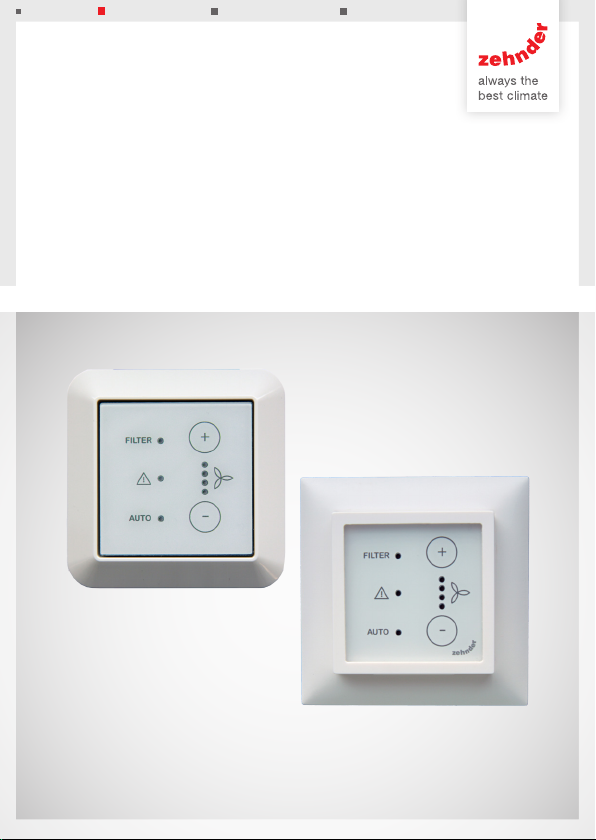
ComfoAir 70 / ComfoSpot 50
ComfoLED / ComfoLED CH
Montagehinweise - Installation notes - Instructions de montage - Indicazioni per
il montaggio - Montageaanwijzingen - Wskazówki dotyczące montażu
ComfoLED
ComfoLED CH
Page 2

Alle Rechte vorbehalten.
Die Zusammenstellung dieser Bedienungsanleitung erfolgte mit größter Sorgfalt. Dennoch
haftet der Herausgeber nicht für Schäden aufgrund von fehlenden oder nicht korrekten
Angaben in dieser Bedienungsanleitung. Bei Meinungsverschiedenheiten ist der deutsche
Originaltext letztendlich verbindlich.
All rights reserved.
This manual has been compiled with the utmost care. However, the publisher cannot be
held liable for any damage caused as a result of missing or incorrect information in this
manual. In case of disputes the German version of these instructions will be binding.
Tous droits reserves.
Ce manuel a ete compose avec le plus grand soin. L‘editeur ne peut neanmoins pas
etre tenu responsable de dommages decoulant d‘informations manquantes ou erronees
dans ce manuel. En cas de différend, seule la version allemand de ce mode d’emploi est
contraignante.
Tutti i diritti riservati.
La presente documentazione è stata redatta con la massima attenzione. L‘editore non
può comunque essere ritenuto responsabile di eventuali danni derivanti dalla mancanza o
dall‘inesattezza delle informazioni qui fornite. In caso di disaccordo, fa fede l‘originale in
lingua tedesca.
Alle rechten voorbehouden.
Bij de samenstelling van deze handleiding is uiterste zorg betracht, de uitgever kan echter
niet verantwoordelijk worden gehouden voor enige schade ontstaan door het ontbreken of
onjuist vermelden van informatie in deze handleiding. In geval van onenigheid is de Duitse
tekst leidend.
Wszelkie prawa zastrzeżone.
Niniejsza instrukcja obsługi została sporządzona z najwyższą starannością. Wydawca nie
ponosi odpowiedzialności za jakiekolwiek szkody powstałe na skutek nieumieszczenia w
niej informacji lub umieszczenia w niej nieprawidłowych informacji. W przypadku sporów
wiążąca jest wersja niniejszej instrukcji w języku niemiecki.
2
Page 3

Montageanleitung .............................................................................
4-7
Installation notes ...............................................................................
Instructions de montage ..................................................................
Indicazioni per il montaggio ...............................................................
Montageaanwijzingen .......................................................................
Wskazówki dotyczące montażu ........................................................
8-11
12-15
16-19
20-23
24-27
3
Page 4
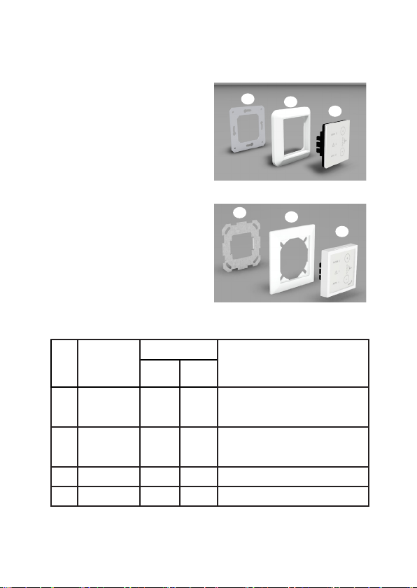
externe Bedieneinheit
Verwendungszweck
Die Comfo LED (ComfoLED CH)
bietet die Möglichkeit das Lüftungsgerät bequem aus der Ferne zu bedienen. Das Bedienteil ist
ausschließlich für eine Unterputzinstallation im Innenbereich in die
marktüblichen Schalterprogramme
geeignet und wird über ein maximal 25 m langes, 4-adriges Kabel
(z.B. Typ: J-Y(ST)Y 2x2x0,6) mit
dem Lüftungsgerät verbunden.
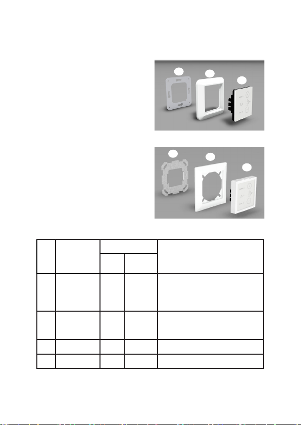
Lieferumfang
Pos Bezeichnung
Funktionseinheit
1
Blend-
2
rahmen
UP-Rahmen
3
Verbindungskabel
4
ComfoLED
x x
x x
x x
ComfoLED CH
Aufbau / Lieferumfang
3
ComfoLED
3
ComfoLED CH
bestehend aus: berührungssensitive Schaltäche,
Anschlussplatine mit Federzugklemmen und
Halteplatte mit Rastfüßen
Blendrahmen des Schalterprogramms muss
über ein Standardmaß von 55x55 mm zur
x
Aufnahme der Funktionseinheit verfügen
mit 4-pol. Steckverbinder (ohne Abbildung)
2
2
Bemerkung
1
1
Tab.1: Lieferumfang der externen Bedieneinheit
4
Page 5
externe Bedieneinheit
Funktionalität
Die Bedieneinheit verfügt über
berührungssensitive Schaltächen,
das heißt, durch Berühren der
betreffenden Tasten werden die
jeweiligen Bedienfunktionen
ausgelöst. Das Lüftungsgerät
kann gleichzeitig mit der internen
und der externen Bedieneinheit
betrieben werden. Dabei sind
die Tastenbelegungen und die
LED-Signalisierungen beider
Bedienteile funktional gleich.
Installation
Das Kabel und eine
UP-Schalterdose für
die externe Bedieneinheit sind
bauseits vorab zu installieren. Der
lüftungsgeräteseitige Anschluss des
Kabels für das externe Bedienteil
ist im Zuge mit dem Anschluss
der Spannungsversorgung
herzustellen.
Elektrischer Anschluss
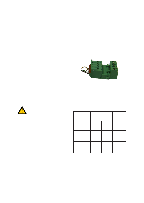
BUS X7 der Steuerungsplatine des
Lüftungsgerätes anzuschließen.
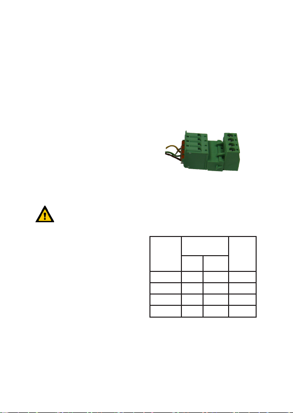
Das Bindeglied zwischen
Verbindungskabel und dem
bauseitigen Kabel zum externen
Bedienteil ist der 4-polige
Steckverbinder.
Die Adern des Kabels zum externen
Bedienteil sind beim Lüftungsgerät
am Steckverbinder mit den
Schraubklemmen anzuklemmen.
Farb-
codierung
Verbindungs-
kabel
weiß - -
gelb A A
grün B B
braun + +
Tab.2: Farbkodierungen
Steckverbinder
Verbindungskabel
Federzug-
Schraub-
klemme
klemme
Farb-
codierung
externe
BDE
Lüftungsgeräteseitig:
Die Adern des Verbindungskabels
sind entsprechend der Farbcodierung an die Klemmstelle
Bedienteilseitig:
Die Adern des Kabels sind
entsprechend der Farbcodierung an
die Federzugklemmen +, B, A, - der
5
Page 6
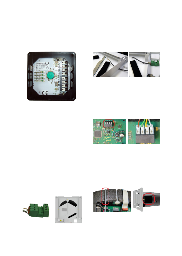
externe Bedieneinheit
Anschlussplatine der Bedieneinheit
anzuschließen. Dabei das Kabel
zuerst durch den Blendrahmen
führen!
Drücken Sie die Funktionseinheit
vorsichtig und lagerichtig mit
jeweils seitlicher Position der
Rastfüße in den UP-Rahmen bis
der Blendrahmen xiert ist.
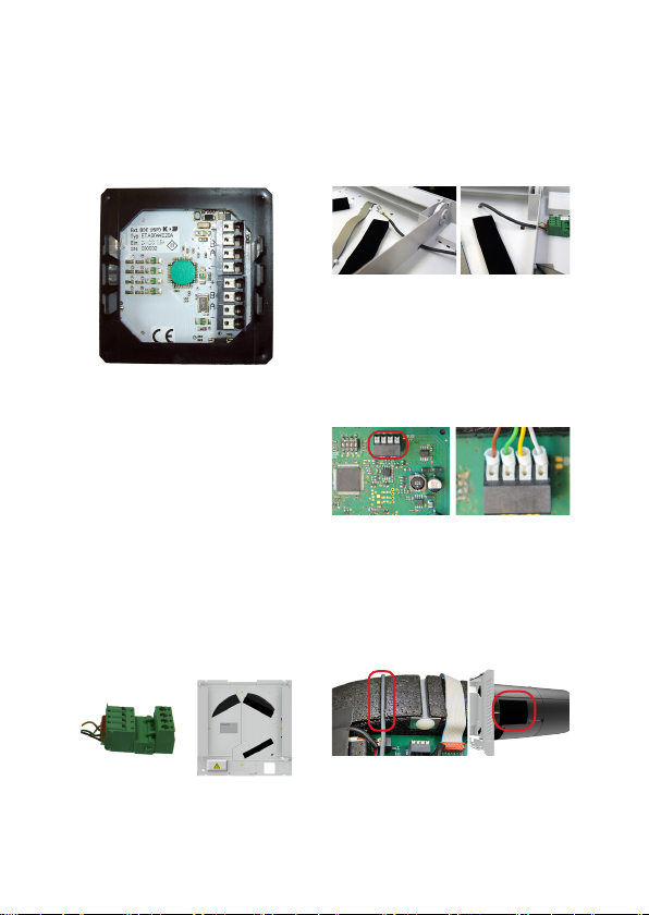
ComfoSpot 50
Ziehen Sie das Steckverbindungsteil
mit den Schraubklemmen ab
und klemmen Sie die Adern des
bauseitigen Kabels an. Notieren Sie
die Farbcodierung!
Führen Sie das Verbindungskabel
mit den Aderenden durch die
Öffnungen der Unterschale bis an
die Steuerungsplatine.
Klemmen Sie die Adern des Verbindungskabels gemäß Farbcodierung
an die Ferderzugklemmen BUS X7
der Steuerungsplatine an Gehäuse.
Verlegen Sie das
Verbindungskabel in der
vorgesehenen Kabelmulde des
EPP-Gehäuses und verschließen
Sie die Steuerungsplatine mit der
PVC-Abdeckung.
Stecken Sie nach Einschieben des
Gerätes in das Wandeinbaurohr die
beiden Teile des Steckverbinders
6
Page 7
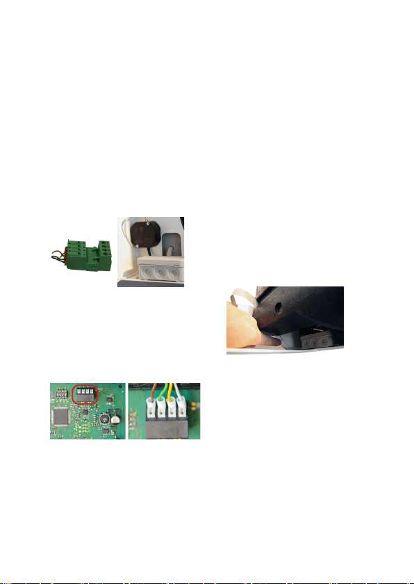
im Bereich der Kabeleinführung
zusammen.
ComfoAir 70
externe Bedieneinheit
Ziehen Sie das Steckverbindungsteil
mit den Schraubklemmen ab
und klemmen Sie die Adern des
bauseitigen Kabels an. Notieren Sie
die Farbcodierung!
Klemmen Sie die Adern
des Verbindungskabels
gemäß Farbcodierung an die
Ferderzugklemmen BUS X7 der
Steuerungsplatine an Gehäuse.
Stecken Sie die beiden Teile
des Steckverbinders zusammen
und verbringen Sie das
Verbindungskabel im elektrischen
Anschlussbereich des Gerätes.
Schieben Sie das Gerät unter
Beachtung der elektrischen
Anschlüsse bis zum Anschlag in
das Wandeinbaurohr.
7
Page 8
External control panel
Intended purpose
The Comfo LED (ComfoLED CH)
allows the ventilation unit to be
conveniently operated remotely.
The control panel is only suitable
for indoor in-wall installation in
conventional switch ranges and
is connected to the ventilation unit
with a 4-core cable with
a maximum length of 25 m
(e.g. type: J-Y(ST)Y 2x2x0.6).
Scope of delivery
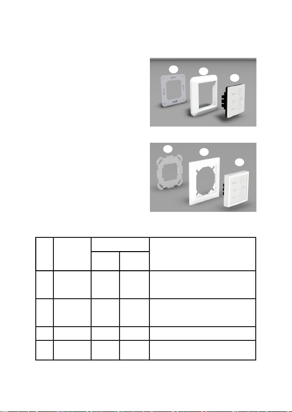
Item Description
1 Function unit x x
2 Cover frame x
3 In-wall frame x x
Connecting
4
cable
Tab.1: Scope of delivery of the external control panel
ComfoLED
ComfoLED CH
x x With 4-pin plug-in connector (not illustrated)
Design / Scope of
delivery
3
ComfoLED
3
ComfoLED CH
Consisting of: touch-sensitive button,
connection board with spring-type terminals
and retaining plate with snap-in feet
The cover frame of the switch range must
have standard dimensions of 55x55 mm
in order to hold the function unit
Note
2
2
1
1
8
Page 9
External control panel
Functionality
The control panel has touchsensitive buttons, which means the
respective operating functions are
triggered by touching the relevant
buttons. The ventilation unit can be
operated at the same time with the
internal and the external control
panel. The button assignments
and the LED signalling in both
control panels are identical in
terms of functions.
Installation
The cable and an in-wall
switch box for the external
control panel must be installed in
advance on site. On the ventilation
unit side, the cable connection for
the external control panel must
be established in the course of
connecting the power supply.
Electrical connection
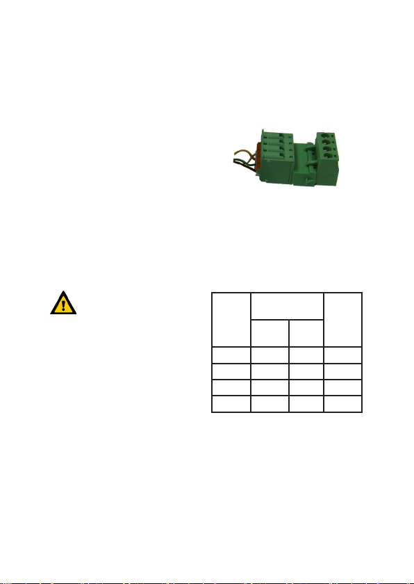
Ventilation unit side:
The wires of the connecting cable
are to be connected to the BUS X7
clamping point on the ventilation
unit control board according to
the colour coding.
The 4-pin plug-in connector is
the connecting link between the
connecting cable and the onsite cable for the external control
panel.
The wires of the cable for the
external control panel are to be
connected to the plug-in connector
with the screw-type terminals on
the ventilation unit.
Colour
Plug-in connector for
coding for
connecting cable
connecting
Spring-type
cable
terminal
White - -
Yellow A A
Green B B
Brown + +
Tab.2: Colour coding
Screw-type
terminal
Colour
coding
for external
PDA
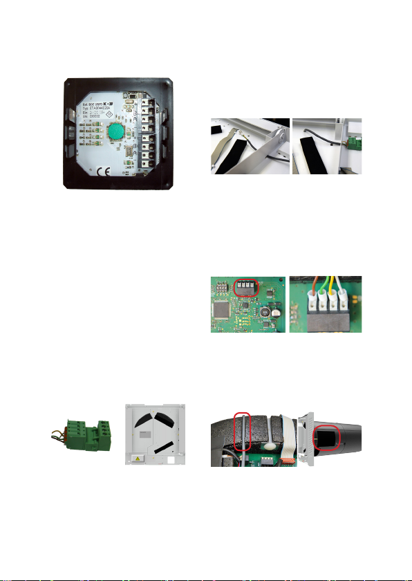
Control panel side:
The cable wires are to be
connected to the +, B, A, - springtype terminals on the control
panel connection board according
to the colour coding. Guide the
9
Page 10
External control panel
cable through the cover frame rst.
Carefully push the correctly
positioned function unit with the
snap-in feet in the lateral position
into the in-wall frame until the
cover frame is xed in place.
ComfoSpot 50
Disconnect the plug-in connector
part with the screw-type terminals
and connect the wires of the onsite cable. Make a note of the
colour coding.
Guide the connecting cable
with the wire ends through the
openings of the bottom cover to
the control board.
Connect the wires of the
connecting cable to the BUS
X7 spring-type terminals on the
control board according to the
colour coding.
Install the connecting cable in the
designated cable recess of the
EPP housing and close the control
board with the PVC cover.
After inserting the unit into the wall
mounting pipe, connect both parts
of the plug-in connector together
in the area of the cable entry point.
10
Page 11
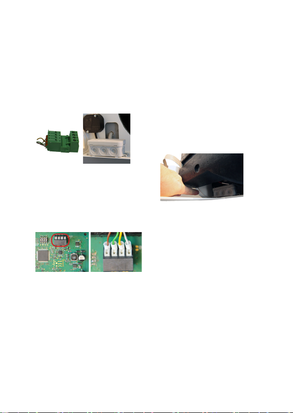
ComfoAir 70
External control panel
Disconnect the plug-in connector
part with the screw-type terminals
and connect the wires of the onsite cable. Make a note of the
colour coding.
Connect the wires of the
connecting cable to the BUS
X7 spring-type terminals on the
control board according to the
colour coding.
Connect both parts of the plug-in
connector together and pass the
connecting cable into the electrical
connection area of the unit.
Push the unit into the wall
mounting pipe as far as it will go,
taking into account the electrical
connections.
11
Page 12
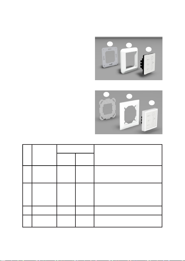
Interface de commande externe
Utilisation prévue
Structure / contenu de
la livraison
Le Comfo LED (ComfoLED CH)
permet une commande aisée de
l’appareil de ventilation à distance.
L’interface de commande est
exclusivement conçue pour une
installation encastrée en intérieur,
dans les gammes d’interrupteurs
courantes sur le marché. Elle
est raccordée à l’appareil de
ventilation au moyen d’un câble
à 4 conducteurs de 25 m de long
maximum (p. ex. du type :
J-Y(ST)Y 2 x 2 x 0,6).
Contenu de la livraison
Pos. Désignation
Unité fonction-
1
nelle
2 Cache x
3 Cadre encastré x x
Câble de
4
raccordement
Tab. 1 : Contenu de la livraison de l’interface de commande externe
ComfoLED
ComfoLED CH
x x
x x Avec connecteur 4 pôles (non représenté)
3
ComfoLED
3
ComfoLED CH
Comprend : surface tactile, platine de
raccordement avec bornes à ressort et
plaque de retenue avec pattes d’emboîtement
Le cache de la gamme d’interrupteurs
doit avoir des dimensions standard de
55 x 55 mm pour pouvoir accueillir l’unité
fonctionnelle
2
2
Remarque
1
1
12
Page 13
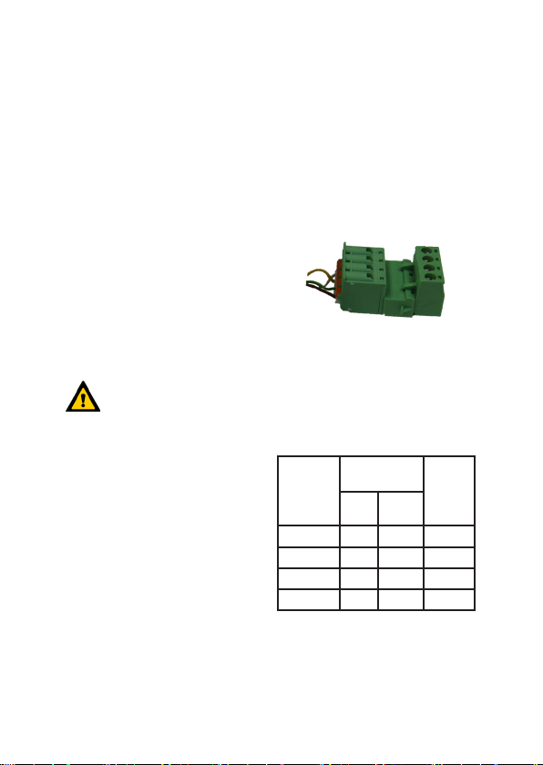
Interface de commande externe
Fonctionnalité
L’interface de commande dispose de
surfaces tactiles, si bien qu’il suft
d’efeurer les touches correspondantes
pour activer les fonctions associées.
L’appareil de ventilation peut être
commandé simultanément par
l’interface de commande interne et
l’interface de commande externe. Pour
ce faire, l’affectation des touches et
les signaux LED sont identiques sur le
plan fonctionnel sur les deux interfaces
de commande.
Installation
Le câble et un boîtier
d’interrupteur encastré
pour l’interface de commande
externe doivent avoir été installés
préalablement par le client. Le
raccordement, côté appareil de
ventilation, du câble pour l’interface
de commande externe doit s’effectuer
lors du raccordement à l’alimentation
électrique.
Raccordement électrique
Côté appareil de ventilation :
Les conducteurs du câble de
raccordement doivent être branchés
conformément aux codes couleur
au point de serrage BUS X7 de la
platine de commande de l’appareil de
ventilation.
Le connecteur 4 pôles sert d’élément
de liaison entre le câble de
raccordement et le câble fourni par le
client vers l’interface de commande
externe.
Les conducteurs du câble menant
à l’interface de commande externe
doivent être branchés au niveau de
l’appareil de ventilation au connecteur
avec les bornes à vis.
Code couleur,
câble de
raccordement
blanc - -
jaune A A
vert B B
marron + +
Tab. 2 : Codes couleur
Connecteur, câble de
raccordement
Borne à
Borne
ressort
à vis
Code
couleur
Interf. cde
externe
Côté interface de commande :
Les conducteurs du câble doivent
13
Page 14
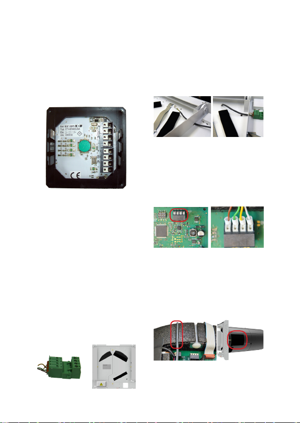
Interface de commande externe
être branchés conformément au code
couleur aux bornes à ressort +, B, A,
- de la platine de raccordement de
l’interface de commande. Le câble
doit tout d’abord être passé à travers
le cache !
Enfoncer avec précaution l’unité
fonctionnelle correctement
positionnée avec les pattes
d’emboîtement sur les côtés dans
le cadre encastré, jusqu’à ce que le
cache soit xé.
ComfoSpot 50
Retirer la partie du connecteur
avec les bornes à vis et brancher
les conducteurs du câble fourni
par le client. Attention au code
couleur !
Faire passer le câble de
raccordement avec les extrémités
des conducteurs à travers l’orice
de la coiffe inférieure jusqu’à la
platine de commande.
Serrer les conducteurs du câble
de raccordement, conformément
au code couleur, sur les bornes à
ressort BUS X7 de la platine de
commande.
Acheminer le câble de raccordement
dans la rainure de câble prévue à
cet effet du boîtier en EPP et fermer
la platine de commande avec le
couvercle en PVC.
Après avoir inséré l’appareil dans le
tube de montage mural, emboîter
14
Page 15
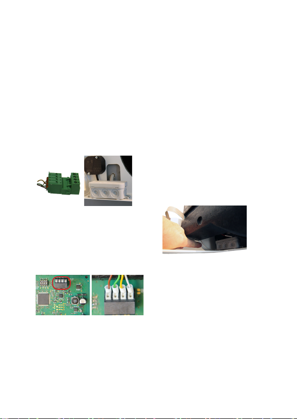
les deux parties du connecteur dans
la zone d’entrée de câble.
ComfoAir 70
Interface de commande externe
Retirer la partie du connecteur
avec les bornes à vis et brancher
les conducteurs du câble fourni
par le client. Attention au code
couleur !
Serrer les conducteurs du câble
de raccordement, conformément
au code couleur, sur les bornes à
ressort BUS X7 de la platine de
commande.
Emboîter les deux parties du
connecteur et amener le câble
de raccordement dans la zone
de raccordement électrique de
l’appareil.
Glisser l’appareil jusqu’à la
butée dans le tube de montage
mural en prêtant attention aux
raccordements électriques.
15
Page 16
Unità di comando esterna
Impiego previsto
Comfo LED (ComfoLED CH)
esterna offre la possibilità di
controllare comodamente
a distanza il dispositivo di
ventilazione. Il pannello di
comando è idoneo esclusivamente
all’installazione incassata all’interno
di gamme di interruttori comuni
e viene collegato al dispositivo di
ventilazione per mezzo di un cavo a
4 li di massimo 25 m di lunghezza
(ad es. del tipo J-Y(ST)Y 2x2x0,6).
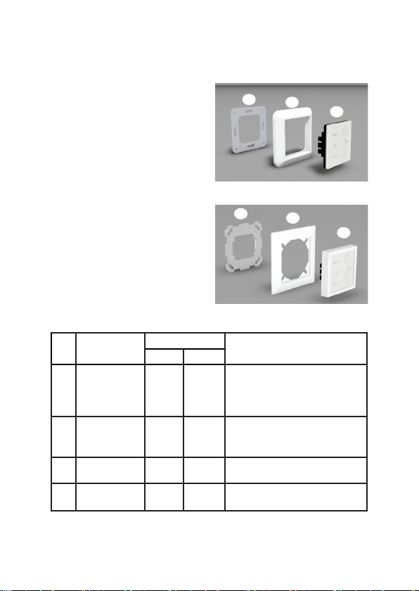
Pos. Denominazione
1 Unità funzionale x x
2 Cornice x
3 Telaio ad incasso x x
Cavo di
4
collegamento
Dotazione
ComfoLED
ComfoLED CH
x x Con connettore quadripolare (non illustrato)
Struttura / dotazione
3
ComfoLED
3
ComfoLED CH
Costituta da: supercie di contatto sensibile
al tatto, scheda elettronica con morsetti
a molla e piastra di supporto con piedini
a scatto
Per poter accogliere l’unità funzionale, la
cornice della gamma di interruttori deve
avere una misura standard di 55x55 mm
2
2
Osservazione
1
1
Tab. 1: dotazione dell’unità di comando esterna
16
Page 17
Unità di comando esterna
Funzionalità
L’unità di comando presenta
superci di contatto sensibili al tatto,
vale a dire che toccando determinati
pulsanti si attivano le rispettive
funzioni di comando. Il dispositivo
di ventilazione può essere utilizzato
contemporaneamente con l’unità
di comando interna e con quella
esterna. Dal punto di vista delle
funzioni, le assegnazioni dei pulsanti
e le segnalazioni dei LED dei due
pannelli di comando sono identiche.
Installazione
Il cavo e una scatola di
distribuzione ad incasso per
l’unità di comando esterna devono
essere predisposti dal cliente. Il
cavo per pannello di comando
esterno deve essere collegato al
dispositivo di ventilazione durante il
collegamento dell’alimentazione di
tensione.
Collegamento elettrico
dispositivo di ventilazione
secondo la codica colore.
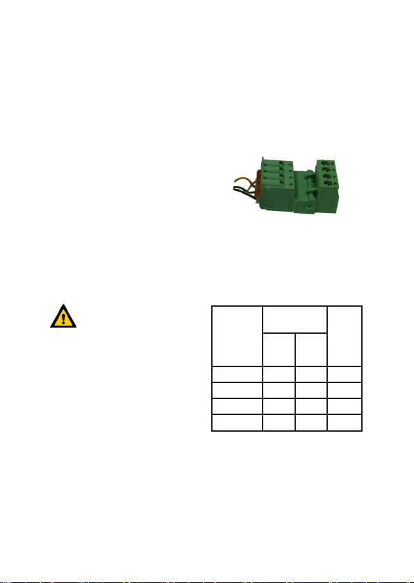
L’elemento di unione tra il cavo di
collegamento e il cavo del cliente
diretto al pannello di comando
esterno è il connettore quadripolare.
Nel dispositivo di ventilazione,
i li del cavo diretti al pannello di
comando esterno vanno ssati al
connettore con i morsetti a vite.
Codica
colore cavo di
collegamento
bianco - -
giallo A A
verde B B
marrone + +
Tab. 2: codiche colore
Connettore cavo
di collegamento
Morsetto
Morsetto
a molla
a vite
Codica
colore
Unità di
comando
esterna
Lato del dispositivo di ventilazione:
I li del cavo di collegamento vanno
allacciati alla morsettiera BUS
X7 della scheda di comando del
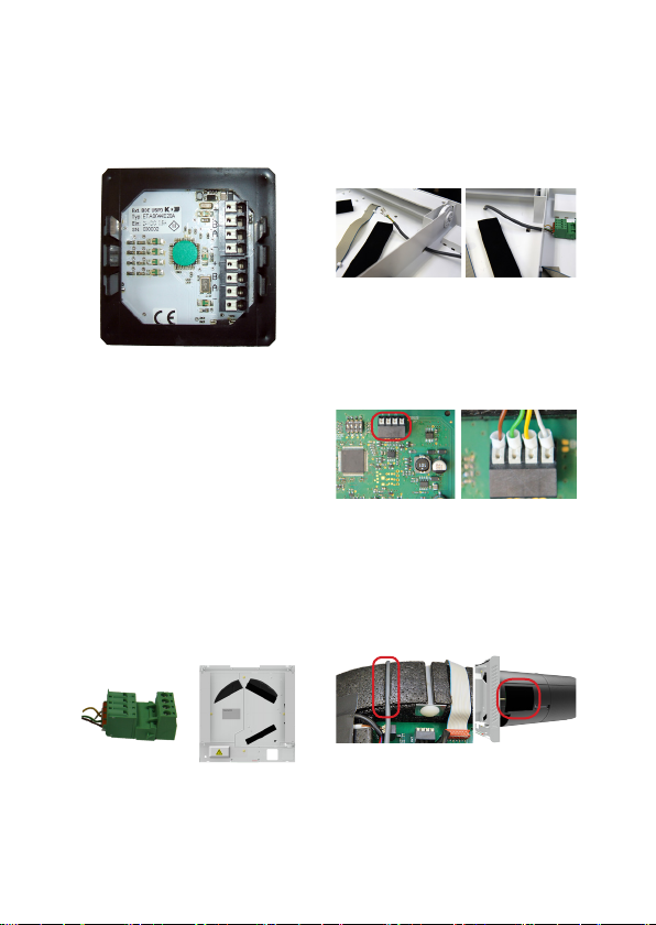
Lato del pannello di comando:
i li del cavo vanno collegati ai
morsetti a molla +, B, A, - della
scheda elettronica dell’unità
17
Page 18
Unità di comando esterna
di comando secondo la codica
colore. Per prima cosa far passare
il cavo attraverso la cornice!
Premere con cautela l’unità
funzionale nel telaio ad incasso
mantenendo la posizione corretta
rispetto alla posizione dei piedini a
scatto, no a ssare la cornice.
ComfoSpot 50
Estrarre la parte del connettore
con i morsetti a vite e ssare i li
del cavo del cliente. Prendere nota
della codica colore!
Introdurre il cavo di collegamento
nelle aperture del rivestimento
inferiore, no alla scheda di
comando.
Fissare i li del cavo di collegamento
ai morsetti a molla BUS X7 della
scheda di comando rispettando la
codica colore.
Posare il cavo di collegamento
nella scanalatura prevista
dell’alloggiamento in EPP e
chiudere la scheda di comando
con il coperchio di PVC.
Dopo aver inserito il dispositivo
nel tubo per montaggio a parete,
unire i due pezzi del connettore
18
Page 19
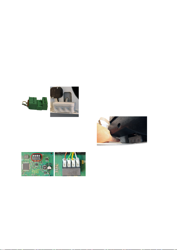
in corrispondenza del punto di
introduzione del cavo.
ComfoAir 70
Unità di comando esterna
Estrarre la parte del connettore
con i morsetti a vite e ssare i li
del cavo predisposti. Prendere no-
ta della codica colore!
Fissare i li del cavo di
collegamento ai morsetti a molla
BUS X7 della scheda di comando
rispettando la codica colore.
Unire i due pezzi del connettore
e portare il cavo di collegamento
nella zona di attacco elettrico del
dispositivo.
Inserire il dispositivo nel tubo
per montaggio a parete no alla
battuta, facendo attenzione ai
collegamenti elettrici.
19
Page 20
externe bedieningsunit
Gebruiksdoel
Met de Comfo LED (ComfoLED
CH) kan de ventilatie-unit
comfortabel op afstand worden
bediend. De bedieningsunit
is uitsluitend geschikt
voor inbouwinstallatie in
binnentoepassingen in gangbare
schakelaarprogramma's en wordt
via een maximaal 25 m lange
kabel met 4 aders (bijv. type:
J-Y(ST)Y 2x2x0,6) verbonden met
de ventilatie-unit.
Levering
Pos Aanduiding
Functie-eenheid
1
Afdekframe
2
3 Inbouwframe x x
4 Verbindingskabel x x
ComfoLED
x x
ComfoLED CH
Opbouw /
leveringsomvang
3
ComfoLED
3
ComfoLED CH
bestaande uit: aanrakingsgevoelige
schermknop, aansluitprintplaat met
veerklemmen en vasthoudplaat met
vergrendelvoeten
Afdekframe van het schakelaarprogramma
moet over een standaardmaat van 55x55 mm
x
beschikken om de functie-unit op te nemen
met 4-polige steekverbinding (niet afgebeeld)
2
2
Opmerking
1
1
Tab.1: Leveringsomvang van de externe bedieningsunit
20
Page 21
externe bedieningsunit
Functionaliteit
De bedieningsunit beschikt over
aanrakingsgevoelige schermknoppen,
wat inhoudt dat de diverse
bedieningsfuncties door aanraking
van de bijbehorende knoppen in gang
worden gezet. De ventilatie-unit kan
tegelijkertijd met de interne en de externe
bedieningsunit worden aangestuurd.
Daarbij zijn de toetsbezettingen
en de LED-indicaties van beide
bedieningsunits functioneel gelijk.
Installatie
De kabel en een
inbouwschakelaardoos voor
de externe bedieningsunit moeten ter
plekke vooraf worden geïnstalleerd. De
aansluiting van de kabel aan ventilatieunitzijde voor de externe bedieningsunit
moet in het kader van de aansluiting van
de voedingsspanning tot stand worden
gebracht.
Elektrische aansluiting
Ventilatie-unitzijde:
De aders van de verbindingskabel
moeten overeenkomstig de kleurcodering op de klem
BUS X7 van de besturingsprintplaat
van de ventilatie-unit worden
aangesloten.
Het verbindingselement tussen de
verbindingskabel en de ter plekke door
de opdrachtgever beschikbaar te stellen
kabel naar de externe bedieningsunit is
de 4-polige stekkerverbinding.
De aders van de kabel naar de
externe bedieningsunit moeten op de
ventilatie-unit op de insteekverbinding
met de schroefklemmen worden
aangesloten.
Kleurcodering
verbindingskabel
wit
geel A A
groen B B
bruin
Tab.2: Kleurcoderingen
Steekverbinding
verbindingskabel
Veerklem Schroefklem
- -
+ +
Kleurcodering
externe
bediening
Bedieningsunitzijde:
De aders van de kabel moeten
overeenkomstig de kleurcodering
21
Page 22
externe bedieningsunit
worden aangesloten op de veerklemmen
+, B, A, - van de aansluitprintplaat van
de bedieningsunit. De kabel moet eerst
door het afdekframe worden gevoerd!
Duw terwijl de vergrendelvoeten zijdelings gepositioneerd zijn, de functie-unit voorzichtig en in de juiste positie in het inbouwframe tot het afdekframe vastzit.
ComfoSpot 50
Trek het insteekverbindingsdeel met
de schroefklemmen af en sluit de
aders van de ter plekke te leveren
kabel aan. Noteer de kleurcodering!
Voer de verbindingskabel met
de adereinden door de openingen
van de onderschaal naar de
besturingsprintplaat.
Sluit de aders van de
verbindingskabel overeenkomstig
de kleurcodering aan op de
veerklemmen BUS X7 van de
besturingsprintplaat.
Plaats de verbindingskabel in de
daarvoor bestemde kabelgoot
van de EPP-behuizing en sluit
de besturingsprintplaat af met de
PVC-afdekking.
Steek, nadat u het apparaat in
de mantelbuis heeft geschoven,
de beide delen van de
22
Page 23
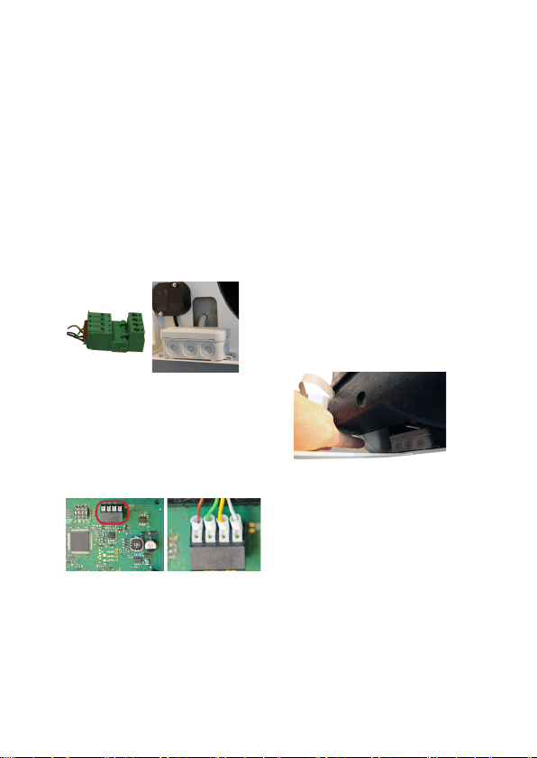
insteekverbinding ter hoogte van
de kabelinvoer in elkaar.
ComfoAir 70
externe bedieningsunit
Trek het insteekverbindingsdeel
met de schroefklemmen af en
sluit de aders van de ter plekke
te leveren kabel aan. Noteer de
kleurcodering!
Sluit de aders van de
verbindingskabel overeenkomstig
de kleurcodering aan op de
veerklemmen BUS X7 van de
besturingsprintplaat.
Steek de beide delen van de
insteekverbinding in elkaar en
plaats de verbindingskabel in het
elektrisch aansluitgedeelte van het
apparaat.
Schuif het apparaat met
inachtneming van de elektrische
aansluitingen tot aan de aanslag in
de mantelbuis.
23
Page 24
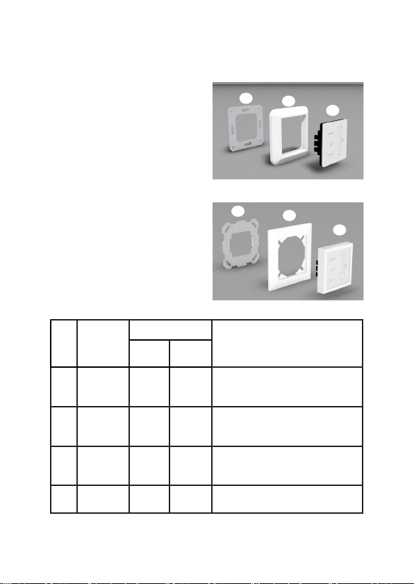
Zewnętrzny panel sterowania
Przeznaczenie
Comfo LED (ComfoLED CH)
umożliwia wygodną i zdalną
obsługę centrali wentylacyjnej.
Panel sterowania jest przeznaczony
wyłącznie do instalacji
podtynkowych, przeznaczonych
dla dostępnych na rynku modułów
przełączników i montowanych we
wnętrzach, oraz jest połączony
z centralą wentylacyjną 4-żyłowym
kablem o długości maksymalnie
25 m (np. typu: J-Y(ST)Y 2x2x0,6).
Zakres dostawy
Poz. Nazwa
Jednostka
1
funkcyjna
Ramka
2
osłaniająca
Podtynkowa
3
konsola
montażowa
Kabel
4
łączący
Tab.1: Zakres dostawy zewnętrznego panelu sterowania
ComfoLED
ComfoLED CH
x x
x
x x
x x Z 4-stykowym złączem wtykowym (bez rysunku)
Budowa / zakres
dostawy
3
ComfoLED
3
ComfoLED CH
Składająca się z: przycisku dotykowego,
płyty montażowej z zaciskami śrubowymi
i płyty mocującej z nóżkami blokującymi
Ramka osłaniająca moduł przełączników
musi mieć standardowy wymiar 55x55 mm
i służy do mocowania jednostki funkcyjnej
2
2
Uwagi
1
1
24
Page 25

Zewnętrzny panel sterowania
Działanie
Panel sterowania posiada dotykowe
przyciski, co oznacza, że dotknięcie
dowolnego przycisku powoduje
aktywację odpowiedniej funkcji
obsługowej. Centrala wentylacyjna
może być jednocześnie obsługiwana
za pośrednictwem wewnętrznego
i zewnętrznego panelu sterowania.
Przyporządkowania przycisków
i diody sygnalizacyjne LED obu
paneli działają wówczas w taki sam
sposób.
Instalacja
Kabel i podtynkowa puszka
montażowa zewnętrznego
panelu sterowania muszą zostać
wcześniej zainstalowane przez
inwestora. Przyłącze kabla po
stronie centrali wentylacyjnej
prowadzącego do zewnętrznego
panelu sterownia należy podłączyć
do sieci elektrycznej.
Zasilanie elektryczne
Po stronie centrali wentylacyjnej:
Żyły kabla łączącego należy
wpiąć zgodnie z kodem
kolorów do zacisków BUS X7
centrali wentylacyjnej.
Elementem połączeniowym
kabla łączącego z przewodem
sterującym prowadzącym do
zewnętrznego panelu jest
4-stykowe złącze wtykowe.
Żyły przewodu sterującego
zewnętrznego panelu sterowania,
należy podłączyć do złącza
wtykowego z zaciskami śrubowymi
w centrali wentylacyjnej.
Kod
Złącze wtykowe kabla
łączącego
kolorów
kabla
Zacisk
łączącego
sprężynowy
biały - -
żółty A A
zielony B B
brązowy + +
Tab.2: Kody kolorów
Zacisk
śrubowy
Kod
kolorów
Zewn.
panel
sterowania
Po stronie panelu sterowania:
Żyły kabla należy podłączyć
25
Page 26
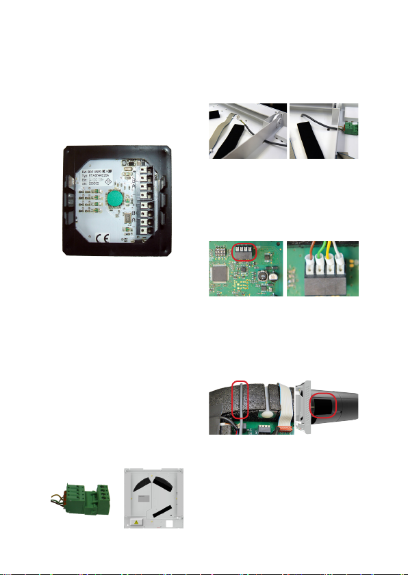
Zewnętrzny panel sterowania
zgodnie z kodem kolorów do
zacisków sprężynowych +, B,
A, - płytki montażowej panelu
sterowania. Najpierw należy
poprowadzić kabel przez ramkę
osłaniającą!
Ostrożnie wsunąć panel sterujący
z prawidłowo ustawionymi po
bokach nóżkami blokującymi w
podtynkową puszkę montażową
aż do zamocowania ramki
osłaniającej.
ComfoSpot 50
Odłączyć element złącza
wtykowego z zaciskami śrubowymi
i podłączyć żyły kabla w miejscu
montażu. Zapisać kod kolorów!
Poprowadzić kabel łączący z
końcówkami żył przez otwory w
dolnej części aż do płytki sterującej.
Podłączyć żyły kabla łączącego
zgodnie z kodem kolorów do
zacisków sprężynowych BUS X7
płytki sterującej.
Ułożyć kabel łączący w
odpowiedniej rynience kablowej
obudowy EPP i zasłonić płytkę
sterującą osłoną z PVC.
Po wsunięciu urządzenia w otwór
w ścianie połączyć ze sobą obie
części złącza wtykowego w
obszarze prowadnicy kablowej.
26
Page 27
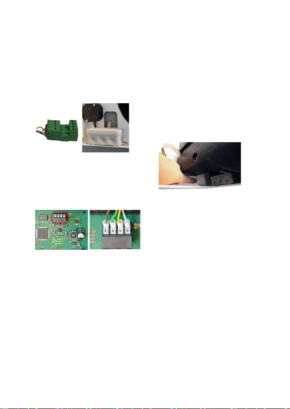
ComfoAir 70
Zewnętrzny panel sterowania
Odłączyć element złącza
wtykowego z zaciskami śrubowymi
i podłączyć żyły kabla w miejscu
montażu. Zapisać kod kolorów!
Podłączyć żyły kabla łączącego
zgodnie z kodem kolorów do
zacisków sprężynowych BUS X7
płytki sterującej.
Połączyć ze sobą obie części
złącza wtykowego i ułożyć kabel
łączący w obszarze przyłączy
elektrycznych urządzenia.
Wsunąć urządzenie do oporu w
otwór w ścianie z uwzględnieniem
przyłączy elektrycznych.
27
Page 28

Deutschland
Zehnder Group Deutschland
GmbH
Almweg 34
77933 Lahr
T +49 7821 586 0
F +49 7821 586 223
[email protected]
www.zehnder-systems.de
France
Zehnder Group France
3 rue du Bois Briard
91080 Courcouronnes
T +33 169 361 646
F +33 169 474 581
comfosystems.france@zehn-
dergroup.com
www.comfosystems.fr
The Netherlands
Zehnder Group Nederland B.V.
Lingenstraat 2
8028 PM Zwolle
T +31 38 42 96 911
F +31 38 42 25 694
[email protected]
www.jestorkair.nl
Great Britain
Zehnder Comfosystems UK Ltd
Unit 1, Brookside Avenue
Rustington West Sussex
BN16 3LF
T +44 1903 777 333
F +44 1903 782 398
[email protected]
www.zehnder.co.uk
United States
Zehnder America Inc.
540 Portsmouth Avenue
Greenland, NH 03840
T +1 603 422 6700
F +1 603 422 9611
[email protected]
www.zehnderamerica.com
Italy
Zehnder Tecnosystems S.r.l.
Via XXV Luglio, 6
Campogalliano (MO) 41011
T +39 059 978 62 00
F +39 059 978 62 01
[email protected]
www.comfosystems.it
Switzerland
Zehnder Comfosystems
Cesovent AG
Zugerstrasse 162
8820 Wädenswil
T +41 43 833 20 20
F +41 43 833 20 21
[email protected]
www.zehnder-comfosystems.ch
Poland
Zehnder Polska Sp. z o.o.
ul. Kurpiów 14a
52-214 Wrocław
T +48 71 367 64 24
F +48 71 367 64 25
[email protected]
www.zehnder.pl
Sales International
Zehnder Group Deutschland
GmbH
Almweg 34
77933 Lahr
Deutschland
T +49 7821 586-392
F +49 7821 586-406
sales.international@zehndergroup.com
www.international.zehndersystems.com
PDE-Installation Notes_CS50/CA70_Comfo LED/ComfoLED CH_V1.0,V1217_DE,EN,FR,IT,NL,PL_subject to change
 Loading...