

Page 1
™
ZyPer4K
CONFIGURATION GUIDE
Page 2
INSTRUCTIONS PERTAINING TO A RISK OF FIRE, ELECTRIC SHOCK, OR INJURY TO PERSONS
Important Safety Instructions. Save These Instructions.
WARNING: When using electronic products, basic precautions should always be followed, including:
1. Keep these instructions.
2. Heed all warnings.
3. Follow all instructions.
4. Do not use this apparatus near water.
5. Clean only with dry cloth.
6. Do not block any ventilation openings. Install in accordance with the
manufacturer’s instructions.
7. Do not install near any heat sources such as radiators, heat registers,
stoves, or other apparatus (including
ampliers) that produce heat.
8. Do not defeat the safety purpose of the polarized or grounding-type
plug. A polarized plug has two blades with one wider than the other.
A grounding type plug has two blades and a third grounding prong.
The wide blade or the third prong is provided for your safety. If the
provided plug does not t into your outlet, consult an electrician for
replacement of the obsolete outlet.
FCC Statement
FCC Compliance and Advisory Statement: This hardware device complies with Part 15 of the FCC rules.
Operation is subject to the following two conditions: 1) this device may not cause harmful interference, and 2) this device must accept any interference received including interference that may cause
CAUTION: TO REDUCE THE RISK OF ELECTRIC SHOCK
DO NOT REMOVE THE COVER (OR BACK).
NO USER SERVICABLE PARTS INSIDE.
REFER SERVICING TO QUALIFIED SERVICE PERSONNEL.
The lightning ash with arrowhead symbol, within an
equilateral triangle, is intended to alert the user to the
presence of uninsulated “dangerous voltage” within the product’s enclosure that may be of sufcient
magnitude to constitute a risk to persons.
The exclamation point within an equilateral triangle is
intended to alert the user to the presence of important
operating and maintenance (servicing) instructions in
the literature accompanying the product.
undesired operation. This equipment has been tested and found to comply with the limits for a Class
A digital device, pursuant to Part 15 of the FCC Rules. These limits are designed to provide reasonable
protection against harmful interference in a commercial installation. This equipment generates, uses,
and can radiate radio frequency energy and, if not installed or used in accordance with the instructions,
may cause harmful interference to radio communications. However there is no guarantee that interference will not occur in a particular installation. If this equipment does cause harmful interference to
radio or television reception, which can be determined by turning the equipment off and on, the user is
encouraged to try to correct the interference by one or more of the following measures: 1) reorient or
relocate the receiving antenna; 2) increase the separation between the equipment and the receiver; 3)
connect the equipment to an outlet on a circuit different from that to which the receiver is connected;
4) consult the dealer or an experienced radio/TV technician for help. Any changes or modications not
expressly approved by the party responsible for compliance could void the user’s authority to operate
the equipment. Where shielded interface cables have been provided with the product or specied additional components or accessories elsewhere dened to be used with the installation of the product,
they must be used in order to ensure compliance with FCC regulations.
9. Power cord must be accessible to allow for the removal of power
from the unit.
10. Protect the power cord from being walked on or pinched, particularly
at plugs, convenience receptacles, and the point where they exit from
the apparatus.
11. Unplug the apparatus during lightning storms or when unused for
long periods of time.
12. Only use attachments/accessories specied by the manufacturer.
13. Refer all servicing to qualied service personnel. Servicing is required
when the apparatus has been damaged in any way, such as powersupply cord or plug is damaged, liquid has been spilled or objects
have fallen into the apparatus, the apparatus has been exposed to
rain or moisture, does not operate normally, or has been dropped.
14. WARNING: To reduce the risk of re or electric shock do not
place this apparatus in a position where it is exposed to dripping
or splashing liquids, rain, moisture, or excessively high humidity.
Objects containing liquid shall not be placed in proximity to the unit
such that they present a risk of spillage onto the apparatus.
Page 2 | ZyPer4K Configuration Guide www.zeevee.com
Page 3

Conguring ZyPer4K
Table of Contents
ZyPer4K™ supports the distribution of ultra high-denition,
uncompressed video, audio and other data signals using off-the-shelf
10Gb Ethernet switching technology.
This guide will take you through setting up ZyPer4K in the following
environments:
• Point to Point (or one to one environment)
• Many to Many (or a switched environment)
Before setting up the system in your environment, ensure that all
sources and displays are HDMI compatible.
What ships in the box:
• ZyPer4K Encoder (Z4KENC-F1) orZyPer4K Decoder (Z4KDEC-F1)
(Encoders and Decoders are sold and shipped separately. At least one ZyPer4K
Encoder and one ZyPer4K Decoder are required.)
• Power supply (with local plug options)
Available separately (but needed to connect sources and displays):
Front and Back Panels ..........4
Setting Up ZyPer4K in a
Point to Point Environment ......5
Setting Up ZyPer4K in a
Many to Many Environment .....6
Installing ZyPer4K Management
Software ......................7
Connecting Encoders to
the 10Gb Network Switch .......8
Connecting Decoders to
the 10Gb Network Switch .......9
Conguring Encoder
and Decoder Options ..........10
Switching (Routing) Video
on your System ...............11
Using the Tabs in ZyPer4K
Management Software ...... 12-13
• SFP+ modules (available for order from ZeeVee)
• HDMI cables
• Fiber optic patch cables
• 10Gb network switch with IGMP Snooping capability
Additional Connections ........14
Warranty .....................15
Contact ZeeVee ...............16
ZyPer4K Configuration Guide | Page 3
Page 4
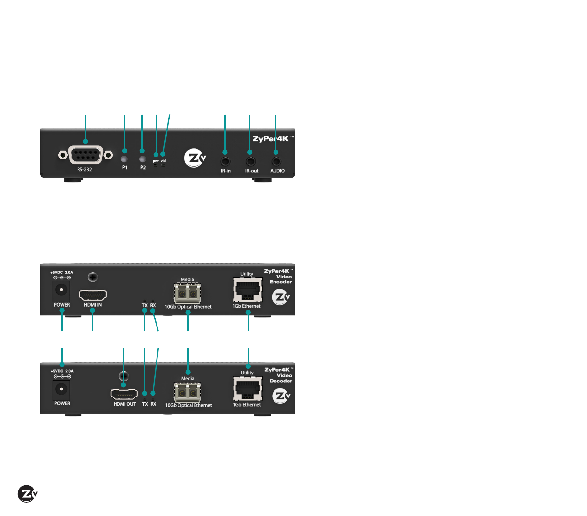
Front and Back Panels
A B C DE F G H
FRONT PANEL — ENCODER AND DECODER
BACK PANEL — ENCODER
I L M N OKJ
BACK PANEL — DECODER
FRONT PANELS
A RS-232 – Port used to connect to and control
peripherals (STB, Blu-ray, projector)
B P1 – Not used currently
C P2 – Pushes EDID information from connected
display to all connected Encoders. Resets to
the factory default settings. Press button for 10
seconds while powering up to revert back to
default factory settings.
D Pwr – Indicates when power is turned on
E Vid – Indicates when video is present in the unit
F IR-in – Infrared receiver-in port used to receive IR
signals (for example, from a user with a remote
control)
G IR-out – Infrared receiver-out port used to connect
to and control peripherals
H AUDIO – Audio connector for analog audio use
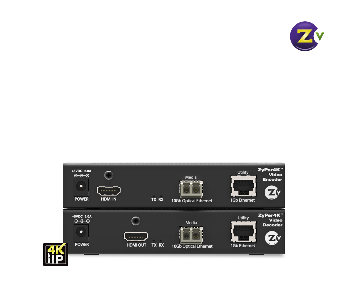
BACK PANELS
I POWER – 5V DC power input port
J HDMI IN – (Encoder only) Indicates HDMI-in cable
port
K HDMI OUT – (Decoder only) Indicates HDMI-out
cable port
L TX – Flashes when system is operating and data is
being transmitted across ber link
M RX – Flashes when system is operating and data is
being received across ber link
N Media/10Gb Ethernet – Slot for SFP+ Fiber Optic
Module (available from ZeeVee)
O Utility/1Gb Ethernet – Network port for
connection of local Ethernet device into network
Page 4 | ZyPer4K Configuration Guide www.zeevee.com
Page 5
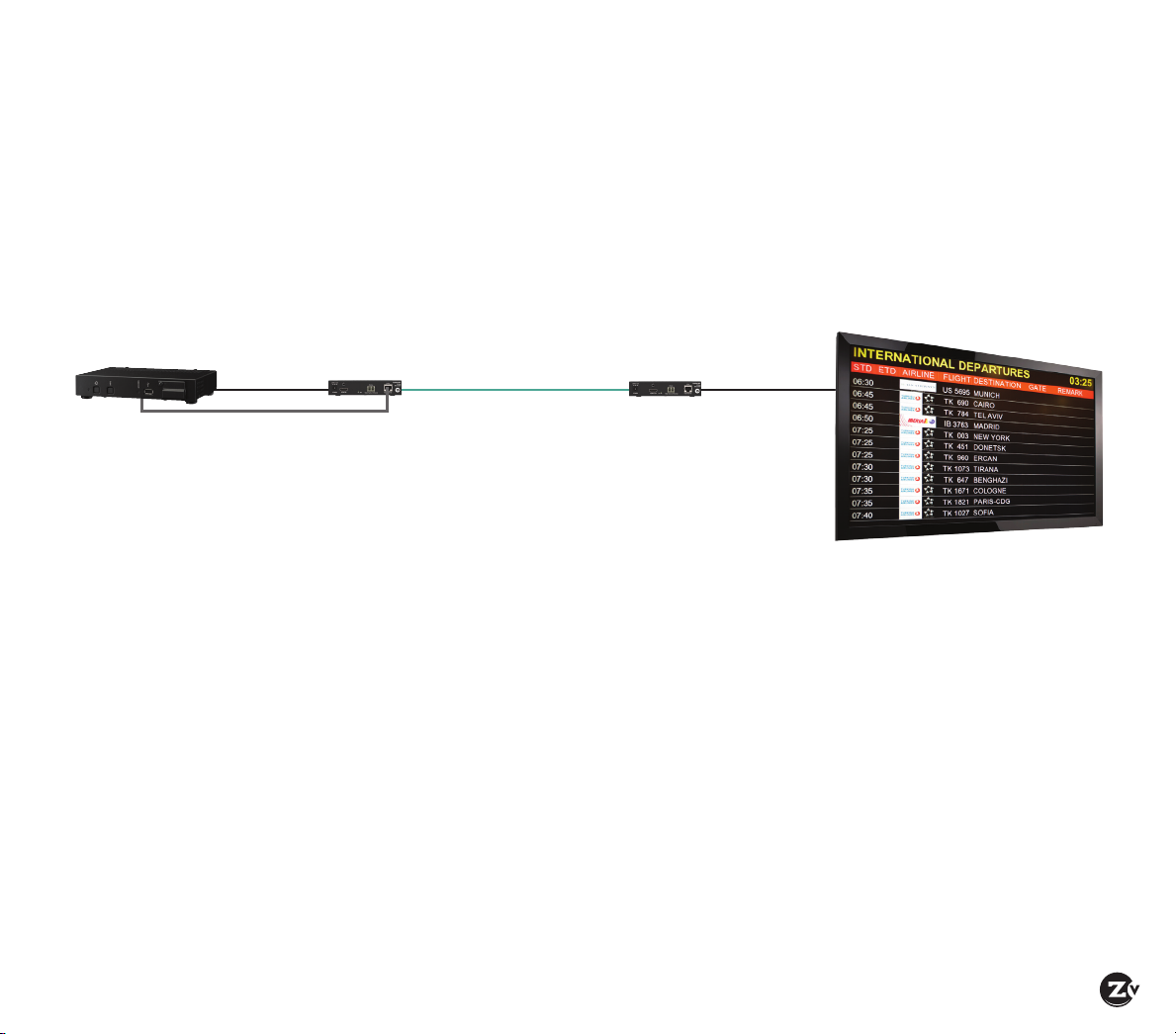
Setting Up ZyPer4K in a Point to Point Environment
A point to point, or one to one environment involves connecting one source directly to one display. A network
switch is not needed in this basic conguration. This environment also does not require conguration through
the ZyPer4K management software and is a true “plug and play” setup.
If using analog audio, RS232 or Infrared, you may need to congure the Encoder and Decoder with our
management software. See the Using the Tabs in ZyPer4K Management Software section for more information.
Digital Signage
Player
HDMI
ZyPer4K Encoder ZyPer4K Decoder
1. Connect HDMI cable from active source to Encoder (HDMI In port). Ensure Encoder is plugged
in and pwr LED light is illuminated. When HDMI cable is connected, the video (vid) light will
illuminate.
2. Insert SFP+ module into the 10Gb Optical Ethernet port on the Encoder. You should hear a
click sound when it is correctly inserted.
3. Insert ber optic cable into the SFP+ module. Again, you should hear a click sound when fully
inserted.
4. Connect HDMI cable from active display to Decoder (HDMI Out port). Ensure Decoder is
plugged in and that pwr LED light is illuminated.
5. Insert SFP+ module into the 10Gb Optical Ethernet port on the Decoder. You should hear a
click sound when it is correctly inserted.
6. Connect ber optic cable from the Encoder into the SFP+ module on the Decoder. Again, you
should hear a click sound when correctly inserted. The vid light on the Decoder will illuminate
and video coming from the source now appears on the display.
Point to Point
Fiber Connection
(up to 30km)
HDMI
ZyPer4K Configuration Guide | Page 5
Page 6

Setting Up ZyPer4K in a Many to Many Environment
A many to many, or switched environment involves connecting many sources to many displays.
ZyPer4K allows you a exible and scalable amount of input-output options without limitations.
For example, in a 24-port conguration, you can congure a 1x23, 6x18, or 4x20 (and so on) system.
A network switch is needed in these many to many congurations. These environments also require
conguration through the ZyPer4K management software.
Media Players
(Airshow)
(Wildlife)
Blu-Ray Player
Laptop
ZyPer4K Encoders
HDMI
HDMI
Software Management Platform
(required)
HDMI
IR
HDMI
1Gb Ethernet
To set up ZyPer4K in a many to many environment, you have to:
• Install ZyPer4K management software
• Connect all Encoders and Decoders to the 10Gb network switch
• Switch (or route) video from sources to displays
Fiber
Multi-Mode
ZyPer4K Decoders
10 GigaBit Ethernet
Fiber Switch
HDMI
HDTVs
RS-232
HDMI
RS-232
Page 6 | ZyPer4K Configuration Guide www.zeevee.com
Page 7

Installing ZyPer4K Management Software
ZyPer4K management software is available from ZeeVee technical support.
If presented with a Windows security dialog
box, ensure that both private and public
networks are checked and click Allow.
The telnet dialog box will then appear.
Click OK and the management software
opens.
This software refreshes every 5 seconds.
Note: The PC running the software has to be connected to the same network as the Encoders/Decoders.
Typically, you could use any available Ethernet port in your network switch, but you could also use any
available Utility Ethernet port on any connected Encoder/Decoder.
ZyPer4K Configuration Guide | Page 7
Page 8

Connecting Encoders to the 10Gb Network Switch
1. Connect HDMI cable from active source to Encoder (HDMI In port). Ensure Encoder is plugged in and pwr
LED light is illuminated. When HDMI cable is connected, the video (vid) light will illuminate.
2. Insert SFP+ module into the 10Gb Optical Ethernet port on the Encoder. You should hear a click sound
when it is correctly inserted.
3. Insert ber optic cable into the SFP+ module. Again, you should hear a click sound when correctly inserted.
4. Connect ber optic cable from the Encoder into any available 10Gb ber port on your 10Gb switch (IGMP
compatible). Ensure port has SFP+ module. You should hear a click sound when correctly inserted and the
activity link light on the 10Gb switch will blink. Encoder icon now appears in management software.
5. Right click on Encoder icon and choose Settings to congure Encoder options. Please refer to Conguring
Encoder/Decoder Options on page 10 for more detail.
6. Add additional Encoders using the steps above. Note: it does not matter what order you connect Encoders
or Decoders. For the purpose of this documentation, Encoder connection is presented rst.
Name of device
Current IP address
assigned to device
Firmware version details
Multi-cast address
(or channel #) for
the video on device
Video resolution
of the device
Page 8 | ZyPer4K Configuration Guide www.zeevee.com
Page 9

Connecting Decoders to the 10Gb Network Switch
1. Connect HDMI cable from active display to Decoder (HDMI Out port). Ensure Decoder is plugged in and LED light is
on. When HDMI cable is connected, the video (vid) light will illuminate.
2. Insert SFP + module into the 10Gb Optical Ethernet port on the Decoder. You should hear a click sound when it’s
fully inserted.
3. Insert ber optic cable into the SFP+ module on Decoder. Again, you should hear a click sound when fully inserted.
4. Connect ber optic cable from the Decoder into the 10Gb ber port on your 10Gb switch (IGMP compatible). Ensure
port has SFP+ module. You should hear a click sound when fully inserted and the activity link light on the 10Gb
switch will blink. The VID light on the Decoder will illuminate when the ber link is established between Encoder
(with active source plugged in) and Decoder. Decoder icon now appears in management software.
5. Right click on Decoder icon and choose Settings to congure Decoder options. Please refer to Conguring Encoder/
Decoder options on page 10 for more detail.
6. Add additional Decoders using the steps above.
Name of device
Current IP address
assigned to device
Firmware version details
Decoder details
ZyPer4K Configuration Guide | Page 9
Page 10

Conguring Encoder and Decoder Options
For ease of switching, you should dene a name for each device. You can also make other congurations
(such as IP address and RS232) for your Encoder and Decoder.
To dene Encoder and Decoder settings:
1. Right click on Encoder or Decoder icon and highlight the Settings option. The MAC address of the Encoder
or Decoder appears at the top of screen. (You must dene Encoder and Decoder settings separately.)
2. After making changes, click Save and then Exit.
Hostname – name
device something that
reects the source or
display connected,
for example, “Blu-ray
Player1” or “Conference
room right.” Naming the
display is particularly
useful if using the Video
Wall feature.
Note – there is a 20
character limit and
special characters
should be avoided as
they may not display.
IP – Select the IP addressing scheme. DHCP
dynamically assigns an IP address to the device.
The Manual setting allows you to set a static IP
address, network and gateway. Note – if DHCP
is selected but no DHCP server is present to
provide IP addresses, the system uses AutoIP to
assign itself a unique IP address.
RS232 – Allows
you to congure
specic RS232
settings for
connection to
a connected
peripheral.
1G Port Settings –
Allows for turning
the Ethernet
connection on the
Encoder/Decoder
on (default) or off.
LED Settings –
Click to blink
the LEDs on
Front/Back or
all to identify
specic
hardware.
Audio Output –
(Decoder only)
species which
audio signal is
output on each
of the available
audio connectors.
• The HDMI
connector
can play the
embedded digital
audio from the
source, or embed
an analog audio
signal onto the
HDMI Out
• The Analog
connector can
play the analog
audio from
the source or
De-Embed the
embedded digital
audio onto the
Analog Out.
Page 10 | ZyPer4K Configuration Guide www.zeevee.com
Page 11

Switching (Routing) Video on your System
Once you have connected all Encoders and Decoders to sources and displays, use the management software to route
the video on your system. ZyPer4K allows you to “drag and drop” the sources to displays by dragging Encoder icons to
the desired Decoder icons.
Note -- You can switch video in either the Display Wall tab (default) or the Video Genlocked tab. For further detail, please
see the Using the Tabs in ZyPer4K Management Software section.
To switch video:
1. Drag the Encoder icon to the Decoder icon where you want the video to appear. The Decoder icon now reads
“Streaming” and useful video parameter information now appears within the icon (e.g. resolution and refresh rate).
2. Repeat Step 1 for every display where you want the source video to stream.
Video coming from the source now appears at the displays.
Drag the Encoder icon to the Decoder icon where you want the video to appear.
• Selected devices will then be highlighted in orange with their subscribed devices
that share the same video.
• To use the same source on all displays, drag that source to the All Displays icon.
• Multiple displays can simultaneously display video from one source. To change
display video: drag the replacement Encoder icon into Decoder icon.
ZyPer4K Configuration Guide | Page 11
Page 12

Using the Tabs in ZyPer4K Management Software
Video Genlocked tab
The Video Genlocked tab allows you to switch video between sources and displays without any video processing and
frame buffering. When switching between sources, the display loses video/sync momentarily.
Display Wall tab (default tab)
In the Display Wall tab you can:
• Switch sources with video buffering so there is no loss of video at the display.
• Create a video wall, which allows you to take a single source and split it across multiple displays, such as a 2x2 wall.
To set up a video wall:
1. Set Wall parameters in the Wall Settings properties area. For Wall Size, enter number of displays in conguration
(columns x rows). For Bezel, adjust the bezel options to match the bezel width (in pixels) of the actual displays to
ensure the video is displayed properly across all screens. The maximum wall size conguration is 5x5.
2. Drag a display icon into each open slot (to create the video wall) in the Video Wall section. Ensure that all display
icons have been positioned correctly (display names such as Top Left, Top Right, and so on will help ensure this).
3. Drag the source video icon you want to display into the Wall Group icon.
Note – You can still drag individual sources to individual displays in this mode.
Drag a display icon into
each Wall open slot to
create the Video Wall.
Page 12 | ZyPer4K Configuration Guide www.zeevee.com
2x2 Video Wall shown
after all 4 slots have
been lled.
Page 13

Audio tab
Here you can route analog audio signals (independent from video) from any Encoder to any Decoder on the
network. Contact Technical Support for more information.
RS232/Infrared tabs
Allows you to congure specics for your IR or RS232 peripherals. Contact Technical Support for more information.
ZyPer4K Configuration Guide | Page 13
Page 14

Additional ZyPer4K Connections
(Analog Audio, Infrared, and RS232)
You can connect in Analog Audio (stereo), Infrared emitters and receivers and RS232 connections for use in your system.
Analog Audio
1. Connect 3.5 mm connector cable from Analog Audio source into audio port on Encoder.
By default, Analog Audio from a source is routed to the Analog Audio output on a Decoder that is currently showing the
source.
2. Connect 3.5 mm connector cable from audio port on Decoder to speakers or into a separate audio distribution system.
Analog Audio can also be embedded into the HDMI signal at a Decoder.
For conguration, see Conguring Encoder/Decoder Options on page 10 and the Using the Tabs in ZyPer4K Management
Software section or call ZeeVee Technical Support.
Infrared
To control a source via Infrared:
1. Connect an IR receiver to the IR-in port of any Encoder or Decoder (typically a Decoder)
2. Connect an IR emitter to the IR-out port of any Encoder or Decoder (for source control typically an Encoder) and correctly
position the IR emitter onto the source IR window (Blu-ray, DVD, etc).
3. In the Infrared tab, drag the device icon of the connected IR receiver onto device icon of the connected IR emitter.
To control a display via Infrared:
1. Connect an IR receiver to the IR-in port of any Encoder or Decoder (typically a Decoder)
2. Connect an IR emitter to the IR-out port of any Encoder or Decoder (for display control typically a Decoder) and correctly
position the IR emitter onto the display IR window.
3 In the Infrared tab, drag the device icon of the connected IR receiver onto device icon of the connected IR emitter.
For conguration, see Using the Tabs in ZyPer4K Management Software or call ZeeVee Technical Support.
RS232
1. Connect an RS232 cable between the RS232 ports on the source device and an Encoder
2. Connect an RS232 cable between the RS232 ports on the display device and its Decoder
3. In the RS232 tab drag the icon from the source device (Encoder or Decoder) onto the destination device (Encoder or Decoder).
4. If you want to enable an RS232 return path, drag the icon in the opposite direction
For conguration, see Using the Tabs in ZyPer4K Management Software or call ZeeVee Technical Support.
Page 14 | ZyPer4K Configuration Guide www.zeevee.com
Page 15

WARRANTY
ZyPer4K
ZeeVee, Inc. May 1, 2015
LIMITED THREE YEAR WARRANTY
ZeeVee warrants your ZeeVee Equipment (dened
to include only ZyPer4K equipment) against defects
in materials and workmanship for a period of
three years from the date of purchase. ZeeVee’s
limited warranty extends only to the original end
user purchaser or any person receiving the ZeeVee
Equipment as a gift from the original end user
purchaser and to no other purchaser or transferee.
All warranties implied by law, including any implied
warranties of merchantability and tness for a
particular purpose, are expressly limited to the
duration of this express limited warranty. Some
countries or states of the U.S. do not allow limitations
on how long an implied warranty lasts, so the above
limitation may not apply to you.
EXCLUSIVE REMEDY FOR ZEEVEE EQUIPMENT
At the option of ZeeVee, the ZeeVee Equipment
will be repaired or replaced with a new, repaired or
refurbished product (whichever ZeeVee deems as
necessary) if it becomes defective or inoperative.
If ZeeVee cannot reasonably repair or replace the
ZeeVee Equipment then ZeeVee may, at its sole
discretion, refund the original purchase price or
the current retail price of the ZeeVee Equipment.
If ZeeVee chooses to repair or replace the ZeeVee
Equipment, or to refund the purchase price, this will
be the exclusive remedy. With the exception of any
warranties implied by the law of any country or state
of the U.S., this express limited warranty is exclusive
and in lieu of all other warranties, guarantees,
agreements and similar obligations of ZeeVee.
THE ABOVE WARRANTIES ARE SUBJECT TO THE
FOLLOWING CONDITIONS
• You must have proof of purchase from an
authorized ZeeVee dealer to receive warranty
service. A sales receipt or other document
showing that you purchased the ZeeVee
Equipment is considered proof of purchase.
• Warranty coverage begins the day the original end
user purchaser or any person receiving the ZeeVee
Equipment as a gift from the original end user
purchaser purchased the ZeeVee Equipment.
• All ZeeVee Equipment, including replacement
products, are covered only for the original
warranty period. When the warranty on the original
product expires, the warranty on the replacement
product also expires.
• If we determine that the problem is not covered
under the limited warranty, we will notify you and
inform you of service or replacement alternatives
that are available to you on a fee basis.
• In the case of a paid repair: at the option of
ZeeVee, the ZeeVee Equipment will be repaired
or replaced with a new, repaired, refurbished, or
comparable product (whichever ZeeVee deems as
necessary).
• ZeeVee Equipment must be purchased through an
authorized ZeeVee distribution partner and dealer/
reseller. Check zeevee.com for a list of authorized
distributors and a list of any expressly excluded
dealer/resellers. ZeeVee does not warrant
equipment purchased through grey market
resellers or certain internet resellers.
WHAT THESE WARRANTIES EXCLUDE
Your warranties do NOT cover:
•Labor charges for installation or set-up of the
ZeeVee Equipment.
• Repairs or replacement due to misuse, accident,
lightning damage, unauthorized repair, power
surges, or other causes not within the control of
ZeeVee.
• Any modications or other changes to the ZeeVee
Equipment, including but not limited to software
or hardware modication in any way other than
as expressly authorized by ZeeVee, will void these
limited warranties. Except in the case of hardware
or software provided by ZeeVee, installing
modications, “hacks,” or utilizing service access
or “back doors” will void these limited warranties.
• Reception or transmission problems caused by
signal conditions, Internet connection problems,
or any other communication systems outside the
unit.
•Expendable accessories included in ZeeVee
Equipment such as batteries.
• Any ZeeVee Equipment that has been modied
or adapted to enable it to operate in any country
other than the country for which it was designed,
manufactured, approved, and/or authorized.
• Any ZeeVee Equipment that has altered or missing
serial numbers.
• Any ZeeVee Equipment that has been opened or
otherwise tampered with.
• Problems that are directly caused as a result
of using any third party accessories, parts or
components.
MATERIALS REQUIRED FOR WARRANTY
Please keep your sales receipt and any other
documentation showing proof of purchase. Also,
keep the original box and packaging material in case
you need to return your ZeeVee Equipment.
TO GET WARRANTY SERVICE
Warranty service will be provided by ZeeVee. If
you believe you need service for your ZeeVee
Equipment, please contact ZeeVee by calling our
customer care center at (877)-4ZeeVee; (877)-493-
3833. If it is determined that the product needs to
be returned for service or exchange, you will receive
a Return Material Authorization (RMA) number. Our
agents will help you through the process through
which you can return the product. ZeeVee is not
responsible for customer products received without
an RMA number and may reject such products.
TO GET OUT-OF-WARRANTY SERVICE
To obtain out-of-warranty service for your ZeeVee
Equipment, please contact ZeeVee by calling our
customer care center at (877)-4ZeeVee; (877)-493-
3833 for information on the possibility of and any
costs for repair or replacement of out-of-warranty
products. No agent, company, dealer, distributor, or
person is authorized to change, modify, or extend
the terms of these warranties in any manner.
LIMITATION OF LIABILITY
In no event will ZeeVee be liable for any amount
greater than the retail price of the ZeeVee
Equipment. ZeeVee shall not be liable for any
incidental or consequential damages (including
lost prots) for breach of any express or implied
warranty on the ZeeVee Equipment. Some countries
and states of the U.S. do not allow the exclusion or
limitation of incidental or consequential damages,
so the above limitation or exclusion may not apply
to you. This warranty gives you specic legal rights
and you may also have other rights, which vary from
country to country and state to state.
ZyPer4K Configuration Guide | Page 15
Page 16

Contact ZeeVee
Support
Contact us for installation and technical support, repairs, and warranty service:
+1 (877) 4-ZEEVEE (1.877.493.3833)
support@zeevee.com
Representatives are available from 9:00 AM to 6:00 PM, Monday through Friday (Eastern Time).
Sales
North America:
+1 (347) 851-7364 Phone
sales@zeevee.com
EMEA:
+44 1494 956677 Phone
EMEAsales@zeevee.com
70-00057-00_ZyPer4KA_Guide_RevA 2015-06
Proudly designed and built in the USA
 Loading...