

Page 1
User Manual
Updated, January 2018
API Release 1.7x
ZyPer
Management Platform
Page 2

ii
1. Read these instructions.
2. Keep these instructions.
3. Heed all warnings.
4. Follow all instructions.
5. Do not use this product near water.
6. Clean only with a dry cloth.
7. Do not block any ventilation openings. Install in accordance with the manufacturer’s
instructions.
8. Do not install or place this product near any heat sources such as radiators, heat
registers, stoves, or other apparatus (including ampliers) that produce heat.
9. Do not defeat the safety purpose of a polarized or grounding-type plug. A polarized
plug has two blades with one wider than the other. A grounding type plug has two
blades and a third grounding prong. The wide blade or the third prong are provided for
your safety. If the provided plug does not t into your outlet, consult an electrician for
replacement of the obsolete outlet.
10. Protect the power cord from being walked on or pinched particularly at plugs,
convenience receptacles, and the point where they exit from the apparatus.
11. Only use attachments/accessories specied by the manufacturer.
12. To reduce the risk of electric shock and/or damage to this product, never handle or
touch this unit or power cord if your hands are wet or damp. Do not expose this
product to rain or moisture.
13. Unplug this apparatus during lightning storms or when unused for long periods of time.
14. Refer all servicing to qualied service personnel. Servicing is required when the
apparatus has been damaged in any way, such as power-supply cord or plug is
damaged, liquid has been spilled or objects have fallen into the apparatus,
the apparatus has been exposed to rain or moisture, does not operate normally,
or has been dropped.
15. Batteries that may be included with this product and/or accessories should never be
exposed to open ame or excessive heat. Always dispose of used batteries
according to the instructions.
Safety Instructions
Page 3

• The Management Platform includes the Maestro Z web interface. The following
browsers are supported:
► Google Chrome version 40 or greater
• Refer to the Support page on the ZeeVee web site to download the latest rmware.
iii
Operating Notes
Page 4

iv
Contacting ZeeVee
Support
Contact us for installation and technical support, repairs, and warranty service:
+1 (877) 4-ZEEVEE (1.877.493.3833)
Representatives are available from 9:00 AM to 6:00 PM, Monday through Friday (USA East
Coat Time).
Sales
North America:
+1 (347) 851-7364 Phone
EMEA:
+44 1494 956677 Phone
Page 5

v
Features and Package Contents
Features
• Pre-congured Linux O/S is maintenance-free and includes upgrades and support.
• Plug & Play operation will discover and enable labeling and control of any number
of ZyPer4K, ZyPerUHD or ZyPerHD encoders and decoders.
• Interface allows the independent routing of video, audio and control signals.
• The feature-rich API makes ZyPer4K / ZyPerUHD / ZyPerHD the perfect add-on to
existing distribution systems without the time and dollars usually required for custom
programming.
• Presets enable signal routing and scheduling of saved, pre-dened source-display
settings for easy duplication and recall.
• Real time system monitoring includes generating alerts for ofine or disconnected
ZyPer4K / ZyPerUHD / ZyPerHD devices, sources and displays.
• Auto detection/discovery of additional encoders and decoders make system scaling
a snap.
• Easily create and manage video walls of any pattern or congurations up to a 5x5
array.
• Create and manage Multi-view displays with up to 9 sources. (ZyPer4K only)
Page 6

Contents
vi
1 Getting Started
Panel Descriptions ........................................................................................................2
Rear View ..............................................................................................................2
Top View ...............................................................................................................3
Front View .............................................................................................................4
Installation .....................................................................................................................5
Using Windows® .................................................................................................. 5
Using OS X® ......................................................................................................... 5
Sample Application Diagram ................................................................................6
Management Platform Login ........................................................................................ 7
Network Conguration .................................................................................................. 8
Fixed Mapping using DHCP ..................................................................................8
Static IP Conguration .......................................................................................... 9
2 Basic Operation
Accessing Maestro Z...................................................................................................12
Home Page .................................................................................................................. 13
Device Status Indicators ..................................................................................... 14
Displaying Devices By Status ............................................................................. 16
Displaying Devices By Name ..............................................................................17
Joining Encoders to Decoders ........................................................................... 18
Unlinking Encoders and Decoders ..................................................................... 19
Source Cong Page ....................................................................................................20
Conguring Encoders and Decoders ................................................................. 20
Deleting an Encoder or Decoder ........................................................................ 26
Creating Video Walls ...........................................................................................28
Bezel Compensation ...........................................................................................31
Creating a Multiview Screen...............................................................................33
Creating Zones .................................................................................................... 37
Server Functions Page ................................................................................................ 40
Server Information .............................................................................................. 40
Setting the EDID Mode .......................................................................................41
Server Reboot, Restart, and Shutdown .............................................................42
Help Page ....................................................................................................................44
Users and Roles Pages ...............................................................................................45
Adding a New User ............................................................................................. 47
Adding or Editing a New Role ............................................................................48
Page 7

vii
Contents
3 Advanced Operation
Linux Server Management .................................................................................52
Accessing Linux using SSH ........................................................................52
Changing the Management Platform Password ........................................53
Accessing the API ...............................................................................................54
Using Telnet ................................................................................................54
Getting Help ................................................................................................54
Setting the Time Zone ................................................................................55
EDID Management ..............................................................................................56
Auto EDID Mode .........................................................................................56
Using Custom EDID Data ............................................................................56
Using AJAX/JSON ..............................................................................................58
Login Authentication ...................................................................................58
Command Request / Response ..................................................................59
API Command Listing .........................................................................................61
4 Appendix
Updating the Software ......................................................................................145
Using Mac OS X ........................................................................................146
Using Windows .........................................................................................147
Using MastroZ ...........................................................................................148
Redundancy Conguration Instructions ..........................................................149
Hardware Specications ...................................................................................152
Page 8

1 Getting Started
Page 9
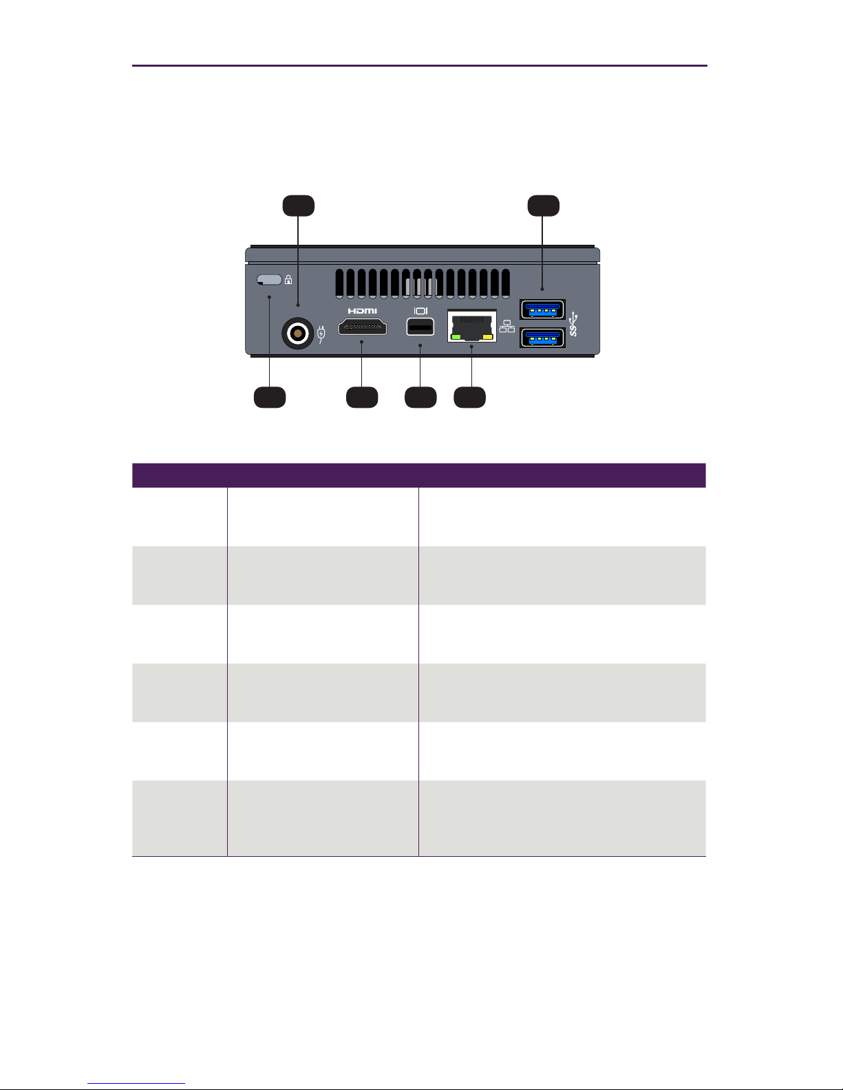
Panel Descriptions
Rear View
ID Name Description
1 Security port This port accepts a standard computer
laptop locking connector.
2 Power receptacle Connect the included power supply to this
power receptacle.
3 HDMI Connect an HDMI cable from this port
on the Management Platform to an HD
display. (optional)
4 Mini DisplayPort Connect a Mini DisplayPort cable from this
port to a DisplayPort interface (optional).
5 Ethernet port Connect an Ethernet cable from this port to
a switch on the Local Area Network.
6 USB port Connect up to two USB 2.0 devices, such
as a keyboard and mouse, to these USB
ports.
Getting Started
2
6
3 4 5
2
1
Page 10
3
Getting Started
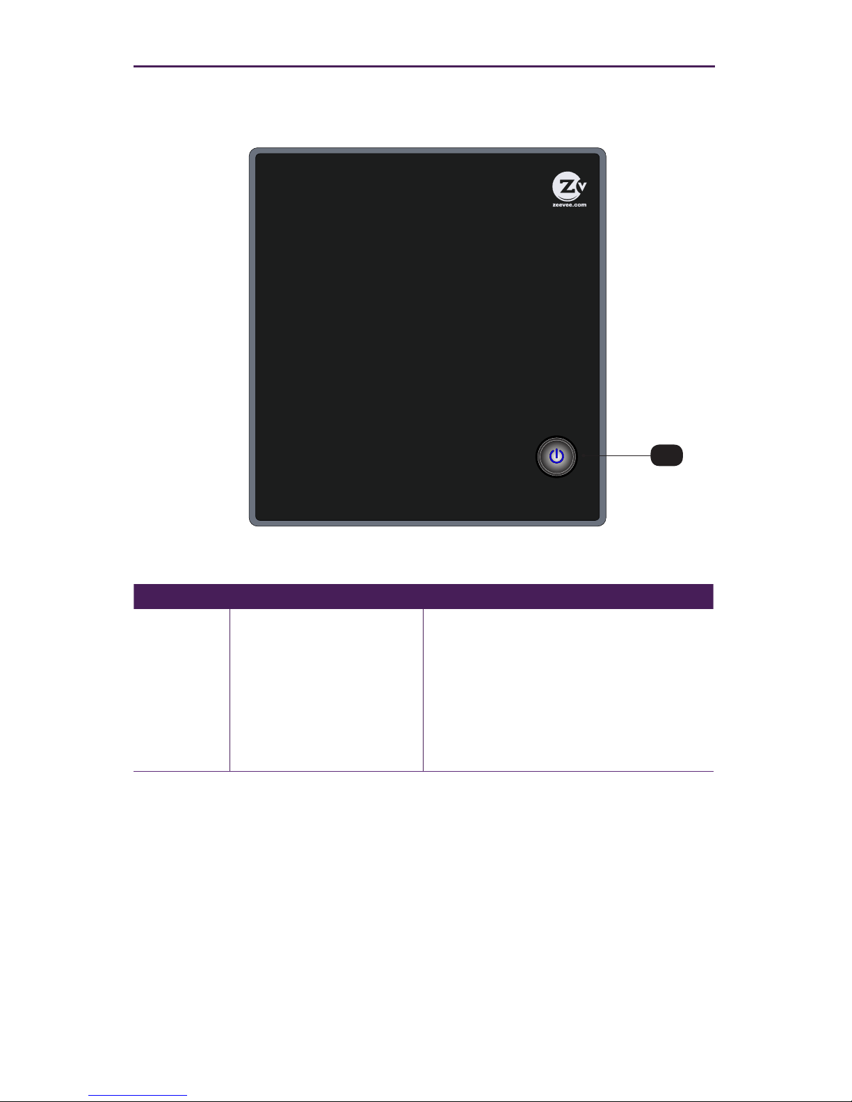
Top View
ID Name Description
7 Power On/Off Press this button to manually power-off
the Management Platform. When the
Management Platform is connected to a
power source, it will automatically poweron. In addition, if power is lost or the
power is disconnected, the Management
Platform will automatically power-on when
power is restored.
ZyPerMP
ZyPer Management Platform
Intelligent IP Distribution
Power On/Off
7
Page 11
4
Getting Started
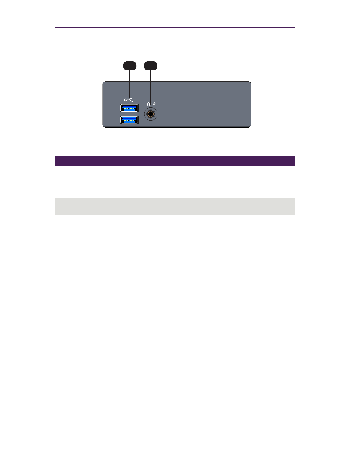
Front View
ID Name Description
8 USB port Connect up to two USB 3.0 devices, such
as a keyboard and mouse, to these USB
ports.
9 Headphone / Mic jack Not used.
ZyPerMP
ZyPer Management Platform
Intelligent IP Distribution
Power On/Off
8 9
Page 12

Getting Started
5
Installation
1. Connect the included power supply to the power receptacle on the ZyPer Management Platform.
2. Connect the included AC power cord from the power supply to an available electrical
outlet.
3. Connect an Ethernet cable from the ZyPer Management Platform to a switch that
is on the same LAN that will be hosting the ZyPer devices. Although the ZyPer
Management Platform can be connected anywhere on the LAN, it is recommended
that it is connected to the primary switch where the ZyPer endpoints are connected.
NOTE: If the ZyPer Management Platform does not detect a DHCP server within 60
seconds, a link-local address of 169.254.xxx.xxx will be assigned to the ZyPer
Management Platform. If you wish to use static or xed-mapping using DHCP, then
see Network Conguration (page 8).
Using Windows®
a. Connect an Ethernet cable from your computer to the same switch as above.
b. Go to the Network folder.
c. Locate the icon titled “ZyPer Management Server” followed by an IP address.
This is the IP address of the ZyPer Management Platform.
Using OS X®
a. Connect an Ethernet cable from your computer to the same switch as above.
b. Open the Terminal application.
c. At the prompt, enter ping zyper.local.
d. The IP address of the ZyPer Management Platform will be displayed.
Page 13
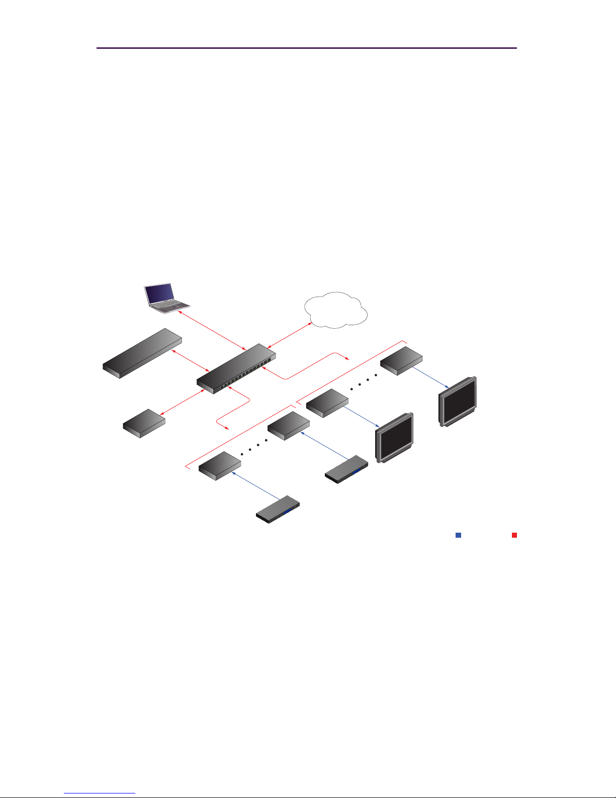
6
Getting Started
HDMI Ethernet
Display/Projector
LAN
Display/Projector
Automation
Control System
Computers
Zyper
Management
Platform
Managed
Switch
HD Source
HD Source
Decoders
Encoders
4. Open a web browser and enter the IP address of the ZyPer Management Platform.
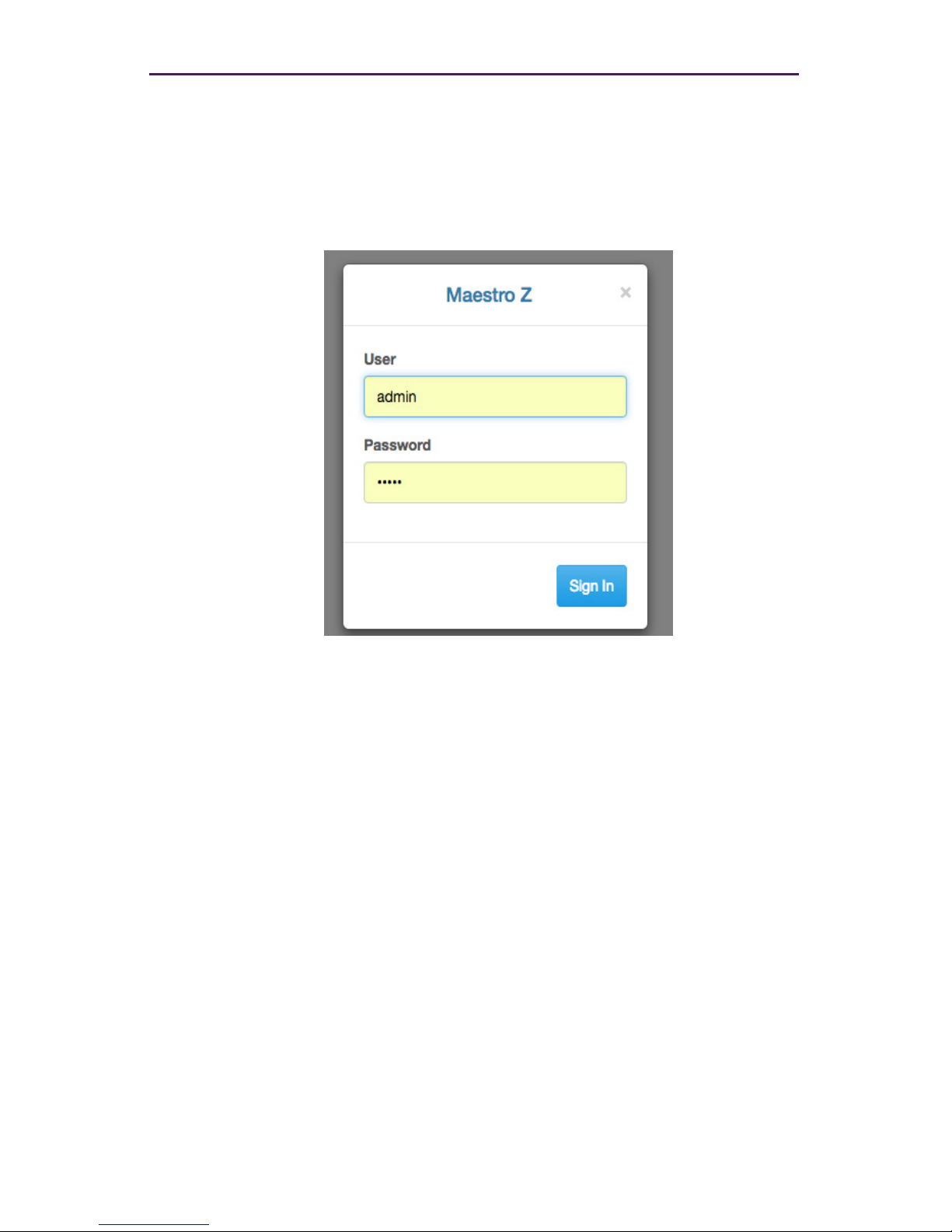
5. The login screen for the Maestro Z will be displayed.
6. Enter admin for both the Username and Password elds.
See Management Platform Login (page 7) for more information.
7. Click the Login button.
Sample Application Diagram
Page 14

7
Management Platform Login
1. At the login prompt, enter the following login name: zyper
After entering the login name, the password prompt will be displayed.
zyper login: zyper
Password:
2. Enter the password. The default password is zyper. Note that the password will
not be echoed to the screen. Once the password is entered, the screen will appear
similar to the following:
zyper login: zyper
Password:
Last login: Mon Mar 28 16:36:11 EDT 2016 on tty1
Welcome to Ubuntu 14.04.2 LTS (GNU/Linux 3.16.0-49-generic
x86_64)
* Documentation: https://help.ubuntu.com/
494 packages can be updated.
268 updates are security updates.
zyper@zyper:~$
3. At the prompt, type ifcong to display Management Platform network conguration.
The current IP address will be located on the second line of information, as shown:
zyper@zyper:~$ ifcong
eth0 Link encap: Ethernet HWaddr 40:8d:5c:32:45:d5
inet addr: 192.168.1.6 Bcast:192.168.1.255
Mask:255.255.255.0
...
...
Getting Started
Page 15

8
Network Conguration
The default conguration of the Management Platform will use DHCP with link-local
addressing support. Link-local addressing allows the Management Platform to have an IP
address on a network, even if the Management Platform has not been manually congured
or automatically congured by a DHCP server. If a DHCP server is not detected within 60
seconds, a link-local address of 169.254.xxx.xxx will be assigned to the Management
Platform.
If you wish to use a static IP address, this can be done in one of two ways: Add a xed
mapping to the DHCP server or by directly assigning a static address to the Management
Platform. Both methods are covered in this section.
Fixed Mapping using DHCP
1. Use the ifcong command, from the Linux prompt to identify the MAC address of the
Management Platform.
zyper@zyper:~$ ifcong
eth0 Link encap: Ethernet HWaddr 40:8d:5c:32:45:d5
inet addr: 192.168.1.6 Bcast:192.168.1.255
Mask:255.255.255.0
...
...
2. Use the HWaddr value when conguring the DHCP server to assign a xed IP.
Using Telnet, the show server info command can also be used to obtain the MAC
address of the Management Platform. Refer to API Command Listing (page 61) for
a full listing of available commands.
3. Reboot the Management Platform, using the following command, to use the new IP
address.
zyper@zyper:~$ sudo reboot
Getting Started
Before continuing, make sure that the static IP address being used does
not conict with any DHCP-assigned addresses. Contact your system
administrator for assistance.
Page 16

9
Getting Started
Static IP Conguration
1. At the prompt, launch the Emacs editor using the following command.
zyper@zyper:~$ sudo emacs /etc/network/interfaces
2. Enter the password. The default password is zyper. The password will not be
echoed to the screen.
zyper@zyper:~$ sudo emacs /etc/network/interfaces
[sudo] password for zyper:
3. Once the correct password is entered, the screen will display the Emacs editor.
4. Information, similar to the following, will be contained in the interfaces le.
auto eth0
allow-hotplug eth0
iface eth0 inet dhcp
#auto eth0
#iface eth0 inet static
#address 192.168.1.8
#netmask 255.255.255.0
#gateway 192.168.1.1
Lines that have the # symbol are not executed. So, we need to remove them and
place them at the beginning of the rst three lines.
5. Change the le so it appear as follows, making sure that your own IP settings are
used.
#auto eth0
#allow-hotplug eth0
#iface eth0 inet dhcp
auto eth0
iface eth0 inet static
address 10.5.68.100
netmask 255.255.255.0
gateway 10.5.68.1
Before continuing, make sure that the static IP address being used does
not conict with any DHCP-assigned addresses. In addition, the following
steps make use of the Linux Emacs editor which is beyond the scope of
this manual. If you are unfamiliar with this editor, contact your system
administrator for assistance.
Page 17

10
Getting Started
6. Save the le and exit the Emacs editor. (Ctrl+x then Crtl+c) When prompted to save
changes type y
7. Reboot the Management Platform using the following command.
zyper@zyper:~$ sudo reboot
Page 18

2 Basic Operation
Page 19
12
Accessing Maestro Z
1. Open a web browser and enter the IP address of the Management Platform.
2. The login screen for Maestro Z will be displayed.
3. Enter the required information in the Username and Password elds. The default
username and password is admin. The username and password are case-sensitive.
The “admin” password may be changed by the user at any time.
4. Click the Sign In button.
5. The Home page will be displayed. See the next section for more information.
Basic Operation
Page 20
13
Home Page
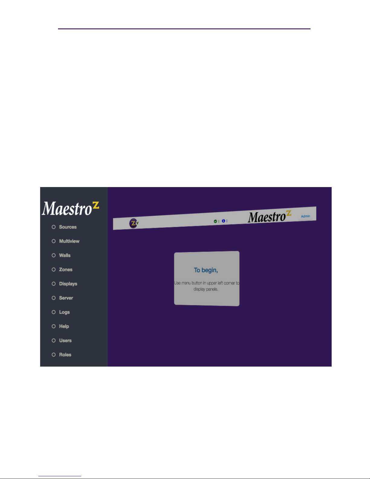
The Home page of the Maestro Z displays all available Sources, Displays, Walls, Zones,
Multiviews, Server Info, Users, Roles, Logs and Help.
1. Login to the Maestro Z. Refer to Accessing Maestro Z (page 12) for more information.
2. The Home page will be displayed. The Sources pane displays all available
encoders . The Displays pane displays available decoders. Walls, Multiview, Zones,
Users and Roles will be covered in upcoming sections.
Basic Operation
Page 21
14
Basic Operation
Device Status Indicators
Each Source and Display contains a status indicator border color, displaying current
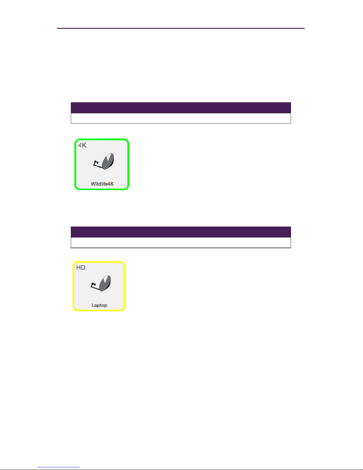
information about the device. This is particularly useful for devices that may be in a
separate part of a building or several miles away.
Meaning Indicator Color
OK Green
1. Indicates that an HDMI cable is connected between
the encoder and the source or between the decoder
and a display or other sink device.
2. The encoder / decoder is powered.
3. The Ethernet cable is connected between the switch
and the encoder / decoder.
Meaning Indicator Color
Warning Yellow
1. HDMI cable may not be connected between the
encoder and the source or between the decoder and a
display or other sink device.
Note that this indicator may also indicate a faulty
HDMI cable.
2. The encoder / decoder is powered.
3. The Ethernet cable is connected between the switch
and the encoder / decoder.
Page 22
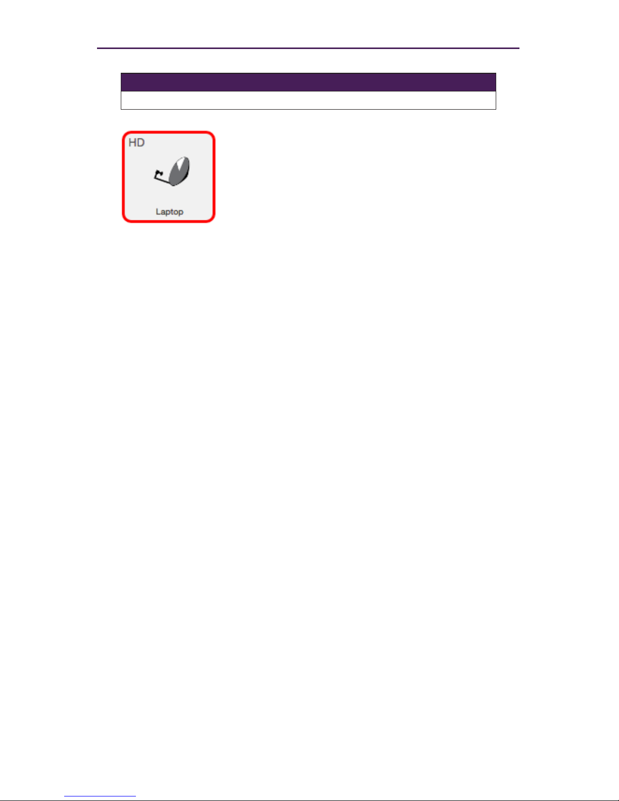
15
Basic Operation
Meaning Indicator Color
Error Red
1. The Ethernet cable is disconnected between the switch
and the encoder / decoder.
2. The encoder / decoder may not be powered.
Page 23
16
Basic Operation
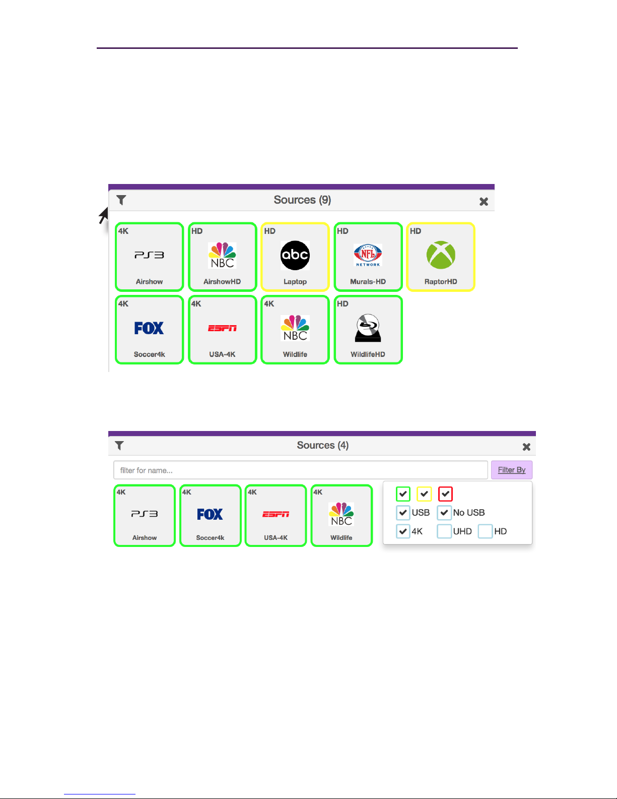
Displaying Devices By Status
Both the Sources and Displays window contain a Filter by status option. There are
check boxes to lter by Status (Green, Yellow, Red), Device Type (4K, UHD or HD), USB
(Present, Not present) There is also an option to lter Sources or Displays by name.
1. Click the Filter Icon.
2. Only those devices with the selected status will be displayed. As illustrated in this
example, only ZyPer4K devices are shown in the Sources window. ZyPerHD and
ZyPerUHD sources are ltered out.
3. Select every box from the Filter to show all devices.
Page 24
17
Basic Operation
Displaying Devices By Name
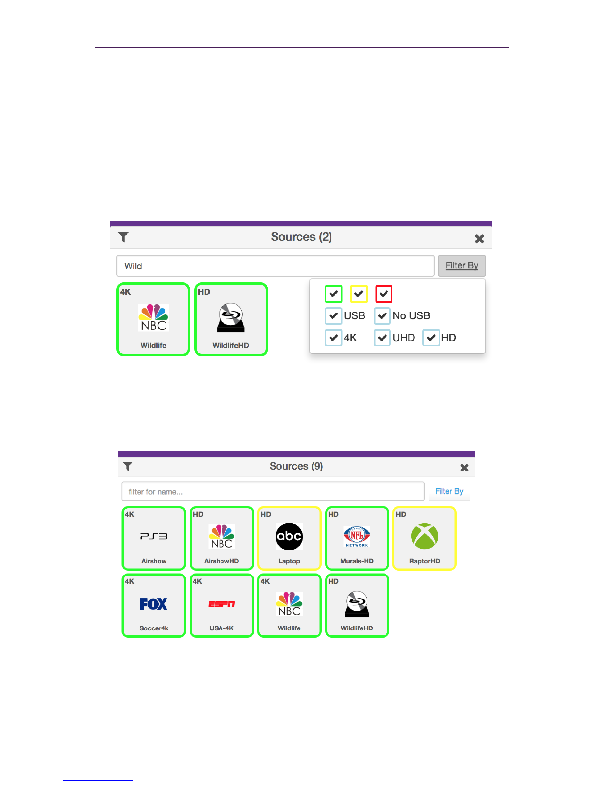
Both the Sources and Displays windows contain a Filter by name eld. Use this eld to
enter the name of the desired device(s) to be displayed.
As text is entered, the interface automatically begins a search of the current string for each
recognized device. Devices that are displayed must contain the text (in sequence) that is
currently in the Filter by name eld. Text searches are case-sensitive.
1. Click in the Filter by name eld.
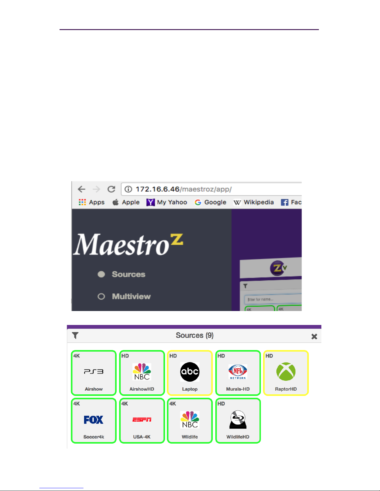
This example uses the following named sources. For more information on naming
sources see Conguring Encoders and Decoders (page 20).
2. Type the desired sequence of characters in the Filter by name eld to search. In this
example, we want to only display the “Wildlife” source devices. To do this, we can enter part of the name, such as “Wild” or even “W” (since no other device name contains
the character “W”). All text entries are case-sensitive.
Page 25
18
Joining Encoders to Decoders
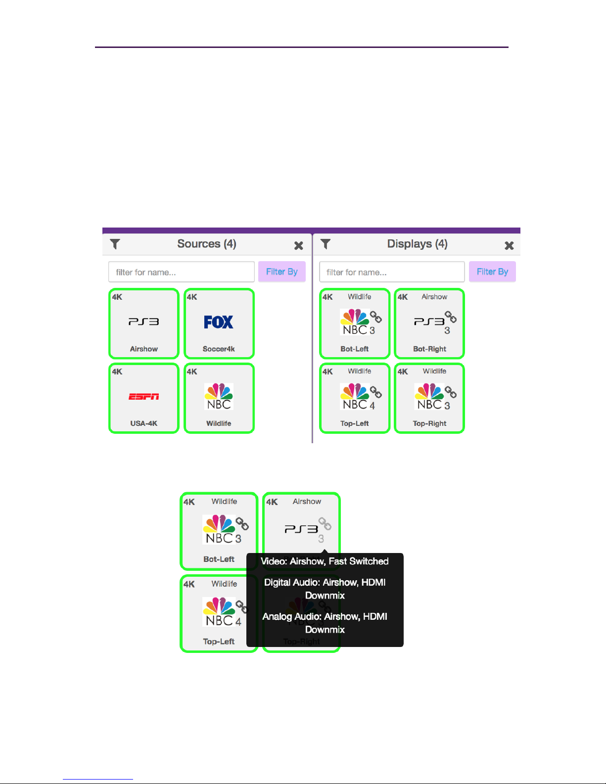
“Joining” is the process of assigning an encoder (source) to a decoder (display) or a video
wall. Before starting the join process, we recommend that you congure the encoder and
decoder settings. Refer to Conguring Encoders and Decoders (page 20).
1. Login to the Maestro Z. Refer to Accessing Maestro Z (page 12) for more information.
2. Drag and drop the desired source on to the desired display.
3. The display icon will change to show that it has now been joined with a source. (Small
chain link icon) Hover over the chain link for additional status info. Also the icon will
change to match the source and name of thesource will appear at the top of the icon.
4. Continue the join process as desired. Note that joining an encoder with a decoder
that is already joined, will replace the previous join operation.
The join command can also be used to perform the same operation.
See API Command Listing (page 61) for more information.
Basic Operation
Page 26
19
Basic Operation
Unlinking Encoders and Decoders
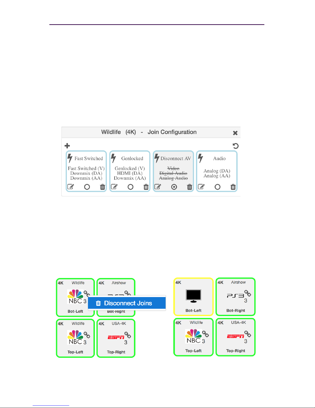
As mentioned earlier, joining an encoder with a decoder that is already joined, will
replace the previous join operation. However, there may be situations where you want
to completely remove any source from being shown on a display. To do this, use the
Disconnect AV feature or Disconnect Joins.
1. Login to the Maestro Z. Refer to Accessing Maestro Z (page 12) for more information.
2. On the Sources window, right-click on any Source. Select Congure Join and then
Disconnect AV.
3. Drag that source onto the Display that you would like to unlink
4. Alternately you can right click on the “Chain Link” icon and select “Disconnect Joins”
5. The display icon will change to show that it has been unlinked and no longer joined
with any encoder. (Yellow perimeter, small chain link icon is gone, icon returns to
default and name of joined source is gone)
Page 27
20
Basic Operation
Source Cong Page
Conguring Encoders and Decoders
When an encoder or decoder is connected to the network, the Management Platform
identies each unit by its MAC address. This is the default setting. However, when dealing
with several units, it is much easier to identify a unit by a string name. It is also possible to
assign a preset image to each icon, set the network mode, RS232 settings, and more.
1. Login to the Maestro Z. Refer to Accessing Maestro Z (page 12) for more information.
2. Click the Source or Displays tab at the left of the page. Joining Encoders to Decod-
ers (page 18)
3. All available encoders will be displayed under the Sources window.
Page 28
21
Basic Operation
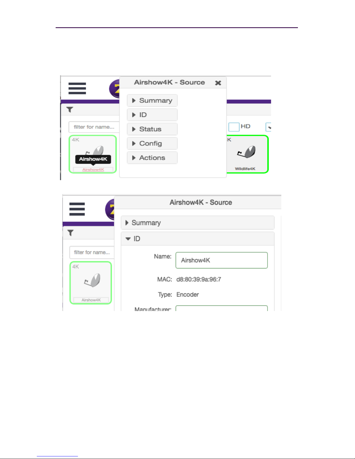
4. Left-click the desired encoder name to display the context menu. In the example
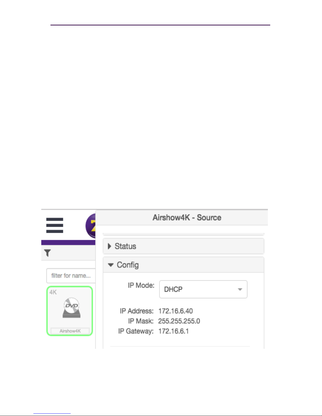
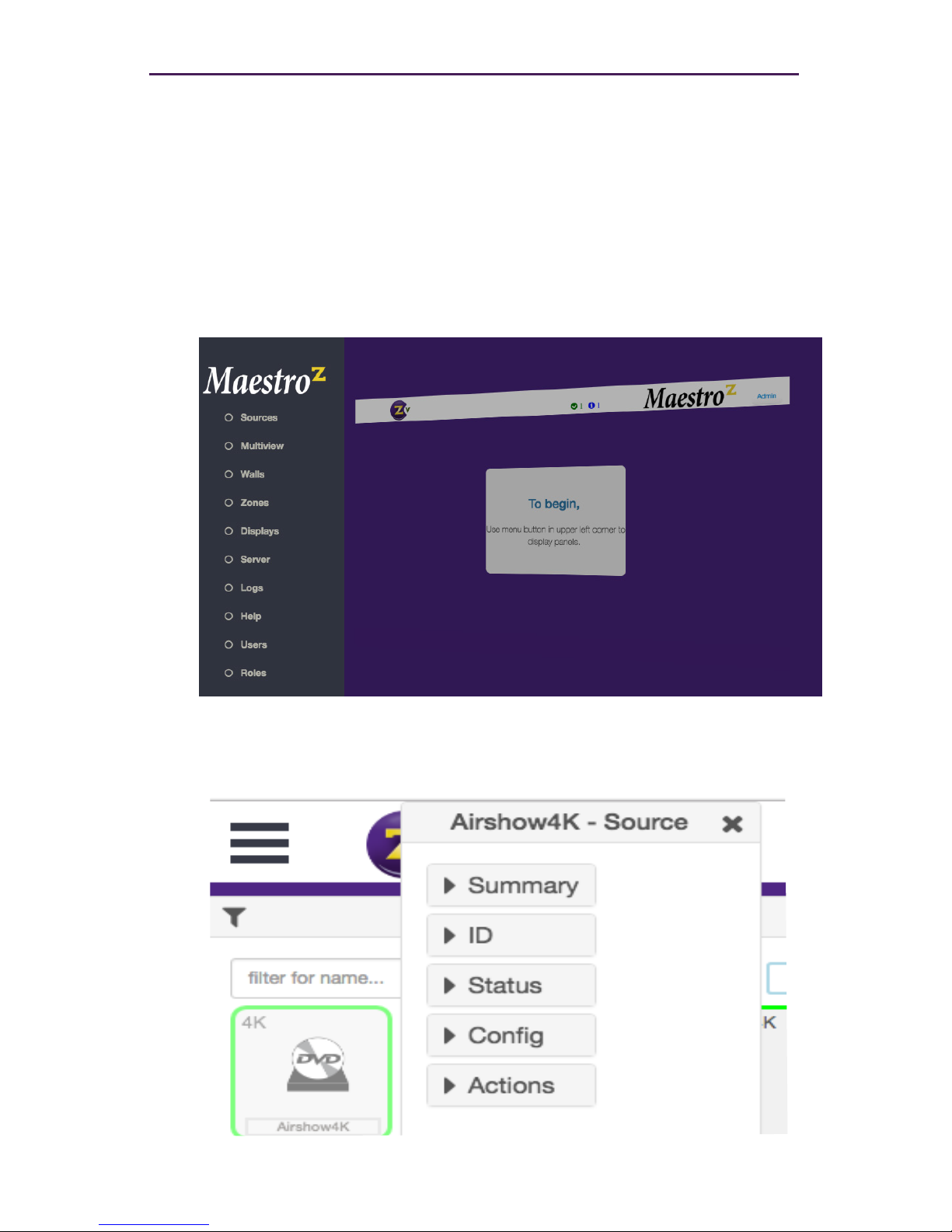
below,we will select the encoder named “Airshow4K”.
5. A menu will appear with options for Summary, ID, Status,Cong and Actions.
6. Selecting the ID option will allow you to manually give the Source a name.
7. Enter a description for the source in the Name eld. By default, the Management
Platform will use the MAC address of the encoder. This eld cannot be blank.
Names cannot contain spaces. In this example, we will use “Airshow4K”.
Naming a device can also be done using the set device general name
command. See API Command Listing (page 61) for more information.
Page 29
22
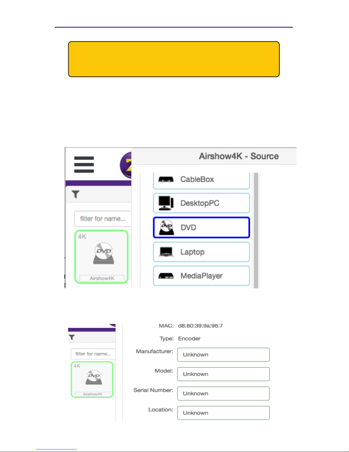
8. Click the Cong-Icon drop-down list to select the desired icon for this source. This is
optional. If no icon is selected, then the default icon will be used. In this
example, we will select DVD, since a DVD player is connected to this encoder.
The set device source-display iconImageName command can also be
used to assign an icon to a device. See API Command Listing (page 61) for more
information.
9. Enter the Manufacturer, Model, and Serial Number of the source or display in the
appropriate elds. By default, these elds are set to “Unknown”. These elds must
not be blank. If a custom value is provided, it must not contain spaces.
Basic Operation
Each encoder and decoder must have a unique name. Duplicate names are
prohibited. It should be noted that assigning a name to an encoder does not
actually replace the MAC address. The Name eld provides a descriptive
identier, rather than a MAC address.
Page 30
23
The Manufacturer, Model, and Serial Number can also be assigned using
the following commands, respectively. See API Command Listing (page 61)
for more information.
► set device source-display manufacturer
► set device source-display model
► set device source-display serialNumber
10. Enter the location of the source or display device in the Location eld. By default, this
eld is set to “Unknown”. This eld must not be blank. If a custom value is provided, it
must not contain spaces.
11. The set device source-display location command can also be used to set
these values. See API Command Listing (page 61) for more information for
more information.
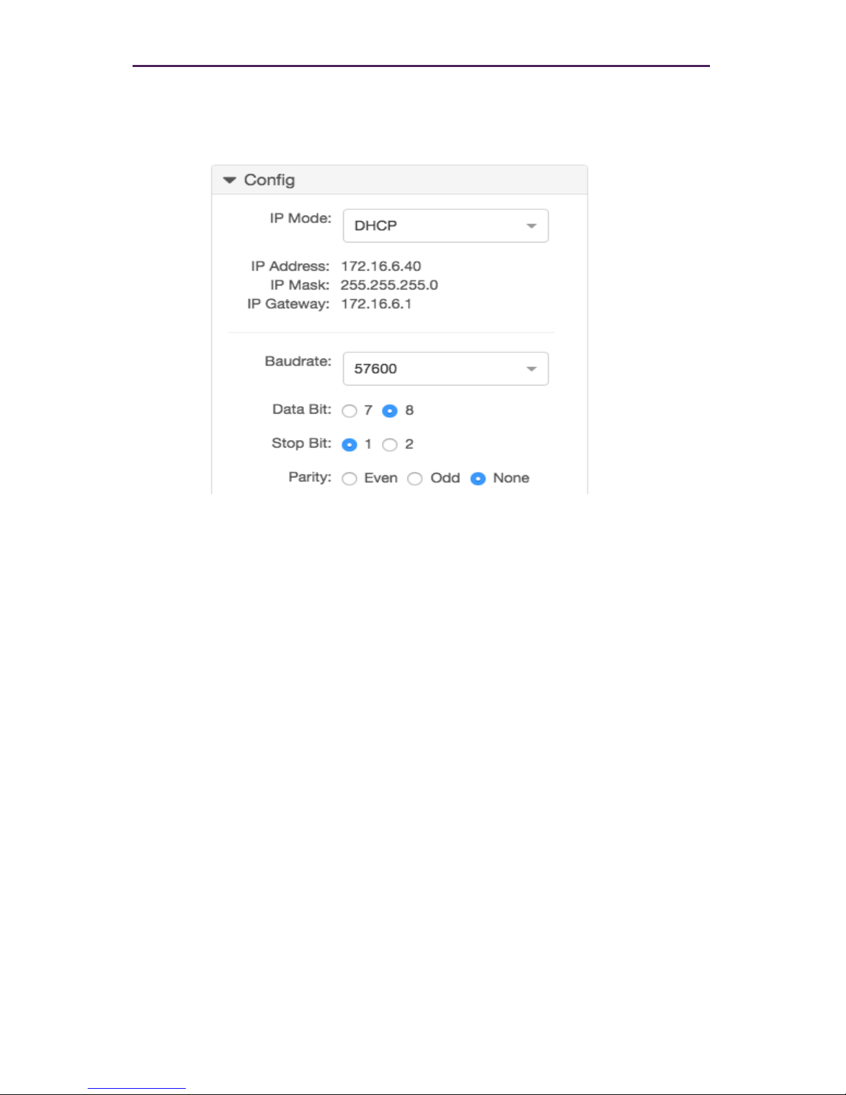
12. Use the Cong-IP Mode section to congure the IP setting for the encoder. By de-
fault, both encoders and decoders are set to DHCP mode and will be discovered
automatically by the Management Platform. To manually congure the IP settings
of the encoder, click the Mode drop-down list and select static. Once in static
mode, the information in the Address, Mask, and Gateway elds can be edited.
Basic Operation
Page 31
24
13. Use the Baudrate section of Cong to congure the RS232 settings for the control
device, such as an automation control system. Click the Baudrate drop-down list to
select the desired baud rate of the control device.
The Device IP settings can also be assigned using the set device ip dhcp and
set device ip static commands. When assigning RS232 settings from the
command line, use the set device rs232 command. See API Command Listing
(page 61) for more information.
Basic Operation
Page 32
25
Basic Operation
Encoder and Decoder Status Information
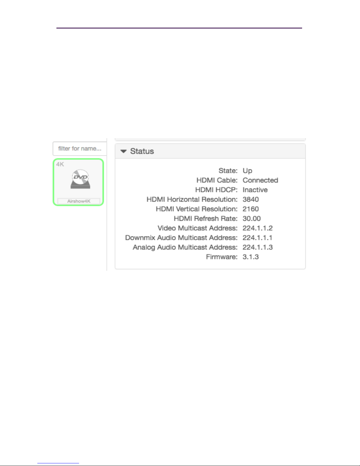
You can obtain status information about an encoder and its source at any time, from the
Source Cong page.
1. Login to the Maestro Z. Refer to Accessing Maestro Z (page 12) for more
information.
2. Left-click the desired source name and select the Status option from the context
menu.
Page 33
26
Basic Operation
Deleting an Encode or Decoder
If an encoder or decoder is disconnected from the network, the Management Platform
will continue to display the encoder within the Maestro Z until it is removed. Note that;
reconnecting the encoder will cause it to once again be displayed in the Maestro Z.
1. Login to the Maestro Z. Refer to Accessing Maestro Z (page 12) for more information.
2. Click the Source tab at the left of the page.
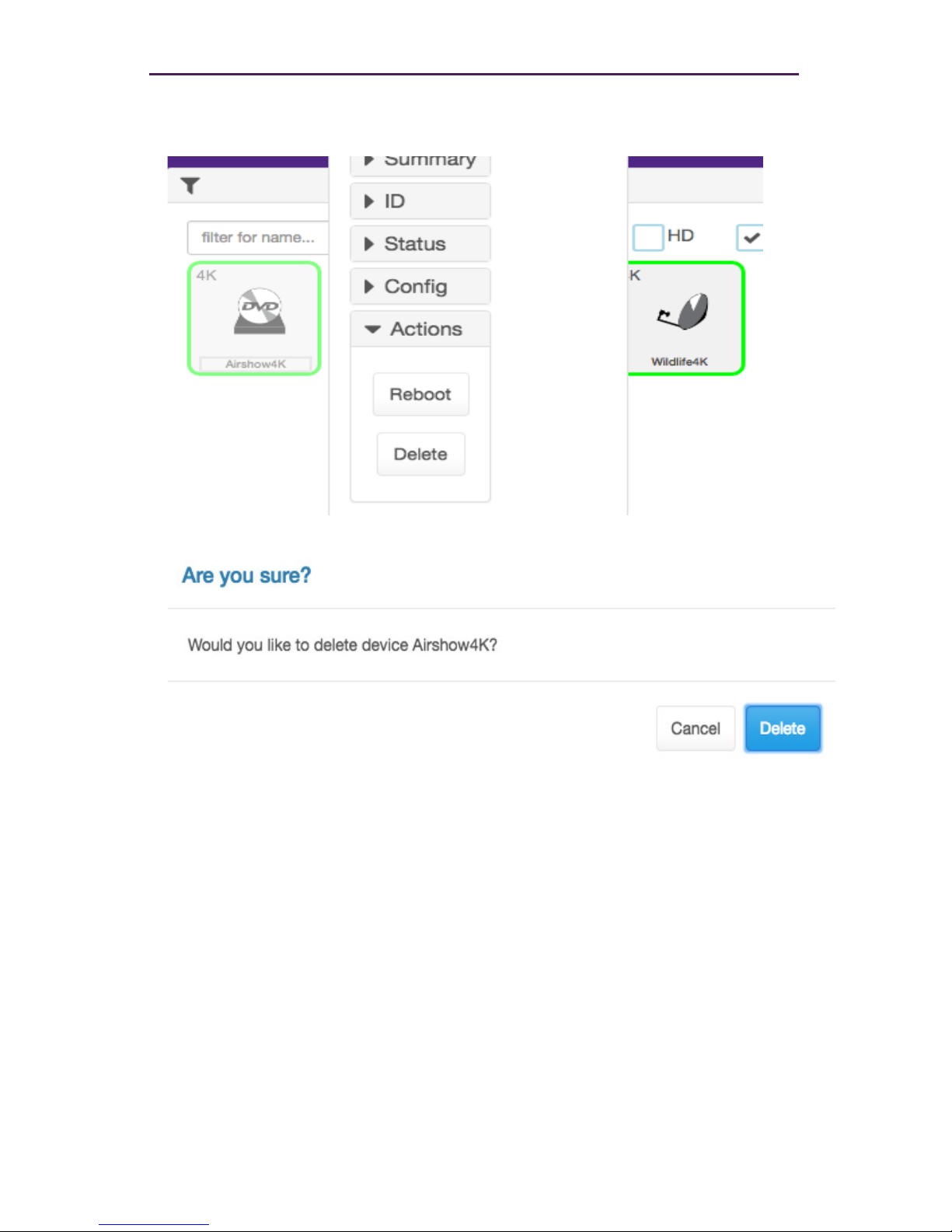
► To delete an encoder:
a. Left-click on the desired encoder and select Actions from the context menu.
Page 34
27
Basic Operation
b. Click the Delete button.
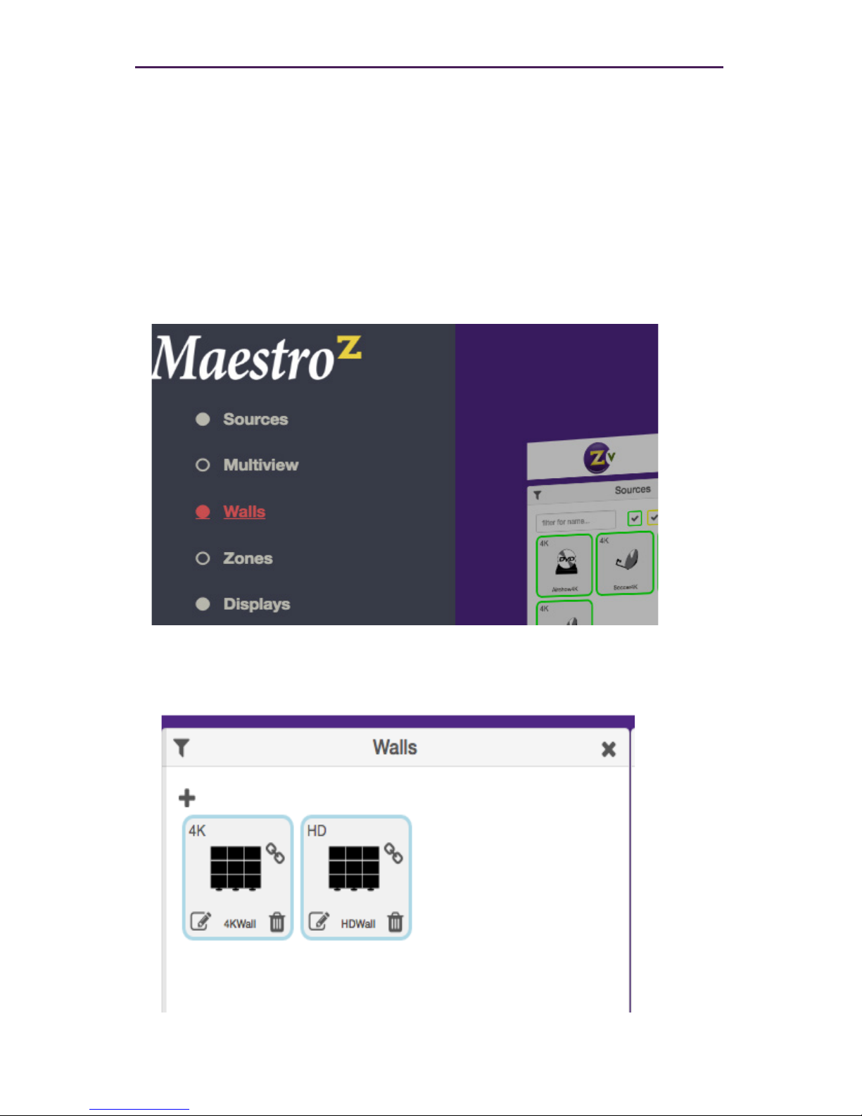
3. The following prompt will be displayed when deleting a source.
4. Click the Delete button to conrm the operation. Click the Cancel button to cancel
the operation.
5. Decoders are deleted in exactly the same manner as Encoders.
Page 35
28
Creating Video Walls
One of the purposes of the Management Platform is to create and manage video walls.
A video wall is a collection of displays or projectors arranged in a square or rectangular
fashion. The source is then “mapped” to each display, thereby creating one large display
from multiple, smaller displays.
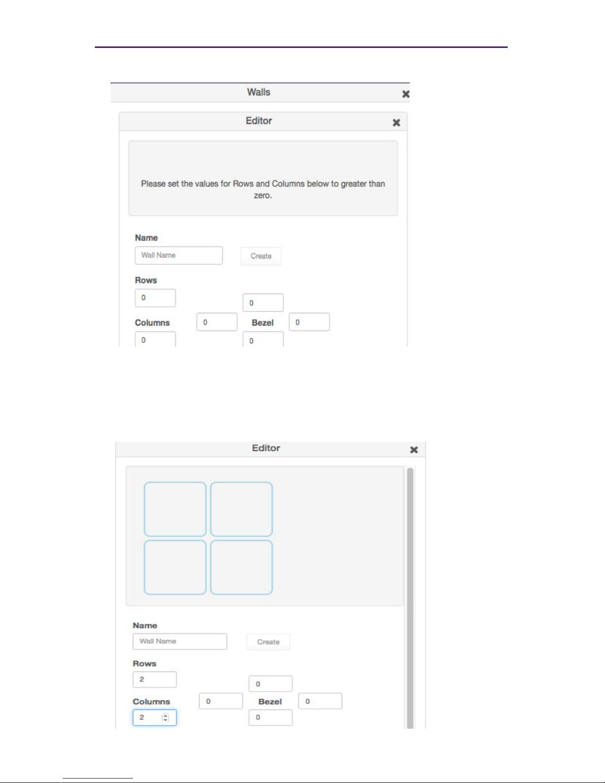
1. Login to the Maestro Z. Refer to Accessing Maestro Z (page 12) for more information.
2. Click the Walls tab at the left of the page.
3. In the Walls pane, click on the + button to create a new video wall.
Basic Operation
Page 36
29
Basic Operation
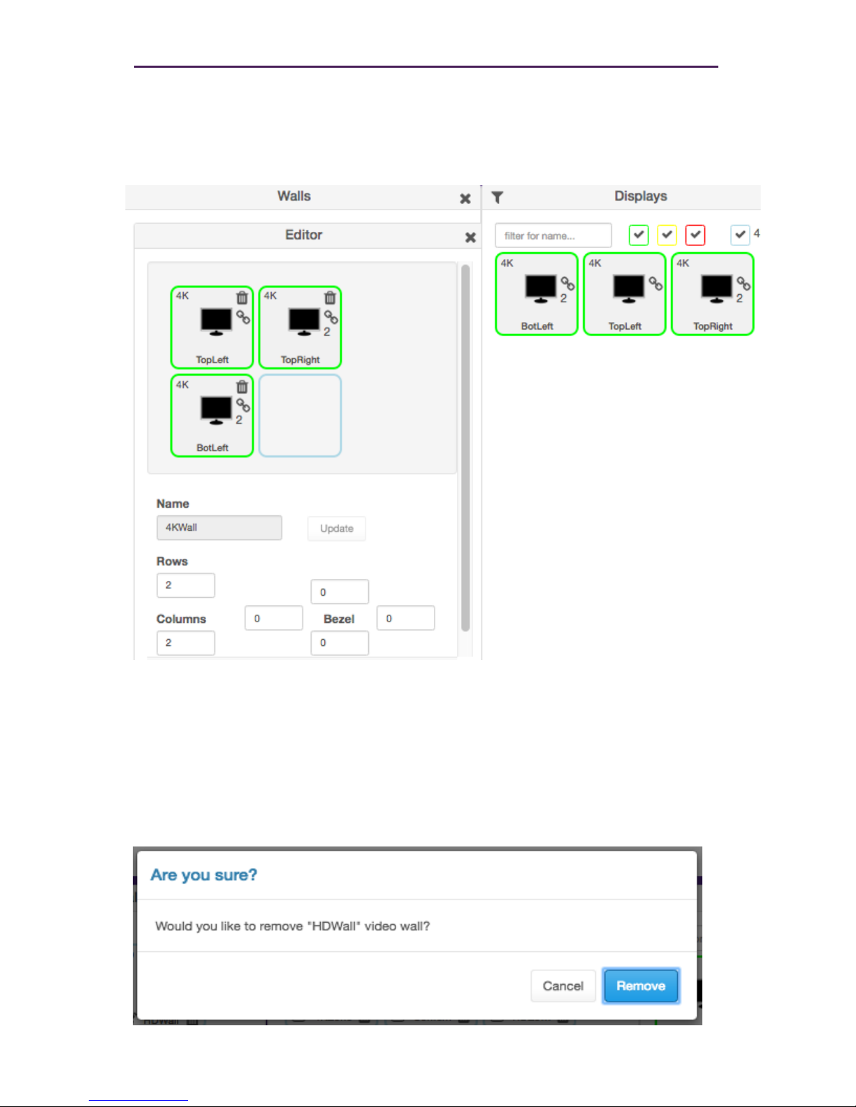
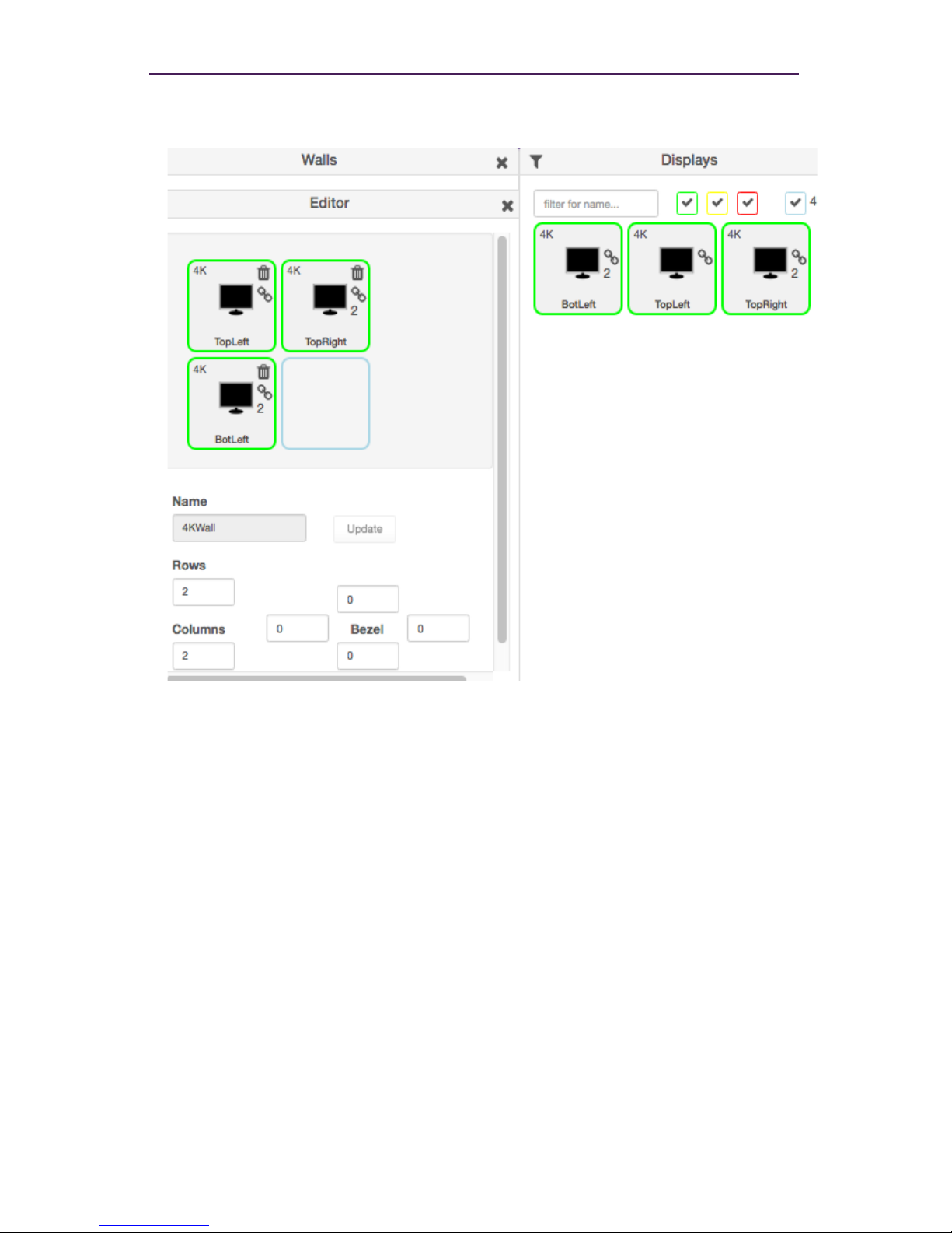
4. This will bring up the wall Editor.
5. Enter the number of display columns in the Number of Columns eld.
6. Enter the number of display rows in the Number of Rows eld.
In this example, we have arranged our displays in two rows and two
columns. This is a blank 2x2 video wall:
Page 37
30
Basic Operation
7. Drag Displays from the Display pane into the Editor to populate the wall. Provide a
name for the new video wall in the Name eld. Values in this eld cannot contain
spaces. Since more than one video wall can be created, always be sure to provide a
descriptive name. This eld cannot be blank.
8. Leave the Bezel Top, Bezel Bottom, Bezel Left, and Bezel Right set to 0.
Bezel compensation will be covered in the next section.
9. Click the Create button.
10. The new Wall will now be available within the Walls window.
11. Video Walls are deleted by clicking on the small Trash Can icon. The user will be
prompted to conrm deletion.
Page 38
31
Basic Operation
Bezel Compensation
Every video output device has an area where video is not displayed. This area is called
the bezel. Bezel compensation takes this area into account when a single video source is
divided and displayed on multiple output devices.
1. Check the output on the video wall and identify any misaligned edges. For best
results, it is recommended to use a static video pattern for this test.
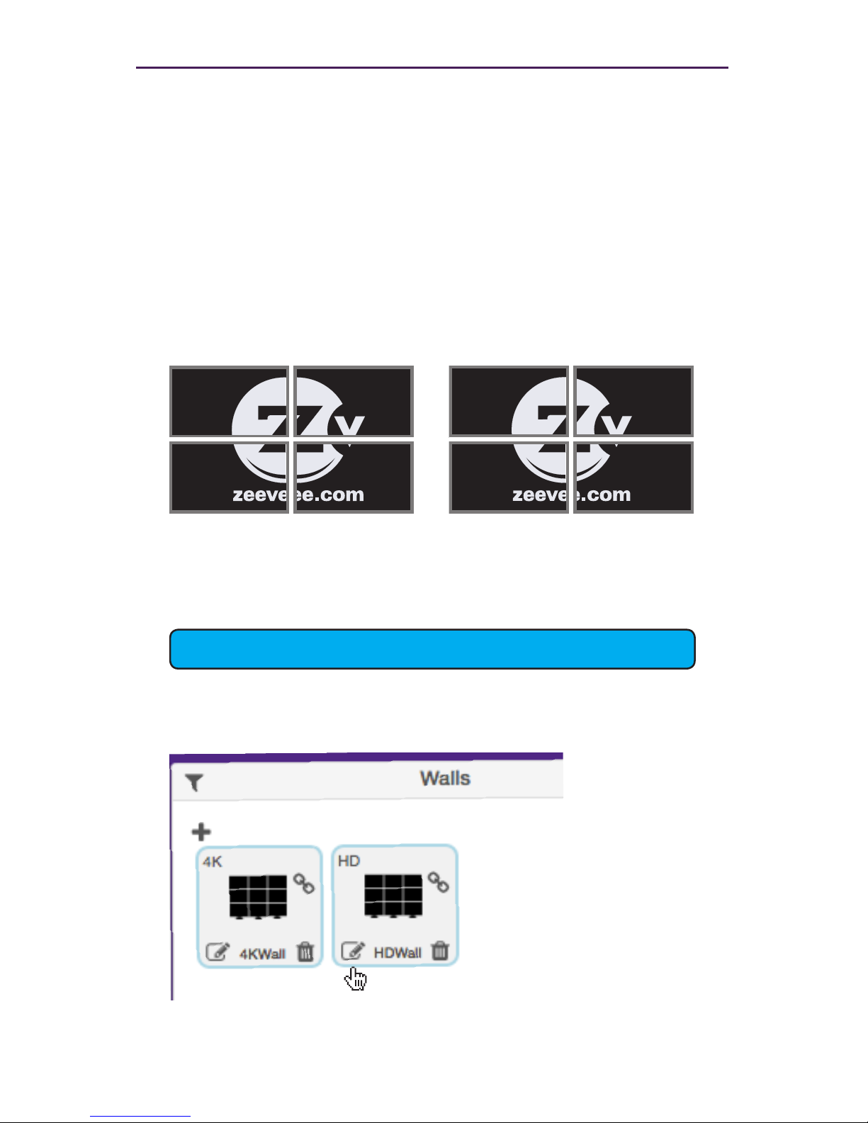
In the illustration on the left, we have a 2x2 video wall without bezel compensation.
Note the ZeeVee logo is not aligned correctly across all four displays. On the right,
bezel compensation is used to x the issue.
It is recommended that when the video wall is set up for the rst time, that these
values be set to zero. Bezel compensation can be changed at any time.
2. Left click the edit video wall button in the lower left corner of the desired wall.
Without Bezel Compensation With Bezel Compensation
Bezel compensation is always measured in pixels.
Page 39
32
Basic Operation
3. The video wall editor will come back up onto the screen.
4. Enter the desired values, in pixels, for each bezel eld: Bezel Top, Bezel Bottom,
Bezel Left, Bezel Right.
5. Once the desired values have been entered, click the Update button. This will save
the new settings.
6. Check the picture on the displays. Repeat steps 2 - 5 as necessary.
7. Note: Only the ZyPer4K allows bezel adjustment. Video walls with the ZyPerHD or
ZyPerUHD do not allow bezel adjustment.
Page 40
33
Commands
Creating a Multiview Screen
One of the purposes of the Management Platform is to create and manage multiview
screens. A multiview screen is a collection of sources arranged on a single display. There
can be up to 9 sources displayed on a single display in a variety of preset patterns.
Note: Only the ZyPer4K versions with the HDMI 2.0 feature support multiview screens. This
feature is not supported by the ZyPerHD, ZyPerUHD or ZyPer4K units with only HDMI 1.4
support.
1. Login to the Maestro Z. Refer to Accessing Maestro Z (page 12) for more information.
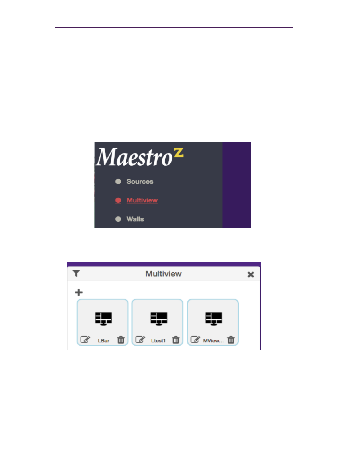
2. Click the Multiview tab at the left of the page.
3. In the Multiview pane, click on the + button to create a new video wall.
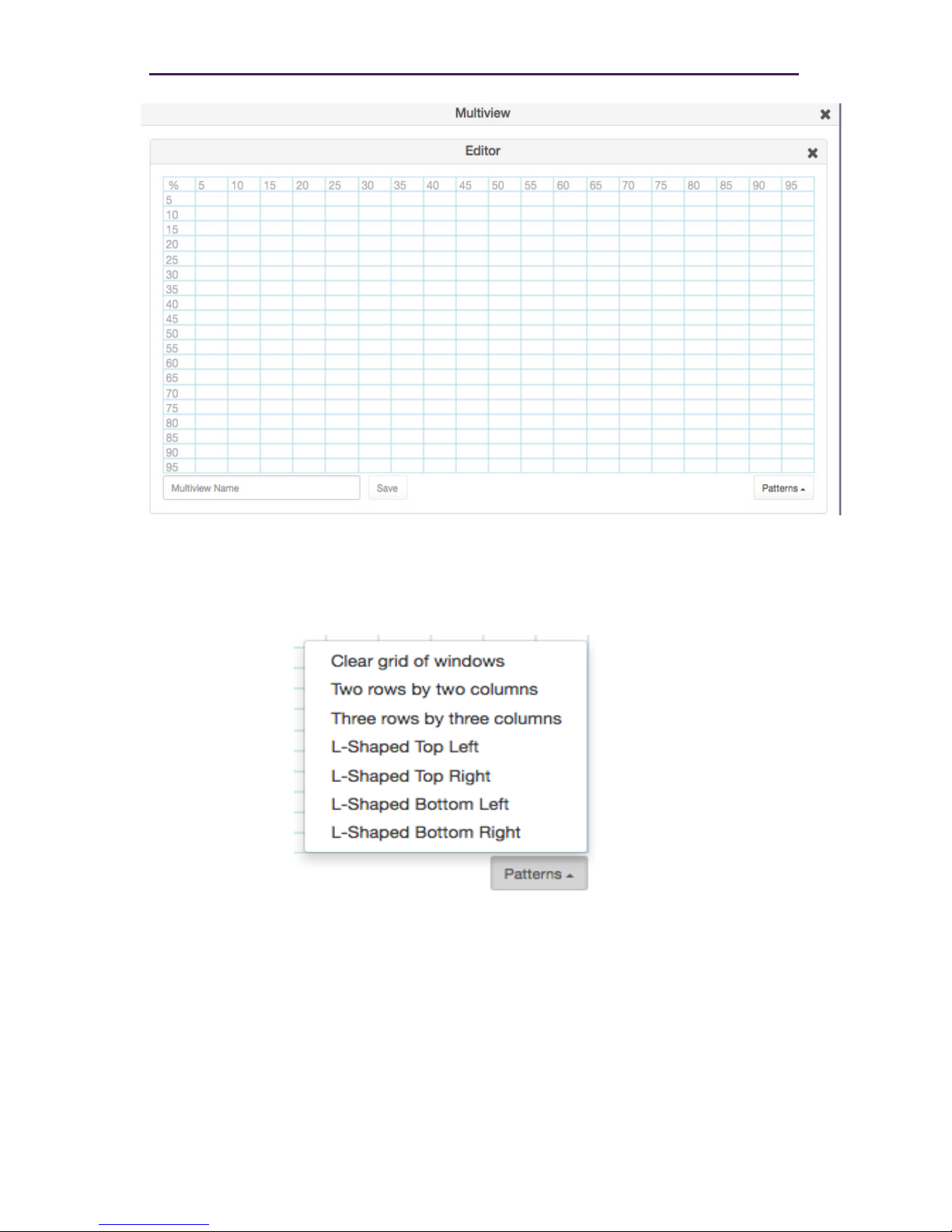
4. This will bring up the Multiview editor where you can create and customize a multiview
display.
Page 41
34
Commands
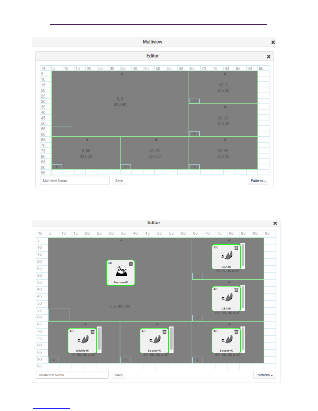
5. Click on the Patterns button in the lower right corner to bring up a list of pre-dened patterns.
6. After selecting a pattern you will see the grid ll in with the places to drag sources.
Page 42
35
Commands
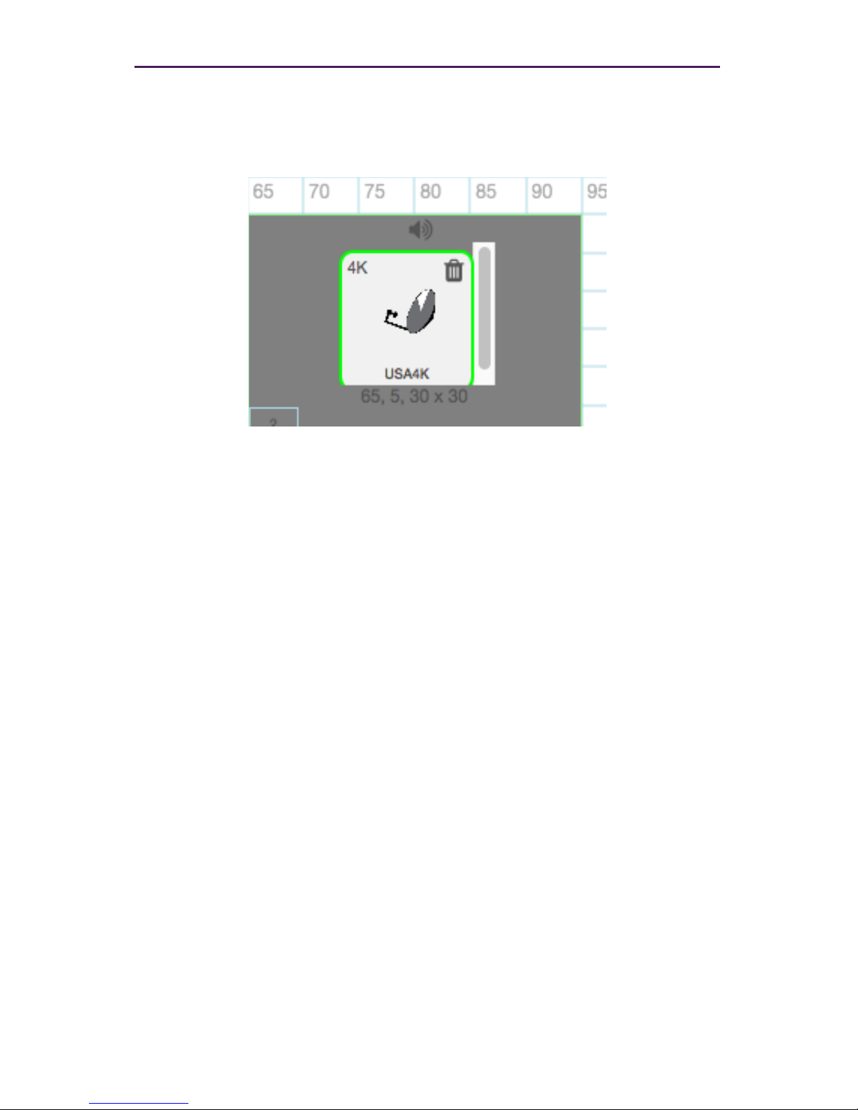
7. Drag sources into the various locations. Note: The same source can be dragged into
muliple windows as long as the windows are the same size. Dragging a source onto
differnent size windows is NOT supported.
Page 43
36
Commands
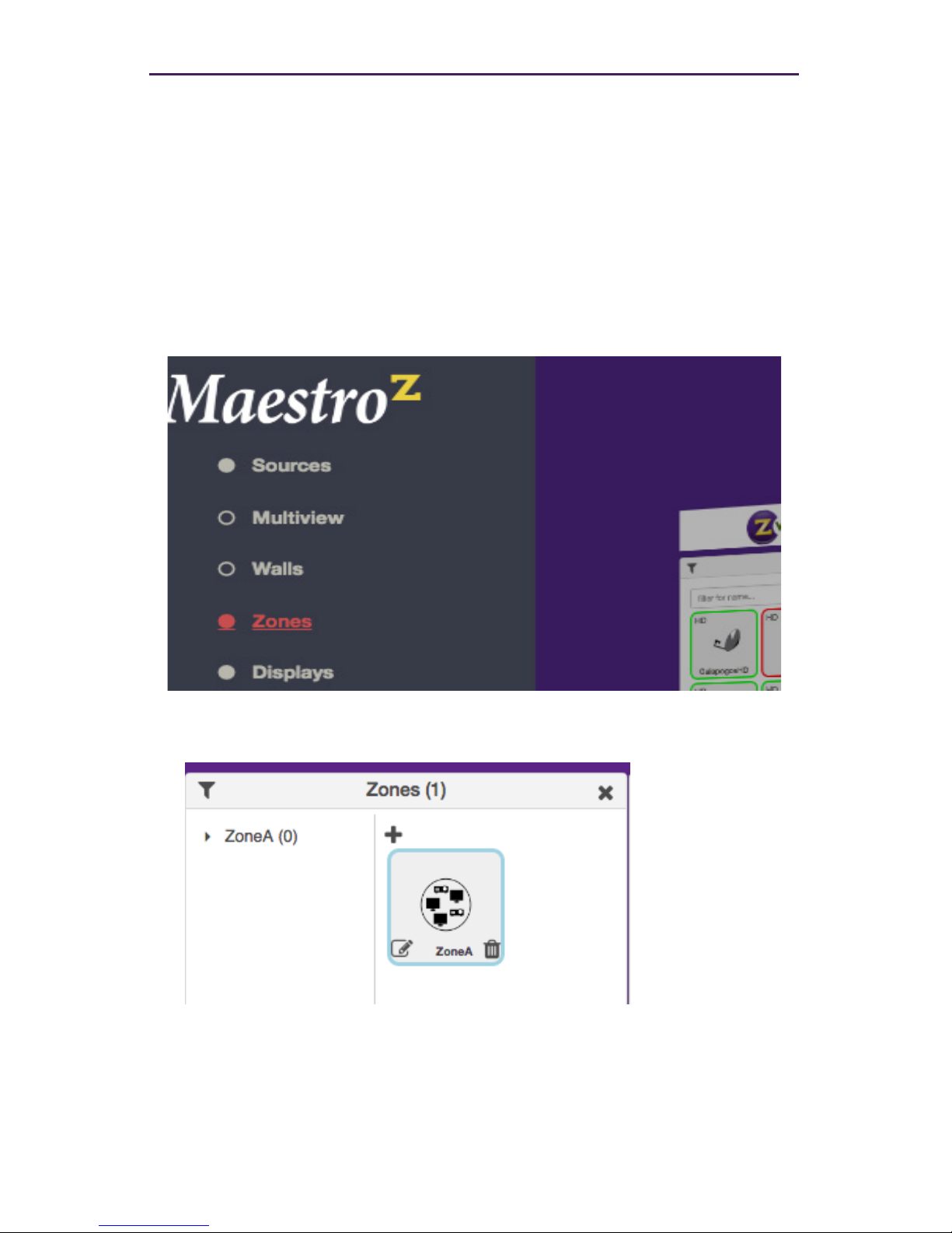
8. If desired, assign Audio from one of the Sources. This is done by clicking on one of the
small Audio symbols in the top center of each Window. Note that only audio from one
source is supported.
9. Give the Multiview a name and press the Save button.
10. To use the Multiview, drag the newly created mulitview onto a Display in the Display
pane. Note that the Display must be a 4K compatible display for this funcitonality to
work.
Page 44
37
Creating Zones
In many installations, displays are placed in more than one room. These rooms are often
referred to as zones. Creating a Zone, using the Management Platform, allows you to
organize these displays in a group. Video Walls can also be added to Zones.
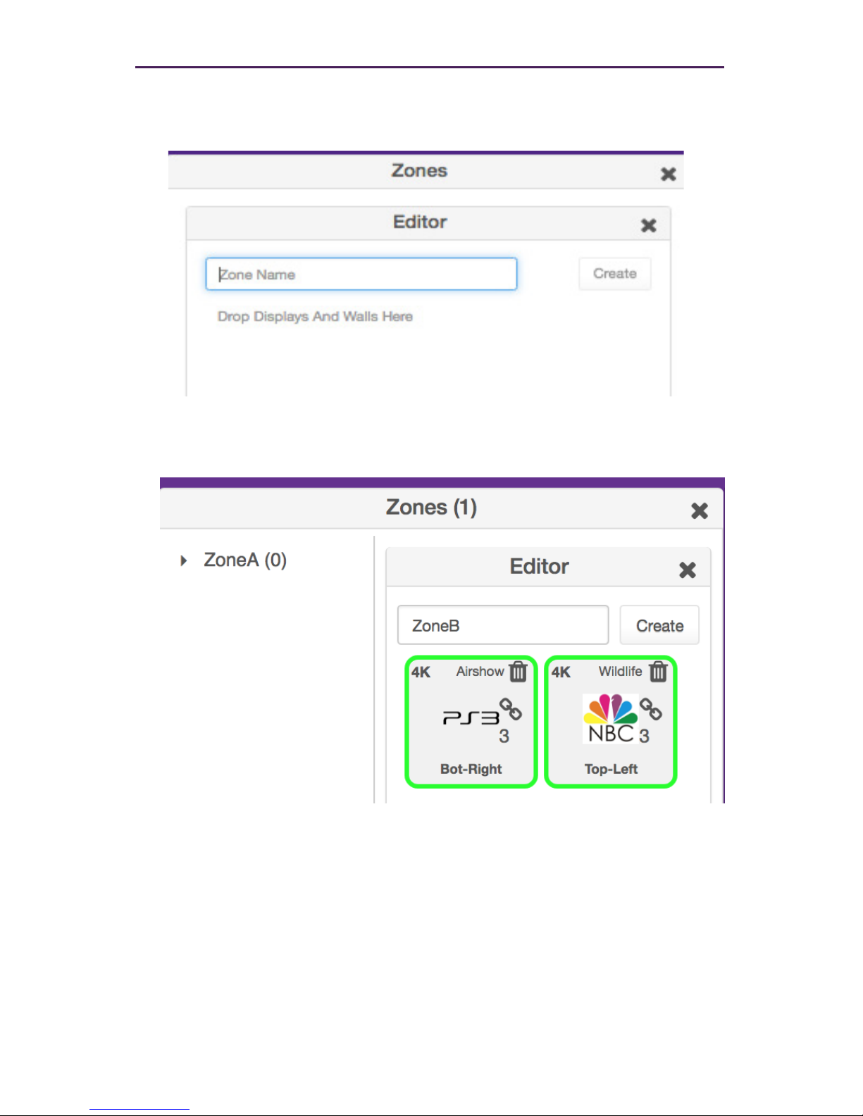
1. Login to the Maestro Z. Refer to Accessing Maestro Z (page 12) for more information.
2. Click the Zones option at the left of the page.
3. In the Zones window, click on the + symbol to add a Zone.
Basic Operation
Page 45
38
Basic Operation
3. This will open the Zones Editor. Drag Display and Video Walls into the Zone from the
Displays or Walls windows.
4. Continue adding the desired displays (or video walls) to the drop-pane.
5. Provide a name for the Zone. If a custom name is used, it must not contain spaces.
In this example, we will call our Zone, “ConferenceRm”, since our displays are
installed in a conference room. It is recommended that a unique and descriptive
name be used to identify each Zone.
Page 46
39
Basic Operation
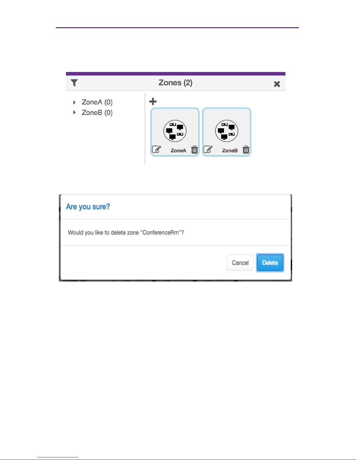
7. Click the Create button to save the Zone. Close the editor window to exit without saving changes.
8. The new Zone will appear under the Zones window.
9. Zones are deleted by clicking on the small Trash Can icon. The user will be prompted
to conrm deletion.
Page 47
40
Basic Operation
Server Functions Page
The majority of this page is used to display general information about the Management
Platform. In addition, this page provides controls for setting the EDID mode and rebooting
or restarting the server. Server rmware can also be updated from this window.
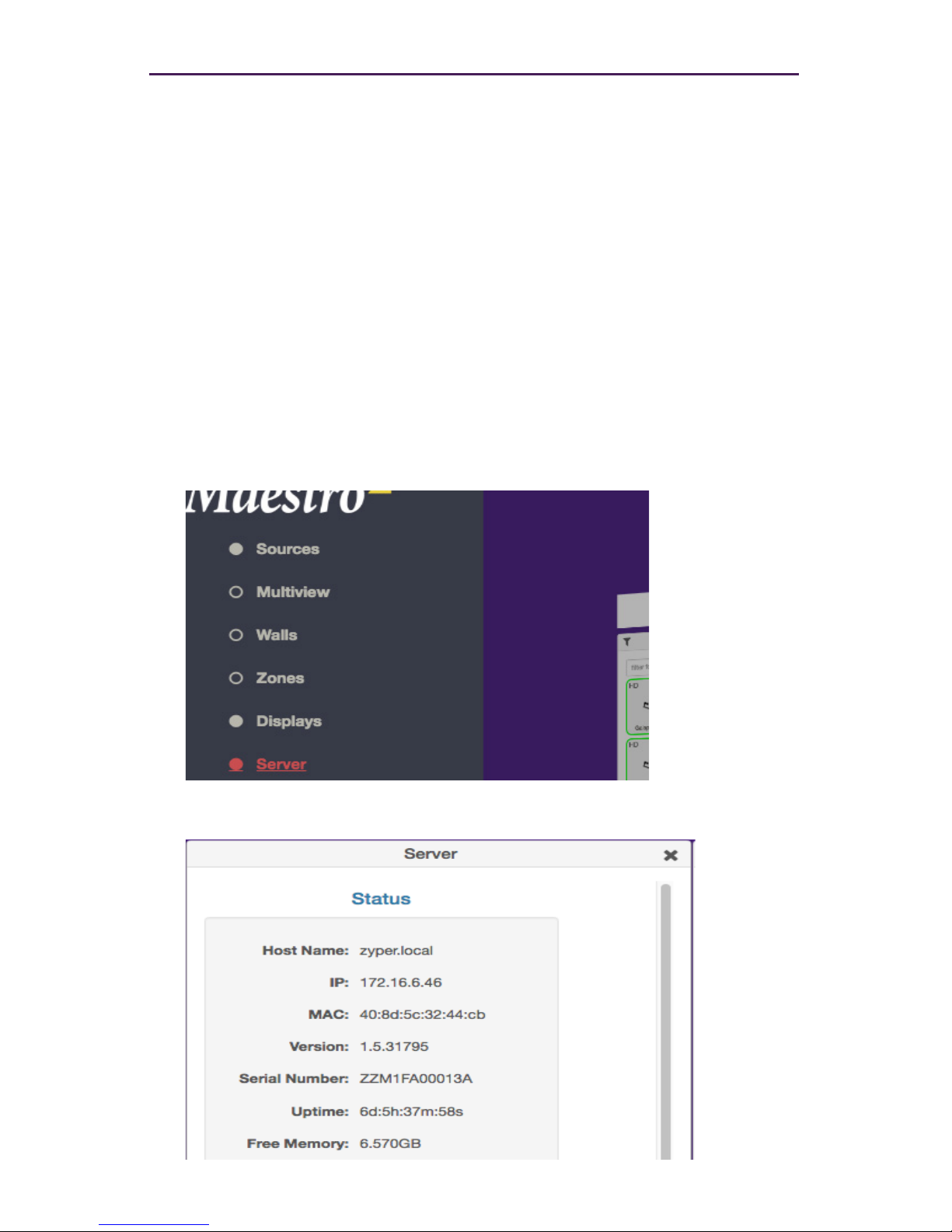
Server Information
This section provides information about the Management Platform, such as the host name,
IP address, MAC address, version, serial number, uptime duration, and free memory.
1. Login to the Maestro Z. Refer to Accessing Maestro Z (page 12) for more information.
2. Click the Server option at the left of the page.
3. Information about the Management Platform will be displayed in the Server pane.
Page 48
41
Basic Operation
Setting the EDID Mode
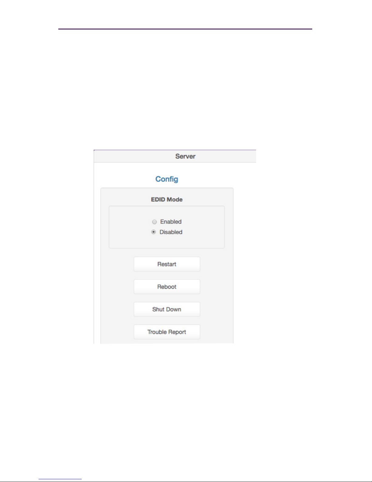
By default, Auto EDID mode is enabled. This means that the Management Platform will
compare the encoder EDID with the decoder EDID. If they are different, then the EDID
from the decoder (sink) will be used by the encoder (source). Setting the EDID Mode
affects all join modes: fast-switched, genlocked, and video-wall. Refer to the join
command in the API Command Listing (page 61) section for more information.
1. Login to the Maestro Z. Refer to Accessing Maestro Z (page 12) for more information.
2. Click the Server tab at the left of the page.
3. EDID information will appear in the Server window under the Status information. You
may need to scroll down in the window to see the EDID information.
Page 49
42
Basic Operation
Server Reboot, Restart, and Shutdown
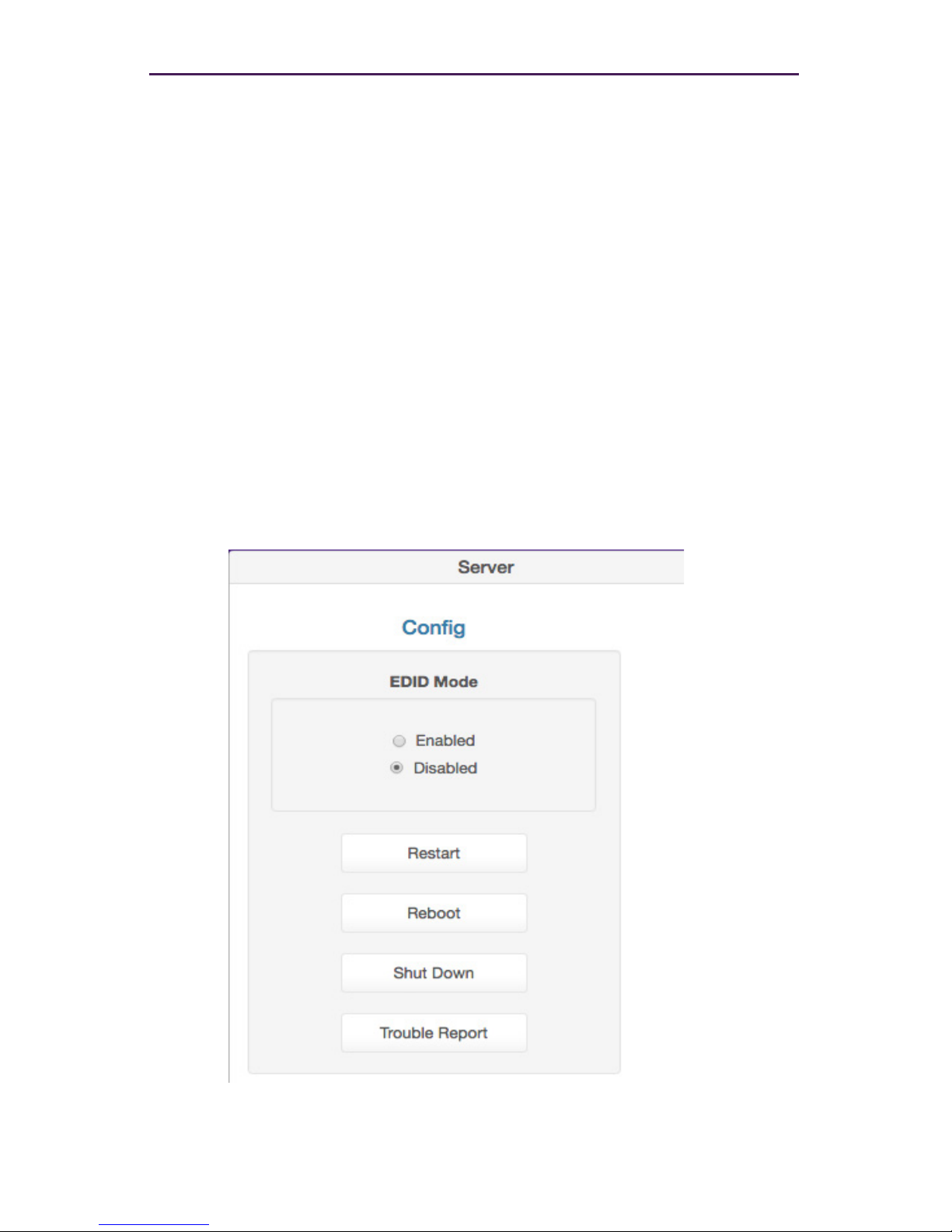
The Management Server can be rebooted, restarted, or shut down from the Server window.
Each option affects the Management Server in different ways, as listed below.
1. Login to the Maestro Z. Refer to Accessing Maestro Z (page 12) for more information.
2. Click the Server tab at the left of the page.
3. Reboot, Restart and Shutdown options will appear in the Server window under the
Status information. You may need to scroll down in the window to see these options.
4. Click the desired button under Server Functions.
► Restart
Restarts the server. Linux is not restarted.
► Reboot
Linux is rebooted.
► Shut Down
Shuts down the Management Server.
► Trouble Report
Generates a trouble report than can be provide to ZeeVee support.
Page 50
43
Commands
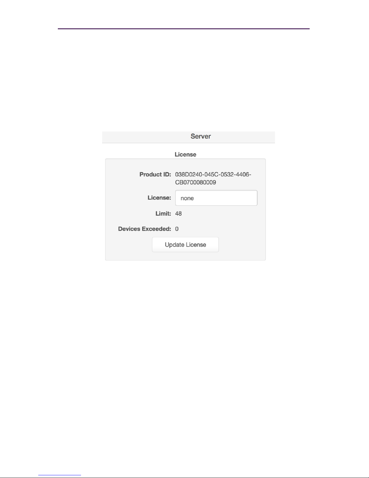
Server License and Update
The License for the Management Server can updated to increase the maximum number of
supported endpoints and ther Server software version can also be updated.
1. Login to the Maestro Z. Refer to Accessing Maestro Z (page 12) for more information.
2. Click the Server tab at the left of the page.
3. Scroll down to the License option..
Here you can enter a new license key as provided by ZeeVee to increase the limit on
the number of endpoints. (Please contact ZeeVee support for additional information)
4. Please see the Appendix of this document for information on updating the Server Software. Note: In a redundant environment, Software must be updated on slave rst,
then switchover, then update on new slave. See online help section 11.2
Page 51
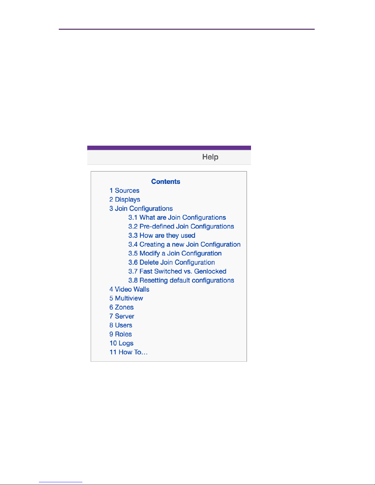
Help Page
The Help page provides a help reference for each page within the Maestro Z.
1. Login to the Maestro Z. Refer to Accessing Maestro Z (page 12) for more information.
2. Click the Help tab at the left of the page.
3. The Management Platform Help window will be displayed.
4. Click the desired section. As the mouse pointer moves over each section, the text will
become underlined.
44
Basic Operation
Page 52
45
Commands
Users and Roles Pages
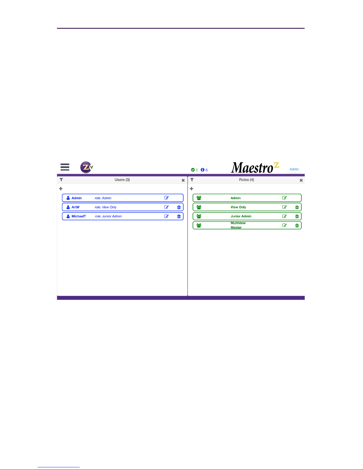
The Users page provides the ability to create additional users beyond the Administrator
and in conjuction with the Roles page assign different access/abilities to each user.
1. Login to the Maestro Z. Refer to Accessing Maestro Z (page 12) for more information.
2. Click the Users tab and Roles tab at the left of the page.
3. The Management Platform Users and Roles windows will be displayed.
The rst User shown in the Users window is Admin. The Admin account cannot be
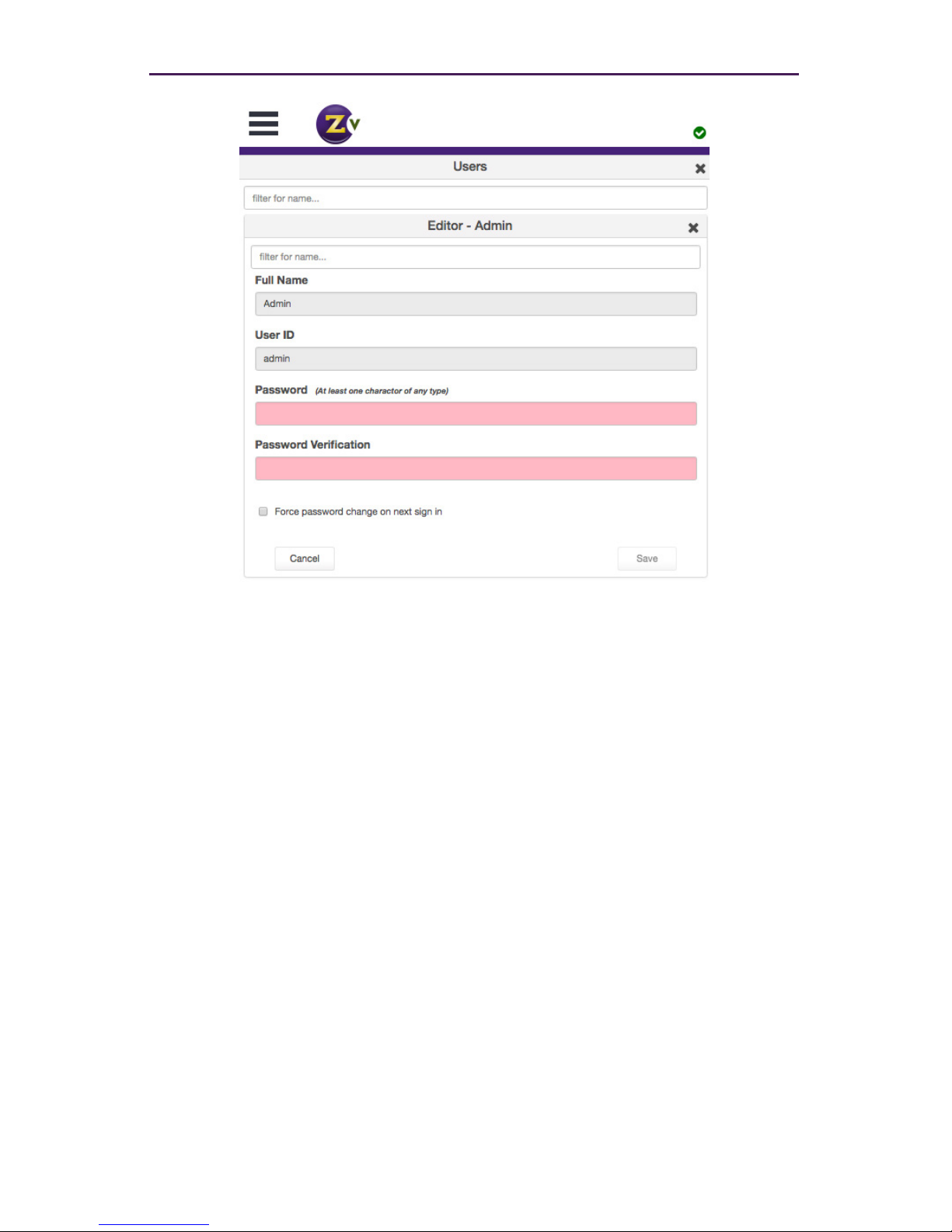
deleted and the name cannot be changed. You can however change the password
from the defalut of “admin” to a password of your choosing.
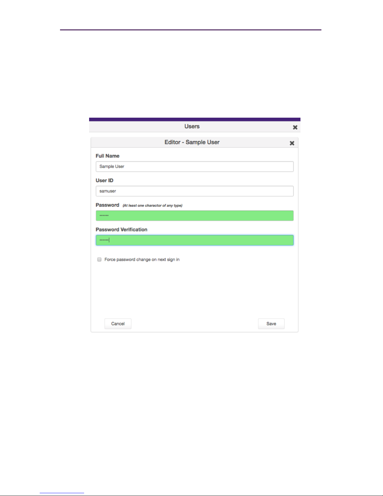
Click on the edit icon within the Admin user. The following screen will appear and al-
low you to change the password.
Page 53
46
Commands
Enter the new password on both the “Password” and “Password Validation” lines and then
hit the “Save” button in the lower right corner.
It is recommended to record this new password in a secure location.
Page 54
47
Commands
Adding a New User
To create a new user click on the “+” symbol in the Users window. The screen shown
below will appear. Enter the Full Name, User ID and Password for the new user. You can
keep this password or force the user to generate a new password the rst time they login
by clicking the “Force password change on next sign in” box.
Save the user by clicking the Save button in the lower right corner.
Page 55
48
Commands
Adding or Editing a Role
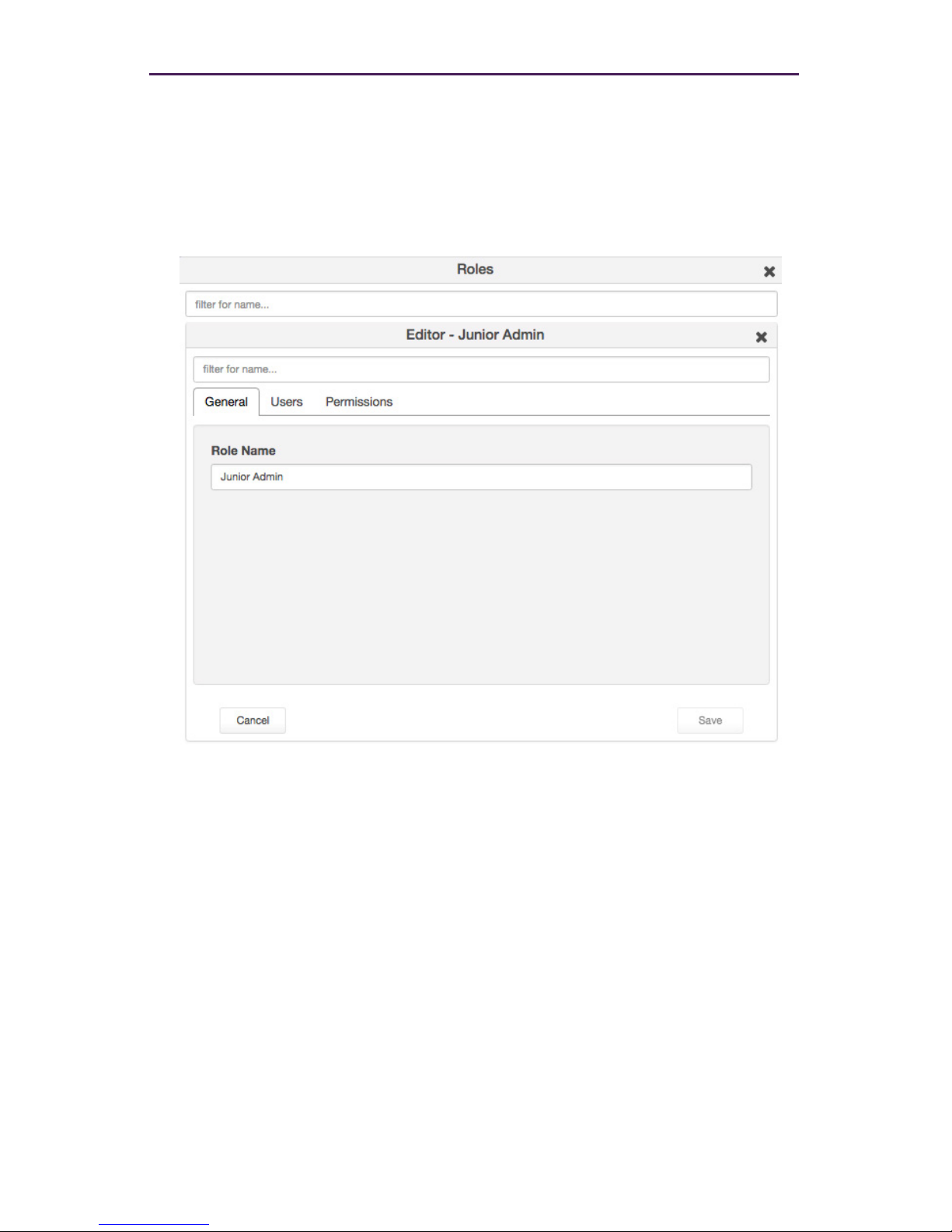
To create a new role click on the “+” symbol in the Roles window. The screen shown
below will appear. In the General tab enter the Role Name. In the example below the
name is “Junior Admin”.
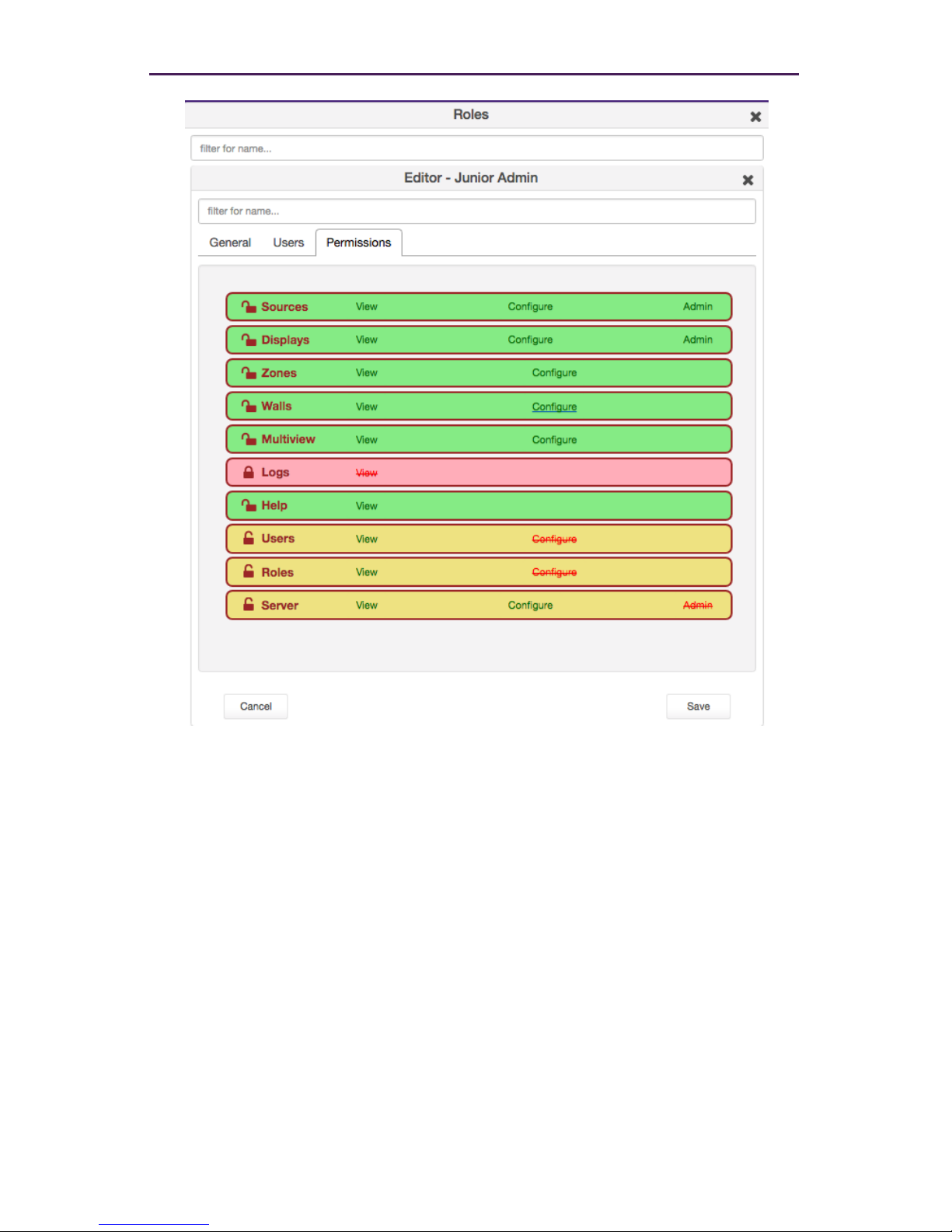
The next thing you will need to do is assign Permissions to this new role. To do this click on
the Permissions tab.
Page 56
49
Commands
There are 10 categories that can be assigined different levels of access within the
Permissions tab. Sources, Displays, Zones, Walls, Multiview, Logs, Help, Users, Roles and
Server. Most categories have 2 or 3 levels of access:
View: User is allowed to access the designated tab within MaestroZ
Cong: User is allowed to alter or create new congurations within the designated tab.
For example the user can create a new Wall, Multiview or Zone.
Admin: User has full functional control over conguraitons, including ability to delete
sources and displays.
Click on the appropriate levels of access to set permission. The process is color coded to
make it easier. Green = Full access, Yellow / Orange = Partial access, Red = No access.
Be sure to Save any changes before moving to the step of assigning specic users these
permission levels.
Page 57
50
Commands
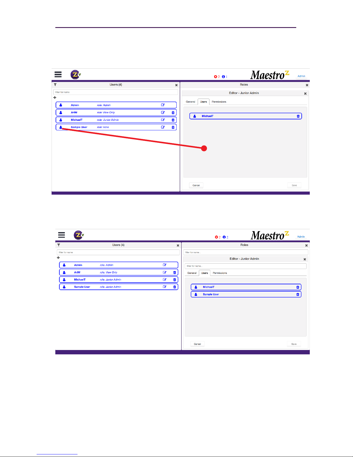
You need to have both the Users and Roles windows visible to assign a User with a set
of Roles / Permissions. Open the Users tab in the Roles window and drag a specic User
from the User window over. (Drag the “person” icon located to the far left next to user ID)
Be sure to Save any updates.
In example above, “Sample User” was dragged over to “Junior Admin” role.
Be sure to Save this setting before closing the Roles window.
Page 58

3 Advanced Operation
Page 59

52
Advanced Operation
Linux Server Management
In most circumstances, there is no need to directly modify the Linux conguration.
However, in some cases this may be necessary. A simple way to do this is to connect
using SSH (Secure Shell). On Mac OSX, this can be done through the Terminal
application. On Windows®, you will need to download and install an application that
contains an SSH client such as “PuTTY”.
Accessing Linux using SSH
1. Use the following command on a MAC or other Linux system.
Andrews-MacBook-Pro:~Andrew$ ssh zyper.local -l zyper
[email protected]’s password:
When entering the password, it will not be echoed to the screen.
2. Enter the password. The default password is admin. Once successfully connected,
information similar to the following will be displayed:
Andrews-MacBook-Pro:~Andrew$ ssh zyper.local -l zyper
[email protected]’s password:
Welcome to Ubuntu 14.04.2 LTS (GNU/Linux 3.16.0-49-generic
x86_64)
* Documentation: https://help.ubuntu.com/
455 packages can be updated.
239 updates are security updates.
Last login: Sat Feb 22 12:23:22 2016
zyper@zyper:~$
Making changes to the Linux operating system, which are not described
within this User Manual, may void the warranty and limit support options.
This includes the installation of third-party Linux software packages.
Page 60

53
Changing the Management Platform Password
To change the ZyPer account password, use the passwd command, as shown below.
Note that passwords are not echoed to the screen.
zyper@zyper:~$ passwd
Changing password for zyper.
(current) UNIX password:
Enter new UNIX password:
Retype new UNIX password:
passwd: password updated successfully
zyper@zyper:~$
Advanced Operation
Page 61

54
Advanced Operation
Accessing the API
Using Telnet
Telnet is a popular protocol that can be used on both Windows® and Mac OS® operating
systems to connect to the programming shell. On a Windows operating system, a Telnet
client, such as “PuTTY”, must be installed. From a Unix or Mac OS command line, use the
telnet command followed by the IP address of the Management Platform:
zyper@zyper:~$ telnet 192.168.1.6
Telnet will use port 23 by default and once connected, the API prompt will be displayed:
Zyper$
Getting Help
Help is available in two forms. Typing help or ? at the prompt will list all available
commands:
Zyper$ help
show server info
show server cong
set server timezone <posix-timezone-name:string>
set server auto-edid-mode enabled|disabled
set server api-password [<password:string>]
...
...
...
script <le-name> [loop]
sleep <millisecond-sleep:int>
Zyper$
In addition, a partial list of commands can be listed by specifying the rst word of each
command. The rst part of the command must be specied before the help command.
For example, the following will only list command with the join prex.
Zyper$ join help
join <encoder:macOrNameOrNone> <decoder:macOrName> genlocked
join <encoder:macOrNameOrNone> <decoder:macOrName> fast-switched
join <encoder:macOrName> <decoder:macOrName> analog-audio
Zyper$
Instead of specifying the IP address of the Management Platform, the
following identier can also be used: zyper.local
Example: telnet zyper.local
Page 62
55
Advanced Operation
Setting the Time Zone
The Management Platform uses the Network Time Protocol (NTP) to set the date and time.
However, the time zone will need to be specied.
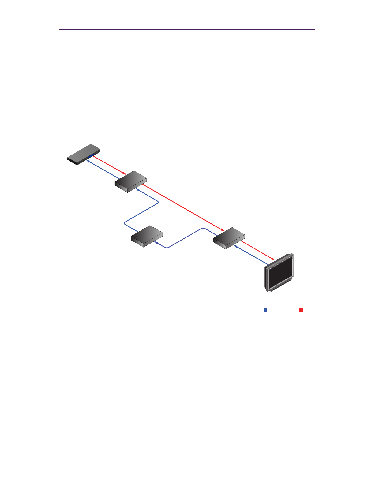
1. Telnet to the Management Platform.
zyper@zyper:~$ telnet 192.168.1.6
2. After the connection has been established, use the set server timezone
command to set the time zone.
Zyper$ set server timezone America/New_York
Success
Zyper$
Use the show server info command to verify the correct time zone has been set.
Zyper$ show server info
server(172.16.6.46);
server.gen; hostname=zyper.local, version=1.7.1.33348,
macAddress=40:8d:5c:32:44:cb, serialNumber=ZZM1FA00013A
server.gen; uptime=0d:19h:20m:23s, freeMem=6.406GB, bootCount=116
server.gen; runningInVm=false
server.ip-addressing; dhcp-allocated=true
server.time; time=Fri Dec 8 09:57:27 2017, timezone=America/
New_York
server.license; productID=038D0240-045C-0532-4406-CB0700080009,
license=none
server.license; limit=48, knownDevices=19, devicesUp=19, devices
Exceeded=0
server.deviceUpdates; active=0
server.activeDeviceVersions; num_2.11.3=8, num_2.11.4=3,
num_3.2.2=8
Success
Zyper$
The time zone must be specied in POSIX format and is case-sensitive.
Refer to the following link for more information:
http://wikipedia.org/wiki/List_of_tz_database_time_zones.
Page 63
56
Advanced Operation
EDID Management
Auto EDID Mode
By default, Auto EDID mode is enabled. This means that the Management Platform will
compare the encoder EDID with the decoder EDID. If they are different, then the EDID
from the decoder (sink) will be used by the encoder (source). Setting the EDID Mode
affects all join modes: fast-switched, genlocked, and video-wall. Refer to the join
command in the API Command Listing (page 61) section for more information.
Using Custom EDID Data
There may be some instances where a custom EDID is desired. One example is when
using a single encoder with multiple displays, such as a video wall. In such a case, follow
the steps below to save and load a custom EDID to the Management Platform.
1. Telnet to the Management Platform.
zyper@zyper:~$ telnet 192.168.1.6
2. Disable Auto EDID mode by entering the following command:
zyper$ set server auto-edid-mode disabled
Display/Projector
Zyper
Management
Platform
Encoder
Decoder
HD Source
EDID Data A/V Data
Page 64

57
Advanced Operation
3. Use the save device-edid command to save the EDID of the sink device (attached
to the decoder) to the Management Platform, using the following convention:
save device-edid [id] [lename]
Make sure to replace [id] with the identier of the sink device containing the EDID
you wish to capture. You can specify either a MAC address or a name identier.
Follow the identier with the name of the EDID le. For example:
zyper$ save device-edid SonyXBR4 myEDID
4. After executing this command, two les will be created under the following directory:
/srv/ftp/les/myEDID
/srv/ftp/les/myEDID.txt
myEDID is a binary EDID data le in standard format. myEDID.txt contains
the decoded EDID in standard ASCII text.
These les must remain in this directory when disabling Auto EDID mode.
5. To force a ZyPer encoder to use the saved EDID you need to have the MP load the
binary EDID le onto the desired encoder.
zyper$ load encoder-edid [id] [lename]
Make sure to replace [id] with the identier of the source device you want to load the
EDID onto. You can specify either a MAC address or a name identier.
Follow the identier with the name of the EDID le. For example:
zyper$ load encoder-edit BlueRay1 myEDID
6. To return to Auto EDID mode, for any reason, enter the following command at the
prompt:
zyper$ set server auto-edid-mode enabled
Page 65

58
Advanced Operation
Using AJAX/JSON
The AJAX/JSON programming interface allows developers to control the Management
Platform within browser-based applications. All calls to the server are asynchronous post/
receive operations using Javascript and do not require any specic HTML or CSS code.
We will present two examples in this section: Login authentication and command request/
response.
Login Authentication
There are two methods to authenticate with the server. The rst and recommended method
is to pass the username and password to rcLogin.php. The second method is to pass
the username and password in every AJAX request.
Once the server accepts the username and password, it will generate a secure cookie
called “userToken”. This cookie will expire one hour after the last AJAX command is
received by the server. After the cookie expires, all other AJAX requests will result in a
failed authentication until rcLogin.php is called again. The following code excerpt is from
the zyperLogin() function within zyper.html:
...
...
xmlhttp=new XMLHttpRequest();
xmlhttp.onreadystatechange = function(){
if (xmlhttp.readyState == 4 && xmlhttp.status == 200){
procLoginResp(xmlhttp.responseText);
}
}
postdata = “”;
postdata += encodeURIComponent(“serverSocketName”) + ‘=’ +
encodeURIComponent(socketName) + ‘&’ +
encodeURIComponent(“username”) + ‘=’ +
encodeURIComponent(username) + ‘&’ +
encodeURIComponent(“password”) + ‘=’ +
encodeURIComponent(password) + ‘&’;
xmlhttp.open(“POST”, url, true);
xmlhttp.setRequestHeader(“Content-Type”, “application/x-www-formurlencoded”);
xmlhttp.send(postdata);
}
The response is a string value. The variable resp can be “Success”, “Failed”, or “Server
not running”.
function procLoginResp(jsonData) {
var resp = JSON.parse(jsonData);
...
...
Page 66

59
Advanced Operation
Command Request / Response
The following code excerpt sends an AJAX request to list all ZyPer encoders and decoders:
function zt(){
xmlhttp = new XMLHttpRequest();
xmlhttp.open(“POST”, url, true);
xmlhttp.setRequestHeader(“Content-Type”, “application/x-www-formurlencoded”);
xmlhttp.onreadystatechange = function(){
if (xmlhttp.readyState == 4 && xmlhttp.status == 200){
procResp(xmlhttp.responseText);
}
}
xmlhttp.send(encodeURIComponent(“commands:show device-status
all”));
}
In this example, the encodeURIComponent function has two parts: The request type,
which is commands and the command show device-status all. Refer to the
show device status command for more information. Currently, commands is the
only request type that is supported and only a single command can be suppplied for each
request.
Here, we handle the AJAX response:
function procRespTest(jsonData){
var jsData = JSON.parse(jsonData);
# jsData.status may have the values:
# “Success”
# “Request failed authentication”
# “Server not running”
# “no commands provided”
#
if (jsData.status == “Success”){
var element = document.getElementById(“responseError”);
element.innerHTML = jsData.responses[0].error;
element = document.getElementById(“responseWarning”);
element.innerHTML = jsData.responses[0].warning;
element = document.getElementById(“numObjectsInResponse”);
element.innerHTML = jsData.responses[0].text.length;
}
else{
// Failed authentication
}
}
The JSON data is decoded using the JSON.parse() method. In this example, information
about the response data is displayed on the web page (HTML code not shown).
Page 67

60
Advanced Operation
The JavaScript object that is returned is:
var jsObj = {
status: true | false;
responses: [ {error: “errorText”,
warning: “warningText”,
text: [ { param1: “val1”, parmN: “paramN” } ]
}
]
};
The return value is an object that contains two members: status and responses.
If the status member is not equal to “Success”, then the responses member is not
valid. If the request fails authentication, then the status value will be “Request failed
authentication”. Note that there may be other web-server level failures that can be returned
in the status string.
The second member in the returned object, responses, which is an array of objects.
Each of these objects contains three members: error, warning, and text. The error
and warning members are strings. The text member is an array of objects with the
desired parameters and values. If the error string is non-null, then the warning and
text members will be null. If text is non-null, then the warning string may still be valid.
Currently, the responses member is always an array size of 1.
Page 68

61
Advanced Operation
API Command Listing
Command Description
create multiview
Creates a new multiview display (ZyPer4K
only)
create video-wall
Creates an empty 2x2 video wall.
delete all-conguration
Deletes all encoder/decoder and server
information from the Management Platform
delete device
Deletes the specied encoder or decoder
from the Management Platform database.
delete multiview
Deletes the specied multiview from the
Management Platform database. (ZyPer4K
only)
delete multiview-window
Deletes a specic window from an existing
multiview (ZyPer4K only)
delete video-wall
Deletes the specied video wall from the
Management Platform database.
factory-defaults device
Sets the specied encoder/decoder to
factory-default settings.
ash-leds
Plysically identies the specied encoder/
decoder on the network using LED ashes.
join
Switches audo and/or video from source to
display
load encoder-edid
Uploads an EDID le to the specied
encoder
redundancy switchover
Swap Management Platform Master and
Slave
restart device
Restarts the specied encoder/decoder
restart server
Restarts the Management Platform
restore device
Delete all the cong settings and restore
it based on the information stored in the
database.
save device-edid
Saves the EDID from a decoder to a local
le.
script
Executes the specied AJAX/JSON or text
script.
send
Sends an IR or RS232 string to the
specied device
Page 69

62
Advanced Operation
Command Description
set encoder analog-audio-out
source
Sets the source of Analog audio output
for specied encoder (ZyPer4K and
ZyPerUHD only)
set encoder hdcp-mode
Sets the hdcp compatibility at the encoder
side
set decoder display-mode
Sets default decoder output to crop, stretch
or box
set decoder display-size
Set decoder output size to auto or manual
resolution. (Width, Height, FPS)
set decoder analog-audio-out
source
Sets the source of Analog audio output for
specied decoder
set decoder hdmi-audio-out
source
Sets the source of HDMI audio output for
specied decoder
set device ethernet-management
port
Enables or disables the 1G Ethernet utiltiy
port for the specied device (ZyPer4K only)
set device general name
Sets the name for the specied device.
set device ip dhcp link-local
Sets the specied device to DHCP or LinkLocal mode (ZyPer4K only)
set device ip static
Sets the specied device to static mode
(ZyPer4K only)
set device rs232
Sets the RS232 setttings for the specied
device
set device send-ip-mcast-range
Sets allowable range of multicast
addresses for selected devices (ZyPer4K
only)
set device source-display
iconImageName
Sets the icon image for the specied
device.
set device source-display
location
Sets the location name for the specied
device.
set device source-display
manufacturer
Sets the manufacturer name for the
specied device.
set device source-display model
Sets the model name for the specied
device.
set device source-display
serialNumber
Sets the serial number name for the
specied device.
Page 70

63
Advanced Operation
Command Description
set device usb-lter
Allows restrictions to USB use on selected
device (ZyPer4K only)
set device video-port
Selects active input port for ZyPer4K units
with multiple inputs (ZyPer4K only)
set multiview
Assigns source to a position and size
within a multiview display (ZyPer4K only)
set multiview audio-source
window-number
Selects the input source to provide Audio
for multiview display (ZyPer4K only)
set responses rs232-term-chars
Species the RS232 termination string
set server auto-edid-mode
Sets the EDID mode
set server api-password
Sets the API password
set server license
Sets server license. (Max endpoints)
set server redundancy
Set a virtual IP address/mask for Master
and Slave Management Platforms
set server timezone
Sets the time zone
set video-wall
Creates a new video wall or modies an
existing wall
set video-wall decoder
Assigns the specied decoder to a position
within the video wall
set video-wall-encoder
Assigns the specied encoder to use a
source for the video wall
Page 71

64
Commands
Command Description
show device capabilities
Shows detailed capabilities of specied
device or devices
show device cong
Shows detailed conguration information
for specied device or devices
show device connections
Shows encoder connections to decoders
show device status
Provides detailed status informatoin for
specied device or devices
show multiviews cong
Lists all created multiviews with source,
position and size info (ZyPer4K only)
show multiviews status
Lists all created multiviews with source,
datarate and multicast address info
(ZyPer4K only)
show responses
Displays the lastChangeId for the specied
device
show server cong
Displays the IP address and EDID mode of
the Management Platform
show server info
Displays Management Platform information
show server redundancy
Displays information about Master and
Slave Management Platforms
show video-walls
Displays a list of all created video walls
shutdown server
Shuts down or reboots the Management
Platform
sleep
Sets a time dely, in milliseconds
stop encoder
Stop a specied stream
start encoder
Start a specied stream
switch
Switches IR or RS-232 between devices
trouble-report
Generates a trouble report
update device
Updates the individual encoder or decoder
unit
update server
Updates the Management Platform
software. See Updating the Software
(page 145) for more information.
Page 72

65
Commands
create multiview
Creates an empty multiview display. (ZyPer4K only) Once created, the new multiview will
be listed under the Multiview menu within the built-in Maestro Z.
Use the set multiview command to set a source encoder to a specied location and
size within the multiview.
Refer to Creating a Multiview Screen (page 33) for information on managing multiview
displays in the built-in Maestro Z.
Syntax
create multiview name
Parameters
name
Type: STRING
The name of the multiview. The name of the multiview cannot exceed
255 characters in length. Names are case-sensitive.
Example
create multiview myMultiview
Success
Related Commands
delete video-wallmultiview
delete multiview-window
set video-wallmultiview
set video-wall-decodermultiview audio-source window number
show multiviews cong
show multiviews status
Page 73

66
Advanced Operation
create video-wall
Creates an empty 2x2 video wall. Once created, the new video wall will be listed under the
Display Cong menu within the built-in Maestro Z.
Use the set video-wall-encoder command to assign a source encoder to the
wall. To modify the size of the video wall and/or control bezel parameters, use the
set video-wall command.
Refer to Creating Video Walls (page 28) for information on managing video walls in the
built-in Maestro Z.
Syntax
create video-wall name
Parameters
name
Type: STRING
The name of the video wall. The name of the video wall cannot exceed
255 characters in length. Names are case-sensitive.
Example
create video-wall myWall
Success
Related Commands
delete video-wall
set video-wall
set video-wall-decoder
set video-wall-encoder
Page 74

67
delete all-conguration
Deletes all device and server information from the Management Platform. The network
conguration is preserved.
Syntax
delete all-conguration action
Parameters
action
Type: STRING
Supply one of the following arguments before executing this command.
argument Description
reboot
Unit is automatically rebooted
restart
The ZyPer server service is restarted
shutdown
Unit is shutdown
Example
delete all-conguration restart
Related Commands
factory-defaults device
Advanced Operation
Page 75

68
delete device
Deletes the specied device from the Management Platform database.
Note that if the deleted device remains on the network, then it will be rediscovered by the
Management Platform and reposted to the database. To permanently remove a device
from the database, physically disconnected it and execute the delete device command.
Syntax
delete device id
Parameters
id
Type: STRING or MAC Address
The name or MAC address of the device. String names are case-sensitive.
Example
delete device myDevice
Success
delete device 0:1e:c0:f6:42:a1
Success
Related Commands
factory-defaults device
Advanced Operation
Page 76

69
Commands
delete multiview
Deletes the specied multiview from the database on the Management Platform. (ZyPer4K
only)
Syntax
delete multiview name
Parameters
name
Type: STRING
The name of the multiview. Names are case-sensitive.
Example
delete multiview myMultiview
Success
Related Commands
create video-wallmultiview
delete multiview-window
set video-wallmultiview
set video-wall-decodermultiview audio-source window number
show multiviews cong
show multiviews status
Page 77

70
Commands
delete multiview-window
Deletes the specied window from an existing multiview. (ZyPer4K only)
Syntax
delete multiview-window name window arg
Parameters
name
Type: STRING
The name of the multiview. Names are case-sensitive.
arg
Type: INTEGER
Window number to remove. Integer range from 1 to 9
Example
delete multiview-window myMultiview window 5
Success
Related Commands
create video-wallmultiview
delete multiview
set video-wallmultiview
set video-wall-decodermultiview audio-source window number
show multiviews cong
show multiviews status
Page 78

71
delete video-wall
Deletes the specied video wall from the database on the Management Platform.
Syntax
delete video-wall name
Parameters
name
Type: STRING
The name of the video wall. Names are case-sensitive.
Example
delete video-wall myWall
Success
Related Commands
create video-wall
set video-wall
set video-wall-decoder
set video-wall-encoder
Advanced Operation
Page 79

72
factory-defaults device
Set the specied device to the factory-default settings.
Syntax
factory-defaults device id
Parameters
id
Type: STRING or MAC Address
The name or MAC address of the device. String names are case-sensitive.
Example
factory-defaults device Airshow
Success
factory-defaults device 0:1e:c0:f6:a8:c3
Success
Related Commands
delete all-conguration
Advanced Operation
Page 80

73
ash-leds
Physically identies the specied device on the network. When this command is executed,
the ber LED indicators on the device will ash for 5 seconds.
Syntax
ash-leds id
Parameters
id
Type: STRING or MAC Address
The name or MAC address of the device. String names are case-sensitive.
Example
ash-leds myEncoder
Success
ash-leds 0:1e:c0:f6:59:13
Success
Advanced Operation
Page 81

74
join
Joins the specied decoder (display) with the specied encoder (source). The mode
parameter must be specied and denes the type of join to execute.
► analog-audio
Embeds audio stream from the encoder on the output of the decoder. The audio can
be from the HDMI input or from the (analog) Audio jack on the encoder.
In order to control what type of audio is being sent from an encoder, refer to the set
device command.
► fast-switched
Allows the joining of an encoder and decoder with no video dropout. In order to make
use of this feature, the resolution and frame rate of the “new” encoder must be the
same as the previous encoder.
► genlocked
This mode provides a very low-latency, all-purpose method of joining an encoder and
decoder.
► genlocked-scaled
This mode provides a very low-latency, all-purpose method of joining an encoder and
decoder that includes scaling up or down at the decoder/display.
► hdmi-downmix-audio
Embeds hdmi-downmix audio from an encoder to specied decoder.
► multiview
Join the congured multiview to a display (decoder) (ZyPer4K only)
► usb
Creates USB connection between encoder and decoder. Note that mulitple
connections are valid.
Syntax
join enc dec mode
Parameters
enc
Type: STRING or MAC Address
The name or MAC address of the encoder. String names are case-sensitive.
dec
Type: STRING or MAC Address
The name or MAC address of the decoder. String names are case-sensitive.
Advanced Operation
Page 82

75
mode
Type: STRING
Supply one of the following arguments before executing this command.
argument Description
analog-audio
Embed audio from the specied encoder
fast-switched
Join in “fast-switched” mode
genlocked
Low-latency join mode (ZyPer4K only)
genlockedscaled
Low-latency with scale up/down (ZyPer4K only)
hdmi-downmixaudio
Join hdmi-downmix-audio
multiview
Join in “fast-switched” mode (ZyPer4K only)
usb
Establish USB connection
Examples
join myEncoder1 myDecoder2 fast-switched
Success
join myMultiview2 Display4 multiview
Success
Advanced Operation
Page 83

76
load encoder-edid
Uploads an EDID le to the specied encoder.
Syntax
load encoder-edid enc le
Parameters
enc
Type: STRING or MAC Address
The name or MAC address of the encoder. String names are case-sensitive.
le
Type: STRING
The name of the le to load.
Example
load encoder-edid myEncoder myEDID.bin
Success
Related Commands
save device-edid
set server auto-edid-mode
Advanced Operation
Page 84

77
Commands
redundancy switchover
If there is an active slave, this command causes the existing master to become the slave
and the existing slave to become the master. The server does not restart or re-initialize any
other state, including any existing video and audio connections.
The IP address that is always assigned to the master. If the active slave becomes the
master, this IP address will then terminate at that system. Note that any existing TCP
connection will terminate and have to be reopened (to the new master).
Syntax
redundancy switchover
Parameters
none
Example
redundancy switchover
Success
Related Commands
set server redundancy
Page 85

78
restart device
Restarts the specied device.
Syntax
restart device id
Parameters
id
Type: STRING or MAC Address
The name or MAC address of the device. String names are case-sensitive.
Example
restart device myEncoder2
Success
restart device 0:1e:c0:f6:cb:76
Success
Related Commands
restart server
restore device
Advanced Operation
Page 86

79
restart server
Restarts the server. Linux is not restarted.
Syntax
restart server
Parameters
none
Example
restart server
Success
Related Commands
restart device
Advanced Operation
Page 87

80
Commands
restore device
Delete all the cong settings for specied device and restore it based on the information
stored in the database.
Syntax
restore device id
Parameters
id
Type: STRING or MAC Address
The name or MAC address of the device. String names are case-sensitive.
Example
restore device myEncoder2
Success
restart device 0:1e:c0:f6:cb:76
Success
Related Commands
restart serverdevice
Page 88

81
save device-edid
Saves the EDID of the downstream sink to the srv/ftp/les folder on the Management
Server. Executing this command will generate two le types: .bin and .txt. The .bin
le is the EDID is standard format. The .txt le is the decoded EDID data.
See Using Custom EDID Data (page 56) for more information on using this command.
Syntax
save device-edid id le
Parameters
id
Type: STRING or MAC Address
The name or MAC address of the decoder that is connected to the sink
device. String names are case-sensitive.
le
Type: STRING
The name of the EDID le. Two les will be created using the le name:
.txt and a le with no extension.
Example
save device-edid 0:1e:c0:f6:a5:2f myEDID
Success
Related Commands
load encoder-edid
set server auto-edid-mode
Advanced Operation
Page 89

82
script
Executes the specied script. The script must exist in the /srv/ftp/les folder.
Use the optional loop argument to place the script in a loop. The script will continue
running until a key is pressed on the keyboard.
Syntax
script le [loop]
Parameters
le
Type: STRING
The name of the script le.
Example
script myScript
Success
Related Commands
sleep
Advanced Operation
Page 90

83
send
Sends an IR or RS232 string to the specied device. Use the type parameter to specify
an IR or RS232 code.
Syntax
send id type text
Parameters
id
Type: STRING or MAC Address
The name or MAC address of the device.
type
Type: STRING
Species IR or RS232 command
argument Description
ir
The string must be the hex representation of the
binary data. The maximum length for a string is 256
characters.
rs232
The string is ASCII and must not exceed 256
characters in length. Spaces and the followng control
characters are supported as a portion of the string:
\n New line
\r Carriage return
\t Ta b
\\ Slash
\xnn Hex value, where nn is
a two-digit hex value, including
leading zeros
text
Type: STRING
The string to send. See the table, above, for restrictions.
Advanced Operation
Page 91

84
Example
send myDecoder2 ir 0000006900000015005f001700300017003000170030001
700300017001700170030001700170017001700170030001700170017003000170
030001700170017003000170017001700170017001700170030001700300017003
00200
Success
send myDecoder2 rs232 ZeeVee_support_is_the_greatest\r\n
Success
Related Commands
set device rs232
Advanced Operation
Page 92
85
Commands
set encoder analog-audio-out
Sets the analog audio output source type for the specied encoder. (ZyPer4K and
ZyPerUHD only)
Syntax
set encoder id mode type
Parameters
id
Type: STRING or MAC Address
The name or MAC address of the encoder. String names are case-sensitive.
mode
Type: STRING
The audio output to use.
argument Description
analog-audio-out
Audio output from the Audio port on the Encoder.
type
Type: STRING
The audio mode (analog or HDMI).
argument Description
source none
No analog audio output from the encoder
source hdmidownmix
Uses downmixed audio from input HDMI stream.
Example
set encoder Myencoder1 analog-audio-out source hdmi-downmix
Success
Page 93

86
Commands
set encoder hdcp-mode
Sets the hdcp mode for the specied encoder.
Syntax
set encoder id mode type
Parameters
id
Type: STRING or MAC Address
The name or MAC address of the encoder. String names are case-sensitive.
mode
Type: STRING
The hdcp mode to use
argument Description
hdcp-mode
HDCP mode of the Encoder.
type
Type: STRING
The audio mode (analog or HDMI).
argument Description
enabled
encoder will accept HDCP 1.4/2.2 compatible
streams
disabled
encoder will reject HDCP 1.4/2.2 compatible streams.
Example
set encoder Myencoder1 hdcp-mode disabled
Success
Notes
Useful when user does not want Source such as Apple Macbook to
provide HDCP protected content to the Encoder.
Page 94

87
set decoder
Sets the audio output type and video timing details for the specied decoder.
Syntax
set decoder id mode type
Parameters
id
Type: STRING or MAC Address
The name or MAC address of the decoder. String names are case-sensitive.
mode
Type: STRING
argument Description
analog-audio-out
Audio output from the Audio port on the decoder.
display-advanced-timing
Set advanced features, Front porch, sync width, sync
polarity and total size
display-aspect-ratio
display-mode
Set display to box, crop or stretch input stream within
display resolution
display-size
Set display size manually (pixels) or automatically
based on EDID.
hdcp-mode
Allows user to force HDCP protection at level 1.4 or
2.2 on previoulsy unprotected content.
hdmi-audio-out
Audio output from the HDMI port on the decoder.
type
Type: STRING
HDCP options. (Note: Valid with ZyPerUHD only) Used to minimize connection time.
argument Description
auto
Maintain existing HDCP level. None if none
force-version-1.4
Apply HDCP 1.4 protection to output stream
force-version-2.2
Apply HDCP 2.2 protection to output stream
Advanced Operation
Page 95

88
Commands
The audio mode (analog out or HDMI out).
argument Description
source analog
Uses the audio output created with the join
command.
source hdmi
Uses the HDMI stream (HDMI audio-out only)
source none
No audio output
source hdmidownmix
Uses the HDMI-downmix stream.
Display timing, aspect ratio, mode, size.
argument Description
sync-front-porch
Synchronization mode.
sync-width
Synchronization width
hsync-polarity
Horizontal sync polarity (auto, negative, positive)
vsync-polarity
Vertical sync polarity (auto, negative, positve)
total-size
Horizontal and vertical size (Pixels or auto)
box
Box image within display. (Smaller source to larger
display)
crop
Crop image within dispaly (Larger source to smaller
display)
stretch
Scale image to ll display. (Scale up or down)
(Default Setting)
width
Width in pixels or auto
height
Height in pixels or auto
fps
Frames per second
auto
automatically based on EDID
Command Desciption: Override output display size and fps
set decoder <Decoder_Name or MAC> display-size width <int> height <int> fps <int>
This command allows an override of EDID parameters supplied by the display. Regardless
of what the supplied EDID indicates, the decoder will generate a stream with specied overall size
and frame rate parameters.
Note that in “genlock-scaled” mode, the frame rate parameter is ignored – it must be the
same as the encoder frame rate. This does mean care must be taken when setting this parameter if
the source stream is 60fps (e.g. 720p60fps) and scaled to 4K. That only works if the display supports
4K60.
If congured resolution specication in these parameters that exceed the displayed
maximum resolution, the display will black out with no indication to the user.
Page 96

89
Commands
Example command on the API:
Zyper$ set decoder DF-BR1 display-size width 1280 height 720 fps 60
Command Description: Output display size determined by received EDID
Command Syntax
set decoder <Decoder_Name or MAC> display-size auto
The command causes the decoder to set output display size to the
“preferred” value in the EDID received from the display.
Command Description: Override detailed video parameters
Command Syntax
set decoder < Decoder_Name or MAC > display-advanced-timing
sync-front-porch <pixelsHoriz:int>|auto <pixelsVert:int>|auto sync-width
<pixelsHoriz:int>|auto <pixelsVert:int>|auto
hsync-polarity positive|negative|auto
vsync-polarity positive|negative|auto
total-size <pixelsX:int>|auto <pixelsY:int>|auto
This command allows an override of EDID parameters supplied by the
display. Regardless of what the supplied EDID indicates, the decoder will
generate a stream with specied detailed timing parameters.
If congured resolution specication in these parameters that exceed
the displayed maximum resolution, the display will black out with no
indication to the user.
Example command on the API:
Zyper$ set decoder jagd-e1 display-advanced-timing
sync-front-porch 176 8
sync-width 88 10
hsync-polarity positive vsync-polarity positive
total-size 4400 2250
Page 97

90
Commands
set device ethernet-management-port
Enables or disables the 1Gb Utility Ethernet port on the specied encoder or decoder.
(ZyPer4K only)
Syntax
set device id ethernet-management-port arg
Parameters
id
Type: STRING or MAC Address
The name or MAC address of the device. String names are case-sensitive.
arg
Type: STRING
Supply one of the following arguments.
argument Description
enabled
Ethernet port is enabled.
disabled
Ethernet port is disabled.
Example
set device myDecoder5 ethernet-management-port disabled
Success
Related Commands
set device analog-audio mode
set device general name
set device ip
set device rs232
set device source-display iconImageName
set device source-display location
set device source-display manufacturer
set device source-display model
set device source-display serialNumber
Page 98

91
Advanced Operation
set device general name
Sets the name for the specied encoder or decoder.
Syntax
set device id general name str
Parameters
id
Type: STRING or MAC Address
The name or MAC address of the device. String names are case-sensitive.
str
Type: STRING
The name for the device.
Example
set device myDecoder5 general name Samsung-55
Success
Related Commands
set device analog-audio mode
set device gig-ethernet-port mode
set device ip
set device ip static
set device rs232
set device source-display iconImageName
set device source-display location
set device source-display manufacturer
set device source-display model
set device source-display serialNumber
Page 99

92
Advanced Operation
set device ip
Sets DHCP mode for the specied device. (ZyPer4K only)
Syntax
set device id ip arg
Parameters
id
Type: STRING or MAC Address
The name or MAC address of the decoder. String names are case-sensitive.
arg
Type: STRING
Supply one of the following arguments.
argument Description
dhcp
IP address assigned by DHCP server
link-local
IP address self assigned Link-Local
Example
set device ip dhcp
Related Commands
set device analog-audio mode
set device general name
set device gig-ethernet-port mode
set device ip static
set device rs232
set device source-display iconImageName
set device source-display location
set device source-display manufacturer
set device source-display model
set device source-display serialNumber
Page 100

93
Advanced Operation
set device ip static
Sets static mode for the specied device. The IP address, subnet mask, and gateway must
be supplied. (ZyPer4K only)
Syntax
set device id ip static addr mask gatew
Parameters
id
Type: STRING or MAC Address
The name or MAC address of the decoder. String names are case-sensitive.
addr
Type: IP Address
The desired IP address for the device.
mask
Type: IP Address
The desired subnet mask for the device.
gatew
Type: IP Address
The desired gateway for the device.
Example
set device ip static 10.5.68.121 255.255.255.0 10.5.64.1
Success
 Loading...