

Page 1
Module
Get Going Guide
HDbridge modules are HD MPEG-2 Encoders
and frequency-agile QAM Modulators. They
allow you to convert any component HD video
source, in real-time and very high quality into
an HDTV cable channel. This channel is placed
onto standard coax wiring, where it can be
combined with up to 134 other HDTV channels
and distributed over an entire premise.
Modules are deployed in the HDbridge Rack
Chassis, where they are provided power and
an RF port into which they broadcast.
This guide will take you through setting up an
individual module. For additional assistance
or more complex installations, please refer to
the ZeeVee Support page at www.zeevee.com,
where you will nd answers to frequently asked
questions and helpful tips from ZeeVee experts.
If you cannot nd the answers you need, our
technical support hot line at 877-4ZEEVEE
(877-493-3833) is here to help.
Page 2
Important Safety Instructions
1. Read these instructions.
2. Keep these instructions.
3. Heed all warnings.
4. Follow all instructions.
5. Do not use this apparatus near water.
6. Clean only with dry cloth.
7. Do not block any ventilation openings. Install in accordance with the
manufacturer’s instructions.
8. Do not install near any heat sources such as radiators, heat registers,
stoves, or other apparatus (including ampliers) that produce heat.
9. Do not defeat the safety purpose of the polarized or grounding-type plug.
A polarized plug has two blades with one wider than the other. A grounding type plug has two blades and a third grounding prong. The wide blade
or the third prong is provided for your safety. If the provided plug does not
t into your outlet, consult an electrician for replacement of the obsolete
outlet.
10. Protect the power cord from being walked on or pinched, particularly at
plugs, convenience receptacles, and the point where they exit from the
apparatus.
11. Unplug this apparatus during lightning storms or when unused for long
periods of time.
12. Only use attachments/ accessories specied by the manufacturer.
13. Refer all servicing to qualied service personnel. Servicing is required when
the apparatus has been damaged in any way, such as power-supply cord
or plug is damaged, liquid has been spilled or objects have fallen into the
apparatus, the apparatus has been exposed to rain or moisture, does not
operate normally, or has been dropped.
FCC Statement
FCC Compliance and Advisory Statement: This hardware device complies with Part 15 of the FCC
rules. Operation is subject to the following two conditions: 1) this device may not cause harmful
interference, and 2) this device must accept any interference received including interference that may
cause undesired operation. This equipment has been tested and found to comply with the limits for
a Class B digital device, pursuant to Part 15 of the FCC Rules. These limits are designed to provide
reasonable protection against harmful interference in a residential installation. This equipment generates, uses, and can radiate radio frequency energy and, if not installed or used in accordance with the
instructions, may cause harmful interference to radio communications. However there is no guarantee
that interference will not occur in a particular installation. If this equipment does cause harmful
interference to radio or television reception, which can be determined by turning the equipment off
and on, the user is encouraged to try to correct the interference by one or more of the following measures: 1) reorient or relocate the receiving antenna; 2) increase the separation between the equipment and the receiver; 3) connect the equipment to an outlet on a circuit different from that to which
the receiver is connected; 4) consult the dealer or an experienced radio/TV technician for help. Any
changes or modications not expressly approved by the party responsible for compliance could void
the user’s authority to operate the equipment. Where shielded interface cables have been provided
with the product or specied additional components or accessories elsewhere dened to be used with
the installation of the product, they must be used in order to ensure compliance with FCC regulations.
Page 2 of 8 www.zeevee.com
Page 3
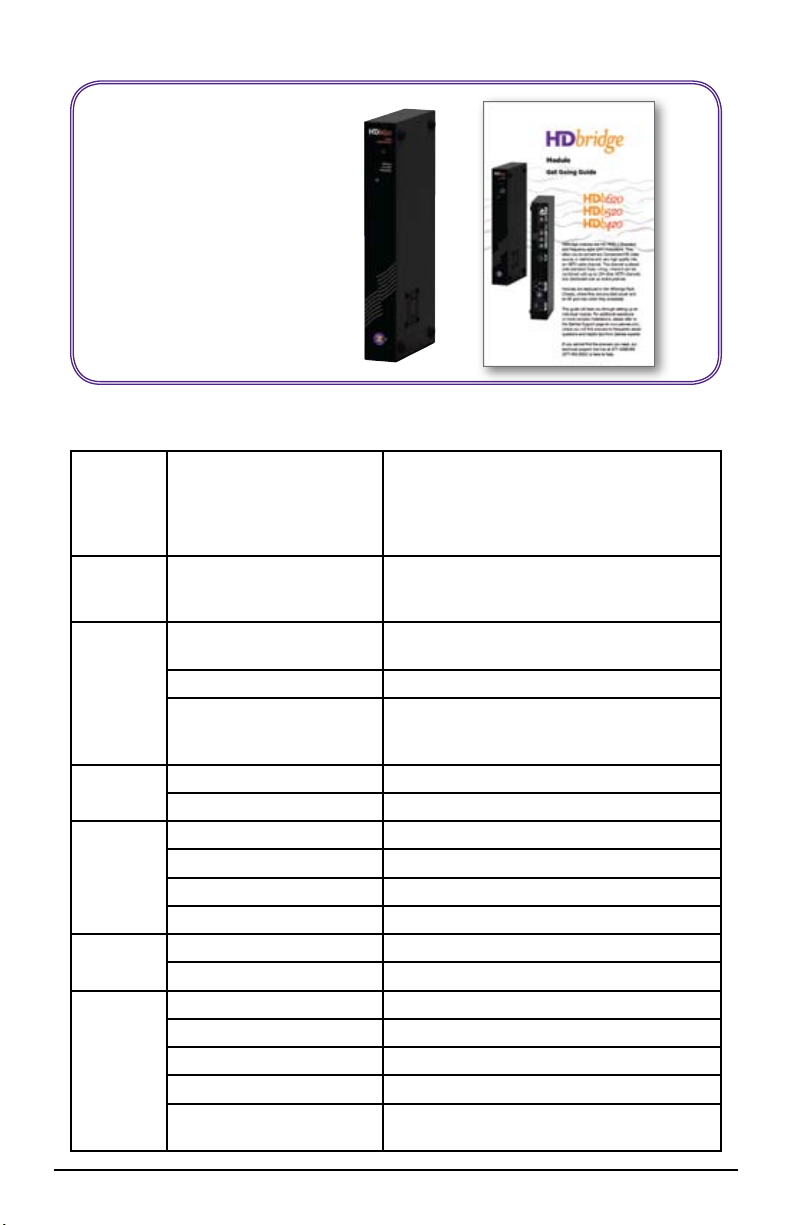
What’s in the Box
HDbridge Module•
Get Going Guide•
Note - Modules are deployed
using the HDbridge Rack Chassis,
part number HDb-RK1
Specications
Inputs Component Video
Video
Encoder
Audio PCM encoding AC-3, ATSC A/52
RF
Output
Power DC Input +12V, 1.6A
Physical Width 1.7 Inches
(Y, Pb, Pr)
RCA connectors
S/PDIF Digital Audio
RCA connection
Optical connection
Encoder Video Prole MPEG2 HD Prole 2: ISO13802
Video Transport Bit Rate 38.78 Mbps
Avg Encoding Data Rate HDb620 - 35Mbs
Digital Pass-through Dolby Digital
Modulation Type (Americas) QAM 256, QAM 64 (ITU-T J83 Annex B)
Cable Standards HRC, IRC, or STD (default)
Frequency Range 50-900 MHz (channels 2-135)
Module Output Power +25dBmV typical
Radio Emissions FCC Home or Ofce (B)
Height 10.5 Inches
Depth 4.75 Inches
Product Weight 0.95 Kg (33.5 Oz.)
Temperature/Humidity Operating +32F to +104F (0C to +40C) /
Resolutions Supported
HDb620 - 1080p, 1080i, 720p, 480p, 480i
HDb520 - 720p, 480p, 480i
HDb420 - 480p, 480i
All at 59.94 frames/elds per second
Formats
48K, 44.1k, 32k bit PCM•
AC-3 Pass-through•
MP@HL (1920x1080, 1280x720)
HDb520 - 28Mbs
HDb420 - 14Mbs
©
(AC-3) 1 to 5.1 channel
20% to 80%, non-condensing
HDbridge Get Going Guide Page 3 of 8
Page 4

Getting Started
Front Panel
1
Back Panel
3
4
2
5
6
7
8
9
10
Description Function
1 LED Signals the activity. Also used in programming
2 Setup Button For setting broadcast channel
The LED shows solid blue during normal operation. During startup it will show:
Fast ashing blue/yellow (~20 cycles), followed by fast blue blink (~100 cycles),
followed by slow blue blink (~40 cycles), followed by solid blue that blinks twice after
30 seconds and returns to a solid blue. Video transmission begins when the LED
becomes solid blue. Continuous blue/yellow ashing LED indicates trouble found during
boot-up.
Description Function
4 RF Coax Output Encoded video as a well-formed QAM channel
5 S/PDIF audio input, RCA Accepts digital audio input (PCM or AC3)
6 S/PDIF audio input, Optical Accepts digital audio input (PCM or AC3)
7 Component Video input RCA connectors, 75 Ohm. Y, Pr, Pb
8 LAN Control Web interface for conguration
9 DC Power DC power input, 12 volt
10 Reset Restores factory defaults
To restore factory defaults ... Remove the power. Depress and hold the reset
button in the back of the unit. Reapply power. LED will ash blue/yellow (~20 cycles),
followed by fast blue blink (~20 cycles), followed by *solid yellow*. Release the reset
button. The unit will then restore all factory defaults and go through a full reboot.
Page 4 of 8 www.zeevee.com
Page 5

Back of HDbridge Module
S/PDIF
Audio
Cable
Basic Installation
Audio Out
Video Out
Component
Video Cable
Coax Cable
HDbridge
Rack Chassis
HDb-RK1
HD Source
Power
Factory default settings allow your module to broadcast a component HD source with
digital audio on Channel 2.1, over coax cabling, for reception at connected HDTVs.
Connect DC power from the rack chassis into the module.1.
Connect Component Video and Digital Audio of an HD source.2.
Connect Coax output to the HDTV RF input.3.
Tune the HDTV to channel 2.1 to view your new Zv channel.4.
Conguration and rmware updates are done via a web interface. Connect the LAN port
directly to a PC using a standard Ethernet cable. In a few minutes, your PC will recognize
the device and will present it under “Network” or “Network Places.” Double-click on the icon
(its name will be the unit’s serial number). The web interface will open up in your browser
and display the login page. The default Username is “admin” and Password is “admin.” (You
can change the Password but not the Username.) Once you log in, the interface will take
you through the conguration. The broadcast channel also can be set via a front-panel
button as described on the next page. Note: Windows XP users must have UPnP installed
on their computer. Go to www.zeevee.com/FAQ for more information.
For help with installing your HDbridge Module onto a coax network, please see our
tutorials, found on the ZeeVee web site: www.zeevee.com/support/training.
HDbridge Get Going Guide Page 5 of 8
Page 6

Configuration
Valid Channels
CATV 2-135. RF Channel 2 and Digital channel 2.1 is the factory setting.
Channel Spacing
None required. Channels can be set directly adjacent to any other well-formed channel and will not cause interference.
Tuning in your channel at the HDTV
Typically just enter the channel number that you have programmed (2 is the default).
Tuning may take a few seconds. If the channel is not found, try entering your channel
number followed by a “-1” or “.1”. For example, “2.1”. You may also need to perform
a channel scan. If so, make sure you select Cable Mode (not Antenna or Air Mode).
Your HDbridge module gives you the option to congure many items, including
broadcast channel, channel name, digital watermarks, data-rates, and many other
settings. This is accomplished by using a web interface accessible through the LAN
port.
To simplify installation, the only setting that must be done is the broadcast channel.
It’s possible to perform this using the LED and button on the front of the unit.
Unlocking the Setup Button
After the unit boots up, it is ready for channel setup when the LED begins to show a
steady blue. At that point, if channel setup is not started within 30 seconds, the LED
will ash twice and the unit will lock to prevent accidental reprogramming.
If the unit is locked, the LED will continue to show a steady blue even when the
button is pressed.
To unlock, press and hold the button until the LED ashes twice (approx. 5 seconds).
The LED will then ash the current channel. The unit is now ready for programming.
Once unlocked, the unit will re-lock automatically if there is no activity within 30
seconds.
Page 6 of 8 www.zeevee.com
Page 7

Configuration
Setting the channel via the Setup Button on the unit front
1.Wait for steady blue LED to indicate the
unit is ready for programming. Verify the
unit is unlocked. (Refer to “Unlocking
the Setup Button.”)
2.Digits are entered from left to right. Just
start entering them.
3. Each digit is entered by pressing the
button multiple times. A “zero” is
entered as 10 presses.
4.Wait for the LED to blink blue
between digits.
5. After all digits are entered, wait a few
seconds and the programmed channel
number is played back.
The LED will blink red if an improper channel was selected. The original value
is restored.
If the channel is valid, the broadcast is changed before playing back the new
channel.
Example: Programming Channel 50
Press the Button 5 times. The
LED blinks YELLOW at each press
Wait for the LED to ash BLUE
once
Press the Button 10 times
Wait for the LED to ash BLUE
once. Wait 5 more seconds (exits
channel setting mode)
The system will play back the
new channel number
To read back the current channel (assume it is 67)
Press and Hold the button until the LED turns yellow, and then blue again
- Release the button
The LED will ash yellow twice per second SIX times
There will be a two second pause
The LED will ash yellow twice per second SEVEN times
The LED will return to a steady blue.
Changing Modulation Standards:
Cable STD, HRC and IRC channel plan considerations: Most cable services program
their channel placements using a Standard (STD) channel lineup. In increasingly
rare cases, HRC or IRC channel placements are used. The modulator can be reprogrammed to use these standards by entering the following channel numbers using
the channel programming procedure:
STD Channel 205
HRC Channel 206
IRC Channel 207
HDbridge Get Going Guide Page 7 of 8
Page 8

Troubleshooting
No Picture ... Verify the HDTV has a QAM (digital cable) tuner. Verify that you have
performed a full channel scan on the HDTV with “cable mode” selected. Verify that
the modulator is not conicting with any other channel by connecting the HDbridge
Module directly to the HDTV.
Idle Screen (bouncing logo) ... This happens because the modulator cannot
detect the video source. Verify the source is on and producing a video signal. Verify
that the component cable is connected to the source and modulator correctly. Verify
that the green connector is in the green port, blue connector in the blue port, and red
connector in the red port.
Image Breakup ... You may have chosen a channel number that is not completely
vacant. Some analog modulators may spill over to adjacent channels and cause
interference. Also, cable companies sometimes have extra signals where there should
be none. Try moving the module channel to another location.
You may be experiencing an RF power balance issue. Verify that the RF power of
the modulator is balanced with signals from other modulators and from the cable
company.
Your HDTV may not be able to play the high data rate that the HDbridge module
produces during fast action. Lower the data rate via the web interface.
1080 or 720 video input is not supported on this product ... This message is
displayed on the screen when the video source resolution exceeds the capability of
your HDbridge module. Set the video source to the the appropriate resolution.
No Audio ... Verify that digital audio is connected to the modulator and to the source.
Verify that the source audio output is set to PCM or AC-3.
Contact ZeeVee
For support, repairs, and warranty service ............877-4ZEEVEE (877-493-3833)
For purchasing and sales inquiries .................978-633-ZVHD (978-633-9843)
Warranty
Limited One Year Warranty: ZeeVee warrants your HDbridge Module against defects in materials
and workmanship for a period of one year from the date of purchase. Visit www.zeevee.com for
complete warranty details.
To Get Warranty Service: Warranty service will be provided by ZeeVee. If you believe you need ser-
vice for your product, please contact ZeeVee directly by calling ZeeVee Support at (877) 493-3833.
If it is determined that the product needs to be returned for service or exchange, you will receive a
Return Material Authorization (“RMA”) number. Our agents will help you through the process through
which you can return the product. ZeeVee is not responsible for Customer products received without
an RMA number and may reject such products.
To Get Out-Of-Warranty Service: To obtain out-of-warranty service for your product please call
ZeeVee Support at (877) 493-3833 for information on the possibility of and any costs for repair or
replacement of out-of-warranty products. No agent, company, dealer, distributor, or person is
authorized to change, modify, or extend the terms of these warranties in any manner.
ZeeVee, Inc. • One Monarch Drive • Littleton, MA 01460 • info@zeevee.com
rev.2
 Loading...