

Page 1

HDbridge
Advanced Configuration Manual
Deploying Digital Signage Page | 1
The Case for Coax
Page 2

Contents
Getting Started with HDbridge ................................................................................................. 3
RF Rules Apply ........................................................................................................................... 3
Rack Chassis – RK1 or RK2 ......................................................................................................... 3
Installing Modules in the Rack Chassis ..................................................................................... 3
Basic Configuration (Front Panel) ............................................................................................. 4
Channel Spacing ........................................................................................................................ 4
Unlocking the Setup Button ...................................................................................................... 4
Setting the Channel via the Front Panel Button ....................................................................... 4
Changing Modulation Standards .............................................................................................. 5
Restoring Factory Defaults ........................................................................................................ 5
Advanced Configuration Using WebManager ............................................................................ 5
Logging in to WebManager ....................................................................................................... 6
Navigating in WebManager ...................................................................................................... 6
Summary Tab ............................................................................................................................ 7
Configuration Tab ..................................................................................................................... 7
RF & HDTV Channel ................................................................................................................... 8
RF & HDTV Channel (continued) ............................................................................................... 9
Audio / Video .......................................................................................................................... 10
MPEG Encoding ....................................................................................................................... 11
IP Configuration ...................................................................................................................... 11
Password Management .......................................................................................................... 12
Status Tab ................................................................................................................................ 12
System Status .......................................................................................................................... 12
Audio/Video Status ................................................................................................................. 13
Actions Tab .............................................................................................................................. 13
Firmware Update Tab ............................................................................................................. 14
Troubleshooting ..................................................................................................................... 15
Contact ZeeVee ...................................................................................................................... 15
Warranty ............................................................................................................................... 15
HDbridge™ Module Configuration Manual Page 2
www.zeevee.com Rev 1.0
Page 3
RK1
RK2
Provided
Power for 8 modules
8-way RF combiner
RF amplifier
Launch power is 34db
Power for 8 modules
RF output of each module is 25db
Not Provided
Component cables
Digital Audio cables (optical or spdif)
Ethernet
8-way RF combiner
RF amplifier
Component cables
Digital Audio cables (optical or SPDIF)
Ethernet
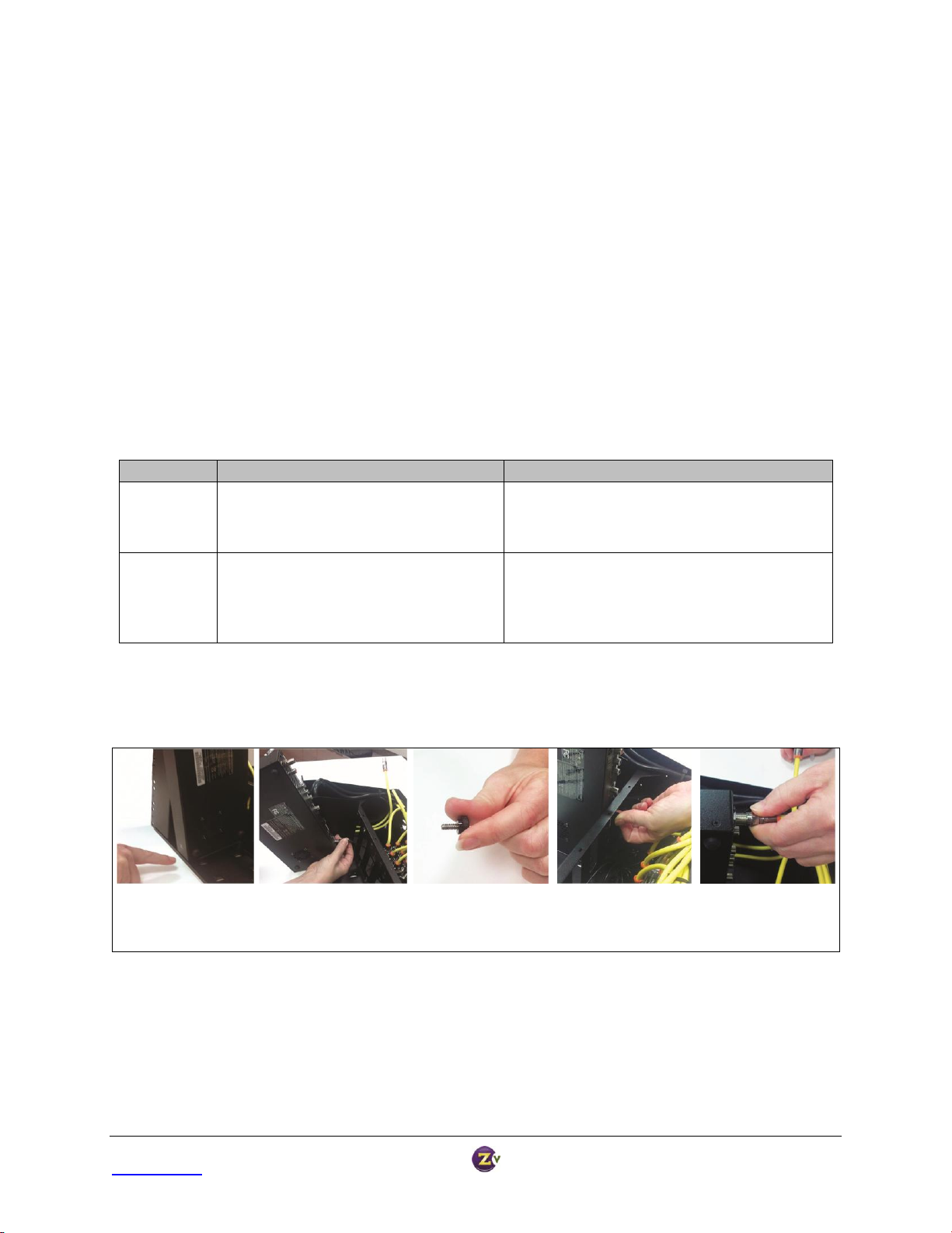
Align module inside the
small lip on the chassis.
Insert the DC power plug into
the module. Push down on
the module until it sits flat.
Locate the thumbscrew
in the bracket behind
the module.
Tighten the thumbscrew
into the module until
it is snug.
Attach the coax snugly to
the RF output connector
on the module.*
*RK2 users need to provide their own coax connections.
Getting Started with HDbridge
RF Rules Apply
Treat the HDbridge system the same way as any other RF system. Each modulator (or “module”) outputs a QAM
signal that works with off-the shelf RF tools, equipment, and materials.
Each module requires a full RF channel.
Each display must have a QAM tuner.
RF power output from each module must be balanced with existing modulators/feeds.
Standard calculations for distance and power apply.
Rack Chassis – RK1 or RK2
HDbridge modules mount into the HDb Rack Chassis for easy installation. For more flexibility, there are two Rack
Chassis to choose from:
Installing Modules in the Rack Chassis
The Rack Chassis mounts up to eight modules, with thumb screws to secure them to the rack.
Connect the Component and Digital Audio cables from the source. Connect Ethernet cables for advanced
configuration. Refer to the HDbridge Rack Chassis Get Going Guide for detailed instructions on module installation.
HDbridge™ Module Configuration Manual Page 3
www.zeevee.com Rev 1.0
Page 4

Basic Configuration (Front Panel)
Digits are entered from left to right.
Each digit is entered by pressing the front panel
button multiple times. A “zero” is entered as 10
presses.
Wait for the LED to blink blue between digits.
After all digits are entered, wait a few seconds and
the programmed channel number is played back.
o The LED will blink red if an improper channel
was selected. The original value is restored.
o If the channel is valid, the broadcast is
changed before playing back the new channel.
Example: Programming Channel 50
Press the Front Panel Button 5 times. The
LED blinks YELLOW at each press.
Wait for the LED to flash BLUE once.
Press the Front Panel Button 10 times.
Wait for the LED to flash BLUE once.
Wait 5 more seconds (exits channel setting
mode).
The system will play back the new channel
number.
Factory default settings allow your module to broadcast a component video source with digital audio on Channel
2.1. Tune the HDTV to channel 2.1 to view your new Zv channel.
Channel Spacing
None required for digital channels. Channels can be set directly adjacent to each other and any other well-formed
digital channels and will not cause interference. Spacing may be necessary when combining with other modulated
analog channels.
Unlocking the Setup Button
After the unit boots up, it is ready for channel setup when the LED begins to show a steady blue. At that point, if
channel setup is not started within 30 seconds, the LED will flash twice, and the unit will lock to prevent accidental
reprogramming.
If the unit is locked, the LED will continue to show a steady blue even when the button is pressed.
To unlock, press and hold the button until the LED flashes twice (approximately 5 seconds). The LED will then flash
the current channel. The unit is now ready for programming.
Once unlocked, the unit will re-lock automatically if there is no activity within 30 seconds.
Setting the Channel via the Front Panel Button
RF and HDTV channels can be changed using just the front panel button, no PC or Ethernet connection is required.
When using the Front Panel Button for configuration, RF and HDTV channels are linked; for example RF channel 50
will be HDTV channel 50.1. To change the HDTV channel or to make other changes, refer to the Advanced
Configuration section on pages 8-9.
To read back the current channel (assume it is Channel 50):
Press and Hold the button until the LED turns yellow, and then blue again. Release the button.
The LED will flash yellow twice per second FIVE times.
There will be a two second pause.
The LED will flash yellow twice per second TEN times.
The LED will return to a steady blue.
HDbridge™ Module Configuration Manual Page 4
www.zeevee.com Rev 1.0
Page 5
STD
Channel 205
HRC
Channel 206
ORC
Channel 207
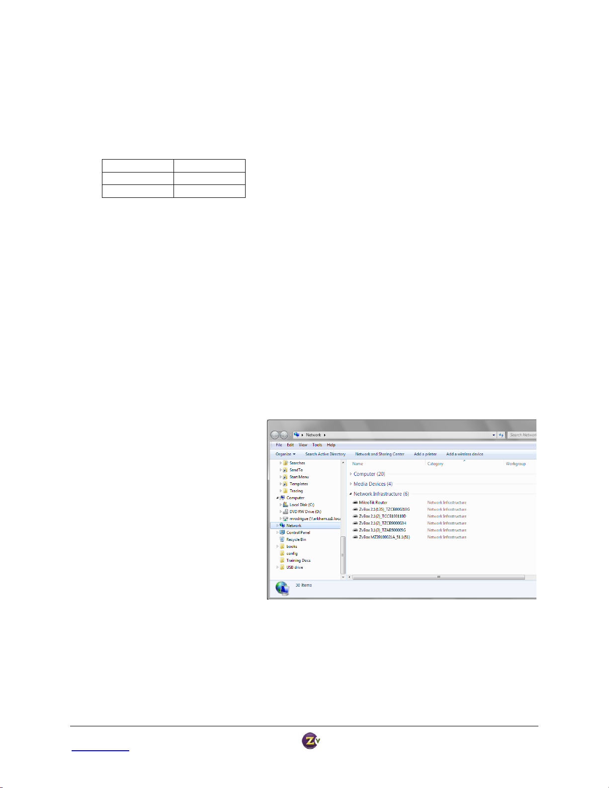
If the units are not displayed:
Verify that Universal Plug and Play
(UPnP) is installed on your
computer. In Windows 7, UPnP is
enabled by default but Windows
XP users may need to
download/install it.
Verify Network Discovery is
enabled.
Change to DHCP instead of a static
IP address.
For additional information and
troubleshooting steps see the FAQ
section on www.zeevee.com.
Changing Modulation Standards
Cable STD, HRC, and IRC channel plan considerations: Most cable services program their channel placements using
a Standard (STD) channel lineup. In increasingly rare cases, HRC or IRC channel placements are used. The
modulator can be reprogrammed to use these standards by entering the following channel numbers using the
channel programming procedure:
Restoring Factory Defaults
Remove the power. Depress and hold the reset button in the back of the unit. Reapply power. The LED will flash
blue/yellow for approximately 20 cycles, followed by a fast blue blink (approx. 20 cycles). Once the LED is a solid
yellow, release the reset button. The unit will then restore all factory defaults and go through a full reboot.
Advanced Configuration Using WebManager
For advanced configuration settings and/or remote access to the system, the HDbridge modules utilize the
WebManager, a web interface available over an Ethernet connection either directly to a PC or through a
switch/LAN connection. You will need a standard patch cable, not a cross-over cable. PCs that are connected
directly to the units do not require an internet connection.
Once your PC is connected to the module, the modules will be listed under “Network” or “Network
Neighborhood.” Double-click on a module icon to open WebManager in a new browser window.
HDbridge™ Module Configuration Manual Page 5
www.zeevee.com Rev 1.0
Page 6
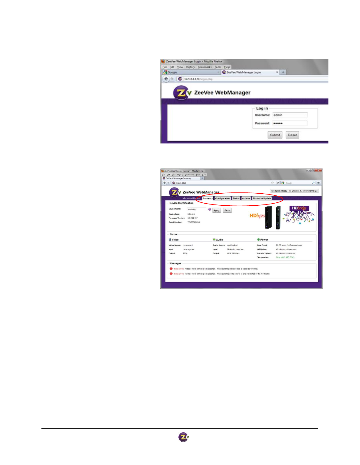
You will be directed to a login page.
The Username will always be “admin.”
The default password is “admin” but it
can be changed in the configuration tool
(see page 8).
NOTE: Login is case-sensitive.
Tabs across the top allow for different
configuration and actions.
Logging in to WebManager
Navigating in WebManager
HDbridge™ Module Configuration Manual Page 6
www.zeevee.com Rev 1.0
Page 7

The Summary tab shows general
information about the module.
1. Serial number and current channel
settings.
2. General status information.
3. Messages showing any errors or
warnings WebManager has
discovered.
The Navigation Bar on the left lists
categories that link to a specific
configuration section.
Summary Tab
Configuration Tab
HDbridge™ Module Configuration Manual Page 7
www.zeevee.com Rev 1.0
Page 8
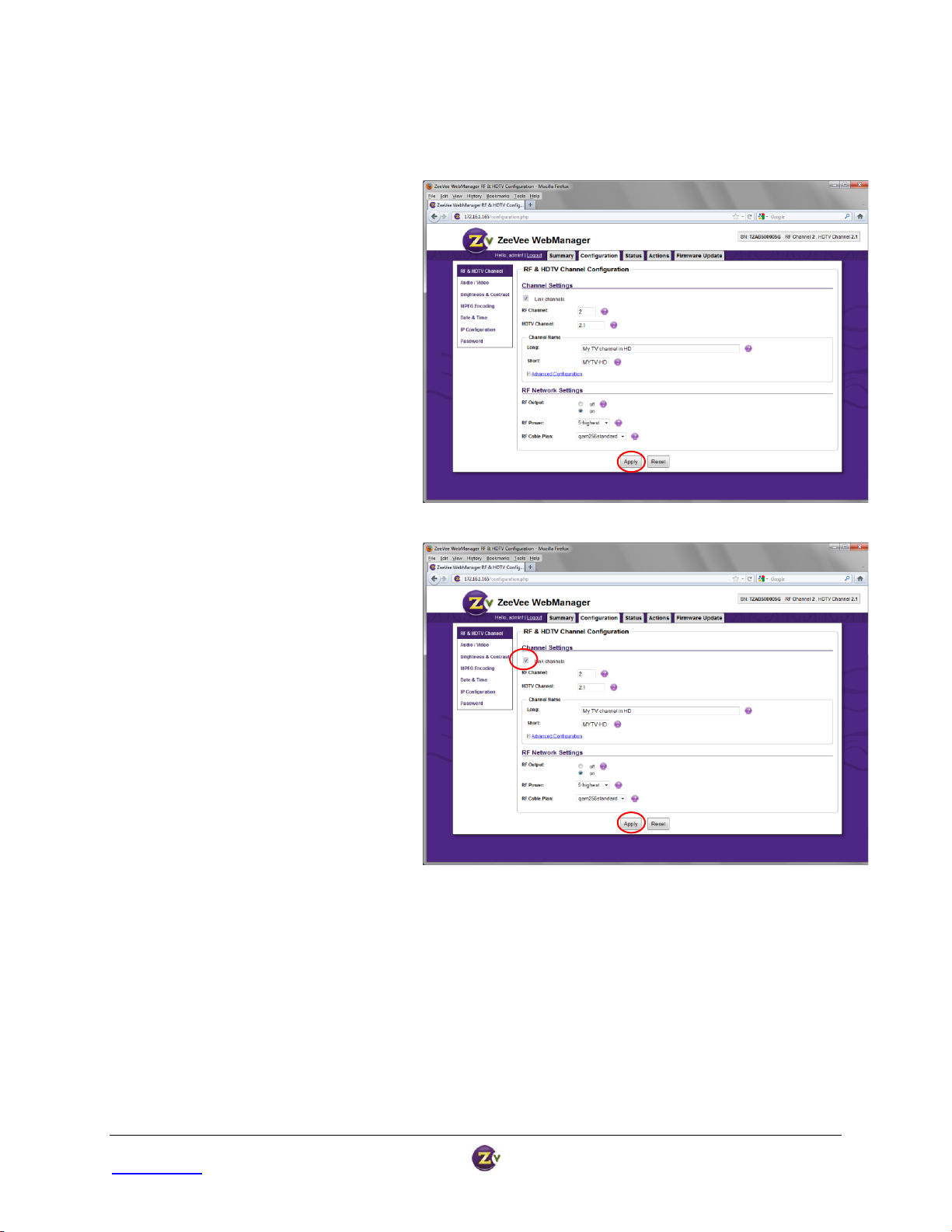
RF & HDTV Channel
To change the RF and HDTV channel:
1. Enter the RF and HDTV channel the
HDbridge module should use for
broadcast.
By default, they are linked – so if the
RF Channel is 2, the HDTV channel
will default to 2.1.
2. Long and Short channel names may
be displayed by the HDTV.
3. Hit “Apply” to save your changes.
4. After clicking “Apply,” the changes
will be displayed.
To create an HDTV (virtual) channel that’s
different from the RF channel:
1. Uncheck “Link Channels.”
2. Set RF and HDTV channels
independently.
3. Hit “Apply” to save your changes.
RF & HDTV Channel Configuration is where most changes typically occur.
HDbridge™ Module Configuration Manual Page 8
www.zeevee.com Rev 1.0
Page 9
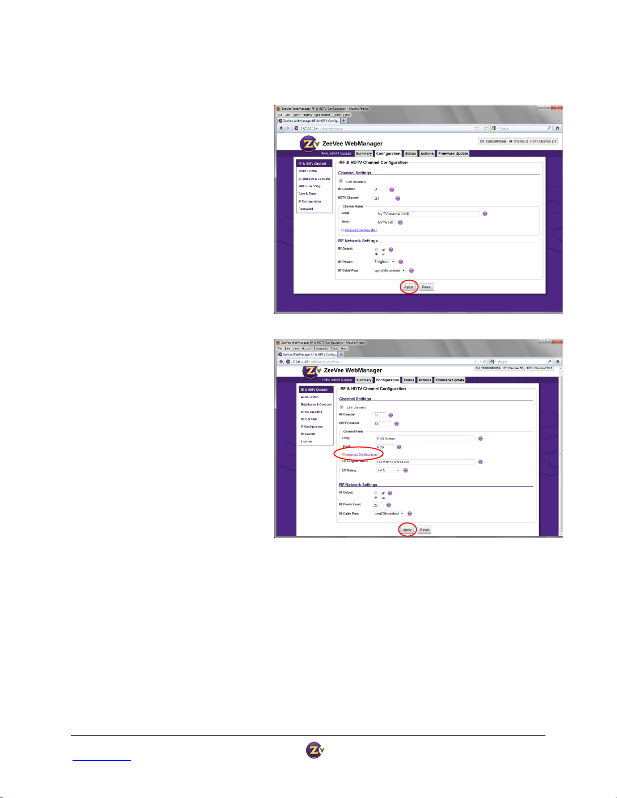
Additional changes you can make:
1. RF Output: Turns the broadcast
on and off.
2. RF Power: Defaults to highest of
25dBmV; it can be changed in
increments of 1 down to 5dBmV.
3. RF Cable Plan: Allows for changing
between QAM 256 and QAM 64, as
well as STD, HRC, and IRC.
4. Hit “Apply” to save your changes.
For advanced channel settings:
1. Click the “Advanced Configuration”
link to display Event Information
Table (EIT) options.
2. EIT Program Name: Similar to Long
and Short names, it may be displayed
on the HDTV in “Guide” or “Info.”
3. Rating: Used to apply a “rating” to
content, especially for use with tools
like V-Chip.
4. Hit “Apply” to save your changes.
RF & HDTV Channel (continued)
HDbridge™ Module Configuration Manual Page 9
www.zeevee.com Rev 1.0
Page 10
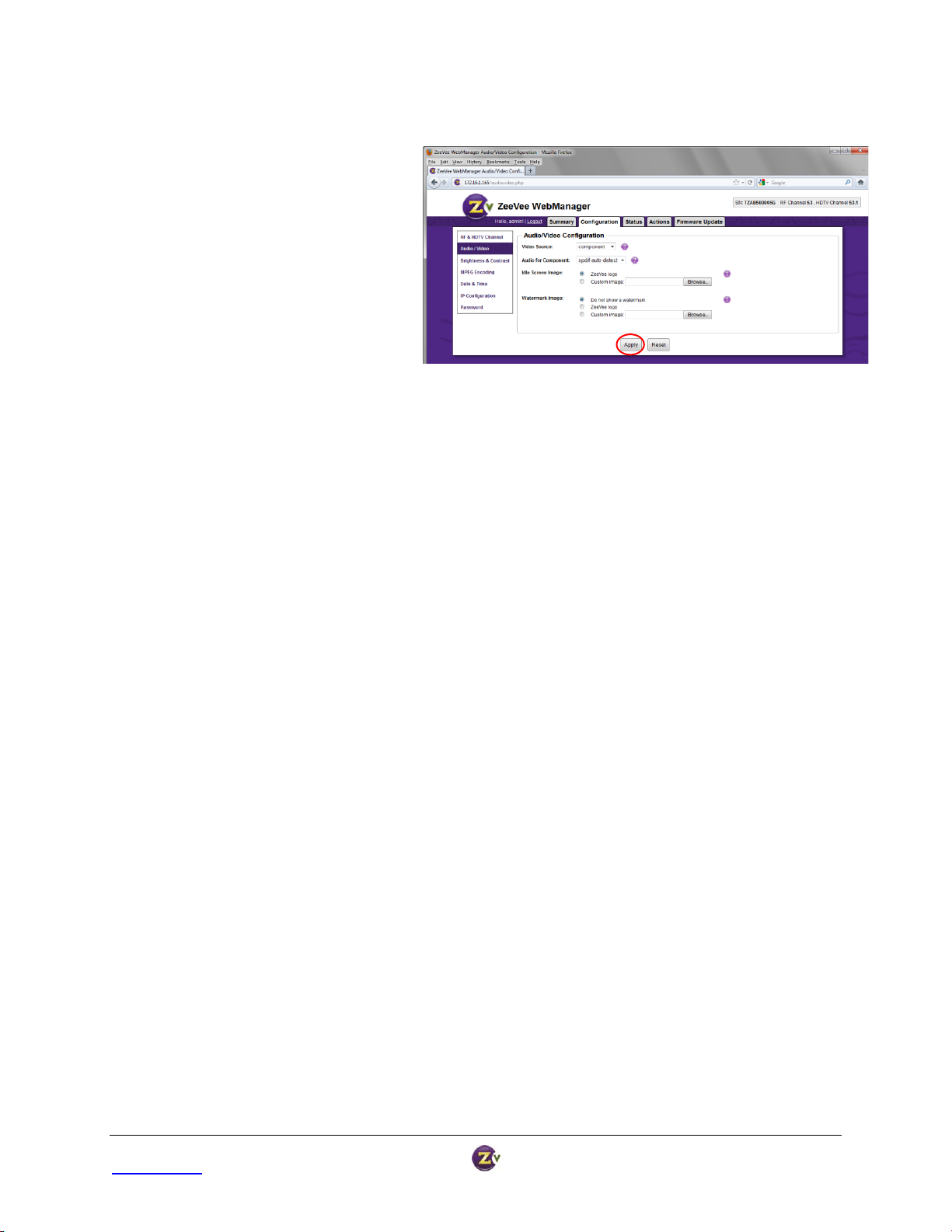
Audio / Video
1. Video Source: Defaults to Component.
Other options include Test Image or
Idle Screen.
2. Audio Source: Defaults to “auto-
detect.” It can be set to “none” or to a
specific input.
3. Idle Screen: Defaults to a bouncing
ZeeVee logo. A new image can be
uploaded to customize the idle screen
for each channel.
NOTE: Images for the custom idle
screen must have a resolution of
1280x720 or less. Images with a
resolution of 700x500 or less will
“bounce” around the TV screen;
otherwise the image will be fixed
in the center of the screen. The
image is not scaled. Accepted file
types are PNG, JPG, GIF or BMP.
4. Watermark: A “bug” that fades in and
out in the bottom right corner. By
default it is turned off. Like the idle
screen it can be customized with
another image. Accepted file types are
PNG, JPG, GIF or BMP.
NOTE: The image for a watermark
must have a resolution of 64x64 or
less.
5. Hit “Apply” to save your changes.
HDbridge™ Module Configuration Manual Page 10
www.zeevee.com Rev 1.0
Page 11

MPEG Encoding
The Output Data Rate defaults to 34.
However, some HDTVs may show break-up
with fast motion video (mostly Sharps, but
also some older LGs or Samsungs).
If so, select a lower data rate.
Hit “Apply” to save your changes.
For advanced MPEG Encoding options:
1. Click the “Advanced Configuration” link.
2. Audio and Video Delay: Set audio and
video delay independently to adjust for
lip sync issues.
3. DC Coefficient: Used in the encoding
process, this can affect picture quality
and some HDTVs’ ability to display.
4. PID and Program Number: Often needed
when using a custom cable set-top box
instead of the HDTV tuner.
5. Hit “Apply” to save your changes.
IMPORTANT NOTE: Advanced Option changes for MPEG encoding are rarely needed.
It is strongly recommended that you avoid making changes unless all other options fail.
1. IP Address Type: DHCP is set by default. IP
addresses will be assigned by the local
DHCP server.
2. Static IP Address Configuration: Static IP
addresses can be assigned. Select “Static”
in “IP Address Type” (above) and enter the
appropriate IP address, Mask, and Default
Gateway.
Important Note: Resetting to defaults
via WebManager or the reset pin on
back of the unit will also change the IP
settings back to “DHCP.” This is
important because if a static IP address
is set and you lose access because of
the settings, you can reset it by using
the pin on the back of the unit.
3. Hit “Apply” to save your changes.
IP Configuration
HDbridge™ Module Configuration Manual Page 11
www.zeevee.com Rev 1.0
Page 12
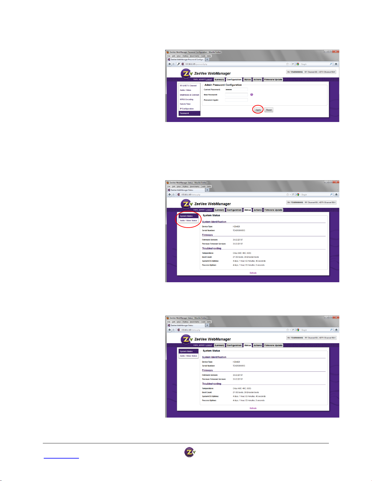
Password Management
Since the HDbridge units can be accessed
over a network, changing the password
allows for added security.
User Name is always “admin” the
passwords can be set independently for
each module.
Resetting to defaults via WebManager or
the reset pin on the back of the unit will
change the password to “admin.”
Hit “Apply” to save your changes.
The Status tab provides general information
about the module.
The Navigation Menu on the left allows you
to select between “System” and
“Audio/Video” Status.
1. Firmware: Current and previous version
of firmware.
2. Temperature: Monitored in three
different locations inside each unit.
3. System and Process Uptime: Total
uptime for both the module and the
encoder processes.
4. Refresh: Information does not update
automatically. Use the “Refresh” link to
see updates to the data.
Status Tab
System Status
HDbridge™ Module Configuration Manual Page 12
www.zeevee.com Rev 1.0
Page 13
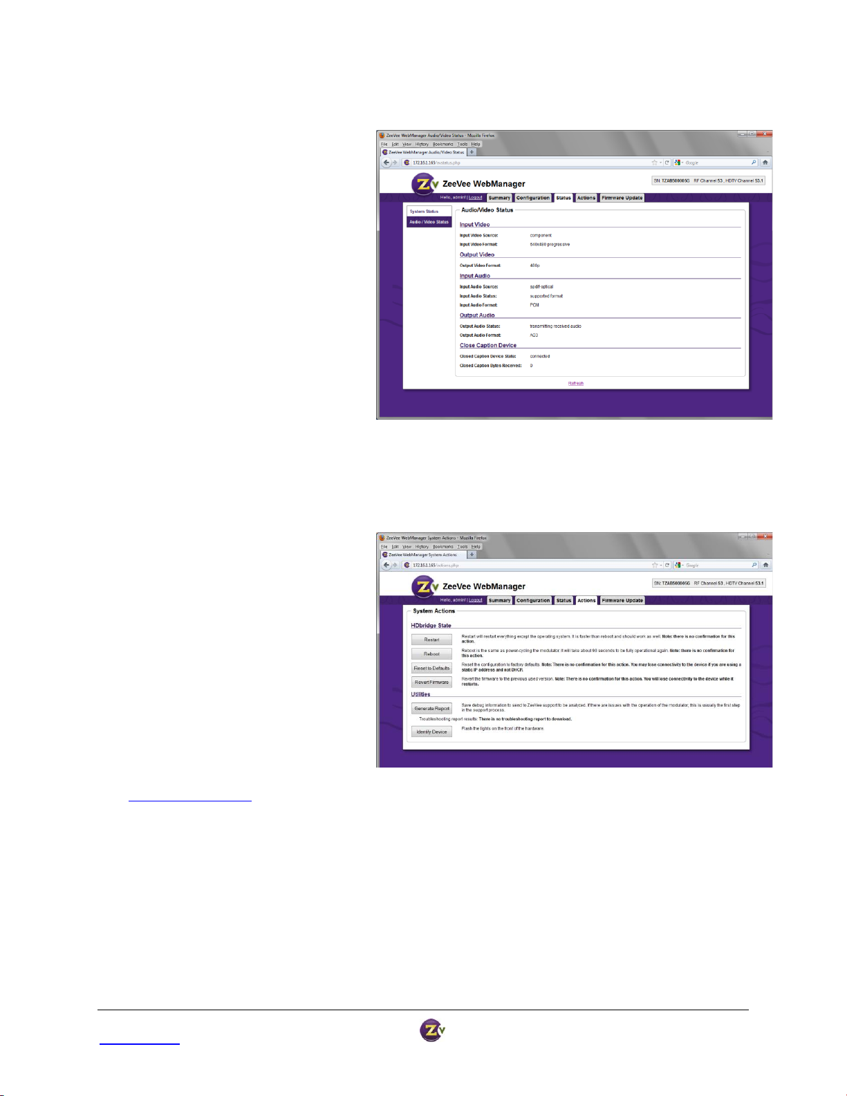
Audio/Video Status
1. Input Video: Video source and the
recognized format.
2. Output Video: Output video format will
match the input. HDBridge modules do
not scale.
3. Input Audio: Audio source, status, and
format.
4. Output Audio: Audio output source and
format.
5. Closed Caption Device: Closed Caption
will always be connected, as it is built
in, but only when it is active will the
Bytes Received show increments.
6. Refresh: Information does not update
automatically. Use the “Refresh” link to
see updates to the data.
The Actions tab allows you to restart or
reboot the module, save your changes, run
reports, etc.
1. Restart and Reboot: All configuration
settings are saved through Restart and
Reboot.
2. Reset to Defaults: Changes all
configuration settings back to factory
defaults and restarts the module.
3. Revert Firmware: Reverts the firmware
to the previously used version.
4. Generate Report: Generates a
troubleshooting report, then a link
appears to download the file and email
it to ZeeVee Tech Support
(support@zeevee.com).
5. Identify Device: Signals the module to
flash the lights on the front of the unit,
making it easy to identify a specific
module.
Actions Tab
HDbridge™ Module Configuration Manual Page 13
www.zeevee.com Rev 1.0
Page 14

Firmware Update Tab
The Firmware Update tab makes it easy
to update your firmware by walking you
through a three-step process.
1. Available Images: Click the
appropriate link to save the correct
firmware file locally.
2. Browse: Browse to the file on your
local PC.
3. Upload & Install: Firmware will
update and the module will reboot
when finished. All settings are saved
with the firmware update.
HDbridge™ Module Configuration Manual Page 14
www.zeevee.com Rev 1.0
Page 15

Troubleshooting
No Picture ... Verify the HDTV has a QAM (digital cable) tuner. Verify that you have performed a full channel scan
on the HDTV with “cable mode” selected. Verify that the modulator is not conflicting with any other channel by
connecting the HDbridge Module directly to the HDTV.
Idle Screen (bouncing logo) ... This happens because the modulator cannot detect the video source. Verify the
source is on and producing a video signal. Verify that the component cable is connected to the source and
modulator correctly. Verify that the green connector is in the green port, blue connector in the blue port, and red
connector in the red port.
Image Breakup ... You may have chosen a channel number that is not completely vacant. Some analog modulators
may spill over to adjacent channels and cause interference. Also, cable companies sometimes have extra signals
where there should be none. Try moving the module channel to another location.
You may be experiencing an RF power balance issue. Verify that the RF power of the modulator is balanced with
signals from other modulators and from the cable company.
Your HDTV may not be able to play the high data rate that the HDbridge module produces during fast action.
Lower the data rate via the web interface.
1080 or 720 video input is not supported on this product ... This message is displayed on the screen when the video
source resolution exceeds the capability of your HDbridge module. Set the video source to the appropriate
resolution.
No Audio ... Verify that digital audio is connected to the modulator and to the source. Verify that the source audio
output is set to PCM or AC-3.
Contact ZeeVee
For support, repairs, and warranty service ................................... 877-4ZEEVEE (877-493-3833)
For purchasing and sales inquiries ............................................... 978-633-ZVHD (978-633-9843)
Warranty
Limited One Year Warranty: ZeeVee warrants your HDbridge Module against defects in materials and workmanship for
a period of one year from the date of purchase. Visit www.zeevee.com for complete warranty details.
To Get Warranty Service: Warranty service will be provided by ZeeVee. If you believe you need service for your
product, please contact ZeeVee directly by calling ZeeVee Support at (877) 493-3833. If it is determined that the
product needs to be returned for service or exchange, you will receive a Return Material Authorization (“RMA”)
number. Our agents will help you through the process through which you can return the product. ZeeVee is not
responsible for Customer products received without an RMA number and may reject such products.
To Get Out-Of-Warranty Service: To obtain out-of-warranty service for your product please call ZeeVee Support at
(877) 493-3833 for information on the possibility of and any costs for repair or replacement of out-of-warranty
products. No agent, company, dealer, distributor, or person is authorized to change, modify, or extend the terms of
these warranties in any manner.
HDbridge™ Module Configuration Manual Page 15
www.zeevee.com Rev 1.0
 Loading...