

Page 1
HDbridge3000
CONFIGURATION GUIDE
NA
Page 2

Page 2 | HDbridge3000 Configuration Guide www.zeevee.com
Important Safety Instructions. Save These Instructions.
WARNING: When using electronic products, basic precautions should always be followed, including:
1. Keep these instructions.
2. Heed all warnings.
3. Follow all instructions.
4. Do not use this apparatus near water.
5. Clean only with dry cloth.
6. Do not block any ventilation openings. Install in accordance with the
manufacturer’s instructions.
7. Do not install near any heat sources such as radiators, heat registers,
stoves, or other apparatus (including
ampliers) that produce heat.
8. Do not defeat the safety purpose of the polarized or grounding-type
plug. A polarized plug has two blades with one wider than the other.
A grounding type plug has two blades and a third grounding prong.
The wide blade or the third prong is provided for your safety. If the
provided plug does not t into your outlet, consult an electrician for
replacement of the obsolete outlet.
9. Power cord must be accessible to allow for the removal of power from
the unit.
10. Protect the power cord from being walked on or pinched, particularly
at plugs, convenience receptacles, and the point where they exit from
the apparatus.
11. Unplug the apparatus during lightning storms or when unused for long
periods of time.
12. Only use attachments/accessories specied by the manufacturer.
13. Refer all servicing to qualied service personnel. Servicing is required
when the apparatus has been damaged in any way, such as powersupply cord or plug is damaged, liquid has been spilled or objects
have fallen into the apparatus, the apparatus has been exposed to rain
or moisture, does not operate normally, or has been dropped.
14. WARNING: To reduce the risk of re or electric shock do not place this
apparatus in a position where it is exposed to dripping or splashing
liquids, rain, moisture, or excessively high humidity. Objects containing
liquid shall not be placed in proximity to the unit such that they
present a risk of spillage onto the apparatus.
The lightning ash with arrowhead symbol, within an
equilateral triangle, is intended to alert the user to the
presence of uninsulated “dangerous voltage” within the product’s enclosure that may be of sufcient
magnitude to constitute a risk to persons.
The exclamation point within an equilateral triangle is
intended to alert the user to the presence of important
operating and maintenance (servicing) instructions in
the literature accompanying the product.
CAUTION: TO REDUCE THE RISK OF ELECTRIC SHOCK
DO NOT REMOVE THE COVER (OR BACK).
NO USER SERVICABLE PARTS INSIDE.
REFER SERVICING TO QUALIFIED SERVICE PERSONNEL.
FCC Statement
FCC Compliance and Advisory Statement: This hardware device complies with Part 15 of the FCC rules.
Operation is subject to the following two conditions: 1) this device may not cause harmful interference, and 2) this device must accept any interference received including interference that may cause
undesired operation. This equipment has been tested and found to comply with the limits for a Class
A digital device, pursuant to Part 15 of the FCC Rules. These limits are designed to provide reasonable
protection against harmful interference in a commercial installation. This equipment generates, uses,
and can radiate radio frequency energy and, if not installed or used in accordance with the instructions,
may cause harmful interference to radio communications. However there is no guarantee that interference will not occur in a particular installation. If this equipment does cause harmful interference to
radio or television reception, which can be determined by turning the equipment off and on, the user is
encouraged to try to correct the interference by one or more of the following measures: 1) reorient or
relocate the receiving antenna; 2) increase the separation between the equipment and the receiver; 3)
connect the equipment to an outlet on a circuit different from that to which the receiver is connected;
4) consult the dealer or an experienced radio/TV technician for help. Any changes or modications not
expressly approved by the party responsible for compliance could void the user’s authority to operate
the equipment. Where shielded interface cables have been provided with the product or specied additional components or accessories elsewhere dened to be used with the installation of the product,
they must be used in order to ensure compliance with FCC regulations.
INSTRUCTIONS PERTAINING TO A RISK OF FIRE, ELECTRIC SHOCK, OR INJURY TO PERSONS
Page 3
HDbridge3000 Configuration Guide | Page 3
ZeeVee products convert your video and audio source
to a digital cable channel and broadcast it over RF and
IP networks* to all your HDTVs. This guide walks you
through basic and more enhanced setup for ZeeVee’s
HDbridge3000 modulator.
If you run into problems during setup, feel free to contact
Technical Support at +1(877) 4-ZEEVEE (1.877.493.3833).
Table of Contents
Panel Layout ................ 4-5
Basic Installation ...............6
Beginning setup ..............6
Tuning your channel at
the HDTV (Auto Scan) ..........6
Status Display ................7
Maestro Conguration ....... 8-11
Connecting with Maestro .......8
Conguring RF numbers
and virtual channels ...........8
Map for conguring RF channels
and virtual channels ...........9
Using Auto Increment .........10
Using other Maestro tabs ......11
Troubleshooting ..............14
Warranty ....................15
Contact ZeeVee ...............16
What’s in the Box
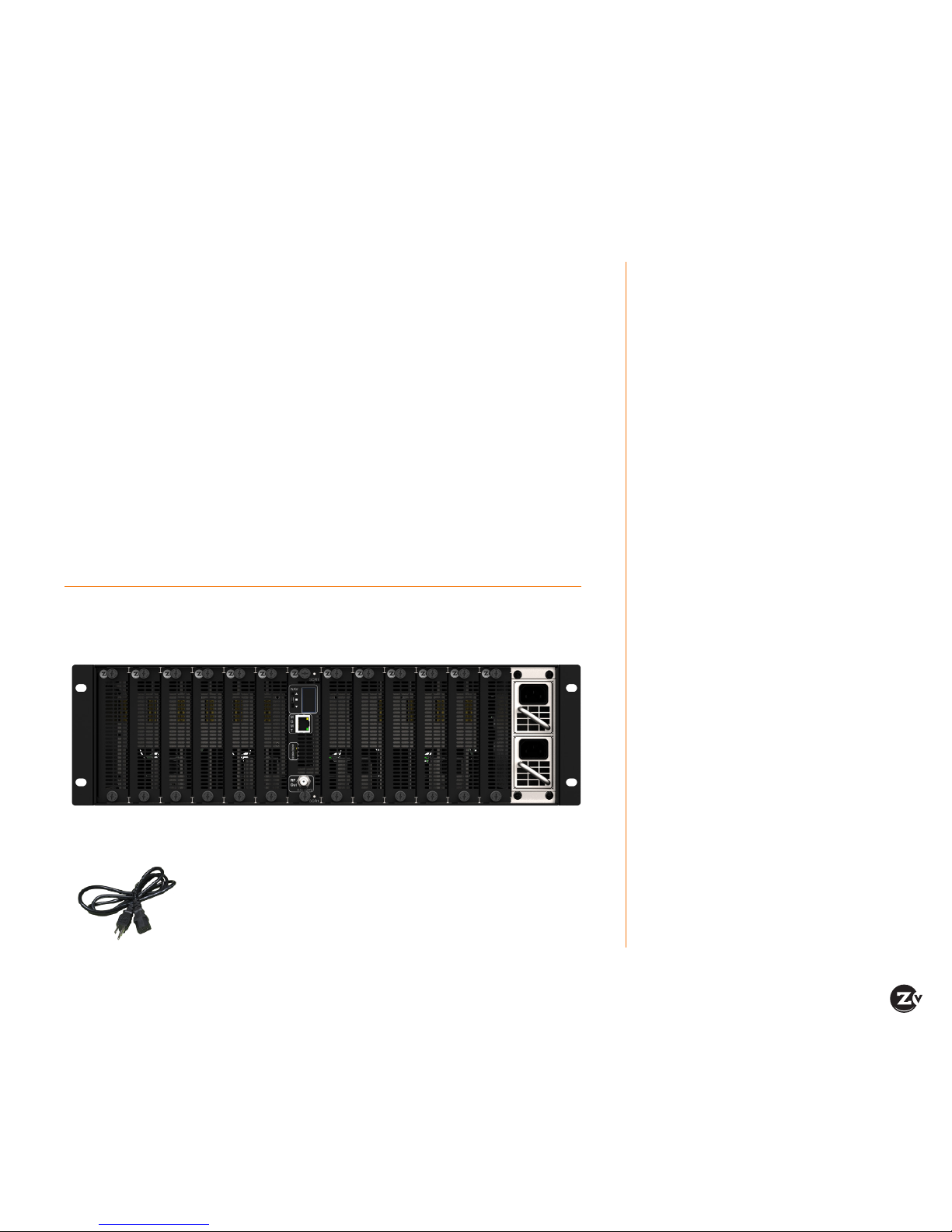
Here’s what you can expect to nd when you open the package:
2 x Power Cords
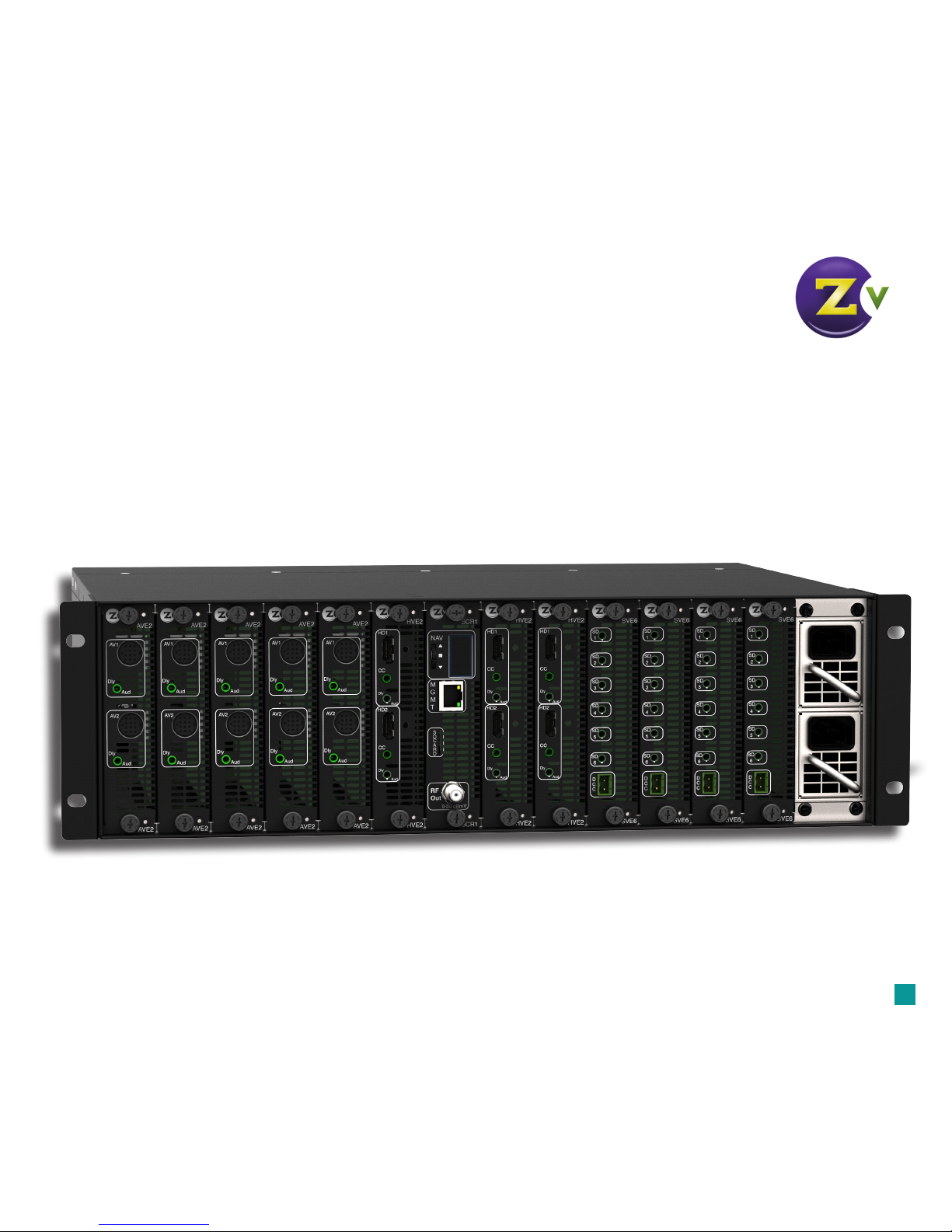
1 x ZeeVee HDbridge3000 Chassis with Control Module and 2x hot-swappable power
supplies. Media Modules are sold separately.
Welcome to ZeeVee.
*Not all cards support RF and IP.
Page 4
Page 4 | HDbridge3000 Configuration Guide www.zeevee.com
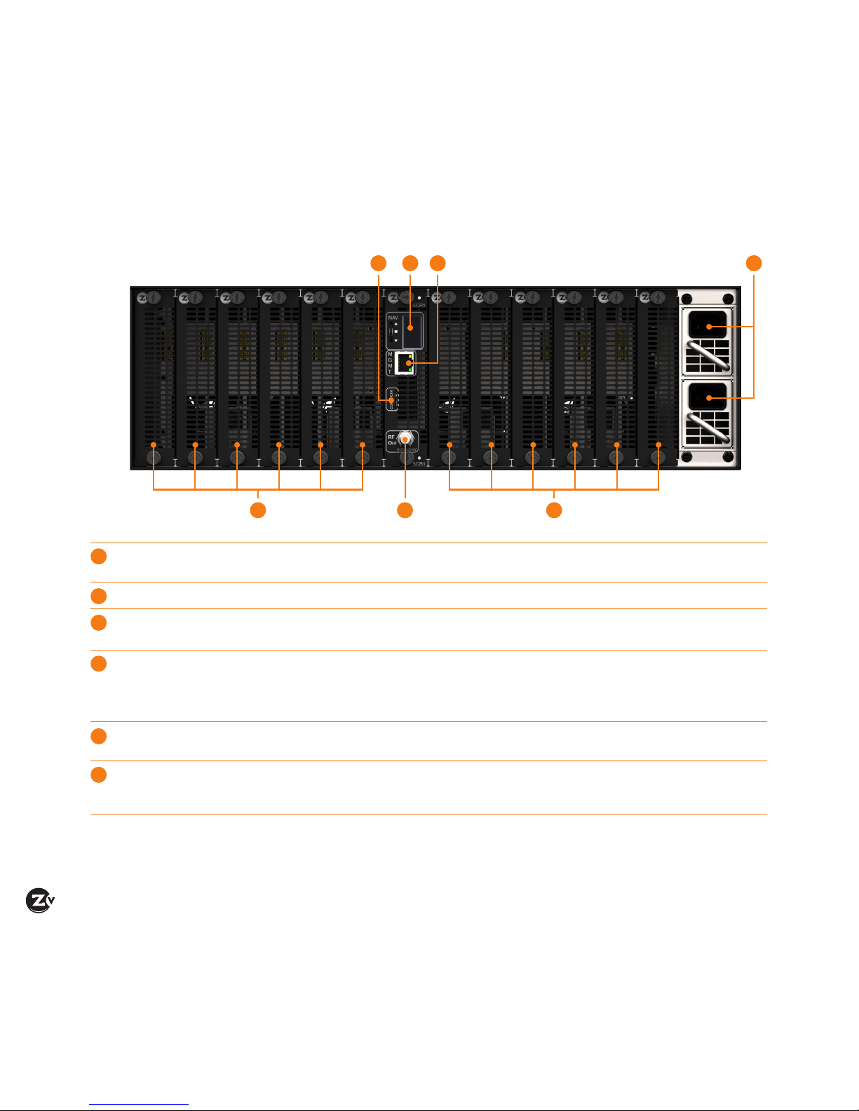
Panel Layout
Card Slots Slots are identied as 1 through 12, from left to right. Any combination of
cards can be installed using the HDbridge3000.
SD Card This slot is reserved for future use.
Status Display Displays conguration and system status. This display can also be found
on the opposite panel. See page 7 for details.
RF Out Depending upon which cards are installed, the HDbridge3000 can transmit
up to 24 channels of HD content or 72 channels of SD content. Output
power can be set between +34 and +13 dBmV using the Maestro web
interface. The default output power setting is +34 dBmV.
MGMT and IP Out Ethernet port provides access to the Maestro web interface and
distribution of video over IP networks.*
Power Supplies 100 - 240 V AC / 50 - 60 Hz, hot-swappable, dual-redundant power supplies.
Both AC power cords (included) must be connected to the HDbridge3000
for proper operation.
4
5 632
1
1
2
3
4
5
6
1
* Not all cards support IP out.
Page 5
HDbridge3000 Configuration Guide | Page 5
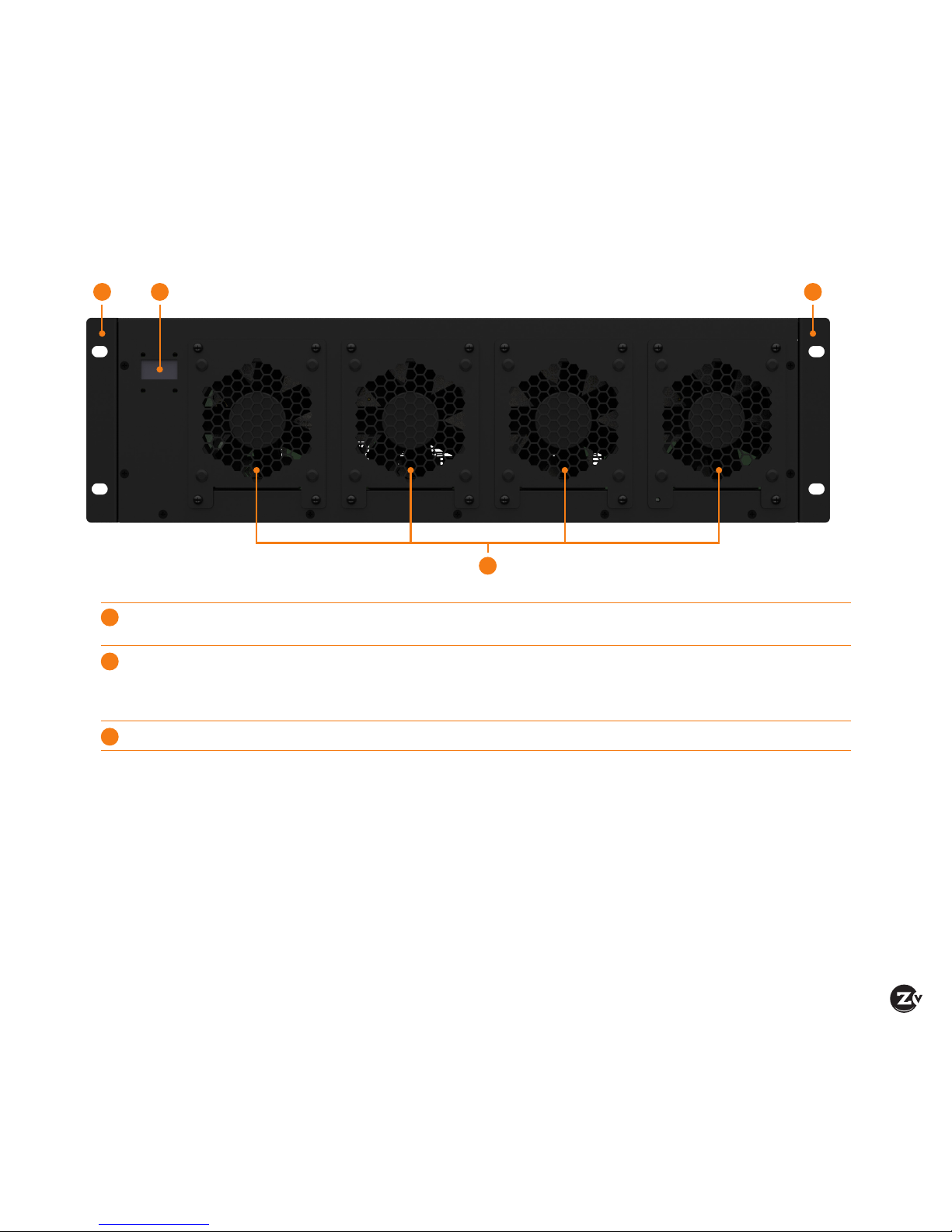
Display Displays conguration and system status. This display can also be found
on the opposite panel.
Cooling Fans Hot-swappable, high-capacity cooling fans. Air is pulled in from these fans
and expelled through the front panel. When installing the HDbridge3000,
make sure that these fans are not blocked and clear from other heatgenerating sources.
Rack Ears Front or rear-mountable rack ears allow for exible mounting options.
13 3
2
1
2
3
Page 6

Page 6 | HDbridge3000 Configuration Guide www.zeevee.com
Basic Installation
Optional Delay Matched
Analog Audio Out to
audio system
per card
Component and/or VGA cable
per card
Coax cable connects to
coax network
Power cords
to available
AC outlets
Ethernet cable
connects to LAN
CC
Dly Dly
Component
Video Out
Digital
Audio
CCAnalog
Audio Out
x 2 x 2
per card
Composite
Video Out
x 6
NOTE: Illustration shows HDbridge3000 with HDMI, Component/VGA, and Composite cards, which are sold separately.
Before operating the HDbridge3000, it is recommended to
update to the latest version of rmware, which can be found
on the Support section of the ZeeVee website.
Beginning Setup
1. Install the desired module in each slot. Screws should
be hand-tightened. Do not use pliers or other high-torque
devices.
2. Connect each source device to each card using
the required cables. See the illustration, above, for
information.
3. Connect an Ethernet cable from the MGMT port to the IP
network or directly to the PC.
4. Connect a coaxial cable from the RF Out port to the RF
network.
5. Connect the included AC power cords from both power
supplies to available AC outlets.
Tuning your channel at the HDTV (Auto Scan)
1. Select the Cable setting (not Air or Antenna) in your TV
menu.
2. Enter the RF number to tune directly to the channel.
If you cannot tune directly to the channel at this point, it is
because most TVs will require you to run a full Auto Scan.
(Requires ZeeVee CAVC6 3.5mm plug to RCA
Composite AV cable)
(Requires ZeeVee CAVC6 3.5mm plug to RCA
Composite AV cable)
NOTE: Defaults are RF # 2 through 25 with matching channel
numbers (e.g. 2/2/1, 3/3.1, etc). Composite cards use three
sub-channels per RF # (e.g. 2 / 2.1, 2.2, 2.3).
Page 7

HDbridge3000 Configuration Guide | Page 7
Status Display
The HDbridge3000 has a small display, located on both the front and back panel of the unit. When the display is in "standby",
the ZeeVee logo is displayed. Press the NAV wheel to display the IP address / port status of the HDbridge3000. To change
the IP address of the HDbridge3000, use the Network tab in the Maestro web interface.
If the ZeeVee logo
is displayed, press
the control wheel
to display the IP
address of the unit:
Press and release the NAV wheel to
display the IP address of the HDbridge3000. The display will return
to the ZeeVee logo after about 10
Page 8

Page 8 | HDbridge3000 Configuration Guide www.zeevee.com
Conguring RF and channel numbers
1. Click on the RF Channel Plan tab.
2. Congure the RF # and Channel # elds.
3. Click in the RF # eld and enter the RF number. RF
channels must be within 400 MHz of one another. Refer
to the map, on the next page, for more information.
4. Click in the Channel # eld and enter a channel number
(virtual channel). The channel number is what the TV
displays. You can congure a channel number two ways:
• As a dotted number — Enter the number with a “.”
following it, for example, “5.1”. This is the default
display.
• As a dotless number — Enter the number with a “#”
preceding it, for example, “#5”. Note that you can
choose a channel number that is different from the
RF#. For instance, if your RF# is 3, you can choose a
channel number of 10.1 or #10.
5. Click Apply to save changes. Your unit stores
congurations so they are not lost on power-down.
6. Run Auto Scan at TV (see Tuning your channel at the
HDTV, page 5) when you have saved conguration
changes.
Maestro is a conguration tool that is used to control all
features on the HDbridge3000.
Connecting with Maestro
1. Connect the HDbridge3000 to a LAN with a DHCP server
or directly to a PC using a standard Ethernet cable. Do
not use a crossover cable.
2. After a few moments, an IP address will appear at the top
of the display.
3. Using any web browser
(Chrome or Firefox preferred),
enter the IP address to launch
Maestro. Internet Explorer is
not supported but Microsoft
Edge is.
4. The Log In dialog will be
displayed. The default
password is admin.
Login is case-sensitive.
To change the password,
use the Device tab.
5. After the password is accepted, the Status tab is
displayed.
IP address
Maestro Conguration
Page 9

HDbridge3000 Configuration Guide | Page 9
Map for conguring RF
channels and virtual channels
The table, to the right, shows how
logical RF channels are matched with
RF frequencies. Refer to this map
when conguring RF channels.
The highlighted areas, in the map,
indicate RF channels which are not
sequential.
NOTE: When entering RF channels,
they must be within 400 MHz of each
other.
To illustrate, Example 1 shows two RF
channels which are sequential and are
within 400 MHz of one another.
In Example 2, although the RF channels
are sequential, the difference between
the two RF frequencies exceeds 400
MHz. When a channel is beyond this
range, no output will be displayed.
In this example, channel 100 will be
"muted".
Cable TV Channels vs RF Frequency (MHz) Map
RF Ch. Band (MHz) RF Ch. Band (MHz) RF Ch. Band (MHz) RF Ch. Band (MHz) RF Ch. Band (MHz)
2 54-60 27 240-246 57 420-426 87 600-606 122 780-786
3 60-66 28 256-252 58 426-432 88 606-612 123 786-792
4 66-72 29 252-258 59 432-438 89 612-618 124 792-798
5 76-82 30 258-264 60 438-444 90 618-624 125 798-804
6 82-88 31 264-270 61 444-450 91 624-630 126 804-810
95 90-96 32 270-276 62 450-456 92 630-636 127 810-816
96 96-102 33 276-282 63 456-462 93 636-642 128 816-822
97 102-108 34 282-288 64 462-468 94 642-648 129 822-828
98 108-114 35 288-294 65 468-474 100 648-654 130 828-834
99 114-120 36 294-300 66 474-480 101 654-660 131 834-840
14 120-126 37 300-306 67 480-486 102 660-666 132 840-846
15 126-132 38 306-312 68 486-492 103 666-672 133 846-852
16 132-138 39 312-318 69 492-498 104 672-678 134 852-858
17 138-144 40 318-324 70 498-504 105 678-684 135 858-864
18 144-150 41 324-330 71 504-510 106 684-690
HRC Frequencies =
Standard
Frequencies
minus 1.25 MHz
Except for:
Channel 5,
Video = 78.0 MHz
Channel 6,
Video = 84.0 MHz
IRC Frequencies =
Standard
Frequencies
Except for:
Channel 5, Video =
79.25 MHz
Channel 6, Video =
85.25 MHz
19 150-156 42 330-336 72 510-516 107 690-696
20 156-162 43 336-342 73 516-522 108 696-702
21 162-168 44 342-348 74 522-528 109 702-708
22 168-174 45 348-354 75 528-534 110 708-714
7 174-180 46 354-360 76 534-540 111 714-720
8 180-186 47 360-366 77 540-546 112 720-726
9 186-192 48 366-372 78 546-552 113 726-732
10 192-198 49 372-378 79 552-558 114 732-738
11 198-204 50 378-384 80 558-564 115 738-744
12 204-210 51 384-390 81 564-570 116 744-750
13 210-216 52 390-396 82 570-576 117 750-756
23 216-222 53 396-402 83 576-582 118 756-762
24 222-228 54 402-408 84 582-588 119 762-768
25 228-234 55 408-414 85 588-594 120 768-774
26 234-240 56 414-420 86 594-600 121 774-780
RF Ch Band (Mhz) Difference
22 168 - 174
23 216 - 222 ~48 MHz
Example 1
RF Ch Band Difference
99 114 - 120
100 648 - 654 ~534 MHz
Example 2
Page 10

Page 10 | HDbridge3000 Configuration Guide www.zeevee.com
Using Auto Increment
When several cards are installed, manually entering the RF
# and Channel # can become a lengthy process. To aid in
this process, use the Auto Increment feature to automatically
populate the desired elds.
1. Make sure all cards, that will be affected by the Auto
Increment feature, are selected. Select a card by
checking the box next to the card, under the Slot column.
If the card is "grayed-out" then the Auto Increment feature
will not affect that card.
2. Click the RF # drop-down list and select Auto
Increment.
3. In the Auto-Increment dialog, enter the desired RF channel
in the First channel eld.
4. Click the Channel check box and enter the desired channel
in the First channel eld.
In this example, values 3 and 3.1 have been entered.
The value 3.1 may also be entered as #3.
5. Click the Set button to save the changes.
6. The Auto Increment dialog will indicate that the values
have been set.
7. Click the Close button.
8. The RF # and Channel # columns are now automatically
incremented, as shown.
9. Click the Apply button.
10. Maestro will apply the changes to each device. Once
all changes have been successfully applied, the Save
Conguration dialog will be displayed.
11. Click the Close button to dismiss the dialog.
NOTE: All saved settings are retained, even if the
HDbridge3000 is powered-off. Card settings are automatically
migrated when swapping cards of the same type.
check box
Page 11

HDbridge3000 Configuration Guide | Page 11
Using other Maestro tabs
Click on any other Maestro tab to congure your unit as needed. We provide brief information below. Please click on the Help
button on each tab or refer to the Support section of our website for further detail on conguration options.
AV Source tab
Allows for specifying audio
and video inputs and adjusting
settings such as Delayed
Audio Out (for matching audio
to external audio systems).
RF tab
Allows you to change the
RF power output. You can
also change from QAM256
to QAM64 and from QAM
Standard to HRC or IRC.
Device tab
Allows you to change the
device password and update
rmware as well as congure
Emergency Alerts System
(EAS). For more information,
refer to the EAS application
note in the Support section
on our website.
Group Action bar allows you to set
conguration for all selected units
actively managed on your network.
Page 12

Page 12 | HDbridge3000 Configuration Guide www.zeevee.com
Network tab
Allows you to congure IP
settings. By default the
HDbridge3000 uses DHCP
to obtain an IP address for
the control module. To use
an STB or EAS, an IP address
must be assigned to each
media module (card) using the
Static or DHCP setting.
ZvShow tab
ZvShow allows for adding an
extra channel, using a video
le, to your broadcast line up.
This channel is disabled by
default, but can be enabled at
any time under the RF Channel
Plan tab. Visit zeevee.com/
zvshow for details.
STB tab
Provides management of
DirecTV H25 receivers. For
more information, refer to
the ZvSTB application note
in the Support section on our
website.
Page 13

HDbridge3000 Configuration Guide | Page 13
Admin tab
Use this Admin tab to create
user accounts and grant
access to specic functions
within the Maestro web
interface. Maestro allows for
a total of 10 custom user
accounts, not including the
"admin" account.
Support tab
Provides technical support
contact information and
allows you to send logs for
troubleshooting.
Page 14

Page 14 | HDbridge3000 Configuration Guide www.zeevee.com
Unable to
Connect
to Maestro
If unable to connect, try one of the following:
If you are getting a page not found error when directly connected to a PC, try disabling WiFi. If that does not
correct it, make sure your PC is not using a static IP address. The PC and the HDbridge3000 unit must be on the
same IP subnet for them to communicate. For details on how to check for a static IP address, please see the FAQ
section of our website.
If the page loads, but all you see is a purple background and the ZeeVee logo (and are not prompted to log
in) please try a different web browser. Please use use a supported browser such as Mozilla Firefox, Google Chrome,
or Microsoft Edge. Microsoft Internet Explorer is not supported.
No picture or
channel found
at TV
Verify the HDTV has a QAM (digital cable) tuner. Verify that you have performed a full channel scan on the HDTV with
“cable mode” selected. Lower the power on the unit, then verify that the modulator is not conicting with any other
channel by connecting the unit directly to the HDTV.
Idle Screen
(bouncing logo)
One reason this may happen is when the unit does not detect video input. Verify the source is on and producing a
video signal, then verify the source is outputting a supported resolution.
Image Breakup
Image or video break up is often caused by an issue in the RF/coax network. You may have chosen a channel number
that is not completely vacant.
If you are combining with other modulators, be sure the RF# selected on the unit does not conict with any other
channels, keep in mind that some analog modulators may spill over to adjacent channels and cause unexpected
interference.
If you are combining with a cable service, keep in mind that they sometimes have extra signals that a TV will not
display and can cause interference.
There may also be an RF power balance issue. Verify that the RF power of the unit is balanced with signals from
other modulators and from the cable company. As a test, try removing all other signals (cable, other modulators, etc)
and see if you still see similar issues.
Some TVs will also show video issues if the signal strength is too high. Try lowering the RF power on the unit to
ensure you are not overdriving the HDTV tuner.
Audio and
video are not
synchronized
If both the audio and video are being sent through the unit to the TV, be sure your rmware is fully updated, later
versions of rmware may have lip sync corrections.
If you are feeding the audio directly from the source into a distributed (whole house) audio system and not through
the ZeeVee unit, it will arrive to the speakers before the video arrives to the HDTV. This happens because the video
is being encoded into a digital signal, modulated by the unit and then demodulated at the HDTV. Each of these steps
adds latency that will not be reected in the audio because it is traveling a shorter path.
To work around the issue, you can try one of the following:
Use an audio delay device that allows you to add a delay to the audio stream before it reaches the sound system.
Use the Dly Aud port on the card, if available, and adjust the delay amount using Maestro.
Feed the audio to the ZeeVee unit and send it to the HDTV with the video. Then take the audio out from an HDTV
or external QAM tuner (such as the ZvSync) and connect it to your audio system. The audio should have a similar
amount of delay since it has gone through the encoding and decoding process just as the video did.
Troubleshooting
Page 15

HDbridge3000 Configuration Guide | Page 15
WARRANTY
HDbridge3000
and ZvPro Product Lines
ZeeVee, Inc. January 1, 2014
LIMITED FIVE YEAR WARRANTY
ZeeVee warrants your ZeeVee Equipment (dened
to include only HDbridge Series and ZvPro Series
of equipment) against defects in materials and
workmanship for a period of ve years from the date
of purchase. ZeeVee’s limited warranty extends only
to the original end user purchaser or any person
receiving the ZeeVee Equipment as a gift from the
original end user purchaser and to no other purchaser
or transferee. All warranties implied by law, including
any implied warranties of merchantability and tness
for a particular purpose, are expressly limited to
the duration of this express limited warranty. Some
countries or states of the U.S. do not allow limitations
on how long an implied warranty lasts, so the above
limitation may not apply to you.
EXCLUSIVE REMEDY FOR ZEEVEE EQUIPMENT
At the option of ZeeVee, the ZeeVee Equipment
will be repaired or replaced with a new, repaired or
refurbished product (whichever ZeeVee deems as
necessary) if it becomes defective or inoperative.
If ZeeVee cannot reasonably repair or replace the
ZeeVee Equipment then ZeeVee may, at its sole
discretion, refund the original purchase price or
the current retail price of the ZeeVee Equipment.
If ZeeVee chooses to repair or replace the ZeeVee
Equipment, or to refund the purchase price, this will
be the exclusive remedy. With the exception of any
warranties implied by the law of any country or state
of the U.S., this express limited warranty is exclusive
and in lieu of all other warranties, guarantees,
agreements and similar obligations of ZeeVee.
THE ABOVE WARRANTIES ARE SUBJECT TO THE
FOLLOWING CONDITIONS
• You must have proof of purchase from an
authorized ZeeVee dealer to receive warranty
service. A sales receipt or other document
showing that you purchased the ZeeVee
Equipment is considered proof of purchase.
• Warranty coverage begins the day the original end
user purchaser or any person receiving the ZeeVee
Equipment as a gift from the original end user
purchaser purchased the ZeeVee Equipment.
• All ZeeVee Equipment, including replacement
products, are covered only for the original
warranty period. When the warranty on the original
product expires, the warranty on the replacement
product also expires.
• If we determine that the problem is not covered
under the limited warranty, we will notify you and
inform you of service or replacement alternatives
that are available to you on a fee basis.
• In the case of a paid repair: at the option of
ZeeVee, the ZeeVee Equipment will be repaired
or replaced with a new, repaired, refurbished, or
comparable product (whichever ZeeVee deems as
necessary).
• ZeeVee Equipment must be purchased through an
authorized ZeeVee distribution partner and dealer/
reseller. Check zeevee.com for a list of authorized
distributors and a list of any expressly excluded
dealer/resellers. ZeeVee does not warrant
equipment purchased through grey market
resellers or certain internet resellers.
WHAT THESE WARRANTIES EXCLUDE
Your warranties do NOT cover:
•Labor charges for installation or set-up of the
ZeeVee Equipment.
• Repairs or replacement due to misuse, accident,
lightning damage, unauthorized repair, power
surges, or other causes not within the control of
ZeeVee.
• Any modications or other changes to the ZeeVee
Equipment, including but not limited to software
or hardware modication in any way other than
as expressly authorized by ZeeVee, will void these
limited warranties. Except in the case of hardware
or software provided by ZeeVee, installing
modications, “hacks,” or utilizing service access
or “back doors” will void these limited warranties.
• Reception or transmission problems caused by
signal conditions, Internet connection problems,
or any other communication systems outside the
unit.
•Expendable accessories included in ZeeVee
Equipment such as batteries.
• Any ZeeVee Equipment that has been modied
or adapted to enable it to operate in any country
other than the country for which it was designed,
manufactured, approved, and/or authorized.
• Any ZeeVee Equipment that has altered or missing
serial numbers.
• Any ZeeVee Equipment that has been opened or
otherwise tampered with.
• Problems that are directly caused as a result
of using any third party accessories, parts or
components.
• Shipping, tax or duty charges for return or
replacement of unit.
MATERIALS REQUIRED FOR WARRANTY
Please keep your sales receipt and any other
documentation showing proof of purchase. Also,
keep the original box and packaging material in case
you need to return your ZeeVee Equipment.
TO GET WARRANTY SERVICE
Warranty service will be provided by ZeeVee. If
you believe you need service for your ZeeVee
Equipment, please contact ZeeVee by calling our
customer care center at (877)-4ZeeVee; (877)-493-
3833. If it is determined that the product needs to
be returned for service or exchange, you will receive
a Return Material Authorization (RMA) number. Our
agents will help you through the process through
which you can return the product. ZeeVee is not
responsible for customer products received without
an RMA number and may reject such products.
TO GET OUT-OF-WARRANTY SERVICE
To obtain out-of-warranty service for your ZeeVee
Equipment, please contact ZeeVee by calling our
customer care center at (877)-4ZeeVee; (877)-493-
3833 for information on the possibility of and any
costs for repair or replacement of out-of-warranty
products. No agent, company, dealer, distributor, or
person is authorized to change, modify, or extend
the terms of these warranties in any manner.
LIMITATION OF LIABILITY
In no event will ZeeVee be liable for any amount
greater than the retail price of the ZeeVee
Equipment. ZeeVee shall not be liable for any
incidental or consequential damages (including
lost prots) for breach of any express or implied
warranty on the ZeeVee Equipment. Some countries
and states of the U.S. do not allow the exclusion or
limitation of incidental or consequential damages,
so the above limitation or exclusion may not apply
to you. This warranty gives you specic legal rights
and you may also have other rights, which vary from
country to country and state to state.
Page 16

NA
Contact ZeeVee
Support
For additional questions call
+1(877) 4-ZEEVEE (1.877.493.3833)
or e-mail support@zeevee.com.
Representatives are available from 9:00 AM to 6:00 PM, Monday through Friday (Eastern Time).
Sales
North America:
+1 (347) 851-7364 Phone
sales@zeevee.com
EMEA:
+44 1494 956677 Phone
EMEAsales@zeevee.com
HDbridge3000 Rev.A 2016-08
Proudly designed and built in the USA
Page 16 | HDbridge3000 Configuration Guide
 Loading...