

ZeeVee HDb2540, HDb2520 Quick Start Manual
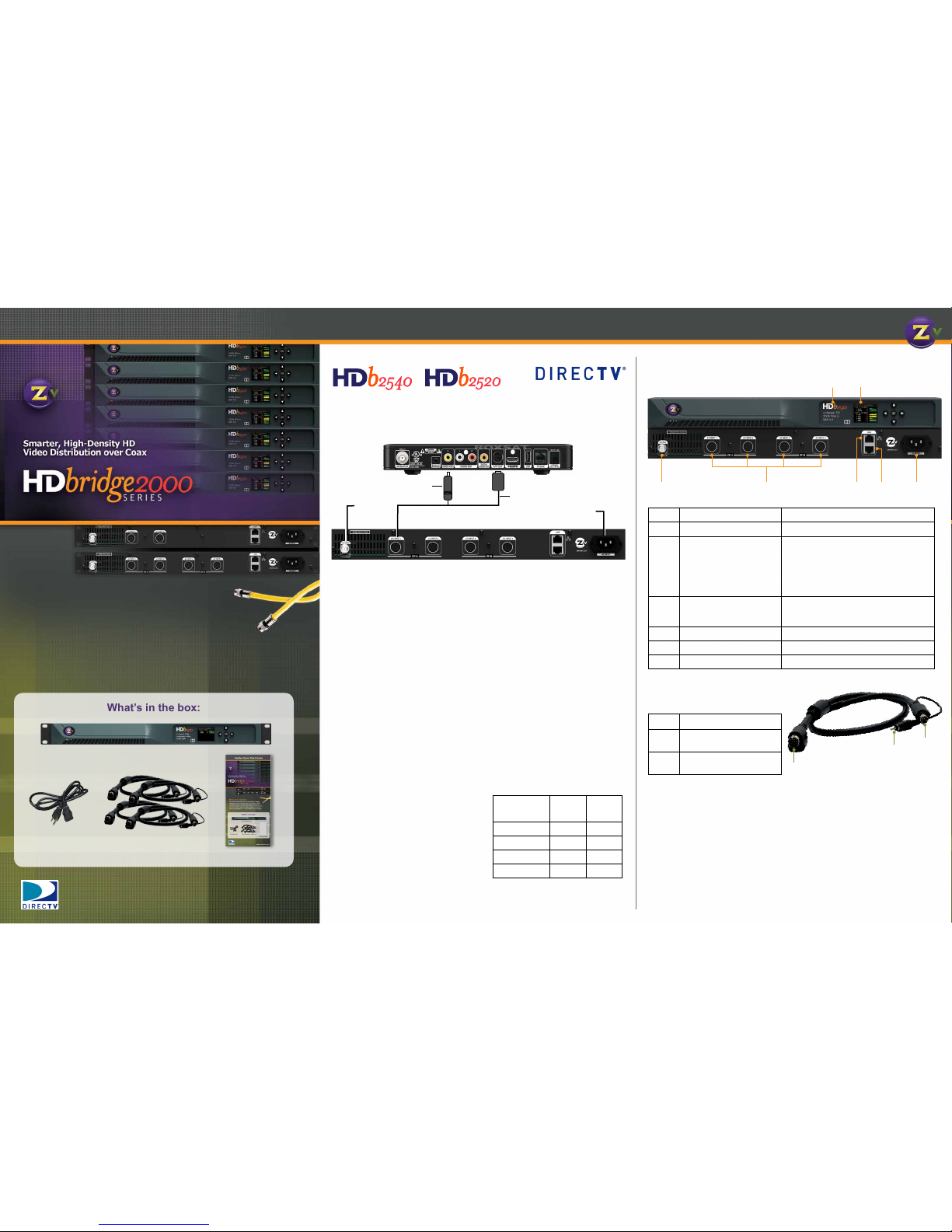
Factory default settings allow ZeeVee modulators to broadcast up to four HD
sources on RF channels 2, 3, 5 and 6 for reception at connected HDTVs.
1. Connect the power supply and apply AC power.
2. Using the A/V cable, connect the mini-DIN connector to the A/V Output
on your H25 Receiver.
3. Connect the Composite Video connector on the A/V cable to the Video
Out port for closed captions only.
4. Connect the RF Output to your RF network. Default output power can be
changed using Maestro, the web-based conguration utility.
NOTE: Default output power of HDbridge2000 is +45dBmV. Do not
connect directly to TV or you may damage the TV.
5. Set the RF input on the TV to Cable Mode (not Air or Antenna).
6. Tune HDTVs to cable channels
(see Table 1).
NOTE: Many TVs require a full
channel scan to nd the channels.
H25 A/V cables are included with this
product for use with DirecTV H25 receivers.
Standard Hydra A/V cables and VGA-DIN
cables for use with other video sources
can be purchased separately from your
distributor.
Table 1
AV Input RF #
HDTV
Channel
AV Input 1 2 2.1
AV Input 2 3 3.1
AV Input 3 5 5.1
AV Input 4 6 6.1
Basic InstallationZeeVee Quick Start Guide
Welcome to ZeeVee!
All ZeeVee products convert your video source to a digital
cable channel and broadcast it over coax to all your HDTVs.
This guide walks you through basic setup for ZeeVee HD
modulators approved for use with the DIRECTV H25 Receiver.
If you run into any problems during installation, feel free to
contact Tech Support at +1 (877) 4-ZEEVEE (1.877.493.3833).
ReceiveR-less HD
Back of H25 Receiver
A/V cable
RF Output
+45 dBMV
AC Power
Back of HDb2540
+
H25 ReceiveRs
Closed Capon
only
What’s in the box:
ZeeVee Modulator
AC Power Cord
Quick Start Guide
H25 Audio/Video Cables x4
HDb2540
Model Number Name and description of the unit.
Color Display Displays conguration and system status.
Coax Output
HDbridge 2000 Default
+45dBmV Power - do
not connect directly to
HDTVs.
Up to 2 paired, frequency-agile QAM RF
CATV output channels for up to 4 video
sources.
Output power can be set between +25 to
+45 dBmV using the front panel or the
Maestro web interface.
Audio/Video Inputs
for up to 4 sources
Video: Component
Closed Captioning: Composite
Audio: Digital, Analog
10/100 LAN Port
Conguration and remote management
10/100 LAN Port
For simplied wiring and deployment
A/C Power Input
100-240VAC / 50-60Hz
H25 A/V Cable
DIN Connector to ZeeVee
Mini-DIN Connector to
DirecTV
Composite Video Connector
for Closed Captions only
H25 A/V cables are included with this product for use with DirecTV H25 receivers.
Standard Hydra AV cables and VGA-DIN cables for use with other video sources can
be purchased separately from your distributor.
www.zeevee.com
www.zeevee.com
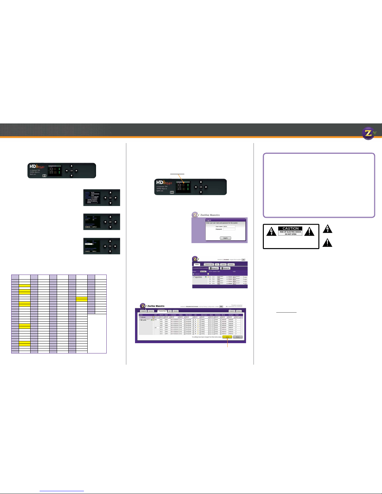
Conguration
Front Panel Conguration
In most cases, ZeeVee modulators will only require setting the RF and HDTV broadcast channels. This can be done using the Front Panel controls.
1. Unlock the panel by pressing / holding together
the arrow buttons until “Setup” lights up.
Press “OK” to enter the Conguration screen.
2. Use the the arrow buttons ( ) to go to each
item you want to congure (such as RF Number or RF
Power), then press “OK” to edit the highlighted eld.
Use the arrow buttons to scroll through
the options for that eld.
3. Once you’ve made changes, press “OK” to accept
them. You can then select the next item for
conguration.
4. When nished making changes, use the arrow
buttons ( ) to scroll down to select
“Apply,” then click “OK” to save your changes.
Note: The front panel locks automatically after a
few seconds. To make more changes, press/hold
the buttons again to re-enter the setup screen.
Setup Screen
Table 2: Cable TV Channels vs RF Frequency (MHz)
RF
Ch.
Band
(MHz)
RF
Ch.
Band
(MHz)
RF
Ch.
Band
(MHz)
RF
Ch.
Band
(MHz)
RF
Ch.
Band
(MHz)
2 54-60 27 240-246 57 420-426 87 600-606 122 780-786
3 60-66 28 246-252 58 426-432 88 606-612 123 786-792
4 66-72 29 252-258 59 432-438 89 612-618 124 792-798
5 76-82 30 258-264 60 438-444 90 618-624 125 798-804
6 82-88 31 264-270 61 444-450 91 624-630 126 804-810
95 90-96 32 270-276 62 450-456 92 630-636 127 810-816
96 96-102 33 276-282 63 456-462 93 636-642 128 816-822
97 102-108 34 282-288 64 462-468 94 642-648 129 822-828
98 108-114 35 288-294 65 468-474 100 648-654 130 828-834
99 114-120 36 294-300 66 474-480 101 654-660 131 834-840
14 120-126 37 300-306 67 480-486 102 660-666 132 840-846
15 126-132 38 306-312 68 486-492 103 666-672 133 846-852
16 132-138 39 312-318 69 492-498 104 672-678 134 852-858
17 138-144 40 318-324 70 498-504 105 678-684 135 858-864
18 144-150 41 324-330 71 504-510 106 684-690
HRC Frequencies =
Standard
Frequencies
minus 1.25 MHz
Except for:
Channel 5,
Video = 78.0 MHz
Channel 6,
Video = 84.0 MHz
IRC Frequencies =
Same as Standard
Frequencies
Except for:
Channel 5, Video =
79.25 MHz
Channel 6, Video =
85.25 MHz
19 150-156 42 330-336 72 510-516 107 690-696
20 156-162 43 336-342 73 516-522 108 696-702
21 162-168 44 342-348 74 522-528 109 702-708
22 168-174 45 348-354 75 528-534 110 708-714
7 174-180 46 354-360 76 534-540 111 714-720
8 180-186 47 360-366 77 540-546 112 720-726
9 186-192 48 366-372 78 546-552 113 726-732
10 192-198 49 372-378 79 552-558 114 732-738
11 198-204 50 378-384 80 558-564 115 738-744
12 204-210 51 384-390 81 564-570 116 744-750
13 210-216 52 390-396 82 570-576 117 750-756
23 216-222 53 396-402 83 576-582 118 756-762
24 222-228 54 402-408 84 582-588 119 762-768
25 228-234 55 408-414 85 588-594 120 768-774
26 234-240 56 414-420 86 594-600 121 774-780
Advanced Conguration with Maestro
When other changes are required, the web-based interface (Maestro) should be used.
1. Connect your computer directly to the ZeeVee modulator using a standard Ethernet cable (cross-over cable not required), or connect the unit to any LAN that has a
DHCP server.
2. After a few moments, an IP address will appear at the top of the front panel display.
3. Using any web browser (Firefox or Chrome preferred), go to the IP address to launch
Maestro, the conguration tool.
4. You will be directed to a login page:
User Name: admin
Default Password: admin
The User Name will always be
“admin.” The default password is
“admin” but it can be changed in
the conguration tool.
NOTE: Login is case-sensitive.
5. Tabs across the top allow for different conguration actions.
Click on “Channel Plan” to set the
RF number, channel names, video
source, etc.
Refer to Table 2 for help selecting
channel settings.
6. Click “Apply” to save your changes.
Settings are stored in the unit and not
lost on power-down.
Click Apply to save
your changes.
Conguration Screen
Active Conguration Screen
www.zeevee.com
CAUTION: TO REDUCE THE RISK OF ELECTRIC SHOCK
DO NOT REMOVE THE COVER (OR BACK).
NO USER SERVICABLE PARTS INSIDE.
REFER SERVICING TO QUALIFIED SERVICE PERSONNEL.
General Information
Contact ZeeVee
For support, repairs and warranty service: +1-877-4ZEEVEE (1-877-493-3833)
Warranty
Limited Two Year Warranty
ZeeVee warrants your ZeeVee Modulator (HDbridge2000 MODEL NUMBERS HDB2540-NA, HDB2520NA) against defects in materials and workmanship for a period of two years from the date of purchase. Visit www.zeevee.com for complete warranty details.
To Get Warranty Service
Warranty service will be provided by ZeeVee. If you believe you need service for your ZeeVee Modulator (HDbridge2000 MODEL NUMBERS HDB2540-NA, HDB2520-NA), please contact ZeeVee directly
by calling ZeeVee Support at +1 (877) 493-3833. If it is determined that the product needs to be returned for service or exchange, you will receive a Return Material Authorization (“RMA”) number. Our
agents will help you through the process through which you can return the product. ZeeVee is not
responsible for Customer products received without an RMA number and may reject such products.
To Get Out-Of-Warranty Service
To obtain out-of-warranty service for your ZeeVee Modulator (HDbridge2000 MODEL NUMBER
HDB2540-NA, HDB2520-NA), please contact ZeeVee by calling ZeeVee Support at +1 (877) 493-3833
for information on the possibility of and any costs for repair or replacement of out-of-warranty products. No agent, company, dealer, distributor, or person is authorized to change, modify, or extend the
terms of these warranties in any manner.
INSTRUCTIONS PERTAINING TO A RISK OF FIRE, ELECTRIC SHOCK, OR INJURY TO PERSONS
Important Safety Instructions. Save These Instructions.
WARNING: When using electronic products, basic precautions should always be followed, including:
1. Keep these instructions.
2. Heed all warnings.
3. Follow all instructions.
4. Do not use this apparatus near water.
5. Clean only with dry cloth.
6. Do not block any ventilation openings. Install in
accordance with the manufacturer’s instructions.
7. Do not install near any heat sources such as radiators,
heat registers, stoves, or other apparatus (including
ampliers) that produce heat.
8. Do not defeat the safety purpose of the polarized or
grounding-type plug. A polarized plug has two blades with
one wider than the other. A grounding type plug has two
blades and a third grounding prong. The wide blade or
the third prong is provided for your safety. If the provided
plug does not t into your outlet, consult an electrician for
replacement of the obsolete outlet.
9. Power cord must be accessible to allow for the removal
of power from the unit.
10. Protect the power cord from being walked on or pinched,
particularly at plugs, convenience receptacles, and the
point where they exit from the apparatus.
11. Unplug the apparatus during lightning storms or when
unused for long periods of time.
12. Only use attachments/accessories specied by the
manufacturer.
13. Refer all servicing to qualied service personnel. Servicing is required when the apparatus has been damaged in
any way, such as power-supply cord or plug is damaged,
liquid has been spilled or objects have fallen into the apparatus, the apparatus has been exposed to rain or moisture, does not operate normally, or has been dropped.
14. WARNING: To reduce the risk of re or electric shock do
not place this apparatus in a position where it is exposed
to dripping or splashing liquids, rain, moisture, or
excessively high humidity. Objects containing liquid shall
not be placed in proximity to the unit such that they
present a risk of spillage onto the apparatus.
The lightning ash with arrowhead symbol,
within an equilateral triangle, is intended to
alert the user to the presence of uninsulated
“dangerous voltage” within the product’s
enclosure that may be of sufcient magnitude
to constitute a risk to persons.
The exclamation point within an equilateral
triangle is intended to alert the user to the
presence of important operating and maintenance (servicing) instructions in the literature
accompanying the product.
FCC Statement
FCC Compliance and Advisory Statement: This hardware device complies with Part 15 of the FCC rules. Operation is subject to the
following two conditions: 1) this device may not cause harmful interference, and 2) this device must accept any interference received
including interference that may cause undesired operation. This equipment has been tested and found to comply with the limits for a
Class A digital device, pursuant to Part 15 of the FCC Rules. These limits are designed to provide reasonable protection against harmful
interference in a commercial installation. This equipment generates, uses, and can radiate radio frequency energy and, if not installed
or used in accordance with the instructions, may cause harmful interference to radio communications. However there is no guarantee
that interference will not occur in a particular installation. If this equipment does cause harmful interference to radio or television reception, which can be determined by turning the equipment off and on, the user is encouraged to try to correct the interference by one or
more of the following measures: 1) reorient or relocate the receiving antenna; 2) increase the separation between the equipment and
the receiver; 3) connect the equipment to an outlet on a circuit different from that to which the receiver is connected; 4) consult the
dealer or an experienced radio/TV technician for help. Any changes or modications not expressly approved by the party responsible
for compliance could void the user’s authority to operate the equipment. Where shielded interface cables have been provided with the
product or specied additional components or accessories elsewhere dened to be used with the installation of the product, they must
be used in order to ensure compliance with FCC regulations.
70-00030-00 Rev A
 Loading...