


GS8
Modual Gateway
User’s Manual
Manual Part Number 96-00524-01
Zed-3
501 Valley Way
Milpitas CA 95035
USA
+1-408-587-9333
http://www.zed-3.com

Notice
The information contained in this document is subject to change without notice.
Zed-3 makes no warranty of any kind with regard to this material, including, but not limited
to, the implied warranties of merchantability and fitness for a particular purpose. Zed-3 shall
not be liable for errors contained herein or for incidental or consequential damages in
connection with the furnishing, performance, or use of this material.
Zed-3 assumes no responsibility for the use or reliability of interconnected equipment that is
not furnished by Zed-3.
This document contains proprietary information which is protected by copyright. The
contents of this manual and the associated software are the property of Zed-3, and all rights
are reserved. No part of this document may be photocopied, reproduced, stored in any
computer format, translated to another language, or publicly displayed without the prior
written consent of Zed-3.
The information contained herein has been prepared by Zed-3 solely for use by Zed-3’ss
employees, agents, and customers. Dissemination or use of the information or concepts
contained herein to or by other parties is prohibited without prior written consent from Zed-3.
Zed-3, the Zed-3 logo, the Zed-3 mark,GS8, CN2x2, CN2x4, SE150, SE150P, SE150+, SE150,
SE500, and SEME are trademarks of Zed-3 and may be registered trademarks in certain
countries. All other names may be trademarks or registered trademarks of their respective
owners.
Revision History
Manual Release Firmware Vision Release Date
1.0 1.0.0 13 June 2008
1.1 1.0.6.7 06 January 2009

Contents
Product Introduction . . . . . . . . . . . . . . . . . . . . . . . . . . . . . . . . . . . . . . . . . . 1
1.1 Product Introduction . . . . . . . . . . . . . . . . . . . . . . . . . . . . . . . . . . . . . . . . . . . 1
1.2 Technical Specifications. . . . . . . . . . . . . . . . . . . . . . . . . . . . . . . . . . . . . . . . . 1
1.3 Basic Features . . . . . . . . . . . . . . . . . . . . . . . . . . . . . . . . . . . . . . . . . . . . . . . . . 3
1.4 Profile . . . . . . . . . . . . . . . . . . . . . . . . . . . . . . . . . . . . . . . . . . . . . . . . . . . . . . . . 3
1.5 Interface Module. . . . . . . . . . . . . . . . . . . . . . . . . . . . . . . . . . . . . . . . . . . . . . . 5
Device Installation . . . . . . . . . . . . . . . . . . . . . . . . . . . . . . . . . . . . . . . . . . . . 7
2.1 Installation Requirements . . . . . . . . . . . . . . . . . . . . . . . . . . . . . . . . . . . . . . . 7
2.2 Preparations. . . . . . . . . . . . . . . . . . . . . . . . . . . . . . . . . . . . . . . . . . . . . . . . . . . 9
2.3 Installation Procedures . . . . . . . . . . . . . . . . . . . . . . . . . . . . . . . . . . . . . . . . . 9
Web Management System . . . . . . . . . . . . . . . . . . . . . . . . . . . . . . . . . . . . . 11
3.1 Login . . . . . . . . . . . . . . . . . . . . . . . . . . . . . . . . . . . . . . . . . . . . . . . . . . . . . . . . 11
3.2 Web Management System Interface . . . . . . . . . . . . . . . . . . . . . . . . . . . . . 13
3.3 Menu Structure . . . . . . . . . . . . . . . . . . . . . . . . . . . . . . . . . . . . . . . . . . . . . . . 14
Monitor . . . . . . . . . . . . . . . . . . . . . . . . . . . . . . . . . . . . . . . . . . . . . . . . . . . . 15
4.1 System Info . . . . . . . . . . . . . . . . . . . . . . . . . . . . . . . . . . . . . . . . . . . . . . . . . . 15
4.2 Line Status . . . . . . . . . . . . . . . . . . . . . . . . . . . . . . . . . . . . . . . . . . . . . . . . . . . 16
4.3 Active Calls. . . . . . . . . . . . . . . . . . . . . . . . . . . . . . . . . . . . . . . . . . . . . . . . . . . 18
4.4 Call Records . . . . . . . . . . . . . . . . . . . . . . . . . . . . . . . . . . . . . . . . . . . . . . . . . . 18
Line Settings. . . . . . . . . . . . . . . . . . . . . . . . . . . . . . . . . . . . . . . . . . . . . . . . 20
5.1 IP Line. . . . . . . . . . . . . . . . . . . . . . . . . . . . . . . . . . . . . . . . . . . . . . . . . . . . . . . 21
5.2 GSM Line . . . . . . . . . . . . . . . . . . . . . . . . . . . . . . . . . . . . . . . . . . . . . . . . . . . . 23
5.3 CDMA Line. . . . . . . . . . . . . . . . . . . . . . . . . . . . . . . . . . . . . . . . . . . . . . . . . . 25
5.4 FXO Line . . . . . . . . . . . . . . . . . . . . . . . . . . . . . . . . . . . . . . . . . . . . . . . . . . . . 26
Call Settings . . . . . . . . . . . . . . . . . . . . . . . . . . . . . . . . . . . . . . . . . . . . . . . . 27
6.1 Matching Rules . . . . . . . . . . . . . . . . . . . . . . . . . . . . . . . . . . . . . . . . . . . . . . . 27
6.2 Routing Matching Rules . . . . . . . . . . . . . . . . . . . . . . . . . . . . . . . . . . . . . . . 28
6.3 Route. . . . . . . . . . . . . . . . . . . . . . . . . . . . . . . . . . . . . . . . . . . . . . . . . . . . . . . . 29
6.4 Alter. . . . . . . . . . . . . . . . . . . . . . . . . . . . . . . . . . . . . . . . . . . . . . . . . . . . . . . . . 30
6.5 Filter . . . . . . . . . . . . . . . . . . . . . . . . . . . . . . . . . . . . . . . . . . . . . . . . . . . . . . . . 34
6.6 Schedule . . . . . . . . . . . . . . . . . . . . . . . . . . . . . . . . . . . . . . . . . . . . . . . . . . . . . 36
6.7 System. . . . . . . . . . . . . . . . . . . . . . . . . . . . . . . . . . . . . . . . . . . . . . . . . . . . . . . 38
Administration . . . . . . . . . . . . . . . . . . . . . . . . . . . . . . . . . . . . . . . . . . . . . . 40
7.1 Change Password . . . . . . . . . . . . . . . . . . . . . . . . . . . . . . . . . . . . . . . . . . . . . 40
GS8 Modular Gateway User’s Manual 1

Contents
7.2 Network Setting . . . . . . . . . . . . . . . . . . . . . . . . . . . . . . . . . . . . . . . . . . . . . . 41
7.3 Time Setting. . . . . . . . . . . . . . . . . . . . . . . . . . . . . . . . . . . . . . . . . . . . . . . . . . 41
SMS. . . . . . . . . . . . . . . . . . . . . . . . . . . . . . . . . . . . . . . . . . . . . . . . . . . . . . . 44
8.1 Route. . . . . . . . . . . . . . . . . . . . . . . . . . . . . . . . . . . . . . . . . . . . . . . . . . . . . . . . 45
8.2 GTXT Client. . . . . . . . . . . . . . . . . . . . . . . . . . . . . . . . . . . . . . . . . . . . . . . . . . 47
8.3 Configuration . . . . . . . . . . . . . . . . . . . . . . . . . . . . . . . . . . . . . . . . . . . . . . . . 48
8.4 Send Test Message . . . . . . . . . . . . . . . . . . . . . . . . . . . . . . . . . . . . . . . . . . . . 50
8.5 Received Messages . . . . . . . . . . . . . . . . . . . . . . . . . . . . . . . . . . . . . . . . . . . . 50
Maintenance . . . . . . . . . . . . . . . . . . . . . . . . . . . . . . . . . . . . . . . . . . . . . . . . 52
9.1 System Reboot. . . . . . . . . . . . . . . . . . . . . . . . . . . . . . . . . . . . . . . . . . . . . . . . 52
9.2 Config Management . . . . . . . . . . . . . . . . . . . . . . . . . . . . . . . . . . . . . . . . . . 52
9.3 Upgrade Firmware . . . . . . . . . . . . . . . . . . . . . . . . . . . . . . . . . . . . . . . . . . . . 53
9.4 Auto Attendant . . . . . . . . . . . . . . . . . . . . . . . . . . . . . . . . . . . . . . . . . . . . . . . 54
9.5 Diagnostic Tools . . . . . . . . . . . . . . . . . . . . . . . . . . . . . . . . . . . . . . . . . . . . . . 55
GS8 Disaster Recovery System. . . . . . . . . . . . . . . . . . . . . . . . . . . . . . . . . 56
Glossary . . . . . . . . . . . . . . . . . . . . . . . . . . . . . . . . . . . . . . . . . . . . . . . . . . . 57
GS8 Modular Gateway User’s Manual 2

Product Introduction
1.1 Product Introduction
Zed-3 GS8 is a Modular Gateway which has prefect performance, rich interfaces, and interface
cards plug capacity. GS8 supports GSM/CDMA, SIP, FXO interface, so it can be connected with
GSM/CDMA, VoIP and PSTN networks, allows calls to freely transfer between these interfaces.
GS8 permits flexible call routing and call restriction settings to provide users calling strategy
based on their own requirements. The web-based management platform dramatically reduces
complication of users' operations.
1. Product Introduction
Chapter 1
GS8 are compatible with most SIP-based IP-PBX and traditional telephony system. When there
is no PBX, it can be deployed alone or in a group. At the same time, this product can be connected
to local PSTN network directly since it supports most countries and areas' telephone protocols.
Zed-3 sales GS8 and provides technical supports over the world.
1.2 Technical Specifications
1

Specifications Description
• Up to 4 GSM ports(900/1800 MHz, 850/1900MHz )
1. Product Introduction
System capacity
Hardware
specification
Interface card
capacity
Network interface
Voice ca pacity
• Up to 8 FXO ports (loop start)
• Any combination of interface cards
• 8 simultaneous calls
• 1 reset button
• 4 extended slots
• 2 system indicator lights
• 2 LED per FXO card and GSM/CDMA card.
• GSM/CDMA module: SMA connector
• FXO module: RJ11 connector
• 4 extended slots
- 2-port FXO card
- 1-port GSM/CDMA card
- 1-port GSM/CDMA card
• one 10/100M LAN port
• Codec: G.711 A-Law/U-Law?G.729?G.723.1
• Confort noise, voice activity detection, echo cancellation,
jitter buffer.
Physical
characteristics
Operating
environment
• DTMF Relay: In-band DTMF Relay, RFC-2833,SIP INFO
• Dimesion: 440mm x 225mm x 45mm (17.3”x8.9”x1.8” )
• Weight: 3.8kg ( 8.41 lb )
• Power: AC-DC power adapter
• Input: ATX PS,AC 100 ~ 240 V @ 47 ~ 63 Hz
• Output: DC-5V
• Power consumption: Max.20 Watt
• Operating temperature: 10 ~ 40 °C(50 °F ~ 104 °F)
• Storage temperature: 0 ~ 50 °C(32 °F ~ 122 °F)
• safety: meet
• FCC Part 68
• electromagnetic interference: meet FCC Part 15A
• RoHS: compatible
2
1.3 Basic Features
• Support SIP, meet RFC3261 standard, compatible with most SIP-based IP-PBXs
• Support flexible SIP calling, support connecting to other SIP devices like IP-PBXs in register
or unregister way.
• Support GSM , CDMA and FXO interface via interface cards.
• Have Modular interface, support mix-plug of interface cards.
• Support flexible secondary dialing and DID function
• Support flexible call routing, freewill transfer between any two interfaces.
• Flexible call restriction.
• Powerful number transform includes head-trim, tail-trim, replacement, and number segment
way.
• Full calling strategy management: set call schedule based on different time segments.
• Cascade and extend capacity in a unregister way
• Plenty system monitor: line status, current call, CDR, system status.
• Easy-use of web configuration and management system.
1. Product Introduction
• Powerful safety management, upload/download configurations, fireware update, disaster
recovery etc.
1.4 Profile
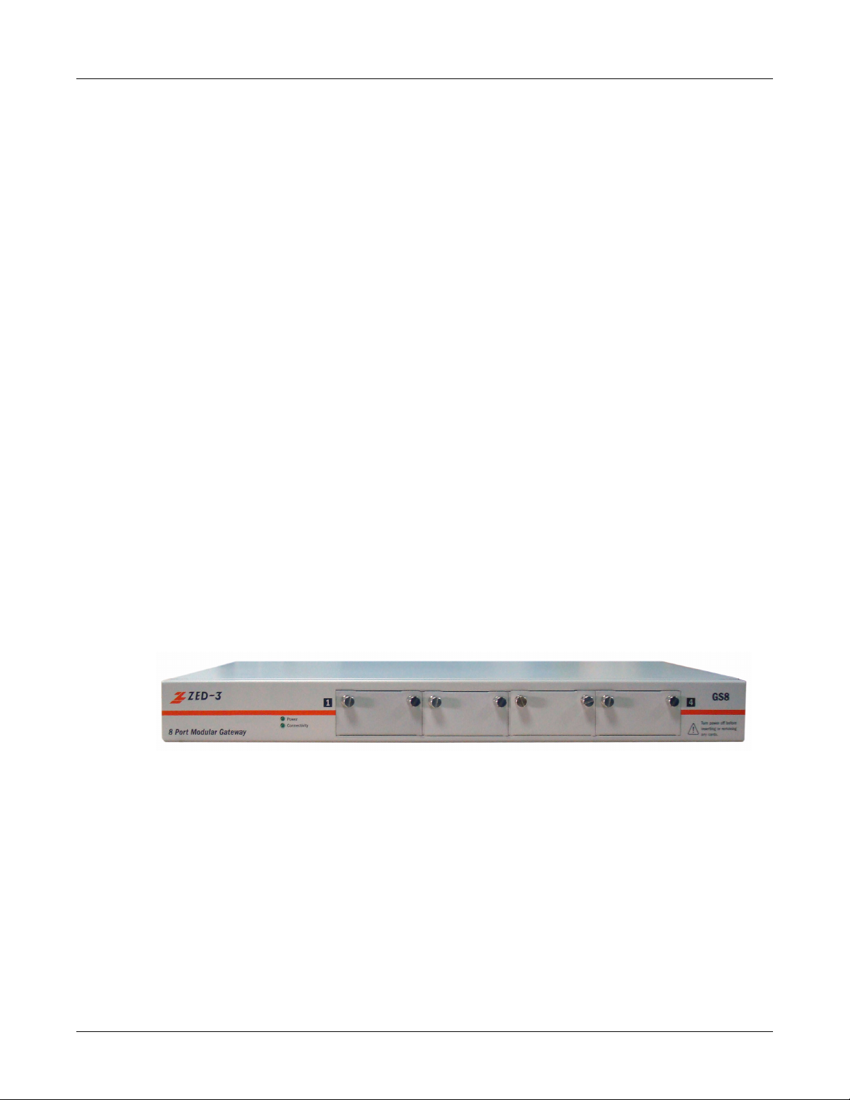
1.4.1 Appearance
Figure 1-1 GS8 appearance
1.4.2 Front View
3
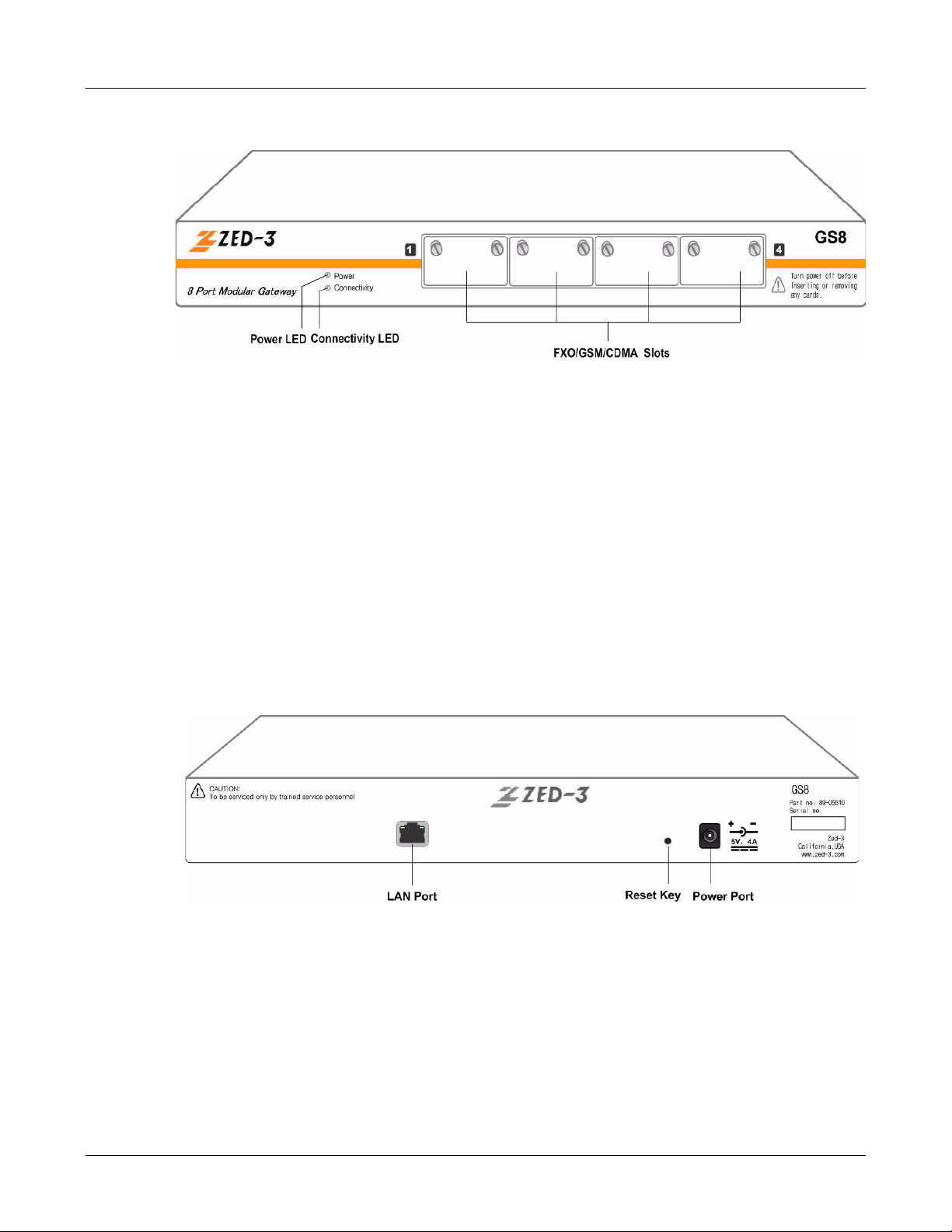
Figure 1-2 GS8 front panel
• Two LED indicators on the front panel of GS8 for system status:
- Power: power indicator, be green when power-on.
- Connectivity: network connectivity indicator.
* Be red if there is no Ethernet connectivity.
1. Product Introduction
* Be orange if routing is blocked because of the failure of SIP subscriber register.
* Be green if any one of the trunks registered (by SIP) successfully.
• 4 extended slots which can hold two FXO cards and two GSM cards.
1.4.3 Back View
Figure 1-3 GS8 back panel
All ports here:
• LAN port: GS8 connects network via this port.
• Reset button: reset the configuration to factory defaults (includes network configuration).
Press it for 6 seconds when system is running.
• Power connectivity: connect to power adapter.
4
1.5 Interface Module
GS8 has four extended slots which support three kinds of cards: GSM card, CDMA and FXO card.
The mix is also supported.
One GSM card supports one GSM call, one CDMA card supprts one CDMA call, but one FXO
card has two FXO ports, so it supports two FXO calls. In total, GS8 supports eight FXO calls or
four GSM calls or four CDMA calls.
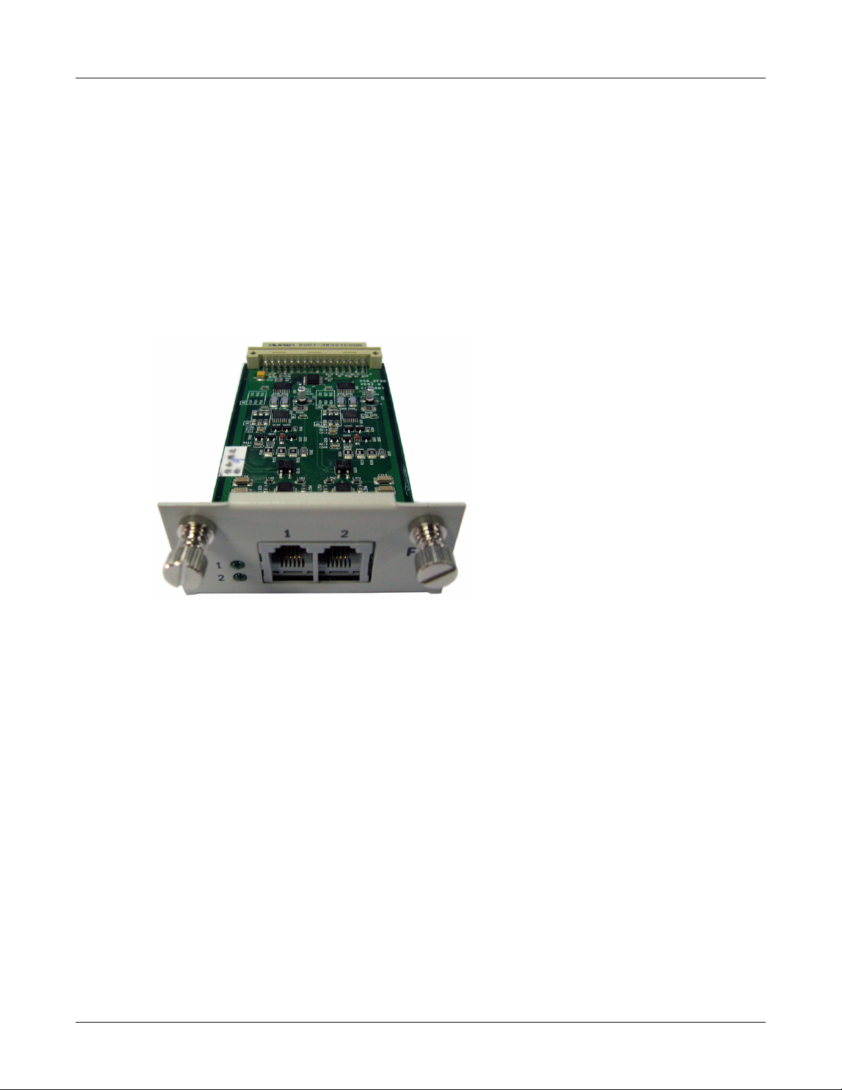
1.5.1 FXO Interface Card
FXO interface card can be set on your PBX or telephone exchange SPC switch as an extension.
1. Product Introduction
Figure 1-4 FXO interface card
There are two FXO ports and two indicators per FXO card, the corresponding light is on when the
line is off-hook.
1.5.2 GSM/CDMA Interface card
GSM or CDMA interface modules: there are two LED lights to show running status:
5

Figure 1-5 GSM/CDMA interface card
A External Antenna
1. Product Introduction
• Signal: be red or green. be red if there is no signal. be off for 500ms then be red for 500ms if
there is no SIM card. be orange when there is SIM card and signal but the register to service
provider's network failed. be green if every thing is ok.
• Service: be red or green. be off if there is no call. be off for 500ms then be red for 500ms if
there is no SIM card. be green when there is a call.
6

Device Installation
Unpack the unit and verify shipment content with the packing list :
• One GS8 equipment.
• One power adapter and one power cable.
2. Device Installation
Chapter 2
• One Ethernet cable.
• One copy of quick start guide.
• One copy of e-manual.
• One Zed-3 pen as a gift.
• Accessories package: six M6 screws, eight M4 screws, two GS8 fixers.
Note: If there is any missing or damage, contact the seller or Zed-3 sales immediately and save
all packages for the repackaging if need.
2.1 Installation Requirements
2.1.1 Power Requirements
• Power-off before installation, dismantlement or movement.
• The electric outlet shall be installed near the equitment and shall be easily accessible in case
of emergency.
2.1.2 Anti-static Requirements
• If the device's power line connects to external cable, take necessary anti-static actions please.
• Anti-static Requirements
- Static will damage the circuit or the whole machine seriously if static exceed the limitation,
so make sure the ground bus well enough.
7

- Static inside body will result in damage too, so please wear anti-static wristband if you
have.
2.1.3 Environment Requirements
2.1.3.1 Basic Conditions
Keep the GS8 equipment in a room which has proper control of temperature and humidity, watch
out the conductivity of the shelf. Too high or too low humidity will cause short circuit or fire. At the
same time, the conductive property of rack is also considerable.
Place the equipment on a rack (if possible) which is near stable and liable power in an anti-fire,
anti-humidity, anti-dust, and anti-thief room.
2.1.3.2 Temperature, Humidity, and Illumination
Suggestions:
• Temperature: 0 ~ 40
2. Device Installation
• Relative humidity: 5~ 95RH without coagulation
• Illumination: light, 500 ~750 lx, light enough for operations.
High humidity will affect the insulating efficiency of insulating materials and also cause the rust of
metals. Low humidity will make insulating gasket shrink, loose the fixed bolts, and scrape up
static. Long period of high temperature will accelerate components' aging, lower the reliability and
reduce the useful time dramatically.
2.1.3.3 Air Quality
The air particulate may enter the equipment through ventholes. Too much dust will cause
short-circuit, so the suggestion is less than 180mg/m3. In machinery room, printer and
Photocopiers shall be placed away from the power provider in case of floating particulate. Please
put it in the diagonal corner.
Keep the room clean, for the dust will cause static and bad connections between little
components
2.1.3.4 Ventilation Requirements
There are thermal discharge holes in the back and side side, so keep more than 100mm from
other stuffs for thermal discharging.
2.1.3.5 Safety
There must be some safety precautions like securities or other effective anti-thief actions. The
lightning rod is well connected to the ground, the ground bus' diameter must be more than 5mm.
For seismal zones, there must be anti-earthquake measurements, like fixed balustrade for the
rack.
8

2.2 Preparations
2.2.1 Network Resources
GS8 shall be connected with intra-company network or Internet for different usages. Test your
network connectivity and provide a port for this equipment. It is usually connected to a switch or
a router.
2.2.2 IP Address
Get an IP address for your GS8. the setting of IP address, see 3.1.1set GS8's IP address.
Note: Static IP address is recommended, no matter public or private address. (except DDNS ).
2.2.3 Ethernet Cable
Get a standard RJ-45 cable for GS8.
2. Device Installation
2.2.4 External Line
2FXO card is necessary if you want to call PSTN from GS8, connect its FXO port with PSTN with
a cable.
Prepare a GSM card if you want to call mobile phones from GS8.
2.2.5 Other Soft-switch Accounts
Ask for soft switch accounts and register information like phone number, password, register proxy
address, proxy address, register port, external proxy address, register expiration time etc.
2.2.6 Network Topology
Build your network topology based on GS8's location and connectivities.
2.2.7 Line Adjustment
Extend the external lines and cables to reach GS8's ports, if they are too far from the equipment.
2.3 Installation Procedures
GS8 equipment shall be placed on a table or a rack, install it as below steps.
9

Note: Do not put any heavy thing on the equipment to avoid any damage of the base.
2.3.1 Network Connection
Connect the cable with Ethernet LAN port on the back side.
2.3.2 Connect out Line
• Connect analog line with the port of 2FXO card on GS8
• If there is a GSM/CDMA card, connect an antenna with GSM/CDMA port. Better way is with
a coaxial cable.
• If there are several wireless cards, these cards may share one public antenna.
2.3.3 Power Connection
1. Connect the power line with the power port on the back side.
2. Device Installation
2. Connect the other end with outlet nearby.
2.3.4 Power On
After all these steps, power on.
All LED indicators are off at the beginning, then the power indicator is green all the time.
10

Web Management System
3.1 Login
Login to GS8 Web Server with IE browser (1024*768 recommended) and make configurations
like this:
3. Web Management System
Chapter 3
1. Open IE browser and enter IP address in the address field.
GS8 has a default address: 192.168.0.100. If the default address has been changed, gain it like
below: ( if you can not login, see 3.1.1 change GS8's IP address)
• Dail “***” and input password "23646" when you hear the dialing tone of AA after calling
in through FXO port of GS8, and the equipment will show you the IP address. the
SpreeCode and password used here are default, you may change them on the page of
AA at Call Settings-System Settings after loging into the web management system.
• Or Press Reset button for 6 seconds and reset the configurations to the factory default
(including the IP address recovered to default 192.168.0.100 ).
Note: The Reset button will reset all configurations, not only the IP address.
2. Input user name and password in the pop-up window. ( see figure 3-1)
11
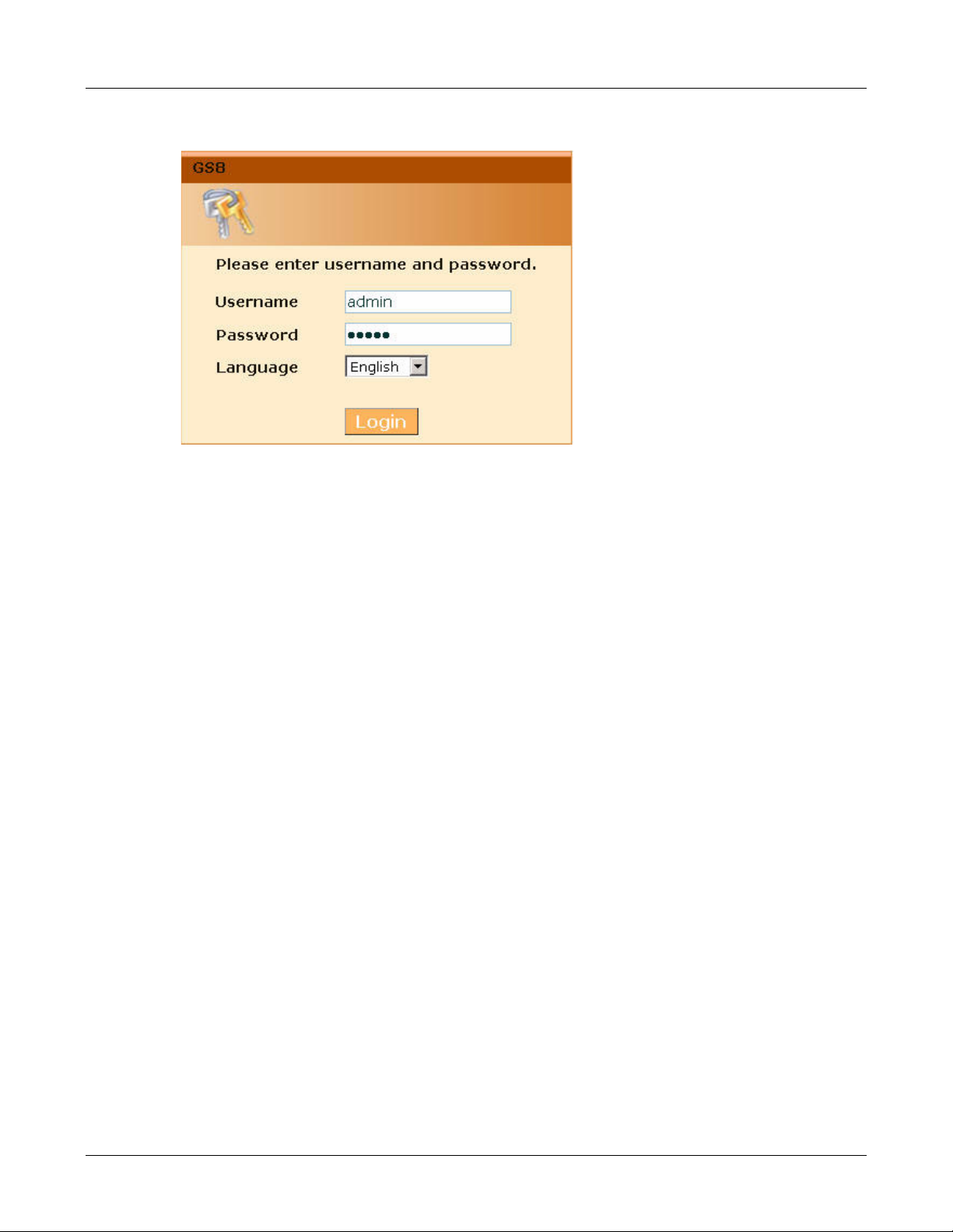
Figure 3-1 Login window
• Administrator: the default user name and password is "admin".
3. Web Management System
Change administrator's password in the Adminstration > Change Password menu after login.
3.1.1 Change GS8's IP Addresss
Any operation (including initialization) on configurations shall be made in the GS8's web
management system. You can not login to the system if your PC's IP address does not belong to
the same network segment as the equipment's. So the simplest way is to change your PC's IP
address.
As below:
1. Change your PC's IP address to the same network segment (for example: 192.168.0.120 )
2. Login to GS8: visit the default "192.168.0.100" with IE browser and login with "admin".
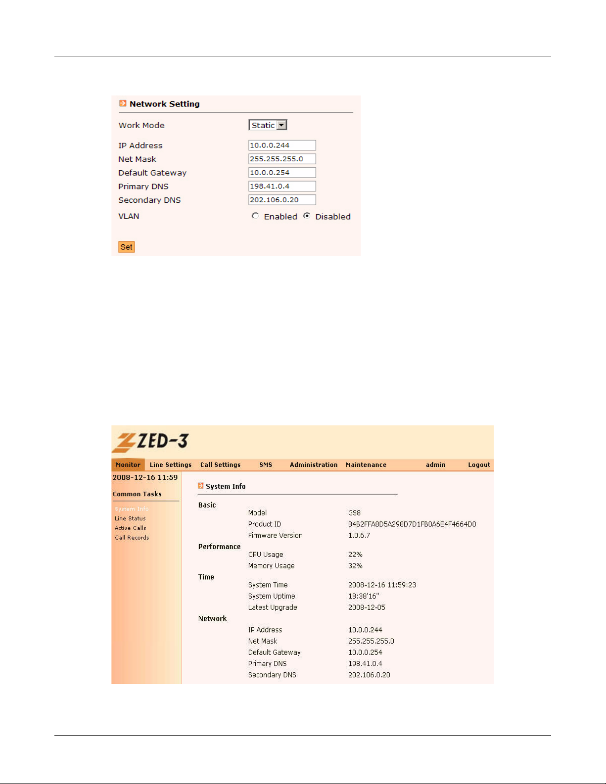
3. Click and enter Administration> Network Setting menu, change the IP Address, Net
mask, Default gateway and DNS based on your real situation.
12
3. Web Management System
Figure 3-2 Change GS8's IP address
4. After setting, press [Set] button to make it work. roll your PC's IP address back.
5. Login to the web management system with the new IP address.
3.2 Web Management System Interface
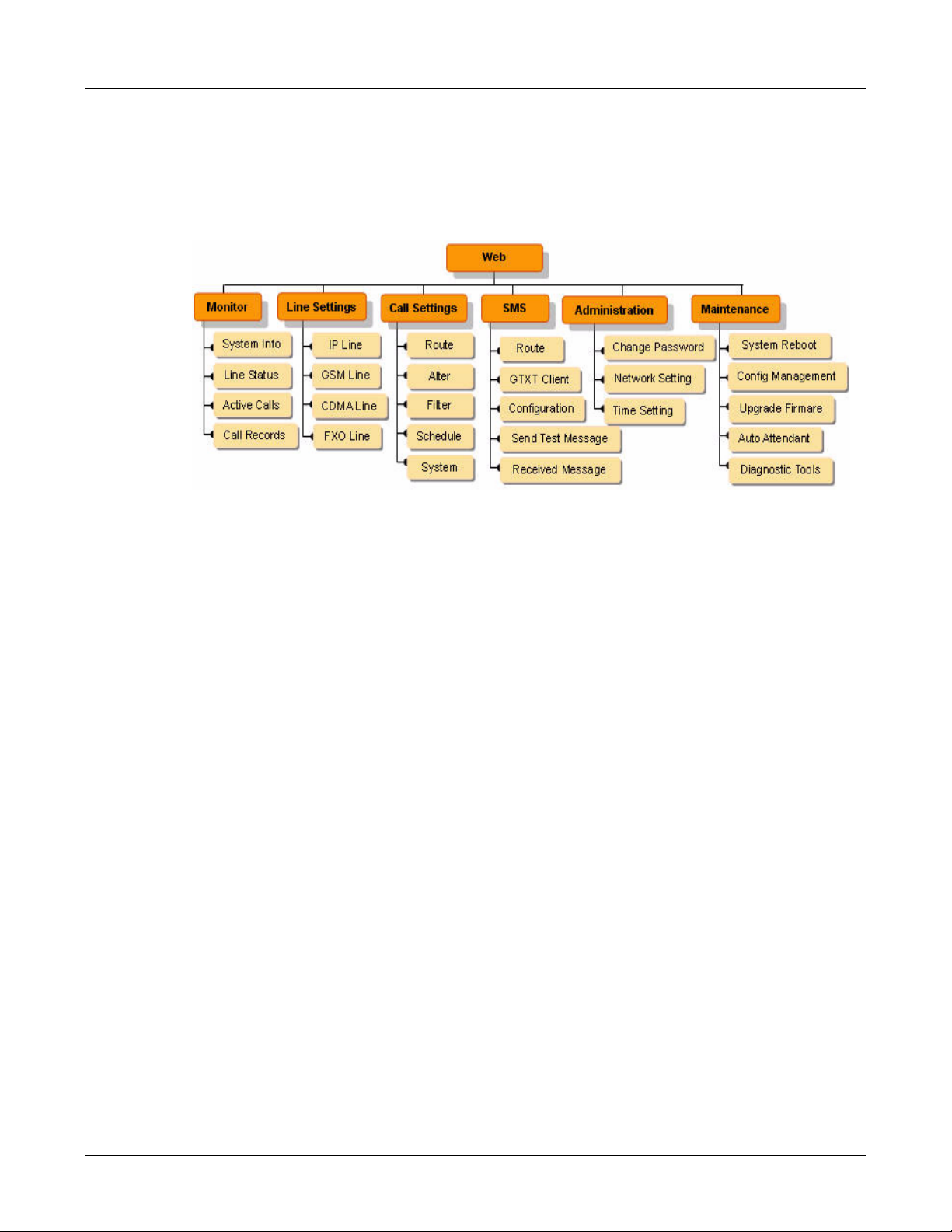
There are six main menus on the top of the web management system's main page, they are
Monitor, Line Settings, Call settings, Administration,and Maintenance.
Click each main menu to show its sub-menu, click the sub-menu to see the setting pages.
Figure 3-3 Web Management System main interface
13
The system supports Chinese and English. Here is the English version.
3.3 Menu Structure
Figure 3-4 Menu Structure
3. Web Management System
14
Monitor
The Monitor menu in Web Management System provides System Info, Line Status, Active
CAlls, Call Records etc..
4.1 System Info
4. Monitor
Chapter 4
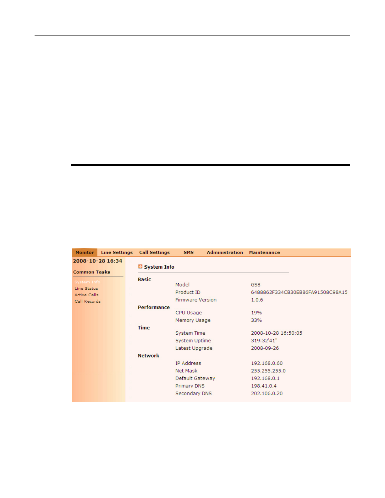
Login to Web Management System or on the page of Monitor > System Info, there is system
information about product model, firmware version, licence and resource usage etc.
Figure 4-1 System Monitor - System Info page
The parameters are:
• Basic
15

- Model: GS8.
- Product ID: the unique number of GS8 equipment.
- Firmware version: the current version of the equipment, like 1.0.6.7.
• Performance
- CPU Usage: the current usage of CPU.
- Memory Usage: the current usage of memory.
• Time
- System Time: the current system time.
- System Uptime: the duration from last start-up.
- Latest Upgrade Time: the lastest time of upgrade.
• Network
- IP Address: the current IP address of the GS8 equipment.
- Net Mask: the netmask now used.
- Default Gateway: the IP address of the default gateway now used.
4. Monitor
- Primary DNS: the IP address of primary DNS now used.
- Secondary DNS: the IP address of secondary DNS now used.
4.2 Line Status
Trunk lines are very important basic resources for GS8 system. All calls must have trunk lines to
be made. GS8 has two kinds of trunk line: IP line and interface card line. You must use SIP
protocol to make a call on IP line, you may add, delete, or modify IP line by yourself. Maximal
capacity is 10 register IP lines and 10 unregister IP lines. Interface card line is the lines which
provided by interface card. Now we have GSM/CDMA and FXO cards. The number of interface
card lines is fixed since the card is fixed, so you can not add, or delete any interface card lines,
but only change the settings.
The system will monitor all these lines' status, and provide monitor information to the
administrator for management.
Monitor > Line Status menu monitors all trunk lines, and classifies them into IP Line, PSTN Line
and GSM/CDMA line as figure 4-2.
16

4. Monitor
Figure 4-2 Monitor - Line Status page
• Type : the line type, includes: IP (Register IP or unregister IP ), FXO , GSM/CDMA or GTXT.
Note: GTXT only shows registered GTXT (unregistered GTXT will not be shown). red font
means unavailable line.
• ID: the sequence number of the line ( for example: "slot1-2" means the 1st card's 2
nd
port).
• Phone Number: the phone number assigned to this line.
• Status: the status of the line
- For IP Line: includes Avaialbe, Invalid, Full, Register fails, Registering.
- For GSM/CDMA line: includes Available, Invalid, On used, Register fails, Registering,
Signal low, No SIM Card
- For FXO line: includes Available, Invalid, On used.
Note: GS8 monitors SIM cards of wireless modules (including GSM and CDMA), and all
status will be shown at the Status field. For IP Line, GS8 checks whether unregister IP lines are
ready every 10 minutes and shows the result at Status field.
• Signal Strength(0~31): the realtime signal checking of GSM/CDMA line, current scale is from
0 to 31. for example, means the signal magnitude is 16 and be checked every one
minute.
17
 Loading...