

Zeck Audio CHAMP 2.250, CHAMP 2.500, CHAMP 2.350, CHAMP 4.120, CHAMP 4.250X Owner's Manual

CHAMP
2 - a n d 4 - ch a n n e l p owe r a m p l i f i e r s
series
2.250
•
2.350 • 2.500 • 4.120 • 4.250X
Bedienungsanleitung
Owner‘s manual
BRIDGE MODE
ONON
PROTECT
SIGNAL LIMIT
2
0
4
6
8
8
10
12
14
18
24
-dB
LIMITON
PROTECT
SIGNAL
POWER ON
-dB
2
0
4
6
8
8
10
12
14
18
24
CH 3 + 4
CHANNEL3 CHANNEL4
BRIDGE MODE
CH 1+2
PROTECT
SIGNAL LIMIT
2
0
4
6
8
8
10
12
14
18
24
CHANNEL 1
-dB
LIMITON
PROTECT
SIGNAL
CHANNEL2
-dB
2
0
4
6
8
8
10
12
14
18
24
AMP
4 x 250 W POWER AMPLIFIER X-OVER
250

2
CHAMP Series owner‘s manual © Zeck Audio 2000
K000001A01
-
Sicherheitshinweise
Um Gefährdung durch elektrischen Schlag zu vermeiden, darf das Gehäuse nicht geöffnet werden.
Es benden sich keine vom Benutzer reparierbaren Teile im Inneren des Gerätes.
Überlassen Sie jegliche Reparatur einem qualizierten Fachmann.
Q
Achtung
Gefahr durch elektrischen Schlag.
Gerät nicht öffnen.
1. Bitte Bedienungsanleitung genau studieren - Alle Sicherheits- und Bedienungsanweisungen müssen vor
Inbetriebnahme des Gerätes gelesen werden.
2. Bedienungsanleitung für zukünftige Referenz aufbewahren!
3. Warnhinweise beachten - Alle Warnhinweise auf dem Gerät und in dieser Anleitung müssen genau
beachtet werden.
4. Wasser und Feuchtigkeit - Dieses Gerät darf nicht in der Nähe von Wasser (z.B. Badewanne, Waschbecken,
Spülbecken, Waschbottich, feuchte Keller, Swimming Pool usw.) benutzt werden.
5. Hitze - Dieses Gerät sollte nicht in der Nähe von Hitzequellen, z.B. Heizkörpern, betrieben werden.
6. Schutz des Netzkabels - Das Netzkabel muß so verlegt werden, dass ein Quetschen durch Drauftreten
oder durch Gegenstände vermieden wird. Das Netzkabel ist besonders am Netzstecker und an der Stelle
des Geräteeintritts vor mechanischer Überbelastung zu schützen.
7. Nichtbenutzung - Bei längerer Nichtbenutzung des Gerätes sollte das Netzkabel aus der Steckdose
gezogen werden.
8. Fremdkörper und Flüssigkeiten - Das Eindringen von Gegenständen und Flüssigkeiten in das Gehäuse
ist zu vermeiden.
9. Schäden mit Reparaturbedarf - Das Gerät sollte in folgenden Fällen qualifiziertem Fachpersonal zum
Service übergeben werden:
· Gegenstände oder Flüssigkeiten sind in das Gerät eingedrungen, oder
· Das Gerät wurde Regen ausgesetzt, oder
· Das Gerät arbeitet offensichtlich nicht normal oder mit veränderten Eigenschaften, oder
· Das Gerät wurde fallengelassen oder das Gehäuse beschädigt.
10. Reparaturen - Der Benutzer darf keine über die in dieser Anleitung heraus beschriebenen Wartungs- oder
Servicearbeiten durchführen. Alle weitergehenden Servicearbeiten sind qualifiziertem Fachpersonal zu
überlassen.
11. Zum Schutz vor elektrischem Schlag dürfen nur solche Netz-Steckdosen benutzt werden, bei denen ein
Freistehen der Kontakte ausgeschlossen ist.
12. Erdung oder Verpolung - Es sind Vorsichtsmaßnahmen zu treffen, die ein Ausfallen der Schutzerdung
oder Verpolung verhindern.
13. Interner Spannungswahlschalter - Der interne Spannungswahlschalter sollte nur von qualifiziertem Fachpersonal und zusammen mit einer Angleichung des Steckersystems verändert werden.
WARNUNG: Um die Gefahr eines Brandes bzw. eine Verletzung durch elektrischen Schlag zu vermeiden,
sollte das Gerät niemals Regen oder Feuchtigkeit ausgesetzt werden.

3
CHAMP Series owner‘s manual © Zeck Audio 2000
K000001A01
Safety instructions
TO REDUCE THE RISK OF ELECTRIC SHOCK DO NOT REMOVE COVERS
NO USER SERVICEABLE PARTS INSIDE.
REFER SERVICING TO QUALIFIED PERSONNEL.
Q
Caution
Risk of electric shock.
Do not open.
1. Read Instructions - All safety and operation instructions should be read before this Zeck unit is operated.
2. Keep Instructions - The operating instructions may serve as a future reference.
3. Observe Warnings - All warnings on the unit and in this operating instructions should be strictly followed.
4. Water and Moisture - This unit should not be used near water - for example, near a bathtub, washbowl,
kitchen sink, laundry tub, in a wet basement or near a swimming pool, etc.
5. Heat - This unit should be placed away from heat sources, such as radiators or other devices which
produce heat.
6. Power cord protection - power supply cords should be routed so that they are not likely to be stepped
on or pinched by objects placed on or against them, paying particular attention to cords near plugs,
convenience outlets, and the point where they exit the unit.
7. Non-use periods - The power cord of the unit should be unplugged from the outlet when not used for
a longer period.
8. Object and liquid entry - Care should be taken so that objects do not fall into and liquids are not spilled
into the inside of the unit.
9. Damage requiring service - The unit should be serviced only by qualified service personnel when: ·
· objects have fallen, or liquid has spilled into the unit; or
· the unit has been exposed to rain; or
· the unit does not appear to operate normally or exhibits a marked change in performance; or
· the unit has been dropped, or its chassis damaged.
10. Servicing - The user should not attempt to service the unit beyond those means described in this
operating manual. All other servicing should be referred to qualified service personnel.
11. To prevent electric shock, do not use this polarized plug with an extension cord, receptacle or other outlet
unless the prongs can be fully inserted to prevent contact exposure.
12. Grounding or polarization - Precautions should be taken so that the grounding or polarization means
of the unit is not defeated.
13. Internal voltage selectors - Internal line voltage selector switches should only be reset and re-equipped
with a proper plug for alternate voltage by a qualified service technician. For more information, contact
an authorized Zeck dealer.
WARNING: To reduce the risk of re or electric shock, do not expose this appliance to rain or moisture.
-

4
CHAMP Series owner‘s manual © Zeck Audio 2000
K000001A01
Inhalt: Seite
1. Schnellübersicht . . . . . . . . . . . . . . . . . . . . . . . . . . . . . . . . . . . . . . . . . . . . . . . . . . . . . . . . . . . . . . . . . . . . . . . . . . . . . . . . 5
1.1 Allgemeines . . . . . . . . . . . . . . . . . . . . . . . . . . . . . . . . . . . . . . . . . . . . . . . . . . . . . . . . . . . . . . . . . . . . . . . . . . . . . . . . . 5
1.2 Bedienungs- und Anzeigeelemente . . . . . . . . . . . . . . . . . . . . . . . . . . . . . . . . . . . . . . . . . . . . . . . . . . . . . . . . . . 5
1.3 Modelle der Champ Serie . . . . . . . . . . . . . . . . . . . . . . . . . . . . . . . . . . . . . . . . . . . . . . . . . . . . . . . . . . . . . . . . . . . . . 5
2. Erläuterungen für alle Modelle . . . . . . . . . . . . . . . . . . . . . . . . . . . . . . . . . . . . . . . . . . . . . . . . . . . . . . . . . . . . . . . . . . . 7
2.1 Plazierung . . . . . . . . . . . . . . . . . . . . . . . . . . . . . . . . . . . . . . . . . . . . . . . . . . . . . . . . . . . . . . . . . . . . . . . . . . . . . . . . . . . 7
2.2 MODE Schalter . . . . . . . . . . . . . . . . . . . . . . . . . . . . . . . . . . . . . . . . . . . . . . . . . . . . . . . . . . . . . . . . . . . . . . . . . . . . . . . 7
2.3 Anschluss der Eingänge . . . . . . . . . . . . . . . . . . . . . . . . . . . . . . . . . . . . . . . . . . . . . . . . . . . . . . . . . . . . . . . . . . . . . . 8
2.4 Anschluss der Lautsprecher. . . . . . . . . . . . . . . . . . . . . . . . . . . . . . . . . . . . . . . . . . . . . . . . . . . . . . . . . . . . . . . . . . . 8
3. Erläuterungen für die einzelnen CHAMP Modelle . . . . . . . . . . . . . . . . . . . . . . . . . . . . . . . . . . . . . . . . . . . . . . . . . 8
3.1 Zweikanal-Modelle (CHAMP 2.250 / 2.350 / 2.500) . . . . . . . . . . . . . . . . . . . . . . . . . . . . . . . . . . . . . . . . . . . . . 7
3.1.1 Anschluss der Eingänge . . . . . . . . . . . . . . . . . . . . . . . . . . . . . . . . . . . . . . . . . . . . . . . . . . . . . . . . . . . . . . . . . . . 7
3.1.2 Parallel-Ausgänge . . . . . . . . . . . . . . . . . . . . . . . . . . . . . . . . . . . . . . . . . . . . . . . . . . . . . . . . . . . . . . . . . . . . . . . . . 8
3.1.3 Anschluss der Lautsprecher-Ausgänge . . . . . . . . . . . . . . . . . . . . . . . . . . . . . . . . . . . . . . . . . . . . . . . . . . . . . 8
3.1.4 Benutzung der Volumen-Regler . . . . . . . . . . . . . . . . . . . . . . . . . . . . . . . . . . . . . . . . . . . . . . . . . . . . . . . . . . . 8
3.2 CHAMP 4.120 . . . . . . . . . . . . . . . . . . . . . . . . . . . . . . . . . . . . . . . . . . . . . . . . . . . . . . . . . . . . . . . . . . . . . . . . . . . . . . . . 9
3.2.1 Anschluss der Eingänge . . . . . . . . . . . . . . . . . . . . . . . . . . . . . . . . . . . . . . . . . . . . . . . . . . . . . . . . . . . . . . . . . . . 9
3.2.2 Anschluss der Lautsprecher-Ausgänge . . . . . . . . . . . . . . . . . . . . . . . . . . . . . . . . . . . . . . . . . . . . . . . . . . . . 9
3.2.3 Benutzung der Volumen-Regler . . . . . . . . . . . . . . . . . . . . . . . . . . . . . . . . . . . . . . . . . . . . . . . . . . . . . . . . . . . 9
3.3 CHAMP 4.250X . . . . . . . . . . . . . . . . . . . . . . . . . . . . . . . . . . . . . . . . . . . . . . . . . . . . . . . . . . . . . . . . . . . . . . . . . . . . . . . 9
3.3.1 Anschluss der Eingänge . . . . . . . . . . . . . . . . . . . . . . . . . . . . . . . . . . . . . . . . . . . . . . . . . . . . . . . . . . . . . . . . . . . 9
3.3.2 Anschluss der Lautsprecher-Ausgänge . . . . . . . . . . . . . . . . . . . . . . . . . . . . . . . . . . . . . . . . . . . . . . . . . . . . 9
3.3.3 Aktiver Stereo 2-Weg Betrieb . . . . . . . . . . . . . . . . . . . . . . . . . . . . . . . . . . . . . . . . . . . . . . . . . . . . . . . . . . . . . 10
4. Technische Daten . . . . . . . . . . . . . . . . . . . . . . . . . . . . . . . . . . . . . . . . . . . . . . . . . . . . . . . . . . . . . . . . . . . . . . . . . . . . . . 11
Contents: Page
1. Quick reference . . . . . . . . . . . . . . . . . . . . . . . . . . . . . . . . . . . . . . . . . . . . . . . . . . . . . . . . . . . . . . . . . . . . . . . . . . . . . . . . 12
1.1 General remarks . . . . . . . . . . . . . . . . . . . . . . . . . . . . . . . . . . . . . . . . . . . . . . . . . . . . . . . . . . . . . . . . . . . . . . . . . . . . 12
1.2 Control elements and indicators . . . . . . . . . . . . . . . . . . . . . . . . . . . . . . . . . . . . . . . . . . . . . . . . . . . . . . . . . . . . . 12
1.3 Models of the Champ series. . . . . . . . . . . . . . . . . . . . . . . . . . . . . . . . . . . . . . . . . . . . . . . . . . . . . . . . . . . . . . . . . . 14
2. Instructions for all models . . . . . . . . . . . . . . . . . . . . . . . . . . . . . . . . . . . . . . . . . . . . . . . . . . . . . . . . . . . . . . . . . . . . . . 14
2.1 Placement of amplifier . . . . . . . . . . . . . . . . . . . . . . . . . . . . . . . . . . . . . . . . . . . . . . . . . . . . . . . . . . . . . . . . . . . . . . 14
2.2 MODE switch. . . . . . . . . . . . . . . . . . . . . . . . . . . . . . . . . . . . . . . . . . . . . . . . . . . . . . . . . . . . . . . . . . . . . . . . . . . . . . . . 14
2.3 Connection of inputs . . . . . . . . . . . . . . . . . . . . . . . . . . . . . . . . . . . . . . . . . . . . . . . . . . . . . . . . . . . . . . . . . . . . . . . 15
2.4 Connection of speakers . . . . . . . . . . . . . . . . . . . . . . . . . . . . . . . . . . . . . . . . . . . . . . . . . . . . . . . . . . . . . . . . . . . . . 15
3. Instructions for particular CHAMP models . . . . . . . . . . . . . . . . . . . . . . . . . . . . . . . . . . . . . . . . . . . . . . . . . . . . . . . 15
3.1 Two-channel models (CHAMP 2.250 / 2.350 / 2.500) . . . . . . . . . . . . . . . . . . . . . . . . . . . . . . . . . . . . . . . . . . 15
3.1.1 Connection of inputs . . . . . . . . . . . . . . . . . . . . . . . . . . . . . . . . . . . . . . . . . . . . . . . . . . . . . . . . . . . . . . . . . . . . . 15
3.1.2 Parallel outputs . . . . . . . . . . . . . . . . . . . . . . . . . . . . . . . . . . . . . . . . . . . . . . . . . . . . . . . . . . . . . . . . . . . . . . . . . . 15
3.1.3 Connection of speakers . . . . . . . . . . . . . . . . . . . . . . . . . . . . . . . . . . . . . . . . . . . . . . . . . . . . . . . . . . . . . . . . . . 15
3.1.4 Volume controls . . . . . . . . . . . . . . . . . . . . . . . . . . . . . . . . . . . . . . . . . . . . . . . . . . . . . . . . . . . . . . . . . . . . . . . . . . 15
3.2 CHAMP 4.120 . . . . . . . . . . . . . . . . . . . . . . . . . . . . . . . . . . . . . . . . . . . . . . . . . . . . . . . . . . . . . . . . . . . . . . . . . . . . . . . 16
3.2.1 Connection of inputs . . . . . . . . . . . . . . . . . . . . . . . . . . . . . . . . . . . . . . . . . . . . . . . . . . . . . . . . . . . . . . . . . . . . . 16
3.2.2 Connection of speakers . . . . . . . . . . . . . . . . . . . . . . . . . . . . . . . . . . . . . . . . . . . . . . . . . . . . . . . . . . . . . . . . . . 16
3.2.3 Volume controls . . . . . . . . . . . . . . . . . . . . . . . . . . . . . . . . . . . . . . . . . . . . . . . . . . . . . . . . . . . . . . . . . . . . . . . . . 16
3.3 CHAMP 4.250X . . . . . . . . . . . . . . . . . . . . . . . . . . . . . . . . . . . . . . . . . . . . . . . . . . . . . . . . . . . . . . . . . . . . . . . . . . . . . . 16
3.3.1 Connection of inputs . . . . . . . . . . . . . . . . . . . . . . . . . . . . . . . . . . . . . . . . . . . . . . . . . . . . . . . . . . . . . . . . . . . . . 16
3.3.2 Connection of speakers . . . . . . . . . . . . . . . . . . . . . . . . . . . . . . . . . . . . . . . . . . . . . . . . . . . . . . . . . . . . . . . . . . 16
3.3.3 Aktive stereo 2-way operation . . . . . . . . . . . . . . . . . . . . . . . . . . . . . . . . . . . . . . . . . . . . . . . . . . . . . . . . . . . 17
4. Technical specifications . . . . . . . . . . . . . . . . . . . . . . . . . . . . . . . . . . . . . . . . . . . . . . . . . . . . . . . . . . . . . . . . . . . . . . . . 18

5
CHAMP Series owner‘s manual © Zeck Audio 2000
K000001A01
BRIDGE MODE
CH 1+2
ON
PROTECT
SIGNAL LIMIT
CHANNEL 1
2
0
4
6
8
8
10
12
14
18
24
-dB
LIMITON
PROTECT
SIGNAL
CHANNEL2
POWER ON
-dB
2
0
4
6
8
8
10
12
14
18
24
AMP 250
2 x 250 W POWER AMPLIFIER
BRIDGE MODE
ONON
PROTECT
SIGNAL LIMIT
2
0
4
6
8
8
10
12
14
18
24
-dB
LIMITON
PROTECT
SIGNAL
POWER ON
-dB
2
0
4
6
8
8
10
12
14
18
24
CH 3 + 4
CHANNEL3 CHANNEL 4
BRIDGE MODE
CH 1+2
PROTECT
SIGNAL LIMIT
2
0
4
6
8
8
10
12
14
18
24
CHANNEL 1
-dB
LIMITON
PROTECT
SIGNAL
CHANNEL2
-dB
2
0
4
6
8
8
10
12
14
18
24
AMP
4 x 250 W POWER AMPLIFIER X-OVER
250
1. Schnellübersicht
1.1 Allgemeines
Die Verstärker der CHAMP Serie sind geeignet für den Einsatz auf Bühnen, für Festinstallationen jeder Größe, für Monitoring,
in Studios und für viele andere Anwendungen. Die insgesamt 5 Modelle der CHAMP Serie haben nicht nur unterschiedliche
Leistungen, sondern unterscheiden sich auch hinsichtlich ihrer Austattung.
1.2. Bedien- und Anzeigeelemente
2
2 2 21
3
3
3 3
4
5
4
5
6
4
4
5 5
6
2
4
5
3
3
2
3
4
5
1
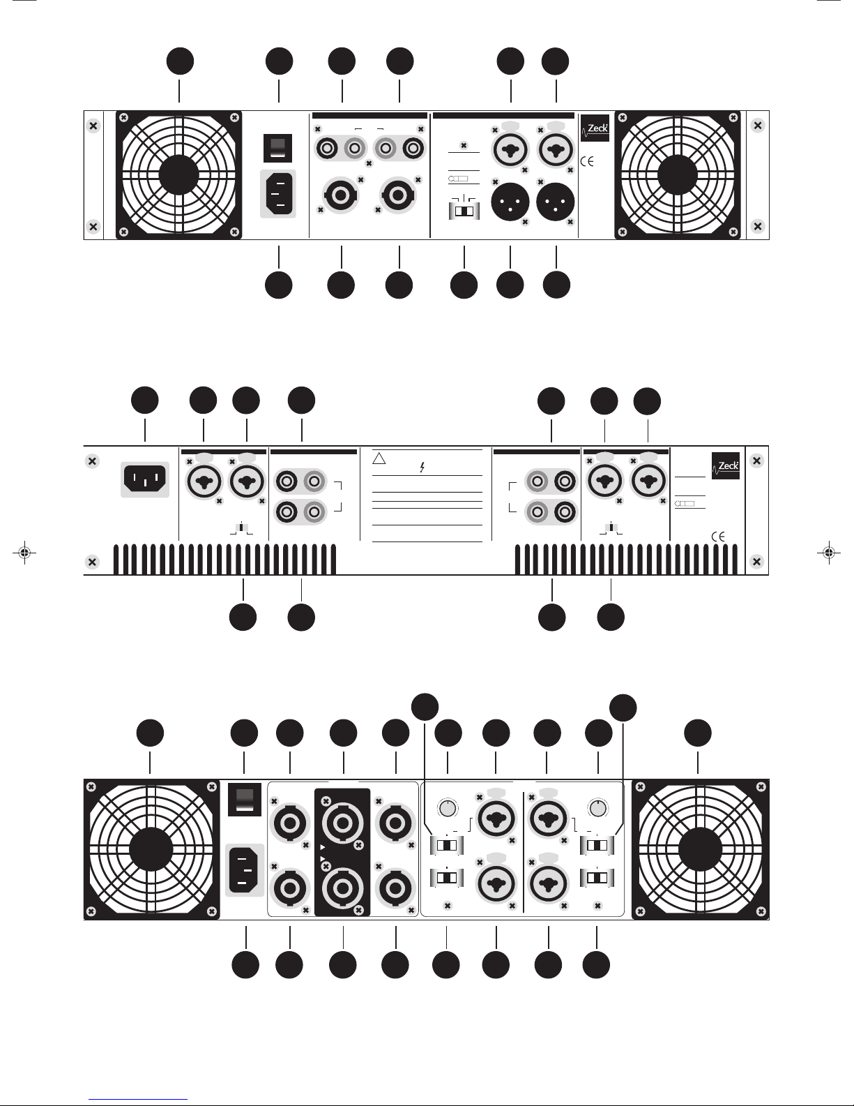
Abb.1: Frontseite der 2-Kanal Modelle
Netzschalter mit Anzeige-LED
1
2
Volumenregler
Für jeden Kanal individuell vorhanden.
3
PROTECT Anzeige
Leuchtet auf, wenn die Schutzschaltung aktiv ist.
4
SIGNAL Anzeige
Leuchtet auf, wenn ein Signal am dazugehörigen
Endstufen-Eingang anliegt.
LIMIT Anzeige
Leuchtet auf, wenn der Limiter aktiv ist um ein Übersteuern der Endstufe zu verhindern.
5
6
BRIDGE MODE Anzeige
Zeigt an, dass mit dem Schalter (9) auf Brückenbetrieb
(Bridge Mode) umgeschaltet wurde.
9
Abb.2: Frontseite der 4-Kanal Modelle
6
CHAMP Series owner‘s manual © Zeck Audio 2000
K000001A01
INPUTOUTPUT
1 2
3 4
STEREO
BRIDGED
1 + 2
PARALLEL
1 / 2
BRIDGED
3 + 4
PARALLEL
3 / 4
INPUT XLR (1/4")
GND = 1 (SLEEVE)
SIG+ = 2 (TIP)
SIG - = 3 (RING)
X-OVER
BYPASS X-OVER x 10
160 Hz
130 Hz
80 Hz
60 Hz
220 Hz
250 Hz
X-OVER FREQUENCY
190 Hz
STEREO
X-OVER INPUT
BYPASS X-OVER x 10
160 Hz
130 Hz
80 Hz
60 Hz
220 Hz
250 Hz
X-OVER FREQUENCY
190 Hz
3+4
1+2
BRIDGE MIN. 8 OHMS
2
4
REFER TO OPERATIONAL MANUAL FOR PROPER BRIDGE MODE OPERATION
1+/1- = SIGNAL +/2+/2- = GND
1+/1- = SIGNAL +/2+/2- = GND
MIN. 4 OHMS
MIN. 4 OHMS
1
3
1+/1- = CH1 (HIGH 1) 1+/1- = CH2 (HIGH 2)
1+/1- = CH 3 (LOW 1)
2+/2- = CH 1 (HIGH 1)
MIN. 4 OHMS
MIN. 4 OHMS
~ AC INPUT
230V 50Hz
PUSH TO RESET
10A/250V
10
A
M
P
INPUT
HIGH HIGH
LOW
1+/1- = CH 4 (LOW 2)
2+/2- = CH 2 (HIGH 2)
LOW
7
8
81111
9 9
101212
13
14
7
Abb.3: Rückseite der 2-Kanal Modelle
(CHAMP 2.250 ohne linken Lüfter)
CH 2
CH 1
CHAMP 4120
2 3 1
3 = SIGNAL -
2 = SIGNAL +
1 = SIGNAL GROUND
INPUT
CH 2
CH 1
CH 4 CH 3
CH 3
OUTPUT OUTPUTINPUT INPUT
THIS APPARATUS MUST BE EARTHED. TO REDUCE THE
RISK OF FIRE OR ELECTRIC SHOCK DO NOT EXPOSE
THIS APPLIANCE TO RAIN OR MOISTURE.
WARNING
NO USER SERVICEABLE PARTS INSIDE.
REFER SERVICING TO QUALIFIED PERSONNEL.
RISQUE DE CHOC ELECTRIQUE. NE PAS OUVRIR.
CAUTION
CAUTION
HAZARDOUS ENERGY!
MAKE PROPER SPEAKER CONNECTIONS.
REFER TO OPERATING MANUAL.
RISK OF ELECTRIC SHOCK.
DO NOT OPEN !
WARNING!
- USE ONLY "+" SPEAKER TERMINALS
- USE ONLY CH 1 INPUT.
BRIDGED MODE:
AVIS
!
STEREO
MIN. 4 OHMS
MIN. 4 OHMS
MIN. 8 OHMS
BRIDGED
MIN. 8 OHMS
BRIDGED
BRIDGED PARALLEL
STEREO
BRIDGED PARALLEL
MIN. 4 OHMS
CH 4
- +
--+
+
-
+
MIN. 4 OHMS
8
8
11
8
8
11
14
1010
Abb.4: Rückseite CHAMP 4.120
7
11
11
8812
12
13
12 15 12
15
10 10
16
17
16
17
8 8
Abb.5: Rückseite CHAMP 4.250X
14
BRIDGED
STEREO
2 3 1
3 = SIGNAL -
2 = SIGNAL +
1 = SIGNAL GROUND
INPUT
SPEAKER OUTPUT MODE SWITCH PARALLEL OUTPUT
CH 1
CH 1CH 2
CH 2
- -+ +
PARALLEL
~ AC INPUT
MAINS FUSE
PUSH TO RESET
10
A
M
P
CHAMP 2350
MIN. 4 OHMS
BRIDGED
MIN.8 OHMS
MIN. 4 OHMS
OUTPUT INPUT
 Loading...