

Zeck Audio CCR24 EQ Owner's Manual
Beschreibung
Die CCR 24 EQ Karte ist ein Einsteckmodul für die Frequenzweiche
CCR 24 von Zeck.
Die Kar te ist mit hochwertigen Operationsverstärkern bestückt und
arbeitet extrem rauscharm. Die EQ-Kurve kann vom Benutzer durch
einfaches Aufstecken der Widerstände und Kondensatoren frei eingestellt werden. Lötarbeiten sind hierfür nicht erforderlich.
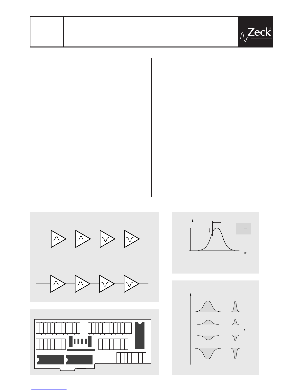
Die 8 vorhandenen Filter sind als Bandlter ausgelegt. Filter 1-4
sind dem linken Kanal zugeordnet, Filter 5- 8 dem rechten Kanal.
Die ersten zwei Filter in jedem Kanal (1,2,5,6) sind als Bandpässe
ausgelegt, die übrigen zwei Filter in jedem Kanal (3,4,7,8) als Bandsperren. Alle vier Filter eines Kanals sind in Reihe geschaltet.
Die Filter-Parameter - Mittenfrequenz (f), Q-Faktor und Gain
(Anhebung/Absenkung) - können unabhängig voneinander berechnet und eingestellt werden. Damit kann für jedes angeschlossene
PA-System eine geeignete EQ-Kur ve eingestellt werden. Im
standardmäßigen Stereobetrieb müssen die zwei Filter der Paare
1/5, 2/6, 3/7, 4/8 jeweils gleich bestückt werden.
Nach dem Einbau in die CCR 24 Frequenzweiche, ist die EQ-Karte
schaltungstechnisch vor der Frequenzweiche angeordnet. Dadurch
arbeiten die Filter der EQ-Karte im vollen Frequenzbereich und
beeinträchtigen darüberhinaus nicht die Phasentreue der CCR 24
Frequenzweiche.
Equalizer-Einbaukarte für CCR 24 Frequenzweiche
Einbau- und Programmieranleitung
Add-on EQ card for CCR 24 crossover
Instructions for installation and programming
CCR 24
EQ
Description
The CCR 24 EQ CARD is a plug-in module for the Zeck CCR 24
three-way stereo crossover.
The module features high-performance operational ampliers and
ultra low-noise circuit design. The user can freely determine the
lter curves by adding the required resisitors and capacitors to the
blank lter circuits. The components are simply plugged into IC
sockets, no soldering whatsoever is required.
The eight lter circuits are designed to produce bell-type EQ curves.
Filters 1- 4 are assigned to the left channel, lters 5-8 to the right
channel. The rst two lters in each channel (1,2,5,6) provide a
bandpass function, the remaining two lters provide a band-rejection function. All four lters of a channel are wired in series.
The lter parameters - center frequency (f), Q-factor and gain
(boost/attenuation) - can be freely determined for exact equalization
of the connected PA system. For standard stereo operation, the two
lters of each pair 1/5, 2/6, 3/7, 4/8 have to be equipped with identical components.
When installed into the CCR 24 crossover unit, the EQ card is
located before the crossover circuits in the signal path, allowing the
EQ card to work throughout the entire audio spectrum without causing phase distortion.
Zuordnung der Widerstände und Kondensatoren
Jedes Filter besteht aus 3 Widerständen und 2 Kondensatoren. Um
ein Filter zu deaktivieren, muss für den jeweils ersten Widerstand
(R001, R004 usw.) eine Drahtbrücke eingesetzt werden. Die anderen Bauteile dieses Filters bleiben unbestückt.
Location of resistors and capacitors
Each lter consists of 3 resistors and 2 capacitors. A lter is
bypassed by installing a jumper wire instead of the rst resistor
(R001, R004 etc.) and leaving out the remaining components of this
lter.
K000002A01
1
CCR24 EQ owner‘s manual © Zeck Audio 20 00
R001
R002
R003
C01
C02
R004
R005
R006
C03
C04
R007
R008
R009
C05
C06
R010
R011
R012
C07
C08
R101
R102
R103
C11
C12
R104
R105
R106
C13
C14
R107
R108
R109
C15
C16
R110
R111
R112
C17
C18
LINKS
LEFT
FILTER #1 FILTER #2 FILTER #3 FILTER #4
RECHTS
RIGHT
FILTER #5 FILTER #6 FILTER #7 FILTER #8
LED
GND
+UB
-UB
1 IN
1 OUT
2 IN
2 OUT
R 001
R 002
R 003
R 004
R 005
R 006
R 007
R 008
R 009
R 010
R 011
R 012
C 01
C 02
C 03
C 04
C 05
C 06
C 07
C 08
C 11
C 12
C 13
C 14
C 15
C 16
C 17
C 18
R 101
R 102
R 103
R 104
R 105
R 106
R 107
R 108
R 109
R 110
R 111
R 112
Bestückungsplan / component layout
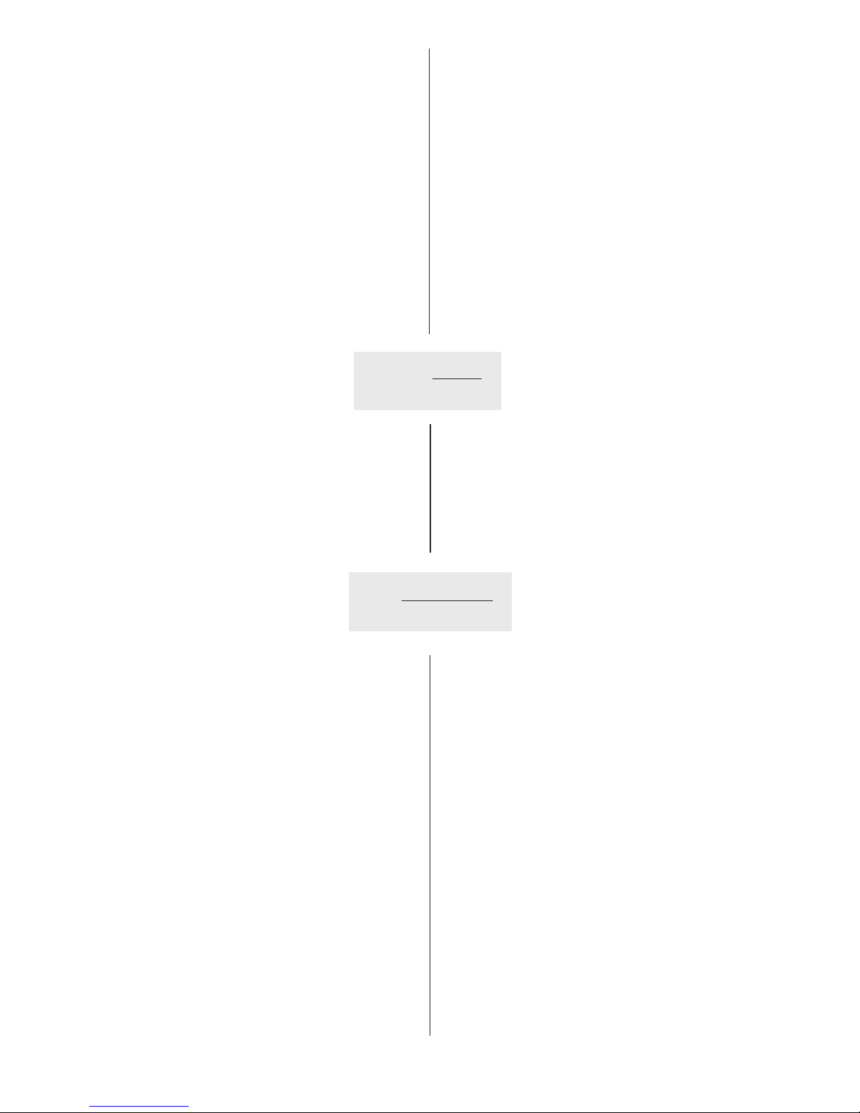
Hz
dB
Gain
B
Mittenfrequenz
f =
center frequency
Bandbreite
B =
bandwidth
Güte
Q =
selectivity
0dB
3dB
f
f
Q =
B
Q
Gain [dB]
Bandpass
Bandsperre
band rejection
positivenegative
Dimensionierung der Bauteile
Die Widerstände und Kondensatoren, die zur Realisierung einer
bestimmten Filtercharakteristik auf die Karte einzustecken sind,
können auf 3 Arten bestimmt werden:
a) Mit der Tabelle auf Seite 4
Hierzu wird ein Taschenrechner benötigt.
1. Wählen sie die gewünschte Kombination von Gain/Q-Faktor
aus den ersten beiden Spalten der Tabelle aus. Die Werte in
der Tabelle gelten für Bandpässe und Bandsperren. Für Bandsperren (Filter 3,4,7 und 8) sind die Gain-Werte als negative Zahlen
(Abschwächung) zu interpretieren.
2. Die drei Zeilen für die Widerstandswerte in der Tabelle geben die
Werte für den jeweils ersten, zweiten und dritten Widerstand des
betreffenden Filter an (z.B. R104, R105 und R106). Die Werte gelten
für eine Mittenfrequenz von 1000 Hz und für Kondensatorwerte von
22 nF und müssen daher umgerechnet werden. Fahren sie fort mit
3a oder 3b.
3a. Sie können die Widerstandswer te aus der Tabelle benutzen und
die neuen Kondensatorwerte für ihre eigene Mittenfrequenz (f) mit
folgender Formel berechnen:
Dimensioning of components
The resistors and capacitors that have to be installed for a certain
EQ curve can be determined with 3 methods:
a) Using the lookup table on page 4
You need a pocket calculator for this method.
1. Select your desired Gain/Q-factor combination from the rst two
columns. The gures in the table apply to bandpass lters and to
band-rejection lters. If you are using one of the band-rejection lters (lters 3,4,7 and 8), the gain gure must be interpreted as a
negative value (attenuation).
2. The 3 columns for the resistor values give you required resistor
values for the rst, second and third resistor of the lter (e.g. R104,
R105 and R106). The resistor values are for a center frequency of
1000 Hz and for capacitor values of 22 nF and therefore have to be
converted to your specications. Continue with 3a or 3b.
3a. You can use the listed values for the resistors and calculate the
new capacitor values C for your specied center frequency f using
the following formula:
22000
C (nF) =
f
f • R • C (nF)
R‘ =
22000
CCR24 EQ owner‘s manual © Zeck Audio 20 00
K000002A01
2
Beispiel: Ziel ist eine Bandsperre für den linken und rechten Kanal mit
2000 Hz Mittenfrequenz, 12 dB Abschwächung (Gain) und einem Q-Faktor
von 4. Wir wollen hierfür das Filterpaar 3 / 7 benutzen. Die Tabelle gibt
für R007 / R107 einen Widerstand von 57875 Ω (56 kΩ) vor, für R008 / R108
einen Wert von 997 Ω (1 kΩ ) und für R 009 / R 109 einen Wert von 9707 Ω
(10 kΩ). Die Kondensatoren C05 / C15 und C06 / C16 müssen nach obenste-
hender Formel den Wer t von 22000 / 20 00 = 11 nF (10 nF) bekommen.
3b. Bei der folgenden Formal kann man einen beliebigen Wert
C für die Kondensatoren vorgeben und neue Werte R‘ für die
Widerstände berechnen:
Example: We want a band-rejection lter for the lef t and right channel at
2000 Hz center frequency with 12 dB attenuation and a Q -factor of 4. For
this purpose, we will use the lter pair 3 / 7. The table species for resistors
R007 / R107 a value of 57875 ohms (use 56 kohms), for resistors R008 / R108
a value of 997 ohms (use 1 kohm) and for R009 / R109 a value of 9707 ohms
(use 10 kohms). The formula above yields a value of 22000 / 2000 = 11 nF
(use 10 nF) for capacitors C05 / C15 and C06 / C16.
3b.The following formula allows to arbitrarily choose a value C for
the capacitors and calculate new resistor values R’:
Beispiel: Für das gleiche Filter wie oben, aber mit 15 nF-Kondensatoren
bekommt man für R 0 07 / R 107 :
R007‘ / R008 ‘ = 2000 • 57875 • 15 / 22000 = 78920 Ω (82 kΩ). Die Widerstände
R008 / R108 und R00 9 / R109 werden entsprechend neu berechnet.
b) Mit dem Microsoft Excel® Spreadsheet
1. Microsoft Excel® Version 5.0 oder höher ist erforderlich.
2. Starten sie Excel® und öf fnen sie das ccrlt.xls Dokument von
der 1/4” Diskette. Mit der angezeigten Tabelle können sie:
3a. Filter-Parameter (Mittenfrequenz, Q- Faktor, Gain) und Kondensatorwerte eingeben. Excel® berechnet die erforderlichen Werte
für die Widerstände.
oder
3b. Werte für Kondensatoren und Widerstände eingeben. Excel®
berechnet die resultierenden Filter-Parameters.
c) Mit der ccrlt software
1. Diese Software benötigt einen PC mit Windows 95 oder höher.
2. Zur Installation, führen sie setup.exe von der 1/4” Diskette aus.
3. Im Fenster Filter-Conguration können sie die gewünschten
Werte für Mittenfrequenz, Q-Faktor und Gain für jedes Filter 1-4
einstellen (Filter 5-8 verhalten sich entsprechend). Jede Eingabe
muss mit der Return-Taste abgeschlossen werden. Filter 1 (5)
und 2 (6) sind Bandpässe und erlauben nur positive Gain-Werte
(Verstärkung), Filter 3 (7) und 4 (8) sind Bandsperren und erlauben
nur negative Gain-Werte (Abschwächung).
Example: For the same lter as above, but with 15 nF capacitors, you get for
R007 / R107 :
R007‘ / R008 ‘ = 2000 • 57875 • 15 / 22000 = 78920 ohms (use 82 kohms).
The remaining resistors R008 / R108 and R009 / R109 must be re-calculated
accordingly.
b) Using the Microsoft Excel® spreadsheet
1. Microsoft Excel® version 5.0 or higher is required.
2. Launch Excel® and open the ccr lt.xls le from the 1/4” disk.
The spreadsheet allows to:
3a. Enter the lter parameters (center frequency, Q-factor, gain) and
value for the capacitors. Excel® will calculate the required resitor
values.
or
3b. Enter the values for capacitors and resistors. Excel® will calculate the resulting lter parameters
c) Using the ccrlt software
1. The software requires a PC with Windows 95 or higher.
2. Install the program by starting the setup.exe le from the 1/4”
disk.
3. Use the Filter-Conguration window to enter the desired values
for center frequency, Q-factor and gain for each individual lter 1-4
(lters 5 -8 behave accordingly). You must conrm every value with
the Return button. As lters 1 (5) and 2 (6) are bandpass lters, they
provide only positive gain (boost). Filters 3 (7) and 4 (8) are bandrejection lters and allow only for negative gain (attenuation).
 Loading...