


zebris Medical GmbH
www.zebris.de
Text-Release: 19/01/2016
Specifications
Operating Instructions
and

zebris Medical GmbH
FDM Technical Data and Operating Instructions
Page 2/54
Inhalt
1 USER NOTES ................................................................................................................................. 4
1.1 INTRODUCTION .............................................................................................................................. 4
1.2 MANUFACTURER AND SALES .......................................................................................................... 5
1.3 LAYOUT OF THE USER MANUAL FOR THE FDM SYSTEM .................................................................... 5
1.4 CONVENTIONS AND SYMBOLS USED ............................................................................................... 6
2 SCOPE AND SECURITY ................................................................................................................ 7
2.1 INTENDED USE .............................................................................................................................. 7
2.1.1 Indications ................................................................................................................................... 7
2.1.2 Contraindications ........................................................................................................................ 7
2.2 SAFETY ......................................................................................................................................... 8
2.2.1 Environmental conditions ............................................................................................................ 8
2.2.2 Storage and Transport ................................................................................................................ 8
2.2.3 User Obligations .......................................................................................................................... 9
2.2.4 General safety instructions ....................................................................................................... 10
3 PRODUCT DESCRIPTION ........................................................................................................... 11
3.1 SYSTEM COMPONENTS ................................................................................................................ 11
3.2 TECHNICAL SPECIFICATIONS FDM MEASURING SYSTEMS ............................................................... 11
3.2.1 FDM Sensor .............................................................................................................................. 11
3.2.2 FDM platforms for stance and roll over analysis ....................................................................... 12
3.2.3 FDM system for jump analysis .................................................................................................. 13
3.2.4 FDM system for stance and gait analysis ................................................................................. 14
3.2.5 FDM platforms for gait training and rehabilitation applications ................................................. 16
3.3 MEASURING PRINCIPLE ................................................................................................................ 17
3.4 CONTROLS AND CONNECTORS ..................................................................................................... 18
3.5 STATUS INDICATOR LED .............................................................................................................. 18
3.6 ZEBRIS SYNC ............................................................................................................................. 19
3.6.1 Synchronization input (SYNC-IN) ............................................................................................. 20
3.6.2 Synchronization output (SYNC-OUT) ....................................................................................... 21
3.6.3 Synchronizing the FDM Platform with video data (Sync Audio) ............................................... 22
3.6.4 Infrared synchronization with zebris DAB- Bluetooth (EMG) .................................................... 23
3.6.5 Combine two FDM platforms oft he same type ......................................................................... 24
3.7 SPARE PARTS FDM SYSTEM ....................................................................................................... 25
3.8 ACCESSORIES FDM MEASURING SYSTEM .................................................................................... 25
4 VIDEO-MODULE........................................................................................................................... 28
4.1 SYNCCAM ................................................................................................................................. 28
4.2 SYNCLIGHTCAM ........................................................................................................................ 29
4.3 LED VIDEO LIGHTS (SYNCLIGHT / SYNCLIGHT PLUS) ................................................................. 32
4.3.1 SYNCLight ................................................................................................................................ 33
4.3.2 SYNCLight plus ......................................................................................................................... 34
4.3.3 Power Supply Unit SYNCLights ................................................................................................ 35
5 OPERATION OF THE FDM SYSTEM .......................................................................................... 37
5.1 SET UP THE MEASURING SYSTEM ................................................................................................. 37
5.2 HOW TO SWITCH THE PLATFORM ON/OFF ..................................................................................... 37
5.3 ANSCHLUSS DES MESSSYSTEMS AN DAS VERSORGUNGSNETZ ....................................................... 38
5.4 COMPUTER REQUIREMENTS ......................................................................................................... 40
5.5 INSTALLING THE ZEBRIS FDM SOFTWARE ..................................................................................... 40
5.6 CLOSING THE SAFETY LOCK OF THE PLUG TRAY ............................................................................. 41
5.7 SETTING THE SYSTEM OUT OF OPERATION .................................................................................... 41
5.8 RECOMMENDATIONS FOR RECORDING DATA .................................................................................. 42
5.8.1 Walking range ........................................................................................................................... 42
5.8.2 Data recording ........................................................................................................................... 42
5.8.3 Gait velocity ............................................................................................................................... 42
5.8.4 Posture ...................................................................................................................................... 42
5.8.5 Acrosclerosis ............................................................................................................................. 42

zebris Medical GmbH
FDM Technical Data and Operating Instructions
Page 3/54
6 CONTROL MEASURES, PREPARATION, DISPOSAL .............................................................. 43
6.1 MANDATORY PERIODIC INSPECTIONS AND STK ............................................................................. 43
6.2 CHECKING THE FDM SENSOR ...................................................................................................... 44
6.2.1 Control measures ...................................................................................................................... 44
6.2.2 Calibration measures ................................................................................................................ 44
6.3 TROUBLESHOOTING ..................................................................................................................... 45
6.4 CLEANING AND DISINFECTION ....................................................................................................... 46
6.4.1 Cleaning .................................................................................................................................... 46
6.4.2 Manuelle Desinfektion ............................................................................................................... 46
6.5 DISPOSAL ................................................................................................................................... 47
6.5.1 Packaging ................................................................................................................................. 47
6.5.2 Disposal of electronics .............................................................................................................. 47
7 SAFETY STANDARDS AND SYSTEM CLASSIFICATION ........................................................ 48
7.1 CLASSIFICATION ACC. TO ANNEX IX OF DIRECTIVE 93/42/EEC ...................................................... 48
7.2 SAFETY OF MEDICAL ELECTRICAL DEVICES .................................................................................... 48
7.2.1 Connecting the FDM-System to other electrical devices .......................................................... 48
7.2.2 Vicinity of the patient / test person ............................................................................................ 49
7.2.3 Use of multiple sockets ............................................................................................................. 50
7.3 ELECTROMAGNETIC COMPATIBILITY GUIDELINE & MANUFACTURER DECLARATION .......................... 51
7.4 DECLARATION OF CONFORMITY MEDICAL PLATFORMS .................................................................... 54

zebris Medical GmbH
FDM Technical Data and Operating Instructions
Page 4/54
1 User Notes
1.1 Introduction
Welcome to the User Manual for the zebris FDM measuring system.
This User Manual provides a basic understanding for operating the FDM measuring system.
It provides essential information for the set up of the system and suggests basic principles
for preparing the measuring procedure and data recording.
zebris Medical GmbH does not assume any liability for injury to personnel or patients, nor
damage to the device caused by improper use of the FDM measuring system for gait and
stance analysis.
All data about the measuring system FDM within this user manual has been collected, compiled and checked with the greatest possible care. Nevertheless a User Manual may remain
subject to printing errors, faults and changes. Therefore we should like to point out that
zebris Medical GmbH neither guarantees nor holds the legal responsibility or any liability
whatsoever for consequences occurring due to incorrect data.
Should you become aware of any errors when using this User Manual, or should you find
details that do not conform with your device, please kindly inform us. We shall then correct
any possible errors as quickly as possible.
In the interests of continuous product development, the manufacturer reserves the right to
carry out improvements to this User Manual and the product described therein at any time
and without any further obligation.
Registered trade marks
Several brand names are referred within this User Manual. All these product names are
used only for clarity’s sake or for editorial reasons and are trademarks belonging to the
respective companies. When using the brand names, the trade marks them and also the
rights of the respective proprietors remain protected.
The name zebris is a registered trade mark and FDM identifies a product of the company,
zebris Medical GmbH.
Copyright
This document and extracts taken from it may on no account be duplicated without the ex-
plicit consent of zebris Medical GmbH. The content of this document may on no account be
used for purposes that have not undergone approval by zebris Medical GmbH. Any infringement of the copyright is a punishable offence.
© Copyright zebris Medical GmbH
All rights reserved.

zebris Medical GmbH
FDM Technical Data and Operating Instructions
Page 5/54
1.2 Manufacturer and sales
NOTE
Please closely observe the user manuals with initial operation,
use or maintenance as well as transport of the FDM measuring
system.
WARNING
The exact adherence to the instructions in all sections of the operating
Instructions for the measuring system is a precondition for its intended
use.
zebris Medical GmbH
Am Galgenbühl 14 Telephone +49 (0)7562 9726 0
D-88316 Isny im Allgäu Telefax +49 (0)7562 9726 50
Deutschland
Internet: www.zebris.de E-Mail info@zebris.de
1.3 Layout of the user manual for the FDM System
The measuring system FDM consists of the force distribution measuring sensor technology
as well as the corresponding application software including a PC.
Therefore, the user manual of the FDM measuring system consists of several parts:
1. FDM technical specifications and user manual
2. zebris FDM user manual of the application software
3. User manual of the accessories, like e.g. projector or PC
The section FDM technical specifications and user manual primarily contains information on
technical data and the operation of the FDM force distribution measuring sensor technology
as well as on their safe operation.

zebris Medical GmbH
FDM Technical Data and Operating Instructions
Page 6/54
1.4 Conventions and Symbols Used
The green markings in the margin of the User Manual denote
new information about the product safety.
“WARNING” symbols indicate a potential hazard to the health
and safety of the users and/or patients. The warnings describe
the risks involved and those can be avoided.
“NOTE” symbols indicate a potential risk which could lead to
damaging of the device. These NOTE symbols describe the risks
involved and how those can be avoided.
The CE mark on the type plate confirms the conformity of the
measuring system with the Directive 73/23/EEC and Directive
89/366/EEC (Low Voltage Directive and EMC Directive).
The CE mark with reference number 0535 of notified body BSI
(formerly EUROCAT) on the type plate confirms the conformity
of the system with the Directive 93/42/EEC for Medical Devices.
Symbol for manufacturer and date of production.
Device of type BF according to DIN EN 60601-1
Symbol for the connection of the external power supply unit
(DC voltage 15-20V with indicated polarity)
USB-Interface
The symbol indicates that in accordance with the Directive
2002/96/EEC (Waste Electronic and Electrical Equipment Directive) and national laws, a product must not be disposed of in
the household waste, and that within Europe it has to be disposed of in a special way.
Carefully read the accompanying documentation, particularly all
information concerning product safety
REF
Item number of the measuring system / accessories
SN
Serial number of the measuring system

zebris Medical GmbH
FDM Technical Data and Operating Instructions
Page 7/54
2 Scope and security
2.1 Intended Use
Main function of the force distribution measurement system FDM is the spatially resolved
force distribution measurement under human feet for the analysis of static and dynamic
strains as well as the individual gait parameters.
Operation as well as data evaluation and storage are software-aided by using a computer.
The measuring systems are suitable for the use with patients that are mentally capable of
following the operator’s instructions without limitations in the period of application.
The patient’s weight is limited by the maximum permissible weight of the treadmill. For the
application of the FDM-T with children or patients with severe movement disorders, a fall
stop safety is strongly recommended.
Professional facilities (medical practices, clinics, scientific institutions, rehabilitation centres,
and orthopaedic specialist shops) are specified as application environment.
The application and operation of the system may only be carried out by thoroughly trained
qualified personnel such as clinical doctors, physiotherapists, orthopedics which posses the
ability to evaluate the output data in medical aspects as a aid for the diagnosis, treatment or
patient care and taking into account the clinical history of the patient in the context of other
diagnostic tests.
2.1.1 Indications
Stance and gait analysis of the “normal” as well as the pathological stance and gait.
Diagnosis support with foot malpositions and foot corrections
Diagnosis support and therapy of imbalances / incorrect gait pattern
Detection of inappropriate mechanical stress and overstraining for the prevention of phys-
ical problems and for rehabilitation with disabilities after injury, accidents or surgeries.
Support with the development, adjustment and verification of orthopaedic aids for the
individual patient care
Balance analysis and balance training
Gait training in combination with dynamic visual stimulation (cueing) and feedback train-
ing as therapy/rehabilitation measures after a surgery, stroke, with the Parkinson’s dis-
ease as well as other neurologic and orthopaedic disorders
Success control of therapy/rehabilitation measures
2.1.2 Contraindications
The FDM system must not be applied for a barefoot measurement with patients having
open wounds and/or infections on the feet.

zebris Medical GmbH
FDM Technical Data and Operating Instructions
Page 8/54
2.2 Safety
WARNING
FDM systems must NOT be operated in wet zones, wet rooms (swimming pools, saunas) or climatic chambers.
Direct contact with liquids must always be avoided, as the measuring
system is not protected against the entering of liquids. Liquids entering the device can cause fire, electrical shock or other severe accidents.
The FDM system is NOT specified for the operation in vacuum, hyperbaric or altitude chambers.
The measuring systems are not intended for operation in potentially
explosive atmospheres of medically used rooms or oxygen-enriched
atmospheres.
The devices must not be operated in proximity to e.g. engines or
transformers with a high connected load as well as mains current
lines, as electrical or magnetic interference fields can falsify correct
measurements resp. turn them impossible.
2.2.1 Environmental conditions
FDM Measuring Systems are suitable for application in dry interiors with level ground such
as those in hospitals, doctors' surgeries and laboratories.
Temperature range 10°C to 40°C
Relative humidity 30% to 70%
2.2.2 Storage and Transport
Storage and transport of the measuring system are only to be effected in the original packaging provided by zebris.
Storage temperature -20°C to +70°C
Relative humidity 5% to 90%
Air pressure 700 hPa to 1060 hPa

zebris Medical GmbH
FDM Technical Data and Operating Instructions
Page 9/54
2.2.3 User Obligations
The relevant, general guidelines and/or national laws, national regulations and technical
rules for the commissioning and the operation of medical products must be applied and
fulfilled corresponding to the indicated purpose of the zebris product. In Germany, operators, device in-charge persons and users are obliged to operate their devices in consideration of the MPG-regulations.
Users are obliged to:
observe all safety guidelines of the user manual.
carry out any inspection and maintenance works on a regular basis as stipulated in
the user manual.
only use work equipment that is free of defects.
check the functional safety and the proper condition of the device before operating.
make all user manuals that are included in delivery and part of the measuring system
accessible to all users at all times and keep the manuals in close proximity of the
measuring system.
protect him-/herself, the patient or third parties against dangers.
avoid a contamination through the product.
When using the system, national legal regulations must be observed, in particular:
the valid industrial safety regulations.
the valid accident prevention.
For the safety, reliability and performance of the components delivered by zebris, respon-
sibility is assumed, if:
assembly, extensions, re-settings, changes or repairs were carried out through zebris
or third parties authorised by zebris, trained technicians or employees of authorised
dealers. Storage and transport are only to be effected in the original packaging delivered by the manufacturer.
the device is operated in accordance with the user manual.
in case of repair, the regulations of the VDE 0751-1 “Recurrent test and test before
commissioning of medical electrical equipment – general regulations” are fully complied with.
the components of information technology provided by the operator correspond to the
technical requirements of hard and software included in this user manual and also
were installed and set up according to the relevant descriptions in this user manual.
the set-up room corresponds to the given environmental conditions of the measuring
the FDM system including accessories is connected to the mains socket with a pro-
exclusively the software provided by zebris as well as the components and accessory
system and the valid installation regulations.
tective grounding conductor and is operated with the correct mains voltage.
parts listed in this user manual are used together with the system.

zebris Medical GmbH
FDM Technical Data and Operating Instructions
Page 10/54
2.2.4 General safety instructions
The application and operation of the system and also the evaluation of the measuring
data and their interpretation may only be carried out by trained qualified personnel. The
manufacturer assumes no liability for any injury to persons, damage to property, or loss
of data due to improper use of the software, the device or its component parts.
The patients’ data and measuring data may only be copied, moved, or deleted using the
data-base function provided by the zebris application programs. In the case of data being
changed intentionally without using the database functions, the user alone bears the full
risks involved.
Measurement and analysis results should always be interpreted in the light of the clinical
history of the patient and in the context of other diagnostic tests by a trained person
proven and tested for their relevance.
Should any measures for treatment be taken on the basis of the measuring results, the
measuring system may only be implemented as a supplementary means for evaluation
by an expert. On no account can, or may invasive measures, or measures endangering
the patient be carried out solely on the basis of the measuring results without further
verification of the measuring data by additional methods.
Should there be any detectable damage to the device or component parts, they should
be returned to the manufacturer for a safety check. It is not permissible to continue using
the device or its component parts, as severe damage and serious injuries - even lethal
injuries - may result. The manufacturer or authorized sales partner must always be contacted in all cases of fault or doubt.
If any fluids should penetrate the device, it is mandatory for the device to undergo a tech-
nical, safety test. Damaged plug connections and leads are to be replaced by an authorized service technician. The device must be put out of operation immediately, marked as
"Not working“ and prevented from being used by removing the mains cable.
The measuring system must be checked at regular intervals to make sure it is functioning
properly. More details on this can be found in the section, "Maintenance of the Device" in
this User Manual
Be sure that all the mains and connection cables are laid safely and that they are pro-
tected against stepping on, so that nobody can trip over them. Check all the cables and
the connection plug regularly for any damage. Damaged power Supplys and cables have
to be replaced before further operation
Never try to service the measuring system in any other way as described in the provided
user manual. When removing the covers, you may expose yourself to lethal voltages or
other risks.
We also point out that if any changes are made to this certified device or its accessories
without the prior written consent of zebris, your legal right to operate the device will be
nullified.

zebris Medical GmbH
FDM Technical Data and Operating Instructions
Page 11/54
3 Product description
3.1 System components
In its basic configuration the FDM measuring system consists oft he following components:
FDM platform
External power supply unit
USB cable (Type A-A, 3.5 m length)
zebris application software zebris FDM
IBM® compatible computer or notebook
User Manual for platform and software, equipment and zebris FDM Software
3.2 Technical specifications FDM measuring systems
3.2.1 FDM Sensor
The sensors of the different FDM system only vary in size of the measuring area, the number
of single sensors included in the sensor module and the supported sampling frequency. All
other technical data is identical:
Interfaces USB
Synchronization input/output
Video synchronization
Infrared synchronization
Connection Interface box on bottom of housing frame
Measuring principle capacitive force measurement
Operating voltage 16-18V DC
Power consumption max. 60W (depends on type)
Power supply via external power supply unit 100-240V AC / 50-60Hz
Measuring Range 1-120N/cm2
Accuracy of the calibrated measuring range (1-120N/cm2) ±5% (FS)
Mechanical crosstalk -25dB
Pressure threshold 1N/cm²

zebris Medical GmbH
FDM Technical Data and Operating Instructions
Page 12/54
3.2.2 FDM platforms for stance and roll over analysis
Type
FDM-SX
REF.-No.
01243005
Outer dimensions
550 x 400 x 21 mm (L x W x H)
Weight
ca. 4,8 kg
Measuring frequency
120 Hz
Number of sensors
40 x 48 / 1920
Sensor surface
400 x 330 mm (L x W)
Resolution
1/3 “ resp. 1,4 sensors/ cm²
Infrared interface
optional
Type
FDM-S
REF.-No.
01243010
Outer dimensions
690 x 400 x 21 mm (L x W x H)
Weight
ca. 6,5 kg
Measuring frequency
100 Hz / optional 240 Hz
Number of sensors
40 x 64 / 2560
Sensor surface
540 x 330 mm (L x W)
Resolution
1/3 “ resp. 1,4 sensors / cm²
Infrared interface
optional
Connector box
at bottom side
Connector box
at bottom side
zebris Medical GmbH
FDM Technical Data and Operating Instructions
Page 13/54
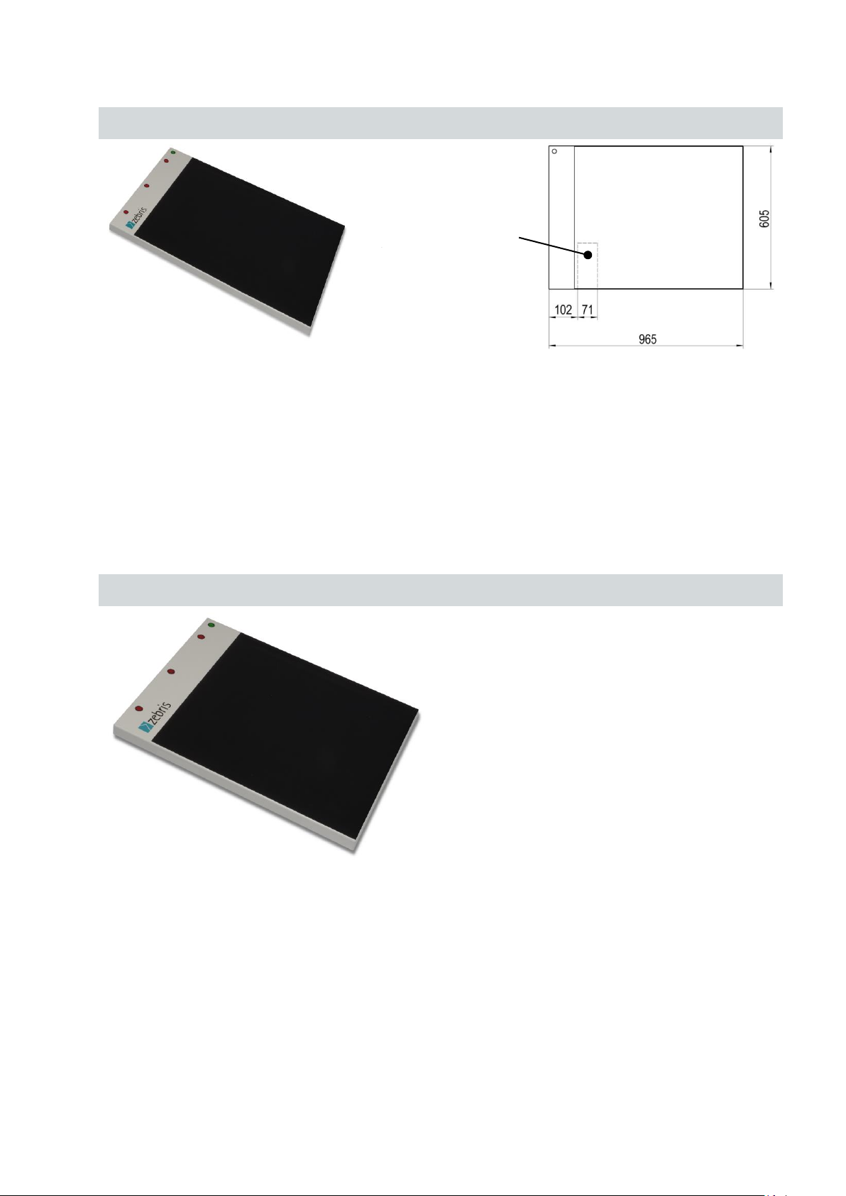
3.2.3 FDM system for jump analysis
Type
FDM-J1.0
REF.-No.
01243200
Outer dimensions
965 x 605 x 21 mm (L x W x H)
Weight
approx.12 kg
Measuring frequency
400 Hz / optional 800 Hz
Number of sensors
60 x 64 / 2560
Sensor surface
810 x 510 mm (L x W)
Resolution
1/2 “ resp. 0.6 sensors / cm²
Infrared interface
integrated
Geben Sie hier eine Formel ein.
Type
FDM-J1.8SQ
REF.-No.
01243210
Outer dimensions
1810 x 1940 x 21 mm (L x W x H)
Weight
approx. 50 kg
Measuring frequency
100 Hz
Number of sensors
96 x 96 / 9216
Sensor surface
1730 x 1730 mm (L x W)
Resolution
3/4 “ approx. 0.3 sensors / cm²
Infrared interface
integrated
Connector box
at bottom side
zebris Medical GmbH
FDM Technical Data and Operating Instructions
Page 14/54
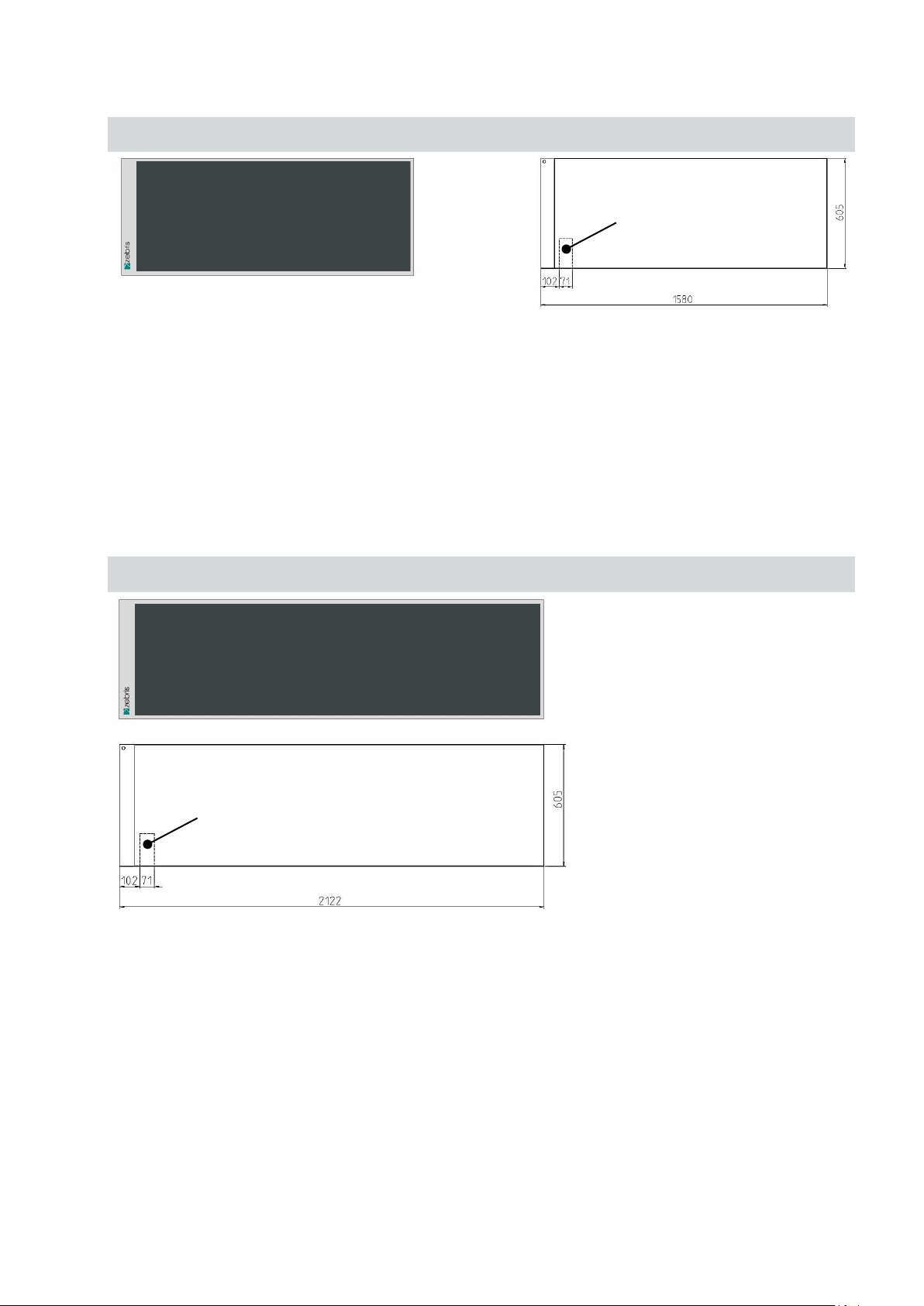
3.2.4 FDM system for stance and gait analysis
Type
FDM-1.5
REF.-No.
01243015
Outer dimensions
1580 x 605 x 21 mm (L x W x H)
Weight
ca. 16,5 kg
Measuring frequency
120 Hz / optional 200 Hz oder 300 Hz
Number of sensors
64 x 176 / 11264
Sensor surface
1440 x 560 mm (L x W)
Resolution
1/3 “ resp. 1,4 sensors / cm²
Infrared interface
integrated
Type
FDM-2
REF.-No.
01243020
Outer dimensions
2122 x 605 x 21 mm (L x W x H)
Weight
approx. 25 kg
Measuring frequency
120 Hz / optional 200 Hz oder 300 Hz
Number of sensors
64 x 240 / 15360
Sensor surface
2030 x 560 mm (L x W)
Resolution
1/3 “ resp. 1,4 sensors / cm²
Infrared interface
integrated
Connector box
at bottom side
Connector box
at bottom side

zebris Medical GmbH
FDM Technical Data and Operating Instructions
Page 15/54
Type
FDM-3
REF.-No.
01243030
Outer dimensions
3070 x 605 x 21 mm (L x W x H)
Weight
approx. 35 kg
Measuring frequency
100 Hz
Number of sensors
64 x 352 / 22528
Sensor surface
2980 x 560 mm (L x W)
Resolution
1/3 “ resp. 1,4 sensors / cm²
Infrared interface
integrated
Connector box
at bottom side

zebris Medical GmbH
FDM Technical Data and Operating Instructions
Page 16/54
3.2.5 FDM platforms for gait training and rehabilitation applications
Type
FDM-1.7
REF.-No.
01243034
Outer dimensions
1820 x 600 x 21 mm (L x W x H)
Weight
approx. 22 kg
Measuring frequency
100 Hz
Number of sensors
44 x 136 / 5984
Sensor surface
1730 x 560 mm (L x W)
Resolution
1/2 “ resp. 0.6 sensors / cm²
Infrared interface
optional
Type
FDM-2.4
REF.-No.
01243035
Outer dimensions
2510 x 600 x 21 mm (L x W x H)
Weight
approx. 31 kg
Measuring frequency
100 Hz
Number of sensors
44 x 190 / 8360
Sensor surface
2410 x 560 mm (L x W)
Resolution
1/2 “ resp. 0.6 sensors / cm²
Infrared interface
optional
Connector box
at bottom side
Connector box
at bottom side
Ready for installation
in h/p/cosmos parawalk

zebris Medical GmbH
FDM Technical Data and Operating Instructions
Page 17/54
3.3 Measuring principle
Kapazitive Meßmatrix
Spaltendekoder
Treiber
Diodenschalter
Schiebe-
register
Diodenschalter
Schiebe-
register
...
Burstgenerator, Ansteuerlogik
Gleichrichter, Verstärker,
8-Bit ADC
Datenbus
Kalibrierdaten
Kalibrier- Flash
RAM
Optokoppler &
Galvanische Trennung mit
Gleichrichter
PC
externes
AC-Netzteil
entspricht
IEC 601
USB
CPU
Programm-
daten
CPU-internes
Flash
Diodenschalter
Schiebe-
register
Diodenschalter
Schiebe-
register
...
The system contains a measuring matrix consisting of capacitive pressure sensors that
are arranged in columns and lines running closely next to each other. For determining the
force distribution over the measuring matrix the capacity proportional to the force exerted
is determined for each individual sensor. To do this, the drive logic generates a number
of sinus burst signals equivalent to the number of columns via the column decoder, and
transmits them to the respective measuring column. The analog signal coupled into the
shift register over the lines is proportional to the pressure-dependent capacity and is
passed on for further processing to the control and signal-processing electronics and
transmitted to the PC from there and shown on the display.
Schematic circuit diagram of the measuring system
 Loading...