

Page 1

zebris Medical GmbH
www.zebris.de
Text-Release: 19/01/2016
Specifications
Operating Instructions
and
Page 2

zebris Medical GmbH
FDM Technical Data and Operating Instructions
Page 2/54
Inhalt
1 USER NOTES ................................................................................................................................. 4
1.1 INTRODUCTION .............................................................................................................................. 4
1.2 MANUFACTURER AND SALES .......................................................................................................... 5
1.3 LAYOUT OF THE USER MANUAL FOR THE FDM SYSTEM .................................................................... 5
1.4 CONVENTIONS AND SYMBOLS USED ............................................................................................... 6
2 SCOPE AND SECURITY ................................................................................................................ 7
2.1 INTENDED USE .............................................................................................................................. 7
2.1.1 Indications ................................................................................................................................... 7
2.1.2 Contraindications ........................................................................................................................ 7
2.2 SAFETY ......................................................................................................................................... 8
2.2.1 Environmental conditions ............................................................................................................ 8
2.2.2 Storage and Transport ................................................................................................................ 8
2.2.3 User Obligations .......................................................................................................................... 9
2.2.4 General safety instructions ....................................................................................................... 10
3 PRODUCT DESCRIPTION ........................................................................................................... 11
3.1 SYSTEM COMPONENTS ................................................................................................................ 11
3.2 TECHNICAL SPECIFICATIONS FDM MEASURING SYSTEMS ............................................................... 11
3.2.1 FDM Sensor .............................................................................................................................. 11
3.2.2 FDM platforms for stance and roll over analysis ....................................................................... 12
3.2.3 FDM system for jump analysis .................................................................................................. 13
3.2.4 FDM system for stance and gait analysis ................................................................................. 14
3.2.5 FDM platforms for gait training and rehabilitation applications ................................................. 16
3.3 MEASURING PRINCIPLE ................................................................................................................ 17
3.4 CONTROLS AND CONNECTORS ..................................................................................................... 18
3.5 STATUS INDICATOR LED .............................................................................................................. 18
3.6 ZEBRIS SYNC ............................................................................................................................. 19
3.6.1 Synchronization input (SYNC-IN) ............................................................................................. 20
3.6.2 Synchronization output (SYNC-OUT) ....................................................................................... 21
3.6.3 Synchronizing the FDM Platform with video data (Sync Audio) ............................................... 22
3.6.4 Infrared synchronization with zebris DAB- Bluetooth (EMG) .................................................... 23
3.6.5 Combine two FDM platforms oft he same type ......................................................................... 24
3.7 SPARE PARTS FDM SYSTEM ....................................................................................................... 25
3.8 ACCESSORIES FDM MEASURING SYSTEM .................................................................................... 25
4 VIDEO-MODULE........................................................................................................................... 28
4.1 SYNCCAM ................................................................................................................................. 28
4.2 SYNCLIGHTCAM ........................................................................................................................ 29
4.3 LED VIDEO LIGHTS (SYNCLIGHT / SYNCLIGHT PLUS) ................................................................. 32
4.3.1 SYNCLight ................................................................................................................................ 33
4.3.2 SYNCLight plus ......................................................................................................................... 34
4.3.3 Power Supply Unit SYNCLights ................................................................................................ 35
5 OPERATION OF THE FDM SYSTEM .......................................................................................... 37
5.1 SET UP THE MEASURING SYSTEM ................................................................................................. 37
5.2 HOW TO SWITCH THE PLATFORM ON/OFF ..................................................................................... 37
5.3 ANSCHLUSS DES MESSSYSTEMS AN DAS VERSORGUNGSNETZ ....................................................... 38
5.4 COMPUTER REQUIREMENTS ......................................................................................................... 40
5.5 INSTALLING THE ZEBRIS FDM SOFTWARE ..................................................................................... 40
5.6 CLOSING THE SAFETY LOCK OF THE PLUG TRAY ............................................................................. 41
5.7 SETTING THE SYSTEM OUT OF OPERATION .................................................................................... 41
5.8 RECOMMENDATIONS FOR RECORDING DATA .................................................................................. 42
5.8.1 Walking range ........................................................................................................................... 42
5.8.2 Data recording ........................................................................................................................... 42
5.8.3 Gait velocity ............................................................................................................................... 42
5.8.4 Posture ...................................................................................................................................... 42
5.8.5 Acrosclerosis ............................................................................................................................. 42
Page 3

zebris Medical GmbH
FDM Technical Data and Operating Instructions
Page 3/54
6 CONTROL MEASURES, PREPARATION, DISPOSAL .............................................................. 43
6.1 MANDATORY PERIODIC INSPECTIONS AND STK ............................................................................. 43
6.2 CHECKING THE FDM SENSOR ...................................................................................................... 44
6.2.1 Control measures ...................................................................................................................... 44
6.2.2 Calibration measures ................................................................................................................ 44
6.3 TROUBLESHOOTING ..................................................................................................................... 45
6.4 CLEANING AND DISINFECTION ....................................................................................................... 46
6.4.1 Cleaning .................................................................................................................................... 46
6.4.2 Manuelle Desinfektion ............................................................................................................... 46
6.5 DISPOSAL ................................................................................................................................... 47
6.5.1 Packaging ................................................................................................................................. 47
6.5.2 Disposal of electronics .............................................................................................................. 47
7 SAFETY STANDARDS AND SYSTEM CLASSIFICATION ........................................................ 48
7.1 CLASSIFICATION ACC. TO ANNEX IX OF DIRECTIVE 93/42/EEC ...................................................... 48
7.2 SAFETY OF MEDICAL ELECTRICAL DEVICES .................................................................................... 48
7.2.1 Connecting the FDM-System to other electrical devices .......................................................... 48
7.2.2 Vicinity of the patient / test person ............................................................................................ 49
7.2.3 Use of multiple sockets ............................................................................................................. 50
7.3 ELECTROMAGNETIC COMPATIBILITY GUIDELINE & MANUFACTURER DECLARATION .......................... 51
7.4 DECLARATION OF CONFORMITY MEDICAL PLATFORMS .................................................................... 54
Page 4

zebris Medical GmbH
FDM Technical Data and Operating Instructions
Page 4/54
1 User Notes
1.1 Introduction
Welcome to the User Manual for the zebris FDM measuring system.
This User Manual provides a basic understanding for operating the FDM measuring system.
It provides essential information for the set up of the system and suggests basic principles
for preparing the measuring procedure and data recording.
zebris Medical GmbH does not assume any liability for injury to personnel or patients, nor
damage to the device caused by improper use of the FDM measuring system for gait and
stance analysis.
All data about the measuring system FDM within this user manual has been collected, compiled and checked with the greatest possible care. Nevertheless a User Manual may remain
subject to printing errors, faults and changes. Therefore we should like to point out that
zebris Medical GmbH neither guarantees nor holds the legal responsibility or any liability
whatsoever for consequences occurring due to incorrect data.
Should you become aware of any errors when using this User Manual, or should you find
details that do not conform with your device, please kindly inform us. We shall then correct
any possible errors as quickly as possible.
In the interests of continuous product development, the manufacturer reserves the right to
carry out improvements to this User Manual and the product described therein at any time
and without any further obligation.
Registered trade marks
Several brand names are referred within this User Manual. All these product names are
used only for clarity’s sake or for editorial reasons and are trademarks belonging to the
respective companies. When using the brand names, the trade marks them and also the
rights of the respective proprietors remain protected.
The name zebris is a registered trade mark and FDM identifies a product of the company,
zebris Medical GmbH.
Copyright
This document and extracts taken from it may on no account be duplicated without the ex-
plicit consent of zebris Medical GmbH. The content of this document may on no account be
used for purposes that have not undergone approval by zebris Medical GmbH. Any infringement of the copyright is a punishable offence.
© Copyright zebris Medical GmbH
All rights reserved.
Page 5

zebris Medical GmbH
FDM Technical Data and Operating Instructions
Page 5/54
1.2 Manufacturer and sales
NOTE
Please closely observe the user manuals with initial operation,
use or maintenance as well as transport of the FDM measuring
system.
WARNING
The exact adherence to the instructions in all sections of the operating
Instructions for the measuring system is a precondition for its intended
use.
zebris Medical GmbH
Am Galgenbühl 14 Telephone +49 (0)7562 9726 0
D-88316 Isny im Allgäu Telefax +49 (0)7562 9726 50
Deutschland
Internet: www.zebris.de E-Mail info@zebris.de
1.3 Layout of the user manual for the FDM System
The measuring system FDM consists of the force distribution measuring sensor technology
as well as the corresponding application software including a PC.
Therefore, the user manual of the FDM measuring system consists of several parts:
1. FDM technical specifications and user manual
2. zebris FDM user manual of the application software
3. User manual of the accessories, like e.g. projector or PC
The section FDM technical specifications and user manual primarily contains information on
technical data and the operation of the FDM force distribution measuring sensor technology
as well as on their safe operation.
Page 6

zebris Medical GmbH
FDM Technical Data and Operating Instructions
Page 6/54
1.4 Conventions and Symbols Used
The green markings in the margin of the User Manual denote
new information about the product safety.
“WARNING” symbols indicate a potential hazard to the health
and safety of the users and/or patients. The warnings describe
the risks involved and those can be avoided.
“NOTE” symbols indicate a potential risk which could lead to
damaging of the device. These NOTE symbols describe the risks
involved and how those can be avoided.
The CE mark on the type plate confirms the conformity of the
measuring system with the Directive 73/23/EEC and Directive
89/366/EEC (Low Voltage Directive and EMC Directive).
The CE mark with reference number 0535 of notified body BSI
(formerly EUROCAT) on the type plate confirms the conformity
of the system with the Directive 93/42/EEC for Medical Devices.
Symbol for manufacturer and date of production.
Device of type BF according to DIN EN 60601-1
Symbol for the connection of the external power supply unit
(DC voltage 15-20V with indicated polarity)
USB-Interface
The symbol indicates that in accordance with the Directive
2002/96/EEC (Waste Electronic and Electrical Equipment Directive) and national laws, a product must not be disposed of in
the household waste, and that within Europe it has to be disposed of in a special way.
Carefully read the accompanying documentation, particularly all
information concerning product safety
REF
Item number of the measuring system / accessories
SN
Serial number of the measuring system
Page 7

zebris Medical GmbH
FDM Technical Data and Operating Instructions
Page 7/54
2 Scope and security
2.1 Intended Use
Main function of the force distribution measurement system FDM is the spatially resolved
force distribution measurement under human feet for the analysis of static and dynamic
strains as well as the individual gait parameters.
Operation as well as data evaluation and storage are software-aided by using a computer.
The measuring systems are suitable for the use with patients that are mentally capable of
following the operator’s instructions without limitations in the period of application.
The patient’s weight is limited by the maximum permissible weight of the treadmill. For the
application of the FDM-T with children or patients with severe movement disorders, a fall
stop safety is strongly recommended.
Professional facilities (medical practices, clinics, scientific institutions, rehabilitation centres,
and orthopaedic specialist shops) are specified as application environment.
The application and operation of the system may only be carried out by thoroughly trained
qualified personnel such as clinical doctors, physiotherapists, orthopedics which posses the
ability to evaluate the output data in medical aspects as a aid for the diagnosis, treatment or
patient care and taking into account the clinical history of the patient in the context of other
diagnostic tests.
2.1.1 Indications
Stance and gait analysis of the “normal” as well as the pathological stance and gait.
Diagnosis support with foot malpositions and foot corrections
Diagnosis support and therapy of imbalances / incorrect gait pattern
Detection of inappropriate mechanical stress and overstraining for the prevention of phys-
ical problems and for rehabilitation with disabilities after injury, accidents or surgeries.
Support with the development, adjustment and verification of orthopaedic aids for the
individual patient care
Balance analysis and balance training
Gait training in combination with dynamic visual stimulation (cueing) and feedback train-
ing as therapy/rehabilitation measures after a surgery, stroke, with the Parkinson’s dis-
ease as well as other neurologic and orthopaedic disorders
Success control of therapy/rehabilitation measures
2.1.2 Contraindications
The FDM system must not be applied for a barefoot measurement with patients having
open wounds and/or infections on the feet.
Page 8

zebris Medical GmbH
FDM Technical Data and Operating Instructions
Page 8/54
2.2 Safety
WARNING
FDM systems must NOT be operated in wet zones, wet rooms (swimming pools, saunas) or climatic chambers.
Direct contact with liquids must always be avoided, as the measuring
system is not protected against the entering of liquids. Liquids entering the device can cause fire, electrical shock or other severe accidents.
The FDM system is NOT specified for the operation in vacuum, hyperbaric or altitude chambers.
The measuring systems are not intended for operation in potentially
explosive atmospheres of medically used rooms or oxygen-enriched
atmospheres.
The devices must not be operated in proximity to e.g. engines or
transformers with a high connected load as well as mains current
lines, as electrical or magnetic interference fields can falsify correct
measurements resp. turn them impossible.
2.2.1 Environmental conditions
FDM Measuring Systems are suitable for application in dry interiors with level ground such
as those in hospitals, doctors' surgeries and laboratories.
Temperature range 10°C to 40°C
Relative humidity 30% to 70%
2.2.2 Storage and Transport
Storage and transport of the measuring system are only to be effected in the original packaging provided by zebris.
Storage temperature -20°C to +70°C
Relative humidity 5% to 90%
Air pressure 700 hPa to 1060 hPa
Page 9

zebris Medical GmbH
FDM Technical Data and Operating Instructions
Page 9/54
2.2.3 User Obligations
The relevant, general guidelines and/or national laws, national regulations and technical
rules for the commissioning and the operation of medical products must be applied and
fulfilled corresponding to the indicated purpose of the zebris product. In Germany, operators, device in-charge persons and users are obliged to operate their devices in consideration of the MPG-regulations.
Users are obliged to:
observe all safety guidelines of the user manual.
carry out any inspection and maintenance works on a regular basis as stipulated in
the user manual.
only use work equipment that is free of defects.
check the functional safety and the proper condition of the device before operating.
make all user manuals that are included in delivery and part of the measuring system
accessible to all users at all times and keep the manuals in close proximity of the
measuring system.
protect him-/herself, the patient or third parties against dangers.
avoid a contamination through the product.
When using the system, national legal regulations must be observed, in particular:
the valid industrial safety regulations.
the valid accident prevention.
For the safety, reliability and performance of the components delivered by zebris, respon-
sibility is assumed, if:
assembly, extensions, re-settings, changes or repairs were carried out through zebris
or third parties authorised by zebris, trained technicians or employees of authorised
dealers. Storage and transport are only to be effected in the original packaging delivered by the manufacturer.
the device is operated in accordance with the user manual.
in case of repair, the regulations of the VDE 0751-1 “Recurrent test and test before
commissioning of medical electrical equipment – general regulations” are fully complied with.
the components of information technology provided by the operator correspond to the
technical requirements of hard and software included in this user manual and also
were installed and set up according to the relevant descriptions in this user manual.
the set-up room corresponds to the given environmental conditions of the measuring
the FDM system including accessories is connected to the mains socket with a pro-
exclusively the software provided by zebris as well as the components and accessory
system and the valid installation regulations.
tective grounding conductor and is operated with the correct mains voltage.
parts listed in this user manual are used together with the system.
Page 10

zebris Medical GmbH
FDM Technical Data and Operating Instructions
Page 10/54
2.2.4 General safety instructions
The application and operation of the system and also the evaluation of the measuring
data and their interpretation may only be carried out by trained qualified personnel. The
manufacturer assumes no liability for any injury to persons, damage to property, or loss
of data due to improper use of the software, the device or its component parts.
The patients’ data and measuring data may only be copied, moved, or deleted using the
data-base function provided by the zebris application programs. In the case of data being
changed intentionally without using the database functions, the user alone bears the full
risks involved.
Measurement and analysis results should always be interpreted in the light of the clinical
history of the patient and in the context of other diagnostic tests by a trained person
proven and tested for their relevance.
Should any measures for treatment be taken on the basis of the measuring results, the
measuring system may only be implemented as a supplementary means for evaluation
by an expert. On no account can, or may invasive measures, or measures endangering
the patient be carried out solely on the basis of the measuring results without further
verification of the measuring data by additional methods.
Should there be any detectable damage to the device or component parts, they should
be returned to the manufacturer for a safety check. It is not permissible to continue using
the device or its component parts, as severe damage and serious injuries - even lethal
injuries - may result. The manufacturer or authorized sales partner must always be contacted in all cases of fault or doubt.
If any fluids should penetrate the device, it is mandatory for the device to undergo a tech-
nical, safety test. Damaged plug connections and leads are to be replaced by an authorized service technician. The device must be put out of operation immediately, marked as
"Not working“ and prevented from being used by removing the mains cable.
The measuring system must be checked at regular intervals to make sure it is functioning
properly. More details on this can be found in the section, "Maintenance of the Device" in
this User Manual
Be sure that all the mains and connection cables are laid safely and that they are pro-
tected against stepping on, so that nobody can trip over them. Check all the cables and
the connection plug regularly for any damage. Damaged power Supplys and cables have
to be replaced before further operation
Never try to service the measuring system in any other way as described in the provided
user manual. When removing the covers, you may expose yourself to lethal voltages or
other risks.
We also point out that if any changes are made to this certified device or its accessories
without the prior written consent of zebris, your legal right to operate the device will be
nullified.
Page 11

zebris Medical GmbH
FDM Technical Data and Operating Instructions
Page 11/54
3 Product description
3.1 System components
In its basic configuration the FDM measuring system consists oft he following components:
FDM platform
External power supply unit
USB cable (Type A-A, 3.5 m length)
zebris application software zebris FDM
IBM® compatible computer or notebook
User Manual for platform and software, equipment and zebris FDM Software
3.2 Technical specifications FDM measuring systems
3.2.1 FDM Sensor
The sensors of the different FDM system only vary in size of the measuring area, the number
of single sensors included in the sensor module and the supported sampling frequency. All
other technical data is identical:
Interfaces USB
Synchronization input/output
Video synchronization
Infrared synchronization
Connection Interface box on bottom of housing frame
Measuring principle capacitive force measurement
Operating voltage 16-18V DC
Power consumption max. 60W (depends on type)
Power supply via external power supply unit 100-240V AC / 50-60Hz
Measuring Range 1-120N/cm2
Accuracy of the calibrated measuring range (1-120N/cm2) ±5% (FS)
Mechanical crosstalk -25dB
Pressure threshold 1N/cm²
Page 12

zebris Medical GmbH
FDM Technical Data and Operating Instructions
Page 12/54
3.2.2 FDM platforms for stance and roll over analysis
Type
FDM-SX
REF.-No.
01243005
Outer dimensions
550 x 400 x 21 mm (L x W x H)
Weight
ca. 4,8 kg
Measuring frequency
120 Hz
Number of sensors
40 x 48 / 1920
Sensor surface
400 x 330 mm (L x W)
Resolution
1/3 “ resp. 1,4 sensors/ cm²
Infrared interface
optional
Type
FDM-S
REF.-No.
01243010
Outer dimensions
690 x 400 x 21 mm (L x W x H)
Weight
ca. 6,5 kg
Measuring frequency
100 Hz / optional 240 Hz
Number of sensors
40 x 64 / 2560
Sensor surface
540 x 330 mm (L x W)
Resolution
1/3 “ resp. 1,4 sensors / cm²
Infrared interface
optional
Connector box
at bottom side
Connector box
at bottom side
Page 13
zebris Medical GmbH
FDM Technical Data and Operating Instructions
Page 13/54
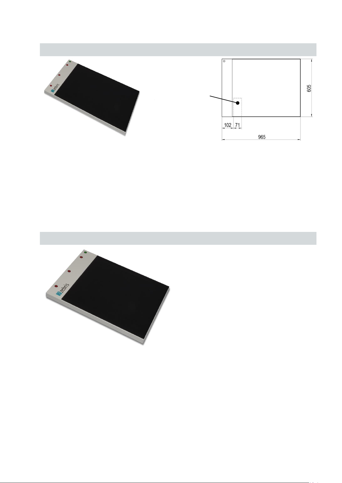
3.2.3 FDM system for jump analysis
Type
FDM-J1.0
REF.-No.
01243200
Outer dimensions
965 x 605 x 21 mm (L x W x H)
Weight
approx.12 kg
Measuring frequency
400 Hz / optional 800 Hz
Number of sensors
60 x 64 / 2560
Sensor surface
810 x 510 mm (L x W)
Resolution
1/2 “ resp. 0.6 sensors / cm²
Infrared interface
integrated
Geben Sie hier eine Formel ein.
Type
FDM-J1.8SQ
REF.-No.
01243210
Outer dimensions
1810 x 1940 x 21 mm (L x W x H)
Weight
approx. 50 kg
Measuring frequency
100 Hz
Number of sensors
96 x 96 / 9216
Sensor surface
1730 x 1730 mm (L x W)
Resolution
3/4 “ approx. 0.3 sensors / cm²
Infrared interface
integrated
Connector box
at bottom side
Page 14
zebris Medical GmbH
FDM Technical Data and Operating Instructions
Page 14/54
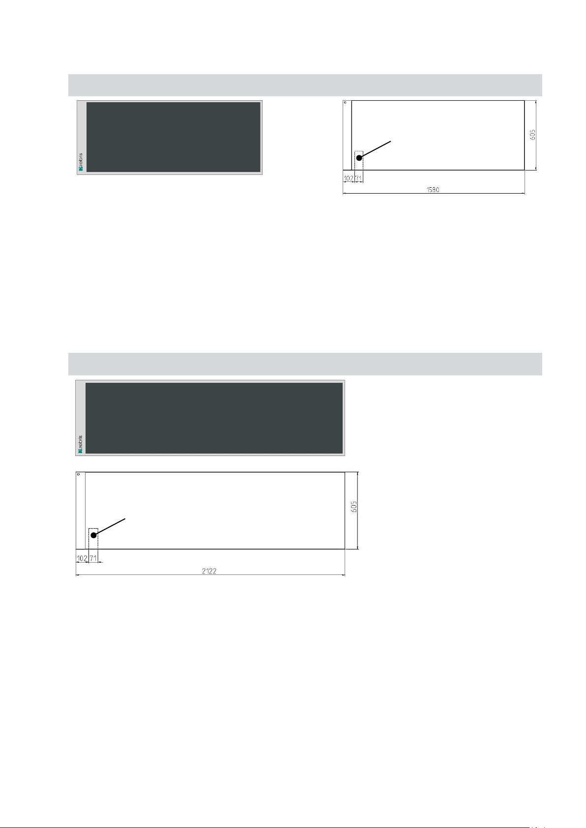
3.2.4 FDM system for stance and gait analysis
Type
FDM-1.5
REF.-No.
01243015
Outer dimensions
1580 x 605 x 21 mm (L x W x H)
Weight
ca. 16,5 kg
Measuring frequency
120 Hz / optional 200 Hz oder 300 Hz
Number of sensors
64 x 176 / 11264
Sensor surface
1440 x 560 mm (L x W)
Resolution
1/3 “ resp. 1,4 sensors / cm²
Infrared interface
integrated
Type
FDM-2
REF.-No.
01243020
Outer dimensions
2122 x 605 x 21 mm (L x W x H)
Weight
approx. 25 kg
Measuring frequency
120 Hz / optional 200 Hz oder 300 Hz
Number of sensors
64 x 240 / 15360
Sensor surface
2030 x 560 mm (L x W)
Resolution
1/3 “ resp. 1,4 sensors / cm²
Infrared interface
integrated
Connector box
at bottom side
Connector box
at bottom side
Page 15

zebris Medical GmbH
FDM Technical Data and Operating Instructions
Page 15/54
Type
FDM-3
REF.-No.
01243030
Outer dimensions
3070 x 605 x 21 mm (L x W x H)
Weight
approx. 35 kg
Measuring frequency
100 Hz
Number of sensors
64 x 352 / 22528
Sensor surface
2980 x 560 mm (L x W)
Resolution
1/3 “ resp. 1,4 sensors / cm²
Infrared interface
integrated
Connector box
at bottom side
Page 16

zebris Medical GmbH
FDM Technical Data and Operating Instructions
Page 16/54
3.2.5 FDM platforms for gait training and rehabilitation applications
Type
FDM-1.7
REF.-No.
01243034
Outer dimensions
1820 x 600 x 21 mm (L x W x H)
Weight
approx. 22 kg
Measuring frequency
100 Hz
Number of sensors
44 x 136 / 5984
Sensor surface
1730 x 560 mm (L x W)
Resolution
1/2 “ resp. 0.6 sensors / cm²
Infrared interface
optional
Type
FDM-2.4
REF.-No.
01243035
Outer dimensions
2510 x 600 x 21 mm (L x W x H)
Weight
approx. 31 kg
Measuring frequency
100 Hz
Number of sensors
44 x 190 / 8360
Sensor surface
2410 x 560 mm (L x W)
Resolution
1/2 “ resp. 0.6 sensors / cm²
Infrared interface
optional
Connector box
at bottom side
Connector box
at bottom side
Ready for installation
in h/p/cosmos parawalk
Page 17

zebris Medical GmbH
FDM Technical Data and Operating Instructions
Page 17/54
3.3 Measuring principle
Kapazitive Meßmatrix
Spaltendekoder
Treiber
Diodenschalter
Schiebe-
register
Diodenschalter
Schiebe-
register
...
Burstgenerator, Ansteuerlogik
Gleichrichter, Verstärker,
8-Bit ADC
Datenbus
Kalibrierdaten
Kalibrier- Flash
RAM
Optokoppler &
Galvanische Trennung mit
Gleichrichter
PC
externes
AC-Netzteil
entspricht
IEC 601
USB
CPU
Programm-
daten
CPU-internes
Flash
Diodenschalter
Schiebe-
register
Diodenschalter
Schiebe-
register
...
The system contains a measuring matrix consisting of capacitive pressure sensors that
are arranged in columns and lines running closely next to each other. For determining the
force distribution over the measuring matrix the capacity proportional to the force exerted
is determined for each individual sensor. To do this, the drive logic generates a number
of sinus burst signals equivalent to the number of columns via the column decoder, and
transmits them to the respective measuring column. The analog signal coupled into the
shift register over the lines is proportional to the pressure-dependent capacity and is
passed on for further processing to the control and signal-processing electronics and
transmitted to the PC from there and shown on the display.
Schematic circuit diagram of the measuring system
Page 18

zebris Medical GmbH
FDM Technical Data and Operating Instructions
Page 18/54
3.4 Controls and Connectors
Status indicator LED
Infrared interface
Measuring area
Connector box
withsafety lock
(bottom side)
All cable connections between platform and PC will be established by the connector box
located at the bottom of the platform.
USB-socket Video-Sync Sync Out/Master Sync In/Slave Powersupply
3.5 Status indicator LED
green flashing The power supply unit is connected to mains and a correct sup-
ply voltage is provided. A USB connection is not established yet
or recognized. The platform is not ready for initialization or
measurement.
green permanent The power supply unit is connected to mains and a correct sup-
orange permanent A measurement is in process.
orange / green flashing A measurement is in process and infrared synchronization sig-
ply voltage is provided. A USB connection is established and
recognized. The platform is ready for initialization or measurement.
nals (from other zebris devices) are received. The orange flashing signalizes that valid synchronization signals are received.
Page 19

zebris Medical GmbH
FDM Technical Data and Operating Instructions
Page 19/54
3.6 zebris SYNC
WARNING
Patient’s safety is guaranteed by means of galvanic separation acc.
to to the provisions of IEC 601-1 when a third party device is synchronized with the FDM system. This allows non medical equipment to be
synchronized with the FDM system as long as such devices are out
of patients reach. Nevertheless the user is completely responsible for
the safety of all third party devices used in combination with the FDM
system.
The correct synchronisation of the measuring data of all coupled systems must be verified before evaluation as soon as a coupling with
devices is carried out, that have not been manufactured by zebris.
zebris does not assume any warranty for the correct functioning and
reliability of the system if the clock signals of external devices do not
correspond to the indicated specifications.
The zebris SYNC serves as a standard solution for the synchronisation of the FDM system
with measuring systems of other manufacturers.
The SYNC-IN and SYNC-OUT sockets provide inputs and outputs for support of „frame by
frame“ In- and Out synchronization. Both sockets are galvanic protected from the platform.
Page 20

zebris Medical GmbH
FDM Technical Data and Operating Instructions
Page 20/54
3.6.1 Synchronization input (SYNC-IN)
View
Front side
Fitting Nut: 30°
Pin assignment
Pin 1 Clk_IN
Pin 2 Activ_IN
Pin 3 GND
View
Solder side
Fitting Nut: 30°
If a third party device is connected to the synchronization input SYNC-IN then depending on
the setting of the configuration window from the application software the measurement will
start/stop or “frame by frame” synchronized by a signal from the third party device. Input is
protected against faulty polarisation and pin 1 is set to +5V ("1") by an internal pull-up- resistor 2.7 k. If this input is set to 0 V ("0") i.e. by a switch or break contact than the SYNCIN is triggered.
Electrical specifications
Input resistance (Pull-Up 5V) 2,7k
VIH (High-Level Input Voltage) ≥ 2,0V
VIL (Low-Level Input Voltage) ≤ 0,8V
Required min. pulse time for triggering 1ms
Built-in LEMO – Jack at Front of ZEBRIS Gauge
Series „00“, 3-pin, fitting Nut 30°
LEMO- Part. No. EPA.00.303.NLN
Respective PlugType of plug for SYNC-IN:
LEMO- Part No. FGA.00 303.CLADxxxx
Page 21

zebris Medical GmbH
FDM Technical Data and Operating Instructions
Page 21/54
3.6.2 Synchronization output (SYNC-OUT)
View
Front side
Fitting Nut: 0°
Pin assignment
Pin 1 +5V
Pin 2 GND
Pin 3 Activ_OUT
Pin 4 Clk_OUT
View
Solder side
Fitting Nut: 0°
If a third party device is connected to the synchronization output SYNC-OUT then depending
on the setting of the configuration window from the application software will trigger a synchronized measurement of the third party device either via start/stop or “frame by frame”
mode.
Electrical specifications
Output resistance 100
High-Level ≥ 2,0V
Low-Level ≤ 0,8V
Respective Plug Type of plug for SYNC-IN
Series „00“, 4-pin , fitting Nut 0°
LEMO- Part. No. EPG.00.304.NLN
Passender Steckertyp für SYNC-OUT
LEMO- Part. No. FGG.00 304.CLADxxxx
Page 22

zebris Medical GmbH
FDM Technical Data and Operating Instructions
Page 22/54
3.6.3 Synchronizing the FDM Platform with video data (Sync Audio)
The Sync-Audio socket serves for synchronizing the platform measurement and recordings
of commercially available video cameras utilizing the external microphone input of the camera.
The synchronization is effected by imprinting a tact signal on the soundtrack of the video
recording. This data is evaluated automatically by the application software WinFDM for synchronizing the platform data and the video signal.
For the connection to the video camera the following synchronization cable is required:
Item No. 01830016 / Video Sync-Control cable,
cable length 7m with amplifier and control LED.
Page 23

zebris Medical GmbH
FDM Technical Data and Operating Instructions
Page 23/54
3.6.4 Infrared synchronization with zebris DAB- Bluetooth (EMG)
FDM-Plattform
USB-interface
Infrared synchronization signal
DAB-Bluetooth
(Infrarotempfänger)
EMG-electrodes
PC
Transmission oft he EMG
signals via Bluetooth interface
Infrared transmitter
For synchronizing the FDM system with the zebris DAB-Bluetooth the optionally available
IR interface which will be integrated within the platform housing is required.
FDM platform and DAB-Bluetooth are synchronized automatically as soon as both devices
have been switched on and a measurement is started.
The following schematic diagram shows the interconnection of the FDM-platform and
the zebris DAB-Bluetooth.
Page 24

zebris Medical GmbH
FDM Technical Data and Operating Instructions
Page 24/54
3.6.5 Combine two FDM platforms oft he same type
NOTE
Be sure to position both platforms as shown below when connecting
them for doubling the walking range.
NOTE
When using the zebris SYNCCam with two combinded plattforms it
must be connected to the “Sync Audio” input of the master platform.
Two FDM platforms of the same type can be combined (Master – Slave) in order to double
usable walking range. To accomplish this task a synchronization cable is required.
Item No. 01830019 / SC-PP Sync. Cable, length 10m
Both platforms have to be connected to separate USB ports of the same PC. By means of
the synchronization cable the „Sync Out“ socket of the master platform has to be connected
to the „Sync In“ socket of the slave platform. The WinFDM software then will recognize the
platform combination automatically and show the corresponding sized measuring area.
Page 25

zebris Medical GmbH
FDM Technical Data and Operating Instructions
Page 25/54
3.7 Spare Parts FDM System
REF- No.
Description
Illustrations
01811513
PS Mascot/2020
Power supply unit 60W/16VDC for FDM
1.5/1.7/2/2.4/3/J
sensors equiv. to EN 60601-1 & UL
01831104
PS MASCOT/2126
Power supply unit 15W/18VDC for FDM
SX/S
sensors equiv. to EN 60601-1 & UL
07200010
zebris FDM Software
for operating system Windows 7 32/64 Bit
79010105
Hardware FDM user manual / english
Printing version is liable to be charged.
Free download of PDF-Files
from zebris Service Center:
79010185
Software zebris FDM user manual / english
Printing version is liable to be charged.
Free download of PDF-Files
from zebris Service Center:
21030071
USB cable A-B, 3 m long
Data connection between
interface box and PC
REF- No.
Description
Illustrations
01540191
SYNCCam
Camera with USB-Cable, synchronizationcable, tripod, inclusive software extension
3.8 Accessories FDM Measuring System
Page 26

zebris Medical GmbH
FDM Technical Data and Operating Instructions
Page 26/54
01540194
SYNCLightCam
Combined solution with Camera and illuminetion, USB-Cable, synchronization cable,
tripod, inclusive software extension
21030321
SYNCCam USB-Cable A-B
USB-Cable for HD-video signal with high
quality plugs, EMC-shielding and ferrites
length 5m
01830016
Video Sync-Control Cable 7.0
Length 7m, both sides phone jack 3,5mm
with amplifier and control-LED
for DV-camcorder
01830041
Video Sync-Control Cable 2.5
Length 2.5m, both sides phone jack 3.5mm,
without amplifier for zebris SYNCCam
21030312
Video Sync-Control Extension Cable
Length 5m, phone jack & socket 3.5mm
01540110
SYNCLight
with 10 power LEDs, power supply unit,
light intensity infinitely variable
VIDEOSYNC, without tripod
01831105
SYNCLight Power Supply Unit
Mains adapter 40W / 24V DC
01540110
SYNCLight Plus
with 10 power LEDs, power supply unit,
light intensity infinitely variable
VIDEO SYNC, PULSE SYNC, zebris SYNC
up to 3 SYNCLight Plus can be combined
into a lighting unit, without tripod.
33102210
SYNCLight plus Power Supply Unit
Mains adapter 110W / 24V DC,
Supports up to 3 SYNC Light plus.
Page 27

zebris Medical GmbH
FDM Technical Data and Operating Instructions
Page 27/54
01850011
SYNCLight plus Adapter Cable
for Master-Slave connection
of up to 3 SYNCLight plus, length 1m
Page 28

zebris Medical GmbH
FDM Technical Data and Operating Instructions
Page 28/54
4 Video-Module
WARNING
The Sync-LEDs are flashing when the camera is disconnected from
the USB port. Therefore it is strongly advised not to look directly into
the camera when it is disconnected in order to avoid dazzling.
NOTE
In order to maintain undisturbed transmission of the video signal it is
mandatory to use high quality USB cables.
Please, only use cables supplied or recommended by zebris for connecting SYNCCam and PC.
USB Socket Typ B
Flash LED‘s
Status-LED
Sync-out
Socket
Sync-in Socket
¼ Inch Tripod-Thread
4.1 SYNCCam
The SYNCCam is an accessory of the FDM-T system and perfectly adapted to be used in
combination with the force distribution measurement. All adjustments of the camera are carried out via hardware setup integrated to the zebris FDM Software. The camera is connected
to the PC by a USB cable of type A-B included within the shipment.
The camera is equipped with ¼ inch tripod threads and can be adapted to zebris tripods as
wells as commercially available camera tripods.
Technical Specifications
REF-No. 01540190
Dimensions 110 x 125 x 15mm (L x W x H)
Weight approx. 190g
Power Supply USB (5V DC / 500mA)
Resolution 1920 x 1080 Pixel (Full-HD) / Autofocus
Frame Rate 30Hz
Synchronization LED-Flash triggered by Sync-IN socket
Mounting ¼ Inch tripod-thread at bottom and back side
Page 29

zebris Medical GmbH
FDM Technical Data and Operating Instructions
Page 29/54
4.2 SYNCLightCam
WARNING
The Sync-LEDs are flashing when the camera is disconnected from
the USB port. Therefore it is strongly advised not to look directly into
the camera when it is disconnected in order to avoid dazzling.
NOTE
In order to ensure failure-free operation of the SYNCLights it is mandatory to keep the black heat sinks at their back side uncovered and
well air circulated at all times.
Power-LEDs
LED-
Heat Sink
¼ Inch Tripod-Thread
Typeplate
The SYNCLightCam is an accessory of the FDM system and perfectly adapted to be used
in combination with the force distribution measurement. All adjustments of the camera are
carried out via hardware setup integrated to the zebris FDM Software. The camera is connected to the PC by a USB cable of type A-B included within the shipment.
The SYNCLightCam is equipped with ¼ inch tripod threads and can be adapted to zebris
tripods as wells as commercially available camera tripods.
Furthermore contains the SYNCLightCam as an integral solution, the LED video illumination.
In order to produce well lighted and tack sharp video captures it is essential to maintain
perfect lighting conditions at the patient’s side. Only with adequate lighting conditions
video cameras can work with shutter times short enough to freeze fast movements and
capture sharp images.
This solution is perfectly matched on the interaction with the FDM system and can be regulated infinitely in its brightness.
The integrated synchronization unit automatically switches the lights on at the start of a
measurement and turns them off again after stopping it.
Page 30

zebris Medical GmbH
FDM Technical Data and Operating Instructions
Page 30/54
Technical Specifications
NOTE
In order to maintain undisturbed transmission of the video signal it is
mandatory to use high quality USB cables.
Please, only use cables supplied or recommended by zebris for connecting SYNCCam and PC.
Status-LED
Light intensityAdjustment
SYNC ModeSwitch
VIDEOSYNC
Sockets (3 mm
Phone Jack) Jack)
Status-LED
Power-
Supply
REF-No. 01540194
Dimensions 220 x 183 x 80mm (B x H x T)
Weight ca. 790g
Power Supply 24V / 36W
Resolution 1920 x 1080 Pixel (Full-HD) / Autofokus
Frame Rate 30Hz
Light Colour / Light Current 6200 K / 1550 Lumen
Synchronization VIDEOSYNC (Ein-/Ausschalten mit der Messung)
SYNC IN Standard zebris Synchronisation
(kompatibel mit SYNC IN/OUT Plattform)
Mounting ¼ Zoll Stativgewinde an der Rückseite
Page 31

zebris Medical GmbH
FDM Technical Data and Operating Instructions
Page 31/54
Interpretation of the STATUS-LED
Modes
Characteristics
Pin Assignment
VIDEO
SYNC IN
ESD - protected, voltage reversal proof input
Input resistance: 38 k (AC)
Signal-Level: AC
Trigger Level: 15 mV
Green Device is ready for use or in operation.
Orange The orange colour indicates when the maximum operation temperature has
been reached. At this point the operation current is reduced automatically
(which results in reduced brightness) in order to prevent the
SYNCLight plus from being damaged by excessive heat.
Power Supply Unit
For operation of the SYNCLight plus a power supply unit needs to be connected.
REF-No. 33102220
Input Output Cable Length
100 – 240 V AC 24 V DC DC-Lead 1.7 m
50 – 60 Hz 40 W Mains Lead Plug Adapter
SYNC-Modus
Page 32

zebris Medical GmbH
FDM Technical Data and Operating Instructions
Page 32/54
4.3 LED Video Lights (SYNCLight / SYNCLight plus)
NOTE
In order ensure failure-free operation of the SYNCLights it is mandatory to keep the black heat sinks at their back side uncovered and well
air circulated all the time.
¼ Inch Tri-
pod-Thread
Type-
plate
Power-LEDs
Lower
Connector Board
Upper
Connector Board
LED-
Heat Sink
In order to produce well lighted and tack sharp video captures it is essential to maintain
perfect lighting conditions at the patient’s side. Only with adequate lighting conditions
video cameras can work with shutters times short enough to freeze fast movements and
capture sharp images.
The LED video lights SYNCLight and SYNCLight plus are accessories of the FDM systems
and perfectly adapted for use in combination with zebris SYNCCam as well as the force
distribution measurement. Their brightness can be adjusted infinitely.
The integrated synchronization unit automatically switches the lights on at the start of a
measurement and turns them off again after stopping it.
Both SYNCLights are equipped with ¼ inch tripod threads and can be adapted to zebris
tripods as well as commercially available camera tripods
Page 33

zebris Medical GmbH
FDM Technical Data and Operating Instructions
Page 33/54
4.3.1 SYNCLight
Status-
LED
Brightness-
Adjustment
SYNC ModeSwitch
VIDEOSYNC
Sockets (3mm Phone
Power-
Supply
If the synchronization signal from the interface box of the FDM-T system is connected to the
VIDEOSYNC socket the SYNCLight will be automatically turned on and off when a measurement is started or stopped.
In order to use the synchronization set the SYNC-Mode switch to position SYNC. At position CONT the SYNCLight plus is switched on permanently. The DIMMER can be used to
adjust the light brightness individually no matter which operation mode is set.
Technical Specifications
REF-No. 01540110
Dimensions / Weight 155 x 210 x 38mm (L x W x H) / approx. 640g
Power Supply 24V DC / 36W
Light Colour / Light Current 6200K / 1550 Lumen
Synchronization VIDEOSYNC (On-/Off with force measurement)
Mounting ¼ Inch tripod thread at back side
Interpretation of the STATUS-LED
Green Device is ready for use or in operation.
Orange The orange colour indicates when the maximum operation temperature has
been reached. At this point the operation current is reduced automatically
(which results in reduced brightness) in order to prevent the
SYNCLight plus from being damaged by excessive heat.
Power Supply Unit
For operation of the SYNCLight a power supply unit needs to be connected.
REF-No. 3310.2220
Input Output Cable Length
100 - 240V AC 24V DC DC-Lead 1.7m
50 - 60Hz 40W Mains Lead Plug Adapter
Page 34

zebris Medical GmbH
FDM Technical Data and Operating Instructions
Page 34/54
4.3.2 SYNCLight plus
Brightness-
Adjustment
SYNC ModeSwitch
VIDEO SYNC
Sockets (3mm Phone Jack)
Power-OUT
PULSE SYNC
(Industrial Camera)
Power-
Supply
Status-
LED
zebris
SYNC IN
The SYNCLight plus supports the zebris VIDEOSYNC as well as more complex synchronization modes that may be required for use of industrial cameras.
In order to use the synchronization modes set the SYNC-Mode switch to position SYNC.
At position CONT the SYNCLight plus is switched on permanently. The DIMMER can be
used to adjust the light brightness individually no matter which operation mode is set.
Up to 3 SYNCLight plus can be combined into a lighting unit. Therefore they have to be
connected with an adapter cable. The adapter cable provides power supply as well as transmission for the synchronization signals.
Technical Specifications
REF-No. 01540120
Dimensions / Weight 155 x 210 x 38mm (L x W x H) / approx. 640g
Power Supply 24V DC / 36W
Light Colour / Light Current 6200K / 1550 Lumen
Synchronization VIDEO SYNC On-/Off with force measurement
PULSE SYNC Shutter Sync. with industrial cameras
SYNC IN Standard zebris synchronization
(Compatible with SYNC IN/OUT platform)
Mounting ¼ Inch tripod thread at back side
Master – Slave Operation off max. 3 SYNCLight plus by adapter cable 185.0011/SL-C1
Interpretation of the STATUS-LED
Green Device is ready for use or in operation.
Orange The orange colour indicates when the maximum operation temperature has
been reached. At this point the operation current is reduced automatically
(which results in reduced brightness) in order to prevent the
SYNCLight plus from being damaged by excessive heat.
Page 35

zebris Medical GmbH
FDM Technical Data and Operating Instructions
Page 35/54
4.3.3 Power Supply Unit SYNCLights
Modes
Characteristics
Pin Assignment
VIDEO
SYNC IN
ESD - protected, voltage reversal proof input
Input resistance: 38K (AC)
Signal-Level: AC
Trigger Level: 15mV
VIDEO
SYNC OUT
ESD - protected, voltage reversal proof input
The signal from the VIDEO SYNC IN is directly
transmitted to VIDEO SYNC OUT and can be
used for control of additional devices.
SYNC IN
ESD - protected, voltage reversal proof input
Input resistance: 38K (Pull-Up)
VIH (High-Level Input Voltage): ≥ 3.7V
VIL (Low-Level Input Voltage): ≤ 3.0V
Both Signals can be used as Trigger input
(“AKTIV” as well as “CLK”) and possess the
same effect.
The signal switches the LED light on to the
brightness level pre-selected by the DIMMER
The SYNC IN is the standard synchronization
tool (zebris SYNC) of all zebris measuring systems and intended to be used to synchronize
the lighting system with the measuring signal of
other zebris measuring systems (e.g. CMS).
In order to use SYNC IN the SYNC mode
switch has to be set to position SYNC.
3-Pin Socket
Pin1: CLK
Pin2: AKTIV
Pin3: GND
Socket Type
LEMO- Part No.
FGA.00 303.CLADxxxx
For operation of the SYNCLight plus a power supply unit needs to be connected.
REF-No. 33102210
Input Output Cable Length
100 - 240V AC 24V DC Mains Lead 1.7m
50 - 60Hz 110W DC-Lead 1.7m
SYNC-Modes
Page 36

zebris Medical GmbH
FDM Technical Data and Operating Instructions
Page 36/54
Modes
Characteristics
Pin Assignment
PULSE
SYNC
ESD - protected, voltage reversal proof input
Input resistance: 2K (Pull-Up)
VIH (High-Level Input Voltage): 2.0V
VIL (Low-Level Input Voltage): 0.8V
Polarity: Lo Active
When mode PULSE SYNC is used LED brightness is set to 150%.
The shutter output of industrial high speed cameras can be used as trigger signal for the PULSE
SYNC.
By utilizing pulsed light optimal lighting conditions
for industrial cameras can be accomplished without being too bright or disturbing for the human
eyesight.
In order to use PULSE SYNC the SYNC mode
switch has to be set to position SYNC.
6-Pin Socket
Pin4: Input
Pin5: GND
Socket Type
HIROSE HR10A-7P-6S
Camera Trigger
Input
Begin of
Illumination
Timing Properties when
switching the Light ON:
should be preset to this Value.
Delay: 50µS
Camera Trigger
End of
Illumination
No Delay!
Timing Properties when
Delay of 50µS
The cameras Trigger-Output
Input
switching the Light OFF:
No Delay (0µS)
No adjustment of
Trigger-Output necessary!
Page 37

zebris Medical GmbH
FDM Technical Data and Operating Instructions
Page 37/54
5 Operation of the FDM System
WARNING
Be sure that all the mains and connection cables are laid safely and that
they are protected against stepping on, so that nobody can trip over
them. Check all the cables and the connection plug regularly for any
damage.
The cables therefore can be laid under a cable protection or fixed to
the floor using a tape if necessary.
5.1 Set up the measuring System
For the commissioning of the FDM platform the suitable power supply, a USB cable type AA as well as the installation CD with the FDM application software are necessary. All components are included in the scope of delivery of the FDM measuring system.
The underground of the set-up location must be plain and horizontal.
The platform must be set up on a slip-proof underlay or installed in a catwalk, so as
to exclude any danger to the test person caused by the platform sliding.
Do not set up the platform near a source of heating or in direct sunlight in front of a
window as a rise in temperature can lead to inaccurate measuring results.
Set-up the measuring system in a way, that the socket for the mains connection is
accessible easily at all times and that the device can be separated from the power
supply.
Once the measuring system is set up safely and horizontally, it can be connected to
the power supply and put into operation.
5.2 How to switch the platform On/Off
The platform is switched on and off by software control as soon as the zebris FDM software
on the PC is started. If the device has been connected correctly, the green LED operating
indicator illuminates on the housing of the platform.
Page 38

zebris Medical GmbH
FDM Technical Data and Operating Instructions
Page 38/54
5.3 Anschluss des Messsystems an das Versorgungsnetz
WARNING
Exclusively use the power plug approved by zebris for the operation
of the FDM platform, which is suitable for the power supply of your
platform.
Input
Output
Cable
Length
100 - 240 V AC
18V DC
AC Cable
---
50 - 60 Hz
15 W
DC Cable
6m
For the connection of the FDM platform with the mains, connect the power supply with the
mains socket and the power socket in the connector compartment.
Power Supply MASCOT/2126 REF-No. 01831104
For the following platforms: FDM-SX
FDM-S
Technical Data
Pin arrangement / polarity
Pin arrangement and polarity is identically to Mascot/2020
Page 39

zebris Medical GmbH
FDM Technical Data and Operating Instructions
Page 39/54
Power Supply Mascot/2020 REF-No. 01811513
Input
Output
Cable
Length
100 - 240 V AC
16V DC
AC Cable
1,7 m
50 - 60 Hz
60 W
DC Cable
5 m
NOTE
Before connecting the measuring system to the mains, compare the
nameplate indications of the power supply and the treadmill in terms
of mains voltage and mains frequency with the local characteristics.
Only connect when they are in accordance.
WARNING
Carry out a visual examination of power supply, mains connection
voltage and socket as well as earthing contacts before connecting
resp. commissioning the measuring system. Damaged power supplies, cables or connection sockets immediately must be replaced by
a person authorised to do so.
„-“Contakt: Outer contact oft
he hollow plug
„+“Contact: Inner contact of
the hollow plug
For the following platforms: FDM-1.5, FDM-2, FDM-3
FDM-1.7, FDM2.4
FDM-J1, FDM-J1.8SQ
Technical Data
Pin arrangement / polarity
Page 40

zebris Medical GmbH
FDM Technical Data and Operating Instructions
Page 40/54
5.4 Computer requirements
WARNING
If the computer is not supplied with the measuring system, the manufacturer shall not be held liable for any damage or malfunctions arising
from a faulty coupling. Should additional hardware be built into the
computer or software installed, the manufacturer shall not be liable for
any malfunctions or damage occurring.
The computer must be CE marked and fulfil the requirements of DIN
EN 60950 resp. DIN EN 60601-1.
WARNING
The FDM measuring system is not designed for the operation within
a network/data network. The connection of the system with a networtk/data network can cause unforeseen risks for patients or third
parties. If the zebris FDM software shall be installed in a network/data
network, the operator is obliged to determine, analyse, evaluate and
control the risks that are connected with doing so – particularly with
regard to the aspects data protection, virus security, updates of the
operating system and regular backups. Risk considerations have to
include subsequent changes of the network/data network, like e.g.
update/upgrade of devices and components that are connected to the
network.
NOTE
Please make absolutely sure that you have installed the zebris
software before connecting the FDM platform to the computer
using the USB cable.
NOTE
How to solve problems with the hardware driver
Should problems with the hardware driver of the FDM platform occur
then disconnect the platform from the PC and restart it. Now proceed
with installing the WinFDM software another time and reconnect the
platform when the installation procedure has been finalized.
As a rule, the measuring system FDM is supplied together with a computer. If the system is
to be operated using other computers or components, the user must then inquire whether
the intended coupling guarantees the necessary safety for the test person, the operator and
the surroundings by consulting the manufacturer, the authorized zebris sales partner or by
asking a specialist.
Please refer to the zebris FDM Software Manual for informations according to PC requirements.
5.5 Installing the zebris FDM software
If your measuring system is delivered without PC/laptop, please install the application software before connecting the measuring system to the computer. Please find information on
the installation in the user manual of the zebris FDM software.
If the platform is connected without installing the software before, problems when installing
the device driver may occur and the system does not work.
Page 41

zebris Medical GmbH
FDM Technical Data and Operating Instructions
Page 41/54
5.6 Closing the safety lock of the plug tray
safety lock
Finally connect the USB socket in the connector compartment and a free USB interface of
your computer by using the provided USB cable. Your measuring system is now ready for
use. The control of a measurement exclusively is carried out via the zebris FDM software.
Therefore, please carefully read the zebris FDM user manual.
If the power supply unit and the USB cable are connected to the sockets of the platform,
please close the lid of the safety lock and fasten it to the housing by means of the four
screws supplied with the platform.
5.7 Setting the system out of operation
In order to set the system out of operation please close the WinFDM software first, then exit
the Windows operating system and shut down the PC. In the next step disconnect the power
supply unit of the FDM sensor and the treadmill from mains supply.
Page 42

zebris Medical GmbH
FDM Technical Data and Operating Instructions
Page 42/54
5.8 Recommendations for recording data
To receive significant data from FDM systems some principle guidelines should be followed.
This chapter describes the ideal conditions for recording measurement data: The following
points refer to the data reception of a person walking and describe the ideal measurement
situation.
5.8.1 Walking range
The best conditions for measurements with platforms of the FDM-S type will be reached by
integration of the system in a walking range. The complete walking range must be plane
with the surrounding floor. This way the test person won’t know the position of the platform
and gives a workaround to the tendency that test persons try to walk exactly on the sensor
area. The width of the stage should be about 1,20m. We recommend a distance of about
4m from start to FDM-S platform and no less than 3m behind. With such a walking stage it
is easier to measure normal walking without acceleration or deceleration.
Of course the same set up can be used to measure with the method of first step. The first
step method is described as follow: The patient stands on one side of the platform in a
distance to reach the platform by the first step. For measurement the patient hits the sensor
area by the first step and moves on. This kind of measurement guaranties reproducible steps
and results. Notice: These results differ more or less from these by normal walking.
5.8.2 Data recording
Please observe the exercise of the patient strictly. Only steps where the complete ground
contact of the foot is located on the sensor area may be used for evaluation. If not the complete foot area was measured by the system (foot did partially not hit the sensor area) the
step can not be evaluated.
5.8.3 Gait velocity
For the measurement a normal (individual) and constant walking velocity is necessary. Ideally an additionally measurement, e.g. by photo sensors, can proof the velocity for notice.
Naturally the patients adapt to the measurement situation within a few minutes. After a few
trials, walking seems normal. A change in velocity of about 5 % is non-effective.
5.8.4 Posture
A visual control of the behaviour pattern of normal gait is recommended. Trials with atypical
behaviour pattern should be deleted from interpretation. The patient has to look straight
ahead and must not be disturbed by paying attention to the platform or monitor. Marks on
the wall in front of the patient can provide orientation to hit the platform.
5.8.5 Acrosclerosis
Different measurements (e.g. P.R. Cavanagh, The Foot (1994) 4, 123-135) show an increase of plantar pressure peaks of about 30 % by acrosclerosis (e.g. weals). The interpretation of measurement data has to include the existence of plantar acrosclerosis.
Page 43

zebris Medical GmbH
FDM Technical Data and Operating Instructions
Page 43/54
6 Control measures, Preparation, Disposal
Scheduled maintenance of the system is essential in order to prevent damage
and guarantees the safety of the device. All methods concerning the system’s
maintenance and disinfection mentioned in this user manual should be carried out on a
regular basis.
Should any malfunctions and/or defects be determined or suspected, the device must be
put out of operation immediately, marked as "Out Of Service" and prevented from being
used by removing the mains cable. In such case be sure to contact the manufacturer or
an authorized sales partner.
The maintenance of the device or its accessories, going beyond the procedures described
in this user manual, must exclusively be carried out by zebris Medical GmbH or a person
who has been explicitly authorized by zebris to do this.
Be sure to switch of the measuring system and disconnect it from mains supply before
starting any maintenance work.
6.1 Mandatory periodic inspections and STK
The zebris Medical GmbH does not stipulate any safety-related control
for the FDM system.
For maintaining the correct state of the electrical equipment, checks and technical
safety inspections have to be carried out repeatedly (e.g. within Germany, acc. to
BGV A3, and accident prevention regulations and technical safety tests according to
the Medical Device Operating Regulations). Here it should be noted that standard
regulations for electrical devices are concerned here and not measures that are specific to zebris.
For safety reasons it is recommended before each use of the measuring system, to
check the correct state of all the connection leads, as well as the mains cable, mains
plug and mains socket. Should certain parts be damaged, these must be replaced
before continuing to use the measuring system.
Immediate maintenance measures are to be carried out if:
a) Fluid enters the device
b) Cable or cable connections habe been damaged
c) Parts of the sensors were damaged
d) Covers habe been damaged
e) A malfunction or a fault is suspected or has been detected
If the type plate or other important labels (warning notices) are damaged or oblite-
rated they have to be replaced by the manufacturer for safety reasons.
Page 44

zebris Medical GmbH
FDM Technical Data and Operating Instructions
Page 44/54
6.2 Checking the FDM Sensor
WARNING
The measuring system must be checked at regular intervals to ensure
that the measuring system is functioning properly.
6.2.1 Control measures
Should any damage to the measuring surface become evident (e.g. something fell hard on
the black measuring surface), no further measurements must be taken. If visible damages
are detected not further measurements are permitted.
After carrying out a baseline measurement, no measuring values may be shown for a condition without any load. In addition, the force distribution images are to be checked regularly
for untypical measuring patterns. These include above all, line or column-shaped measuring
patterns deviating from the surrounding values.
Whenever faults occur or in case of doubt, the manufacturer or sales partner authorized by
zebris must always be contacted.
6.2.2 Calibration measures
The measuring accuracy of the sensors for the force distribution measurement is to be
checked from time to time using a defined application of force.
To do this, the user, knowing the body weight, can stand on the platform on one foot. The
platform must show the approximate body weight, taking the force of gravity, the sensors at
the edges that may not be subject to the full pressure, and the measuring tolerance into
consideration.
In case of deviations larger than > ±5% of max range a recalibration at manufacturers side
is required.
Should the display be incorrect, a recalibration by the manufacturer is required.
Page 45

zebris Medical GmbH
FDM Technical Data and Operating Instructions
Page 45/54
6.3 Troubleshooting
NOTE
Please find further information on error messages and troubleshooting in the user manual of the zebris FDM software.
NOTE
In order to support you the best way possible in case of malfunction
of your FDM measuring system, our service employees need the following information:
Please check the following points if technical malfunctions should occur:
Is the FDM platform properly connected to the mains?
(LED flashes green)
Is the USB connection between platform and the measuring PC properly con-
nected?
(LED flashes green when the USB port and the power supply are connected to the
PC and the device driver has been installed correctly.)
Are all further components of the measuring system (infrared synchronisation with
zebris DAB-Bluetooth, video camera) properly connected?
Checklist for the reception of error messages
Device type + serial number of the FDM platform
Please find the serial number on the left-hand side of the platform close to the connector compartment.
Version of the zebris FDM software
Version of the operating system of your measuring PC
e.g. Windows 7 Professional Servicepack 1
(Call under Windows 7: Windows Start button Control Panel System)
Further components being connected to the measuring system
e.g. Infrared synchronisation (IR) with zebris DAB-Bluetooth, video camera
List of all USB devices that are connected to the measuring PC
e.g. mouse, printer, other measuring systems etc.
Screenshot of the error message, or exact wording
e.g. “EMG adapter not found.”
Precise and detailed description of the procedure that has lead to the error mes-
sage.
e.g. Measurement “Type A” started, then clicked on button “B”, afterwards carried out movement “C”,
switched to function “D”, when switching back, the error message xyz occurred etc.
Page 46

zebris Medical GmbH
FDM Technical Data and Operating Instructions
Page 46/54
6.4 Cleaning and disinfection
NOTE
Do not use any aggressive agents to clean the measuring system.
WARNING
Please be absolutely sure to switch off the device and pull the mains
plug out of the socket before you commence disinfecting and cleaning
WARNING
No spray disinfection!
Spray disinfection can destroy the highly precise
measurement sensors of the platform.
NOTE
If you apply disinfection agent be sure to follow the recommendations
given by the manufacturer of the disinfection agent strictly. Especially
consider the rules concerning the commended application time of the
agent.
WARNING
Due to danger of confusion, chemicals that are necessary for the disinfection or cleansing exclusively must be stored, prepared and provided in containers that are appropriate for this purpose.
NOTE
In order to demonstrate that disinfection was successfully done, it is
recommended to put up a sign on the platform, saying “disinfected”.
6.4.1 Cleaning
The platform and accessories are cleaned with a moist cloth while the device is switched off
and the mains plug taken out.
6.4.2 Manuelle Desinfektion
The platform can be disinfected by wiping over with suitable agents. To clean, wipe the
platform with a cloth soaked in disinfection liquid.
Recommended disinfection agent
Composition approx. 25% ethanol, 35% Propanol
E.g. Mikrozid Liquid / Schülke & Mayr or similar agents
Page 47

zebris Medical GmbH
FDM Technical Data and Operating Instructions
Page 47/54
6.5 Disposal
6.5.1 Packaging
All transport packagings delivered by zebris can be recycled within Germany via the local recycling depots. In order to provide the reuse of the
recyclable material contained in the packagings, the zebris Medical GmbH
takes part in the dual ZENTEK system that takes over the proper disposal
of packagings.
6.5.2 Disposal of electronics
This symbol states that according to the directive on waste electrical
and electronic equipment (2012/19/EEC) the product must not be
disposed by means of the domestic waste system. Within Europe
this device must be forwarded to a specific waste disposal system.
Therefore regular disposal is carried out by the manufacturer. For
this purpose the system should be shipped to the manufacturer and
will be forwarded to regular disposal by zebris.
The improper interaction with electronic waste could lead to negative effects for the environment and the public health because of
potential hazardous materials which are frequently contained within
electric and electronic devices. Additionally with the proper disposal
of this product you will contribute to the effective use of natural resources.
Accumulators and batteries
Accumulators and batteries must not be disposed of with domestic waste! In the interest of
environmental protection, the consumer is legally obliged (battery regulation) to return old
and used batteries. Used accumulators and batteries can be disposed of at the collecting
points of the community or where batteries of the relevant kind are sold. For consumers, the
batteries are taken back free of charge.
Page 48

zebris Medical GmbH
FDM Technical Data and Operating Instructions
Page 48/54
7 Safety standards and system classification
WARNING
The FDM System may only be coupled with other electrical devices if
these conform to the provisions of DIN EN 60950 or DIN EN 60601-1
or zebris Medical GmbH has confirmed their compatibility.
WARNING
When coupling several devices to one measuring station, please note
that no danger through summation of leakage currents can occur.
Devices that are in direct contact with the patient and that are commonly used in a medical electrical system, as a whole have to fulfil all
requirements of DIN EN 60601-1:2006 section 11.
There is a danger of electric shock when touching devices that are
not grounded separately.
The following information and warnings are listed according to the requirements of the standard DIN EN 60601-1:2006, section 11 for medical, electrical systems and must be applied
when operating the FDM system for medical purposes.
7.1 Classification acc. to Annex IX of Directive 93/42/EEC
If your FDM platform features a CE sign on the nameplate with a four-digit identification
number of a notified body (0535), the system is then classified as medical product Class I
with measuring function.
7.2 Safety of medical electrical devices
The FDM platform fulfils the requirements of the standard DIN EN 60601-1:2006.
Classification of the FDM Sensor according to DIN EN 60601-1
Type BF
Safety class II
Steady state conditions
Unsuitable for use in an oxygen-enriched atmosphere
7.2.1 Connecting the FDM-System to other electrical devices
(siehe auch DIN EN 60601-1:2006 Abs. 16 Medizinische Elektrische Systeme)
Page 49

zebris Medical GmbH
FDM Technical Data and Operating Instructions
Page 49/54
7.2.2 Vicinity of the patient / test person
WARNING
When operating the system, the user [2] must ensure that he does not
touch the PC [3] and the patient [1] at the same time. The same applies for all other non-medical, electrical components; they may only
be used outside the patient's vicinity.
Furthermore, the user must ensure, never to touch the contacts of the
connectors of the interface box and the patient at the same time.
In case of non-observance, dangerous leakage currents can occur.
WARNING
The computer and other non-medical electrical equipment (e.g. camera equipment, lights) have to be located beyond the reach of the patients (1.5m).
r = 1,5 m
[1]
[3]
[2]
For the definition of the patient’s surroundings, experience shows that a value of 1,5 m dis-
tance to the patient is optimal.
The following components of the FDM system may be used in the vicinity of the patient:
FDM Sensor
zebris Measuring Systems for medical purposes (e.g. CMS20, DAB Bluetooth)
Page 50

zebris Medical GmbH
FDM Technical Data and Operating Instructions
Page 50/54
7.2.3 Use of multiple sockets
WARNING
If multiple sockets are used for connecting the FDM-T system or its
components, the following safety regulations are to be observed:
WARNING
Coupling the mains connection of components of medical electrical
systems and other, not supplied components by using multiple sockets according to EN 60601-1 is a very dangerous practice.
It is possible for excessive touch currents to occur if mains are connected without the user having any respective expert knowledge.
Due to these complications zebris Medical GmbH urgently advises not
to use multiple sockets for operation of the system.
The following information and warnings are based on the requirements of the Standard DIN
EN 60601-1:2006, Section 11 for medical electrical equipment and have to be enforced
when the FDM system is used for medical purposes.
Always connect the treadmill and FDM sensor directly to mains supply by using a sepa-
rate wall socket with a tested protective earth conductor and separate fuse.
Multiple sockets can be used without causing any danger for connecting the PC and other
electrical accessories (video camera, illumination) outside the patients’ vicinity.
Multiple sockets must not be placed on the floor to avoid accidentally penetration of liquids
or mechanical damages.
It is forbidden to use extension cables or several multiple sockets connected in series.
In commercially available multiple sockets, system components set up within and outside
the vicinity of the patient must never be plugged in together. (Example: It is forbidden to
connect the PC and the power supply unit of the FDM sensors to the same multiple
socket.)
If multiple sockets are used jointly for components of the FDM system, that are allowed
to be located within the vicinity of the patient (e.g. treadmill, FDM sensor or other zebris
measuring systems) and components that have to be outside the vicinity of the patient
(e.g. PC, video camera), the multiple socket and complete interconnection of the system
must adhere to all the requirements of DIN EN 60601-1:2006 Section 16. If necessary,
an isolating transformer is to be used for an arrangement of this kind, and the ground
leakage current in the protective earth conductor of the multiple sockets must not exceed
5 mA. The adherence to the maximum permissible patient leakage currents is to be verified by measuring. If a multiple socket was integrated after setting the system into operation for the first time, no additional device may be connected to it (use multiple sockets
with locking covers for this purpose)
Page 51

zebris Medical GmbH
FDM Technical Data and Operating Instructions
Page 51/54
7.3 Electromagnetic compatibility Guideline & Manufacturer Declaration
WARNING
Even though the motion analysis system FDM fully complies with the
requirements of the standard EN 60601-1 it cannot be totally excepted
that portable and mobile RF communications equipment can affect
the system. If ever possible such devices should not be operated
within the system environment during measurements
WARNING
The use of accessories, particularly cables for connecting to the PC,
that are not supplied by zebris for use with the FDM system, or explicitly recommended for use with the device, can lead to a reduced resistance to EMC interference of the FDM system.
WARNING
The FDM measuring system should not be operated in the vicinity of
e.g. X-ray equipment, motors or transformers with a high connected
load, as electrical or magnetic interference fields can influence the
measurements. The same is applicable for neighboring power lines
and equipment without a CE mark. Should operation next to possible
sources of interferences be necessary it is mandatory to check and
verify the correct function of the system.
NOTE
In the case of over voltages or voltage dips (even short-term) of more
than 50% of the mains voltage, functional faults can occur. When such
high voltage dips or complete voltage failures occur, the measurement is interrupted and the measuring data is discarded. Finally the
measurement has to be re-started, and if need be, also the connected
PC.
The measuring system FDM fulfils all requirements for EN 60601-1-2
(Medical Electrical Equipment - Part 1-2: General requirements for basic safety and essential performance - Collateral Standard: Electromagnetic compatibility - requirements and
tests)
Inspecting authority: SCHWILLE – ELEKTRONIK
Produktions- und Vertriebs GmbH
Benzstrasse 1A
85551 Kirchheim
Detailed information on EMC values and information supplied by the manufacturer can be
found in the tables in this Section of the User Manual.
Electrical equipment in the medical field is subject to particular precautionary measures as
regards the EMC (Electromagnetic Compatibility) and must be installed and put into operation in accordance with the instructions given below.
Page 52

zebris Medical GmbH
FDM Technical Data and Operating Instructions
Page 52/54
Guidelines and Manufacturer's Statement - Electromagnetic Emission
The FDM-T force-distribution measuring system is intended for use in the electromagnetic environment described below. The customer
or user of the FDM-T force-distribution measuring system should ensure that it is operated in such an environment.
Emitted interference measurements
Compliance
Electromagnetic environment guidelines
RF emissions
acc. to CISPR 11
Group 1
The FDM-T force-distribution measuring system uses RF energy exclusively for its internal functions. Therefore its RF emission is very
low and it is unlikely that electronic equipment in close proximity will
experience interference.
RF emissions
acc. to CISPR 11
class B
The FDM-T force-distribution measuring system is intended for use in
all facilities including those in residential areas and those directly connected to a public utility network also supplying buildings used for residential purposes.
Emission of harmonic oscillations
acc. to IEC 61000-3-2
class B
Emission of voltage fluctuations /
flickers acc. to IEC61000-3-3
in compliance
Guidelines and Manufacturer's Statement - Electromagnetic Interference Immunity
The FDM-T force-distribution measuring system is intended for use in the electromagnetic environment described below. The customer or user of the FDM-T force-distribution measuring system should ensure that it is operated in such an environment.
Interference immunity
tests
IEC 60601 test levels
Compliance level
Electromagnetic environment guidelines
Electrostatic discharge
(ESD)
acc. to IEC 61000-4-2
± 6 kV contact discharge
± 8 kV atmospheric
discharge
± 6 kV contact discharge
± 8 kV atmospheric
discharge
Flooring should be of wood or concrete or
laid with ceramic tiles. If the flooring is made
of synthetic material, the relative humidity
must be at least 30%.
Fast transient
electrical interferences/bursts
acc. to IEC 61000-4-4
± 2 kV for power lines
± 1 kV for input
and output lines
± 2 kV for power lines
± 1 kV for input
and output lines
The quality of the supply voltage should be
the same as the voltage of a typical business
or hospital environment.
Surges acc. to
IEC 61000-4-5
± 1 kV differential mode
voltage
± 2 kV common mode
voltage
± 1 kV differential mode
voltage
± 2 kV common mode
voltage
The quality of the supply voltage should be
the same as the voltage of a typical business
or hospital environment.
Blackouts, brownouts and
fluctuations of the power
supply acc. to
IEC 61000-4-11
< 5% UT
(> 95% crash of the UT)
for ½ period
40% UT
(60% crash of the UT)
for 5 periods
70% UT
(30% crash of the UT)
for 25 periods
< 5% UT
(> 95% crash of the UT)
for 5 s
< 5% UT
(> 95% crash of the UT)
for ½ period
40% UT
(60% crash of the UT)
for 5 periods
70% UT
(30% crash of the UT)
for 25 periods
< 5% UT
(> 95% crash of the UT)
for 5 s
The quality of the supply voltage should be
the same as the voltage of a typical business
or hospital environment. If the user of the
FDM-T force-distribution measuring system
requires the continuation of functionality also
after power interruptions/disruptions, it is
recommended to provide the FDM-T forcedistribution measuring system with power
from an uninterruptible power supply.
Magnetic field with supply
frequency (50/60 Hz)
acc. to IEC 61000-4-8
3 A/m
Not tested as no influence is
possible on the device within
the specified test level. (see
Note B)
Magnetic fields of the mains power frequency should comply with the typical values
of a business and hospital environment.
NOTE UT is the AC main voltage prior to applying the test levels.
Page 53

zebris Medical GmbH
FDM Technical Data and Operating Instructions
Page 53/54
Guidelines and Manufacturer's Statement - Electromagnetic Interference Immunity
The FDM-T force-distribution measuring system is intended for use in the electromagnetic environment described below. The customer
or user of the FDM-T force-distribution measuring system should ensure that it is operated in such an environment.
Interference immunity
tests
IEC 60601
test levels
Compliance
level
Electromagnetic environment guidelines
Portable and mobile wireless sets should not be used in closer proximity to the FDM-T force-distribution measuring system, including the cables, than the recommended safety distance, that is calculated on the
basis of the formula suitable for the transmitting frequency.
Recommended safety distance:
Conducted RF interference
quantities acc. to IEC
61000-4-6
3 V
eff
150 kHz
to 80 MHz
3 V
eff
Pd 2.1
Radiated RF interference
quantities acc. to IEC
61000-4-3
3 V/m
80 MHz
to 2.5 GHz
3 V/m
Pd 2.1
80 MHz to 800 MHz
Pd 3.2
800 MHz to 2.5 GHz
With P as the rated output of the transmitter in watts (W) according to
the information provided by the manufacturer of the transmitter und d
as the recommended safety distance in meters (m).
The field strength from fixed RF transmitters as determined by an electromagnetic site survey a is less than the compliance level b in all the
frequencies.
Interference is possible in the proximity of devices featuring the follow-
ing pictograph
NOTE 1
The higher value applies in the case of 80 MHz and 800 MHz
NOTE 2 These guidelines may not be applicable in all situations. The spread of electromagnetic waves is influenced
by absorption and the reflections of buildings, objects, and people
a
The field strength of stationary transmitters, such as the base stations of mobile phones and land mobile services, ham radio
stations, AM and FM radio and TV broadcasters is theoretically not 100% predictable. A site study is recommended to determine
the electromagnetic environment as a result of stationary RF transmitters. If the measured field strength at the site of the FDM-T
force distribution measuring system exceeds the compliance levels listed above, the FDM-T force distribution measuring system
must be monitored to document its proper functionality at every place of application. Additional measures might become necessary, e.g. modifying the orientation or moving the location of the FDM-T force-distribution measuring system, if unusual performance characteristics are observed.
b
The field strength is less than 3 V/m for the frequency range of 150 kHz to 80 MHz
Recommended Safety Distances between Portable and Mobile RF Telecommunications Devices and
the FDM-T/FDM-T force-distribution measuring system
The FDM-T force-distribution measuring system is intended for use in an electromagnetic environment where RF interference quantities
are controlled. The customer or user of the FDM-T force-distribution measuring system can contribute towards preventing electromagnetic emissions by complying with the minimum distance between portable and mobile RF telecommunications devices (transmitters)
and the FDM-T force-distribution measuring system, as recommended below in accordance with the maximum output power of the
communication device.
Rated output of the transmitter (W)
Safety distance based on the transmitting frequency (m)
150 kHz to 80 MHz
Pd 2.1
80 MHz to 800 MHz
Pd 2.1
800 MHz to 2.5 GHz
Pd 3.2
0.01
0.12
0.12
0.23
0.1
0.38
0.38
0.73
1
1.2
1.2
2.3
10
3.8
3.8
7.3
100
12
12
23
The safety distance for transmitters with a rated output not listed in the table above, can be calculated by applying the formula corresponding to the
respective column, whereby P is the rated output of the transmitter in watts (W) as specified by the transmitter manufacturer.
NOTE 1
For calculating the recommended safety distance of transmitters in the frequency range of 80 MHz to 2.5 GHz,
an additional factor of 10/3 was used to reduce the probability of a mobile/portable telecommunications device
taken unintentionally into the patient's area, causing interference.
NOTE 2 These guidelines may not be applicable in all situations. The spread of electromagnetic waves is influenced by
absorption and the reflections of buildings, objects, and people.
Page 54

zebris Medical GmbH
FDM Technical Data and Operating Instructions
Page 54/54
7.4 Declaration of conformity medical platforms
 Loading...