

Page 1
®
For the Zebra 400™ and 600™ Printers
SS
Customer order # 44885L
Manufacturer part # 44885LB Rev. 2
User’s
Guide
Page 2
Proprietary Statement
This manual contains proprietary information of Zebra Technologies Corporation. It is
intended solely for the information and use of parties operating and maintaining the
equipment described herein. Such proprietary information may not be used, reproduced, or
disclosed to any other parties for any other purpose without the expressed written
permission of Zebra Technologies Corporation.
Product Improvements
Continuous improvement of products is a policy of Zebra Technologies Corporation. All
specifications and signs are subject to change without notice.
FCC Compliance Statement
NOTE:
This equipment has been tested and found to comply with the limits for a Class B
digital device, pursuant to Part 15 of the FCC Rules. These limits are designed to provide
reasonable protection against harmful interference in a residential installation. This
equipment generates, uses, and can radiate radio frequency energy and, if not installed and
used in accordance with the instructions, may cause harmful interference to radio
communications. However, there is no guarantee that the interference will not occur in a
particular installation. If this equipment does cause harmful interference to radio or
television reception, which can be determined by turning the equipment off and on, the
user is encouraged to try to correct the interference by one or more of the following
measures:
n
Reorient or relocate the receiving antenna.
n
Increase the separation between the equipment and the receiver.
n
Connect the equipment into an outlet on a circuit different than that to which the receiver is
connected.
n
Consult the dealer or an experienced Radio/TV technician for help.
NOTE:
This unit was tested with shielded cables on the peripheral devices. Shielded
cables must be used with the unit to insure compliance.
The user is cautioned that any changes or modifications not expressly approved by Zebra
Technologies Corporation could void the user s authority to operate the equipment.
Canadian DOC Compliance Statement
This digital apparatus does not exceed the Class A limits for radio noise emissions from
digital apparatus as set out in the radio interference regulations of the Canadian
Department of Communications.
Liability Disclaimer
Zebra Technologies Corporation takes steps to assure that its published Engineering
specifications and Manuals are correct; however, errors do occur. Zebra Technologies
Corporation reserves the right to correct any such errors and disclaims liability resulting
therefrom.
No Liability for Consequential Damage
In no event shall Zebra Technologies corporation or anyone else involved in the creation,
production, or delivery of the accompanying product (including hardware and software) be
liable for any damages whatsoever (including, without limitation, damages for loss of
business profits, business interruption, loss of business information, or other pecuniary
loss) arising out of the use of or the results of use of or inability to use such product, even
if Zebra Technologies Corporation has been advised of the possibility of such damages.
Because some states do not allow the exclusion or limitation of liability for consequential
or incidental damages, the above limitation may not apply to you.
Copyrights
This copyrighted manual and the label printer described herein are owned by Zebra
Technologies Corporation. All rights are reserved. Unauthorized reproduction of this
manual or the software in the label printer may result in imprisonment of up to one year
and fines of up to $10,000 (17 U.S.C.506). Copyright violators may be subject to civil
liability.
All products and brand names are trademarks of their respective companies. All rights
reserved.
© 1998 Zebra Technologies Corporation
Page 3

I have determined that the Zebra printers identified as the
Stripe Series
400 and 600SS
manufactured by:
Zebra Technologies Corporation
333 Corporate Woods Parkway
Vernon Hills, Illinois 60061-3109 U.S.A.
have been shown to comply with the applicable technical standards of the FCC
for Home, Office, Commercial, and Industrial use
if no unauthorized change is made in the equipment,
and if the equipment is properly maintained and operated.
Page 4

Page 5

S400 & S600 User’s Guide i
Contents
Introduction
Unpacking ..................................1
Reporting Damage..............................1
Site Requirements ..............................2
Introduction to Printers ...........................2
Tear-Off Mode ..............................2
Peel-Off Mode ..............................3
Cutter Mode ................................3
Printer Overview ..............................4
Getting Ready to Print
AC Power Cable...............................5
Loading the Media .............................7
Tear-Off Mode ..............................7
Roll Media ...............................7
Fanfold Media .............................8
Peel-Off Mode ..............................9
Removing the Label Backing Material ................10
Cutter Mode ...............................11
Loading the Ribbon ............................12
Ribbon Supply Spindle: Normal Position ................12
Ribbon Supply Spindle: Low-Tension Position .............12
Ribbon Loading Instructions ......................13
Ribbon Removal ..............................14
Adjusting the Media Sensor ........................15
Non-Continuous Media .........................15
Continuous Media ............................15
Auto Calibration ..............................16
Operator Controls .............................16
Front Panel Buttons ...........................16
Front Panel LEDs ............................17
AC Power ON/OFF Switch ........................18
Page 6

ii S400 & S600 User’s Guide
Printing a Test Label ............................18
Connecting the Printer and Computer ...................18
RS-232 Interface Requirements .....................18
Parallel Interface Requirements .....................19
Serial and Parallel Cabling Requirements ................19
Communicating with the Printer ......................19
Via the Parallel Port ...........................19
Via the Serial Port ............................19
Defaulting the Printer ..........................19
Autobaud.................................20
^SC Command..............................20
Setting Up the Software ..........................20
Routine Care and Adjustments
Cleaning ..................................21
Cleaning the Exterior ..........................23
Cleaning the Interior ...........................23
Cleaning the Printhead and Platen Roller ................23
Cleaning the Cutter Module .......................24
Lubrication .................................30
AC Power Fuse Replacement .......................30
Mechanical Adjustments ..........................31
Print Quality Adjustments ........................31
Toggle Pressure Adjustment.......................31
Media Rest Position Adjustment ....................33
Top of the Label Position Adjustment..................33
Media Sensor Position Adjustment ...................33
Ribbon Supply Spindle Adjustment ...................33
Backing Rewind Power Roller Adjustment ...............34
Troubleshooting
Troubleshooting Table ...........................37
Printer Status Sensors ...........................43
Manual Calibration.............................45
Resetting Printer Parameters ........................46
Page 7

S400 & S600 User’s Guide iii
Resetting Factory Defaults .......................46
Resetting Communications Parameters .................46
Resetting Ribbon Parameters ......................46
Printer Diagnostics .............................47
Power-On Self Test ...........................47
Additional Printer Self Tests ......................47
CANCEL Key Self Test........................48
PAUSE Key Self Test .........................49
FEED Key Self Test..........................50
MODE Key Self Test .........................51
Specifications
General Specifications ...........................53
Printing Specifications ...........................54
Ribbon Specifications ...........................54
Media Specifications ............................55
Media Handling ..............................55
Options ...................................56
Zebra Programming Language (ZPL II
Bar Codes .................................57
Standard Printer Fonts ...........................57
Optional Printer Fonts ...........................57
®
).................56
Appendix
RS-232 Connector Technical Information .................59
Interconnecting to DTE Devices ....................59
Interconnecting to DCE Devices ....................59
Parallel Interface Technical Information..................61
Storage and Reshipping ..........................62
Glossary
Index
Page 8

iv S400 & S600 User’s Guide
Page 9

S400 & S600 User’s Guide 1
Introduction
Congratulations! You have just purchased a high-quality thermal label
printer manufactured by the industry leader in quality, service, and value.
For over 25 years, Zebra Technologies Corporation has provided customers
with the highest caliber of products and support.
n
This user's guide provides all the information you will need to operate
the printer on a daily basis.
n
ZPL II®is Zebra Technologies Corporation’s Zebra Programming
Language II label design language. ZPL II lets you create a wide variety
of labels from the simple to the very complex, including text, bar codes,
and graphics. To create and print label formats, refer to the ZPL II
Programming Guide (part #46469L). If one was not ordered with your
printer, simply call your distributor or Zebra Technologies Corporation.
n
In addition, label preparation software is available. Contact your
distributor or Zebra Technologies Corporation for further information.
Or, visit our web site for a free demo copy.
n
The S400/S600 Maintenance Manual (part #44895L) contains all the
information you will need to maintain your printer. To order, contact
your distributor or Zebra Technologies Corporation.
Unpacking
Save the carton and all packing materials in case reshipping is required.
Inspect the printer for possible shipping damage.
n
Check all exterior surfaces for damage.
n
Raise the media access cover (refer to Figure 4) and inspect the media
compartment for damage.
Reporting Damage
If you discover shipping damage:
n
Immediately notify and file a damage report with the shipping company.
Zebra Technologies Corporation is not responsible for any damage
incurred during shipment of the printer and will not cover the repair of
this damage under its warranty policy.
n
Keep the carton and all packing material for inspection.
n
Notify your authorized Zebra distributor.
For storage and reshipping information, refer to the Appendix.
Page 10
2 S400 & S600 User’s Guide
Site Requirements
CAUTION: To insure that the printer has proper ventilation and cooling,
do not place any padding or cushioning material under the unit, because
this restricts air flow.
This printer may be installed on any solid, level surface of sufficient size
and strength to accommodate the physical dimensions and weight of the
unit. The area enclosure in which the printer will operate must meet the
environmental conditions specified. Electrical power must be available and in
close proximity to the printer.
Since this printer was designed and is fabricated as an industrial-type unit, it
will function satisfactorily in areas such as warehouses, factory floors, and
office environments that conform to specified environmental and electrical
conditions.
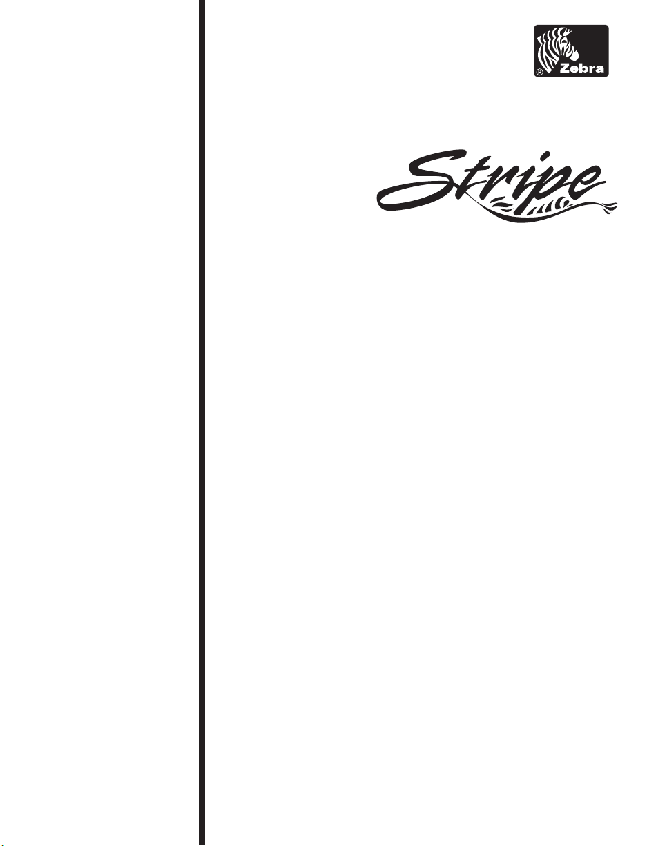
Introduction to Printers
The first thing you want to do is identify your printer. This makes certain
tasks -- such as media loading -- much easier to do!
If your printer
looks like this
(Figure 1), it is
set up for
Tear-Off mode.
Tear-Off allows
you to tear away
each label, or a
strip of labels,
after it is
printed.
To load media,
refer to
“Loading the
Media -Tear-Off Mode”
in Getting Ready
to Print.
Figure 1
Page 11
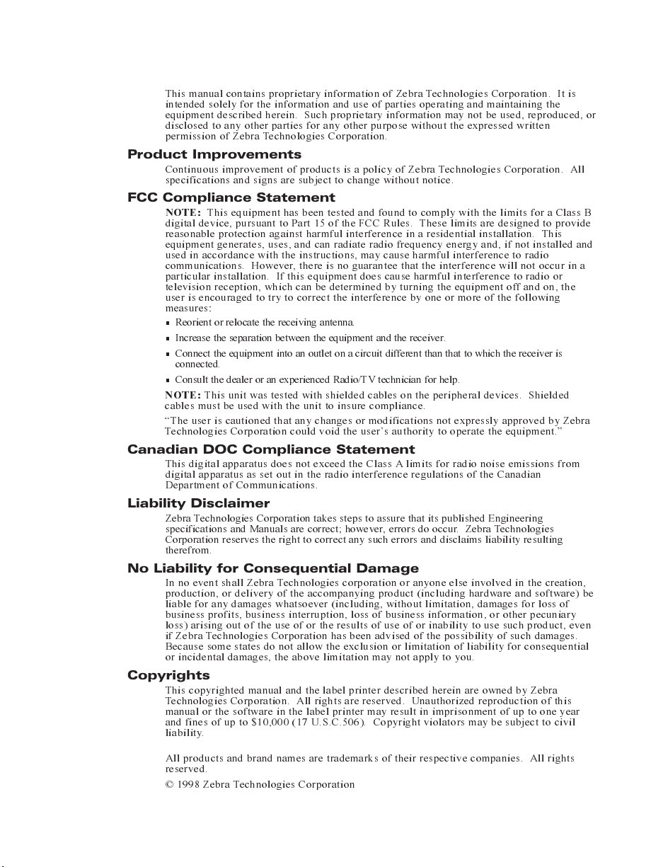
Figure 2
S400 & S600 User’s Guide 3
Backing
Rewind Spindle
This printer
(Figure 2)
operates in
Peel-Off mode.
In Peel-Off,
backing material
is peeled away
from the label as
it is printed.
After this label is
removed from the
printer, the next
one is printed.
To load media,
refer to “Loading
the Media -Peel-Off Mode”
in Getting Ready
to Print.
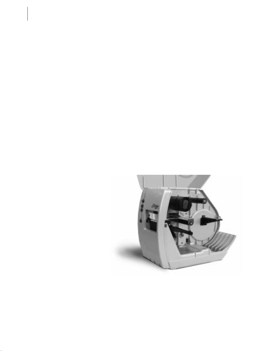
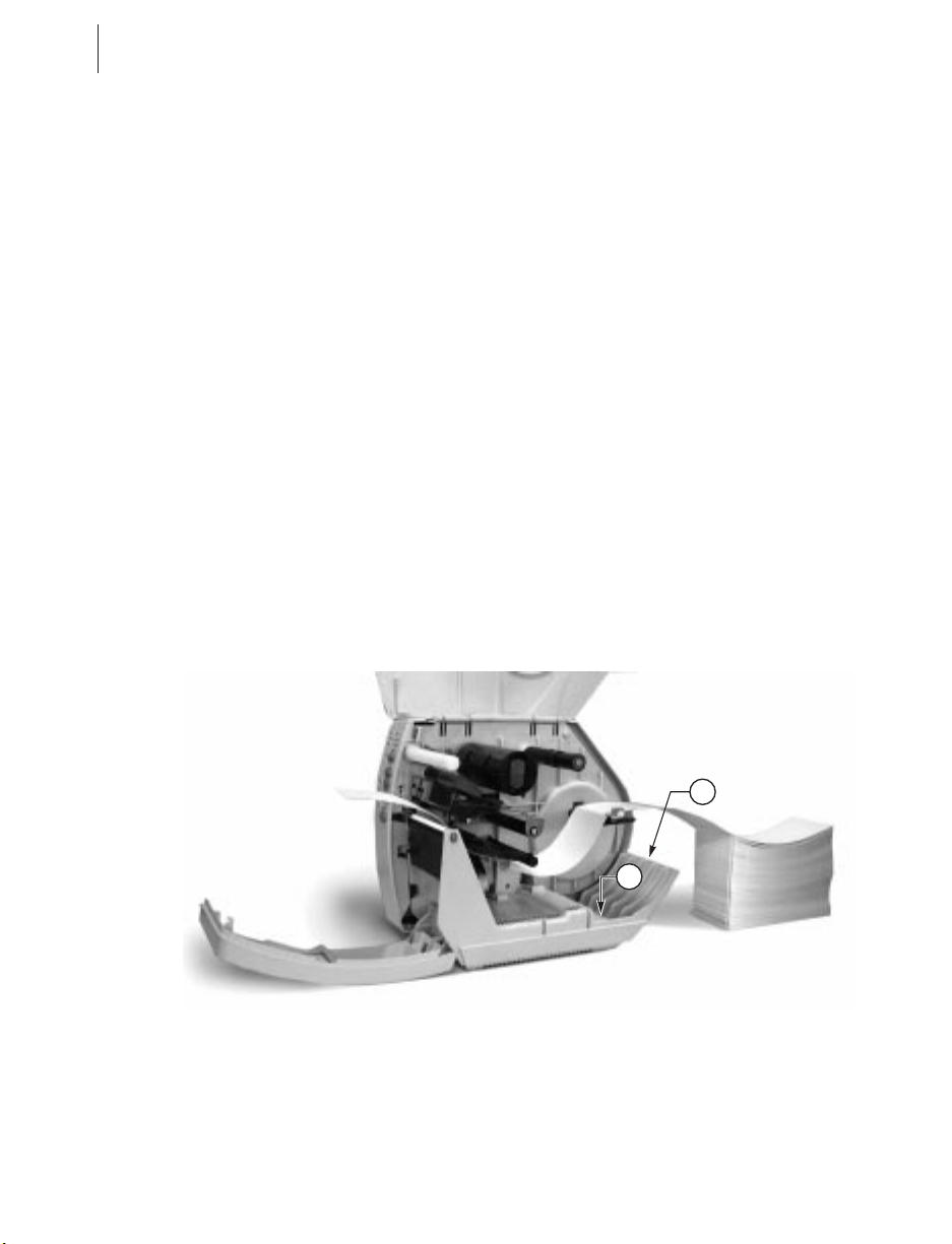
Cutter
Module
Printers like this
(Figure 3) are
equipped for
Cutter mode.
When in cutter
mode, the printer
automatically
cuts the label
after it is printed.
Then, the cutter
catch tray
“catches” the
label.
To load the
media, refer to
“Loading the
Media -- Cutter
Mode” in Getting
Ready to Print.
Figure 3
Page 12
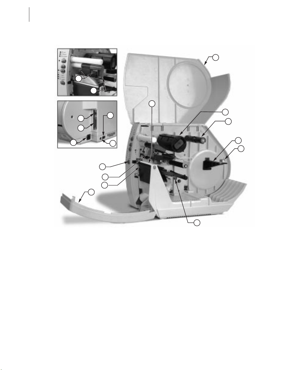
4 S400 & S600 User’s Guide
18
14
13
1
17
11
16
2
3
12
7
1
Media Access Cover
Ribbon Take-up Spindle
2
Ribbon Supply Spindle
3
Media Supply Hanger
4
Media Supply Guide
5
Media Guide
6
Front Cover
7
Tear Plate
8
Printhead
9
10
15
9
8
6
10
Control Panel
Platen Roller
11
AC Power Cable Connection
12
Parallel Interface
13
Serial Interface
14
Fuse
15
Power On/Off Switch
16
Head Open Lever
17
Pressure Toggles
18
4
5
Figure 4
Page 13
S400 & S600 User’s Guide 5
Getting Ready to Print
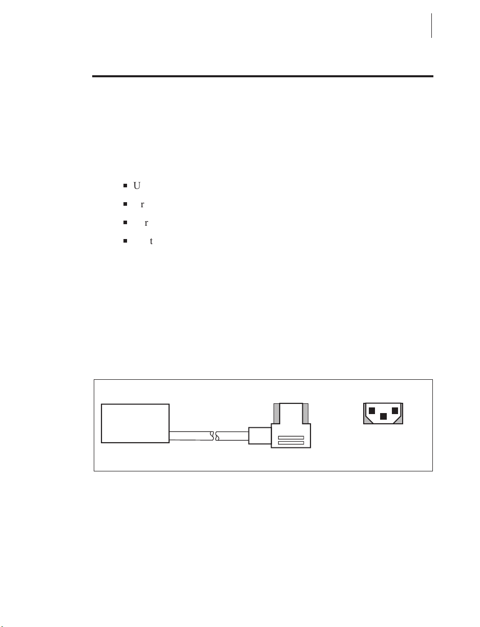
AC Power Cable
The AC power cable has a three-prong female connector on one end (see
Figure 5). This connector must be plugged into the mating connector on the
left side of the printer. See Figure 6.
The connector at the other end of the AC power cable will be one of the
following:
n
US Standard 110 VAC three-prong plug
n
Great Britain Standard 230 VAC three-prong plug
n
European Standard 230 VAC three-prong plug
n
Australian Standard 230 VAC three-prong plug
WARNING!!! For personnel and equipment safety, always use a
three-prong plug with an earth ground connection.
Insure that the AC power on/off switch is in the “off” position before
connecting the AC power cable to a nearby electrical outlet.
AC
POWER
CONNECTOR
3 CONDUCTOR
CABLE
NEUTRAL LIVE
EARTH
Figure 5
Page 14
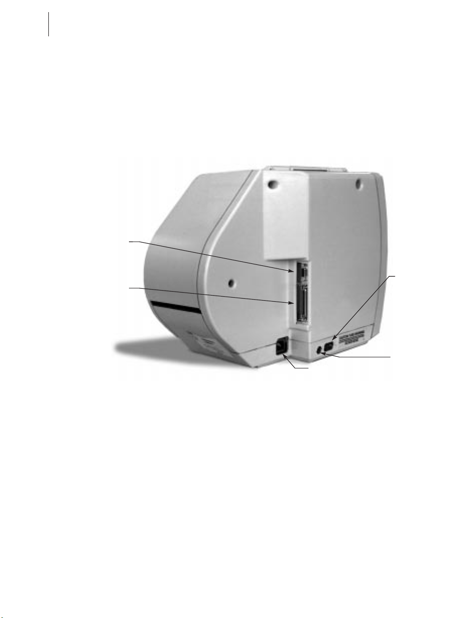
6 S400 & S600 User’s Guide
RS-232
(Serial)
Interface
Parallel
Interface
Power
On/Off
Switch
Figure 6
Fuse
AC Power Cable
Connection
Page 15
S400 & S600 User’s Guide 7
Loading the Media
Media widths and thicknesses vary between applications. To maintain print
quality from one application to another, refer to “Print Quality
Adjustments” in Routine Care and Adjustments.
NOTE: Zebra recommends using media that is outside wound (you can see
the labels on the outside of the roll).
Tear-Off Mode
1. Refer to Figure 7. Move the head open lever (a) counterclockwise to the
open position to raise the printhead (b).
2. Slide the media guide (c) and the media supply guide (d) as far out from
the printer frame as possible.
If you are loading roll media in Tear-Off mode, follow steps 3-5. For
loading fanfold media in Tear-Off mode, skip to step 6.
3. Place the media roll on the media supply hanger (e), and thread the me-
dia through the printhead assembly as shown.
b
a
d
e
c
Figure 7
Page 16
8 S400 & S600 User’s Guide
4. Adjust the media supply guide and the media guide against the outer
edge of the media. These guides must not cause pressure or excessive
drag on the media.
5. Close the head open lever, and see “Adjusting the Media Sensor” later in
this chapter to adjust the media sensor position.
For loading fanfold media:
6. Refer to Figure 8. Make sure the fanfold media feeds through either the
bottom (e) or rear (f) access slot.
NOTE: When utilizing the bottom access slot, be sure to thread media over
the media supply hanger.
7. Thread the media through the printhead as shown in Figure 8.
8. Adjust the media supply guide and the media guide against the outer
edge of the media. These guides must not cause pressure or excessive
drag on the media.
9. Close the head open lever, and see “Adjusting the Media Sensor” later in
this chapter to adjust the media sensor position.
Figure 8
f
e
Page 17
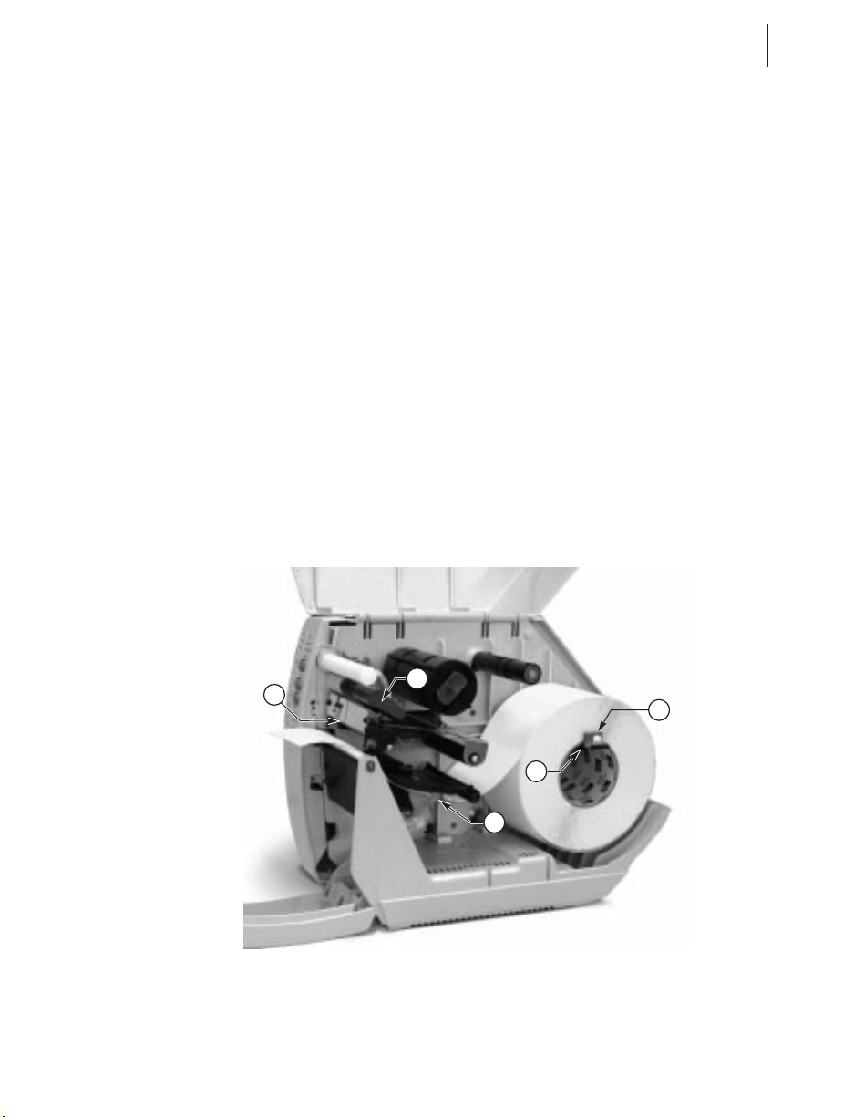
S400 & S600 User’s Guide 9
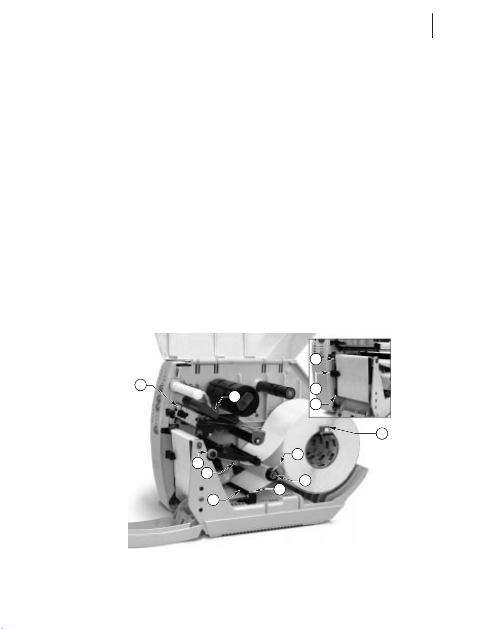
Peel-Off Mode (Optional)
Refer to Figure 9 and follow the procedure below.
1. Slide the media supply guide (a), media guide (b), and the outer edge
guides on both the platen guide rod (c) and the lower guide rod (d) as far
out from the printer frame as possible.
2. Open the head open lever (e) to raise the printhead (f).
3. Remove the hold down hook (g).
4. Thread the media through the printhead as shown in Figure 9.
5. From the front of the printer, pull the media through the printhead until
approximately 24" of media extends out from the printer. Remove the
labels from the backing of the 24" of media that extends from the front
of the printer.
6. Align the inside edge of the media with the edge guide mark (h) near the
left side of the tear-off/peel-off plate, then close the head open lever.
(See Figure 25 for a detailed illustration.)
7. Thread the label backing behind the lower label available sensor (i),
through the slot under the rewind power roller (j), and below the lower
guide rod (k) to the backing rewind spindle (l). Then, wind the backing
material around the backing rewind spindle three or four times in a
counterclockwise direction. To insure proper winding, press the edge of
the backing material against the round plate at the far end of the spindle.
h
f
e
c
b
d
k
Figure 9
i
j
a
g
l
Page 18
10 S400 & S600 User’s Guide
8. To hold the media against the spindle, place the hold down hook over
the backing and insert both ends into the small slots in the round plate at
the far end of the spindle. Again, rotate the backing rewind spindle
counterclockwise to remove any slack in the backing material.
9. Adjust all of the guides:
n
Push the media supply guide inward until it is just touching the outer
side of the media supply roll, then lock the guide in place with its
locking screw. The guide must not cause pressure or excessive drag on
the media supply roll.
n
Adjust the outer edge guides on both the lower guide rod and the platen
guide rod until they just touch the outer edge of the media and backing
without causing the material to buckle.
n
Adjust the media guide until it just touches the outer edge of the media
without causing the material to buckle.
10.See “Adjusting the Media Sensor” later in this chapter to adjust the me-
dia sensor.
NOTE: In the Peel-Off mode, proper media tracking is critical. Refer to
the “Backing Rewind Power Roller Adjustment” in Routine Care and
Adjustments to make sure that the media tracks properly through the
printer.
Removing the Label Backing Material
quired)
(Peel-Off Option Re-
When the amount of backing wound on the backing rewind spindle reaches
full capacity, the backing rewind spindle full sensor activates, the
paper/ribbon light flashes, and printing pauses.
To remove the backing material, follow these steps (you don’t need to
power off the printer for this procedure):
1. Unwind about 24" of backing from the backing rewind spindle and cut it
off at the spindle.
2. Pull out the hold down hook and slide the backing material off of the
spindle and discard.
3. Feed the new starting edge of the backing through the mechanism and
attach it to the backing rewind spindle as described in the loading procedure.
NOTE: While holding the media in position against the tear-off/peel-off
plate, open and close the printhead without disturbing the media position.
The printer is now ready to print more labels.
Page 19
S400 & S600 User’s Guide 11
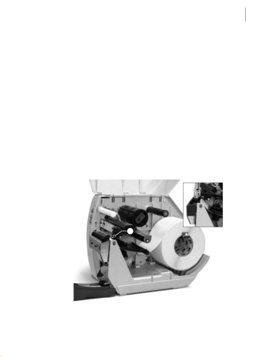
Cutter Mode (Optional)
To insure proper media loading, follow the directions for the Tear-Off
Mode with the exception that the end of the media must be positioned on
top of the platen roller. See Figure 10.
With the end of the media positioned directly on top of the platen roller (a),
close the head open lever. The printer will automatically calibrate, feed out,
and cut the label when the printer is powered on or the printhead is opened
and closed.
NOTES: The cutter only cuts if the printer is in cutter mode. Refer to the
ZPL II Programming Guide or the label preparation software user’s guide
for instructions.
The cutter will cycle once at power up or reset (even when NOT in cutter
mode).
a
Figure 10
Page 20
12 S400 & S600 User’s Guide
Loading the Ribbon
Before you load the ribbon, make sure the ribbon supply spindle is adjusted
properly.
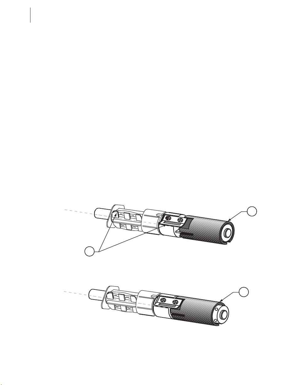
Ribbon Supply Spindle: Normal Position
In the normal position, the “dual-tension” ribbon supply spindle provides
the desired amount of ribbon back tension for different ribbon widths.
To place the spindle in the normal position, firmly pull the spindle end cap
(a) until it clicks into place, as shown in Figure 11.
Ribbon Supply Spindle: Low-Tension Position
Low-tension position is used in limited applications to provide lower ribbon
back tension. Low-tension position is only recommended when normal
tension hampers the ribbon movement (for example, you will see scuffing
or image breakup on the label).
To put the spindle in the low-tension position, firmly push the spindle end
cap (a) until it clicks into place, as shown in Figure 11.
Normal Position
a
b
Low-Tension Position
a
Figure 11
Page 21

S400 & S600 User’s Guide 13
Ribbon Loading Instructions
NOTES:
n
Zebra recommends the use of ribbon that is wider than the media. The
smooth backing of the ribbon protects the printhead from wear and
premature failure due to excessive abrasion. (For the direct thermal
print method, ribbon is not used and should not be loaded in the
printer.)
n
Zebra recommends the use of ribbon that is outside wound (the ink side
is on the outside of the roll).
To load ribbon, see Figure 12 and follow the procedure below.
1. Adjust the ribbon supply spindle position for normal or low tension.
2. Align the blades (b) on the two sections of the spindle as shown in
Figure 11. (You do not need to do this if your ribbon width is 2.4"
[60 mm] or less.)
3. Place the ribbon roll on the ribbon supply spindle (a). Make sure the roll
is pushed in to the stop at the end of the spindle.
4. Open the printhead by moving the head open lever (b) counterclockwise
to the open position.
5. Thread the ribbon as shown. Wind the ribbon onto the ribbon takeup
spindle (c) for several turns in a clockwise direction until wrinkles and
creases disappear.
6. Close the printhead by moving the lever clockwise to the closed posi-
tion.
Page 22
14 S400 & S600 User’s Guide
Ribbon Removal
Refer to Figure 12.
When it’s time to change the ribbon, cut the ribbon where it is stretched
between the upper ribbon guide arm and the takeup spindle. To remove
ribbon from the takeup spindle, press the release button (d) and slide the
ribbon off the spindle.
c
b
d
Figure 12
a
Page 23
S400 & S600 User’s Guide 15
Adjusting the Media Sensor
This adjustment aligns the position of the light sensor with the notch or
edge of the label, so the printer can determine the correct label size.
See Figure 13. With the printhead open, look through the side of the print
mechanism and locate the media sensor adjustment lever (a). Reposition
the sensor until the top of the adjustment lever is in line with the notch or
web in the media or the edge of the label. Close the printhead by moving
the head open lever to the closed position.
When continuous media (no notch or opening to sense) is used, position the
media sensor anywhere over the media so that an “out-of-media” condition
will still be sensed.
Non-Continuous Media
This type of media has some type of physical characteristic (web, notch,
perforation, etc.) that indicates the start/end of each label.
The media sensor must be properly positioned to sense these indicators.
See “Adjusting the Media Sensor” (above). Then, turn on the printer. If the
printer will not auto calibrate, press the MODE button three times, and then
the FEED button once, to manually calibrate (a label will print that shows
the sensor profile).
Continuous Media
Since continuous media does not contain label start/end indicators, you
must tell the printer via software how long each label is. If you are using
ZPL or ZPL II, include a Label Length (^LL) instruction in each label
format you send to the printer (refer to your ZPL II Programming Guide).
If you are using other software to operate your printer, refer to the
instructions provided with that software.
a
Figure 13
Page 24

16 S400 & S600 User’s Guide
Auto Calibration
This procedure occurs whenever the printer is turned on or the printhead is
opened and closed. During this procedure, the printer automatically
determines the media type, label length, media and ribbon sensor settings,
and printing method (direct thermal or thermal transfer). This procedure is
set at the factory but may be changed via ZPL II command.
NOTE: If the printer fails to auto calibrate when you are using pre-printed
labels or pre-printed label backing, or if the printer will not auto calibrate,
see “Manual Calibration” in Troubleshooting.
1. Load the media and ribbon (if used).
2. Turn on the printer power.
3. Two or three blank labels will feed, completing auto calibration.
Operator Controls
Front Panel Buttons
Refer to Figure 14.
PAUSE Button
n
Starts and stops the printing process.
n
The first time the button is pressed, any partially printed label is
completed; then, the printing process is stopped.
n
If the printer is idle when the button is pressed, no new print requests are
printed until PAUSE is pressed again.
FEED Button (also referred to as the UP button)
n
Forces the printer to feed one blank label.
n
If the button is pressed when the printer is idle or paused, a blank label
immediately feeds.
n
When the button is pressed while the printer is printing, one blank label
feeds after the completion of the current batch of labels.
n
Once the blank label has been fed, pressing the button again will feed a
second label.
n
When in the configuration mode, functions as the UP button.
CANCEL Button (also referred to as the DOWN button)
n
This button only functions when the printer is paused.
Page 25

n
If the button is pressed, the
label format that is currently
printing is canceled.
n
If pressed when no label format
is printing, then the next format
to be printed is canceled.
n
Press for at least three seconds
to cancel all label formats the
printer has received and return
the printer to an idle state.
n
When in the configuration
mode, functions as the DOWN
button.
S400 & S600 User’s Guide 17
POWER
PRINTHEAD
PAPER/RIBBON
PAUSE
MODE Button
n
Puts the printer into the
configuration mode.
n
Used to change print darkness
and media position, and to
calibrate the printer.
Front Panel LEDs
Refer to Figure 14.
The front panel LEDs give you a
quick indication of the printer’s
current status. During normal
operation, the POWER LED is on
and all other LEDs are off. For all
other conditions, please refer to
Troubleshooting.
Now, you’re ready to turn on the
printer!
FEED
DATA
CANCEL
DARKEN
POSITION
CALIBRATE
MODE
Figure 14
Page 26

18 S400 & S600 User’s Guide
AC Power ON/OFF Switch
This switch is located on the left side of the printer near the AC power cord
and fuse (see Figure 6). The AC power switch should be turned off before
connecting or disconnecting any cables.
Turning the switch on activates the printer and causes it to perform a Power
ON Self Test, which can take up to 30 seconds, as it begins operation.
Turning the printer power on while holding down certain front panel keys
will activate additional printer self tests following the Power ON Self Test.
See Troubleshooting.
External influences, such as lightning storms or unwanted noise on the
power or data cables, may cause erratic printer behavior. Turning the AC
power off and back on may re-establish proper printer operation.
Otherwise, see Troubleshooting.
Printing a Test Label
Before you connect the printer to your computer, make sure that the printer
is in proper working order. You can do this by printing a configuration
label (refer to the “CANCEL Key Self Test” in Troubleshooting.) If you
can’t get this label to print, refer to Troubleshooting.
To make print quality adjustments, refer to “Print Quality Adjustments” in
Routine Care and Adjustments.
Connecting the Printer and Computer
This printer comes with both a nine-pin Electronics Industries Association
(EIA) RS-232 serial data interface and an IEEE 1284 bi-directional parallel
data interface. In either case, you must supply the required interface cable
for your application.
CAUTION: This printer complies with FCC “Rules and Regulations,”
Part 15, for Class B Equipment, using fully shielded six-foot data cables.
Use of longer cables or unshielded cables may increase radiated emissions above the Class B limits.
RS-232 Interface Requirements
Refer to Figure 6.
The required cable must have a 9-pin “D” type (DB-9P) connector (male)
on one end, which is plugged into the mating (DB-9S) connector (female)
located inside the access opening on the left side of the printer.
The other end of the signal interface cable connects to a serial port at the
host computer. This cable will be one of two types -- standard or null
modem -- depending on the specific interface requirements.
Page 27

S400 & S600 User’s Guide 19
For pinout information, as well as information on how to interconnect to
either a DTE or DCE device, refer to the Appendix.
Parallel Interface Requirements
Refer to Figure 6.
An IEEE 1284 compatible bi-directional parallel data cable is required
when this communication method is selected. The required cable must have
a standard 36-pin parallel connector on one end, which is plugged into the
mating connector located inside the access opening on the left side of the
printer. The parallel interface cable is connected using bail clips instead of
screws.
The other end of the parallel interface cable connects to the printer
connector at the host computer.
For pinout information, refer to the Appendix.
Serial and Parallel Cabling Requirements
Data cables must be fully shielded and fitted with metal or metallized
connector shells. Shielded cables and connectors are required to prevent
radiation and reception of electrical noise.
To minimize electrical noise pickup in the cable:
1. Keep data cables as short as possible.
2. Do not bundle the data cables tightly with power cords.
3. Do not tie the data cables to power wire conduits.
Communicating with the Printer
Via the Parallel Port
n
Set the parallel connection on the host computer. For instructions, refer
to your computer’s user’s guide.
Via the Serial Port
n
Set the host computer to the factory defaults of the printer: 9600 baud, 8
bit word length, no parity, 1 stop bit, and XON/XOFF. For instructions,
refer to your computer’s user’s guide.
NOTE: If you can’t reset the host computer communications settings, then
you must establish a temporary parallel connection to send down the Set
Communications (^SC) command that changes the printer’s settings to
match the host settings.
DEFAULTING THE PRINTER: To reset only the communications
parameters on the printer to the factory defaults (9600 baud, 8 bit word
Page 28

20 S400 & S600 User’s Guide
length, no parity, 1 stop bit, and XON/XOFF), press and hold the PAUSE,
FEED, and MODE buttons while turning on the printer, then release the
buttons when the CALIBRATE LED goes out. All of the LEDs will go on,
while the DARKEN, POSITION, and CALIBRATE LEDs will flash. Press
and hold the MODE button until all of the lights go out, then release the
MODE button. The factory defaults have now been reset. Next, set the
communications parameters on your computer to match this.
NOTE: To save the default settings, press the MODE button four times.
Otherwise, the previous settings will be restored the next time the printer is
turned on.
AUTOBAUD: To automatically detect the communications parameters,
press and hold the PAUSE, FEED, and MODE buttons while turning on the
printer, then release the buttons when the CALIBRATE LED goes out. All
of the LEDs will go on, while DARKEN, POSITION, and CALIBRATE
LEDs will flash. Send a label format using the host computer settings. If
the printer accepts the host parameters, all of the LEDs will go off (except
for the POWER LED) and the printer will restart with the host
communication settings. If the printer does not accept the host
communications parameters, the printer will not restart and the LEDs will
flash on and off. If this should happen, turn the printer off and then on, and
try again.
NOTES: Label formats sent to the printer at this time only help the printer
determine the host settings. No label will print until settings are recognized.
In order for autobaud to work, your label must start with either a ^XA or
~XA ZPL II command. If all the LEDs are on, send another label format.
Save the new communication settings by pressing MODE four times.
Autobaud only works for 9600 baud and higher.
^SC: Use the Set Communications (^SC) command to change the
communications settings on the printer. 1) With the host computer set at
the same communications settings as the printer, send the ^SC command to
change the printer to the desired settings. 2) Then, change the host
computer settings to match the printer settings.
Setting Up the Software
In order to create labels, you must decide whether you will use ZPL II or
commercial label preparation software. To use ZPL II, refer to the ZPL II
Programming Guide. If you choose to use a label preparation software,
follow the installation instructions included in the package.
Page 29

S400 & S600 User’s Guide 21
Routine Care and Adjustments
Cleaning
CAUTION: Use only the cleaning agents indicated below. Zebra
Technologies Corporation will not be responsible for any other products being used on this printer. No lubricants are needed.
The following table provides a brief cleaning schedule. Specific cleaning
procedures are provided on the following pages. Cleaning swabs saturated
with 70% isopropyl alcohol are available from your distributor as a
preventive maintenance kit.
Refer to Figure 15 for cleaning locations.
Printhead (a) Alcohol
Platen roller (b) Alcohol
Media sensor (c) Air blow
Media path (d) Alcohol
Ribbon path (e) Air blow
Upper guide rod (f) (Peel-Off) Alcohol
Platen guide rod (g) (Peel-Off) Alcohol
Rewind power roller (h) (Peel-Off) Alcohol
Lower guide rod (i) (Peel-Off) Alcohol
Cutter
Assembly
(j)
(if used)
Tear-Off/Peel-Off plate (k) Alcohol Once a month.
Label available sensor (l) Air blow Once every six months.
Area Method Interval
After every roll of media (or 500
feet of fanfold media) when
printing in the direct thermal
mode.
After every roll of ribbon when
printing in the thermal transfer
mode.
Cutting
continuous,
pressuresensitive media
Cutting tagstock
or label backing
material only
Citrus
based
adhesive
remover
Alcohol and
air blow
After every roll of media or more
often, depending upon your
application and media.
After every 2 or 3 rolls of media.
Page 30

22 S400 & S600 User’s Guide
e
c
d
h
j
g
l
a
b
i
f
k
Figure 15
Page 31

S400 & S600 User’s Guide 23
Cleaning the Exterior
The exterior surfaces of the printer may be cleaned with a lint-free cloth.
Do not use harsh or abrasive cleaning agents or solvents. If necessary, a
mild detergent solution or desktop cleaner may be used sparingly.
Cleaning the Interior
Remove any accumulated dirt and lint from the interior of the printer using
a soft bristle brush and/or vacuum cleaner. Inspect this area after every roll
of media.
Cleaning the Printhead and Platen Roller
Inconsistent print quality, such as voids in the bar code or graphics, may
indicate a dirty printhead. For optimum performance, perform the
following cleaning procedure after every roll of ribbon.
NOTE: It is not necessary to turn the printer off before cleaning the
printhead. If power is turned off, all label formats and images, as well as
any temporarily saved parameter settings stored in the printer’s DRAM
memory, will be lost. When power is turned back on, it will be necessary to
reload these items.
To clean the printhead, refer to Figure 16 and follow these steps:
1. Open the media access cover and the front cover (see Figure 4).
b
c
d
Figure 16
a
Page 32

24 S400 & S600 User’s Guide
2. Open the printhead (a) by moving the head open lever (b) to the open
position.
3. Remove the media and ribbon (if present).
4. With a swab, wipe the print elements (c) from end to end (the print ele-
ments are the grayish/black strip just behind the chrome strip.) Allow a
few seconds for the solvent to evaporate.
5. Rotate the platen roller (d) and clean thoroughly with alcohol.
6. Brush/vacuum any accumulated paper lint and dust away from the roll-
ers and media sensors.
7. Reload ribbon and/or media, close and latch the printhead, close the
front cover and the media access cover, and continue printing.
If print quality has not improved after performing this procedure, try
cleaning the printhead with Save-a-Printhead cleaning film. This specially
coated material removes contamination buildup without damaging the
printhead. Call your authorized Zebra distributor for more information.
Cleaning the Cutter Module (for Printers
Equipped with the Optional Cutter)
The cutter module requires periodic cleaning to remove paper dust and
gummed label residue. The procedure on the following pages should be
performed by the operator according to the cleaning schedule table.
However, depending on your application and media type, you may need to
clean the cutter more or less frequently.
NOTE: In the figures shown, media and ribbon have been removed for
clarity. It is not necessary to remove media or ribbon before performing the
maintenance procedures described.
IMPORTANT: Do not exchange cutter modules between different
printers. The cutter module adjustments are optimized during installation to
work with a particular printer and may not perform correctly if the module
is placed on a different printer.
I. Removing the cutter module from the printer.
1.
Turn off the printer’s AC power.
See Figure 17. Remove the label catch tray (a) by lifting it up and away from
2.
the front of the cutter module (b).
3.
Raise the printer’s media access cover and lower the printer’s front cover.
See Figure 18. Gently pull straight down on the cutter cable connector (a) to
4.
remove it from the mating socket on the cutter module.
Turn the cutter mounting screw (b) with a screwdriver or by hand in a
5.
counterclockwise direction until it is loose.
See Figure 19. Hold the cutter module as shown. Apply gentle upward pressure to
6.
the left and right ends while raising the cutter module up and away from the
mounting posts (a). If necessary, rock the module side to side to loosen it.
Page 33

S400 & S600 User’s Guide 25
b
a
Figure 17
b
a
Figure 18
Page 34

26 S400 & S600 User’s Guide
a
b
Figure 19
a
Figure 20
c
b
a
Page 35

S400 & S600 User’s Guide 27
II. Disassembling the cutter module.
See Figure 20. Hold the cutter module as illustrated. Put your thumbs on the
two wire spring loops (a) and your index fingers on the top of the rear cutter
1.
blade guard (b). It may help to lay the cutter module on a table or other
surface throughout this process.
To remove the rear cutter blade guard, first press down simultaneously on the
two wire spring loops. While pressing down on the loops, press the rear
2.
cutter blade guard back toward you and over the top of the loops. (You’re
trying to tuck the loops underneath the blade guard in this process.)
Continue pressing the rear cutter blade guard toward you and allow the back
edge of the guard to pop up as the guard comes free from its holders. You
3.
may now remove the rear cutter blade guard by lifting it off of the module.
NOTE: The wire springs may flip up out of position during this process.
Springs will be repositioned during reassembly.
Observe the ends of the rear cutter blade guard and note the small metal pins
protruding toward the inside. During the reassembly procedure, these pins
4.
will be mounted into the corresponding mounting slots in the cutter side
panels.
To provide complete access to the area to be cleaned, raise the upper cutter
5.
blade guard (c) as shown in Figure 20.
III. Cleaning the cutter module.
Remove any label material which has adhered to the cutter parts and use a
1.
small brush to remove any paper dust from the cutter module.
If you use pressure-sensitive media, use a lint-free cloth soaked in an adhesive
remover to remove all gum and label residue from the cutting blades and
2.
guards.
If you use tag stock, use alcohol to remove any dirt.
IV. Reassembling the cutter module.
See Figure 21. Position the two wire springs (a) down against the lower cutter
1.
blade.
Place the rear cutter blade guard (b) over the wire springs, perpendicular to its
final position. Place your thumbs on the top (flat) part of the guard.
2.
NOTE: Insure that the ends of the rear cutter blade guard are positioned on the
outside of the cutter side panels.
Press the rear cutter blade guard down and forward, rotating the guard as you
proceed, to lock the mounting pins (c) into position in the cutter side panel
mounting slots (d). Slide the guard forward until the two wire spring loops
3.
pop up on the back side of the Guard.
NOTE: Insure that the wire springs remain positioned under the rear cutter blade
guard when assembly is completed.
Lower the upper cutter blade guard back to its normal position. When
4.
reassembled, the back of the cutter module should look like the one shown in
Figure 22.
Page 36

28 S400 & S600 User’s Guide
a
b
a
b
c
d
a
b
a
CUTTER
SIDE PANEL
Figure 21
Figure 22
CUTTER
SIDE PANEL
Page 37

S400 & S600 User’s Guide 29
V. Reinstalling the cutter module.
See Figure 19. Position the cutter module above the cutter mounting posts (a).
1.
Press down on the cutter module until the mounting slots (b) engage the
mounting posts on the printer.
See Figure 18. Tighten the mounting screw (b) in a clockwise direction to
2.
hold the cutter module in position.
See Figure 18. Position the cutter cable connector (a) so the flat side of the
3.
connector faces away from the printer, then insert it up into the mating
connector on the cutter module.
Replace the cutter catch tray onto the two mounting posts located on the
4.
front of the cutter module.
VI. Testing the Cutter Operation.
If necessary, reload ribbon and label stock into the printer, then close the
printer’s front cover and media access cover.
1.
NOTE: When loading media, make sure the end of the label is positioned on
top of the platen roller, then close the printhead open lever.
When the printer is turned on, the cutter module will cycle through one cutting
2.
operation and be ready to print labels.
OPTIONAL: Hold in the PAUSE button while turning on the printer’s AC power.
When the Power ON Self Test begins (all LEDs on), release the PAUSE button.
3.
When the Power ON Self Test ends, the printer will automatically print test labels
that the cutter module will automatically cut.
End of the cutter cleaning procedure.
Page 38

30 S400 & S600 User’s Guide
Lubrication
No lubricating agents of any kind are required on this printer. Some
commercially available lubricants will damage the finish if used.
AC Power Fuse Replacement
A user-replaceable AC power fuse (see Figure 6) is located just to the left of
the power on/off switch. For use with both voltage ranges, the replacement
fuse is a 5x20 fast blow style rated at 5 Amp/250 VAC.
1. Before replacing the fuse, turn the AC power switch off and unplug the
AC power cable.
2. To replace the fuse, insert the tip of a flathead screwdriver into the slot
in the end of the fuse holder end cap.
3. Press in slightly on the end cap and turn the screwdriver slightly counterclockwise. This will disengage the end cap from the fuse holder and
permit the removal of the fuse.
4. To install a new fuse, reverse the procedure.
Page 39

S400 & S600 User’s Guide 31
Mechanical Adjustments
This printer has been designed with minimal operator adjustments required.
Print Quality Adjustments
When changing from one media/ribbon combination to another, only slight
changes in print darkness or toggle pressure may be required. For these
situations, refer to the toggle pressure adjustment in this chapter.
I. Checking the initial print quality.
Open the media access cover and front cover on the printer (see
1.
Figure 4).
Load the recommended media and ribbon for your application and adjust the
2.
media sensor position.
Send a label format to the printer or activate the PAUSE key self test (see
3.
Troubleshooting), print a few labels, and press the PAUSE button to stop
printing.
Observe the print quality of the test labels. If it is satisfactory, exit the PAUSE
4.
key self test by pressing and holding the CANCEL button until the DATA LED
goes off. Otherwise, continue to step II.
II. Adjusting the print darkness (burn temperature).
Press the MODE button once (DARKEN and PAUSE LEDs turn on) to permit
1.
darkness adjustment.
2.
Press the PAUSE button to begin printing test labels.
While observing the print darkness, repeatedly press the UP (FEED) button to
3.
make the printing darker, or the DOWN (CANCEL) button to make the printing
lighter, until the desired darkness is achieved.
Briefly press the MODE button three times. The MODE LEDs will flash on and
4.
off to indicate that the settings have been saved in memory.
5.
Press the PAUSE button to stop printing.
NOTE: To confirm the change, turn off the printer. Then, turn on the printer
while holding the CANCEL button.
If you are still experiencing poor print quality, perform the following toggle
pressure adjustment. Otherwise, exit the PAUSE key self test by pressing
and holding the CANCEL button until the DATA LED goes off.
Toggle Pressure Adjustment
The toggle assembly presses the printhead against the ribbon (if used), the
media, and the platen.
Page 40

32 S400 & S600 User’s Guide
The pressure applied by the toggle assembly may need to be increased or
reduced when different thicknesses or widths of media are used in the
printer.
NOTE: Before increasing toggle pressure to achieve darker print darkness,
perform the print quality adjustments.
Refer to Figure 23. Turn the two knurled toggle pressure adjust knobs (a)
on top of the toggle assembly to adjust the pressure. Turning clockwise will
increase the pressure, and turning counterclockwise will decrease the
pressure.
Always use the lowest toggle pressure necessary to provide the desired print
darkness on the label.
NOTE: When using media narrower than 4.5" wide (full media width),
reduce the pressure on the right hand toggle until print quality is affected,
then increase pressure just to the point where good print quality is achieved.
This reduces the wear on those areas of the printhead and the platen where
ribbon and media are not present. (For very narrow media, zero pressure
from the right toggle may be required.)
a
Figure 23
Right
Toggle
Page 41

S400 & S600 User’s Guide 33
Media Rest Position Adjustment
This procedure sets the end-of-label position relative to the Tear-Off plate
or cutter. Adjust this if your label is not being torn or cut at the correct
point.
1. Briefly press the MODE button twice. The PAUSE and POSITION
LEDs turn on.
2. Press UP (FEED) or DOWN (CANCEL) to adjust the current setting.
3. Briefly press the MODE button twice. The MODE LEDs will flash on and
off to indicate that the settings have been saved in memory.
4. Press PAUSE to exit the pause mode. The PAUSE LED turns off.
Top of the Label Position Adjustment
This procedure positions the printing on the label relative to the top edge of
the label. Adjust this if your printing is too close or too far away from the
top or bottom edge of the label.
1. Briefly press the MODE button twice, then press and hold it for about
five seconds until the lights change. The PAUSE, DARKEN, and
CALIBRATE LEDs turn on.
2. Press UP (FEED) or DOWN (CANCEL) to adjust the current setting.
3. Briefly press the MODE button twice. The MODE LEDs will flash on
and off to indicate that the settings have been saved in memory.
4. Press PAUSE to exit the pause mode. The PAUSE LED turns off.
Media Sensor Position Adjustment
This procedure is covered in Getting Ready to Print.
Ribbon Supply Spindle Adjustment
This procedure is covered in Getting Ready to Print.
Page 42

34 S400 & S600 User’s Guide
Backing Rewind Power Roller Adjustment
(PEEL-OFF OPTION REQUIRED)
NOTE: This roller is only present on printers with the Peel-Off option.
Zebra presets this roller during manufacture for proper operation with most
applications. Only adjust this roller when necessary.
In the Peel-Off mode, proper media tracking is critical. The rewind power
roller automatically turns along with the movement of media, to insure
continuous rewind of the label backing material. When adjusting this roller,
the operating position may vary due to the type, width, and thickness of the
backing material.
Before performing this adjustment, review the media loading procedure in
Getting Ready to Print. Insure minimal sideways movement during the
printing process by positioning the left edge of the label backing even with
the edge guide mark on the tear-off/peel-off plate. Position the media
guides against the outside (right) edge of the media, but not so tight as to
bind the material.
When the power roller is properly adjusted, the backing material should
have even tension across its entire width and be wrapped snugly around all
guides and rollers. If the tension is not even, the media/backing material
may slide (walk) to the left or to the right as printing occurs. This can cause
print registration problems on the labels.
Left
Edge
Right
Edge
b
d
Figure 24
Up
a
c
Down
e
Page 43

S400 & S600 User’s Guide 35
Figure 24 illustrates an improperly adjusted backing rewind power
roller (a). On the left side, the backing material (b) is not contacting the
power roller. The backing has more tension on the right edge (c) than on
the left edge (d).
Use a coin or screwdriver to turn the power roller adjustment (e). The
adjustment mechanism changes the position of the right end of the roller,
while the left end is stationary. The right end moves up and down for
tension balance.
Turning this adjustment in a counterclockwise direction causes the right end
of the power roller to move down and increases the tension on the right side
of the backing material. (Turning the adjustment in a clockwise direction
moves the right end of the power roller up and decreases the tension on the
right side.)
Balancing the tension increases the reliability of the printer to provide
properly printed labels by preventing the label backing from walking.
Use the FEED key self test (see Troubleshooting) or your own label format
to print several labels to insure tracking is maintained and tension on both
edges of the backing material remains consistent. Remember to remove
each label as it is automatically peeled away from the backing.
Page 44

36 S400 & S600 User’s Guide
Page 45

S400 & S600 User’s Guide 37
Troubleshooting
If the printer operates in an abnormal fashion, consult the troubleshooting
table below. The printer diagnostics following the troubleshooting table
may also help you to determine the problem.
The troubleshooting of some problems may be beyond the abilities of the
operator. In these cases, call a service technician to perform additional
troubleshooting and repair procedures.
Troubleshooting Table
Symptom Diagnosis Action
No LEDs turn on.
Printer locks up with all
LEDs on when running
the Power-on self test.
CALIBRATE LED is off but
all other LEDs are on.
CALIBRATE and
POSITION LEDs off but
all other LEDs on.
CALIBRATE, POSITION,
and DARKEN LEDs off
but all other LEDs on.
CALIBRATE, POSITION,
DARKEN, and DATA
LEDs off but all other
LEDs on.
CALIBRATE, POSITION,
DARKEN, DATA, and
PAUSE LEDs off but all
other LEDs on.
No AC power
applied to the
printer.
Faulty AC power
fuse.
No voltage
available from the
internal power
supply.
Hardware failure. Call a service technician.
Boot-block CRC
error.
DRAM error. Call a service technician.
Firmware
decompression
error.
Firmware error.
Firmware error.
Insure the AC power cable is
connected to a working voltage
source.
Replace the fuse.
Call a service technician.
Call a service technician.
Call a service technician for
instructions on how to download
and install firmware.
Page 46

38 S400 & S600 User’s Guide
Symptom Diagnosis Action
Printer stops, PAUSE LED
and PAPER/RIBBON LED
both on.
Printer stops, PAUSE
LED on and PAPER/
RIBBON LED flashing.
Printer stops, PAUSE
LED on and PRINTHEAD
LED flashing.
Printer stops, PAUSE
LED and PRINTHEAD
LED both on.
Printer will not
successfully perform an
auto calibration.
Printer will not perform a
manual calibration.
Printing continues,
PRINTHEAD LED on.
PAUSE LED flashing.
Media incorrectly
or not loaded.
Cutter error.
Calibration error. Re-calibrate printer.
Misadjusted
media sensor.
Are you using
pre-printed
media?
Ribbon
incorrectly or not
loaded.
Backing rewind
spindle is full.
Malfunctioning
ribbon sensor.
Ribbon not
calibrated.
Printhead is not
fully closed.
Printhead open
sensor not
detecting its
position flag.
Printhead
element is
overheated.
Power supply
over temperature.
Printhead open. Close the printhead.
You’re using
pre-printed
labels.
Media is out.
Media is out of
specification.
Hardware failure. Call a service technician.
Printhead is
under
temperature.
Waiting for user
to peel label.
Load media correctly, then turn the
printer off and on. See Getting
Ready to Print.
Clear jam, then open and close the
printhead.
Check position and sensitivity of
media sensor. See Getting Ready
to Print.
Calibrate the printer. Refer to
Getting Ready to Print.
Load ribbon correctly, then turn the
printer off and on. See Getting Ready
to Print.
Remove label backing from the
spindle.
Call a service technician.
Calibrate the ribbon. Refer to
“Resetting Ribbon Parameters”
later in this chapter.
Close printhead completely, then
turn the printer off and on.
Call a service technician.
Printer resumes printing when the
printhead element cools.
Printer resumes printing when the
power supply cools.
Perform a manual calibration. See
“Manual Calibration” later in this
chapter.
Load media. Ensure that the media
sensor is properly positioned.
Ensusre that the media sensor is
properly positioned. Or, perform a
manual calibration. See “Manual
Calibration” later in this chapter.
Continue printing.
Remove label.
Page 47

Symptom Diagnosis Action
DATA LED is single
flashing.
PAUSE LED and DATA
LED alternately flashing,
but all other LEDs on.
DATA LED is flashing.
DATA LED is slow
flashing.
Dots missing in printed
area of label.
Loss of printing
registration on labels.
For Peel-Off mode:
Excessive vertical drift in
top-of-form registration.
Light vertical lines
approximately .006 wide
running through all
labels.
Light printing or no
printing on the left or
right side of the label.
Short printed lines at 45°
to label edge on left or
right side of label.
CANCEL button
was pressed and
a format was
deleted.
Firmware error.
Printer is
receiving data.
Printer sent a
“stop
transmitting” to
the host
computer.
Dirty printhead.
Printhead
element going
bad. Print quality
problems.
Print width set
incorrectly.
Possible media
sensor problem.
Printer set for
non-continuous
media, but
continuous media
loaded.
Improperly
adjusted media
edge guides or
power roller.
Incorrect media
loading or media
sensor
adjustments.
Dirty head or
ribbon rollers.
Defective printhead
elements.
Printhead needs
balancing.
Too much
printhead
pressure.
No action required.
Call a service technician for
instructions on how to download
and install firmware.
Printing resumes when data is
received.
No action required.
Clean the printhead. See Routine
Care and Adjustments.
Call a service technician.
Default the printer. Refer to
“Resetting Factory Defaults” later in
this chapter.
Adjust media sensor position and
call a service technician if
necessary.
Set printer for correct media. See
Getting Ready to Print.
Refer to Getting Ready to Print and
Routine Care and Adjustments for
proper positioning and
adjustments.
See “Loading the Media” or
“Adjusting the Media Sensor” in
Getting Ready to Print.
See “Printhead Cleaning” in
Routine Care and Adjustments.
Call a service technician.
Adjust balance. See “Toggle
Pressure Adjustment” in Routine
Care and Adjustments.
Reduce the pressure. See “Toggle
Pressure Adjustment” in Routine
Care and Adjustments.
S400 & S600 User’s Guide 39
Page 48

40 S400 & S600 User’s Guide
Symptom Diagnosis Action
Truncated print, no
print, or FEED button
operates incorrectly
while using
non-continuous media.
Fine gray lines on blank
labels at angles.
Long tracks of missing
print on several labels.
Wrinkled ribbon.
In Peel-Off mode,
skewed or stuck labels.
Image is not positioned
correctly and/or misprint
of 1 to 3 labels.
Media or ribbon
improperly
loaded.
Incorrect media
sensor position or
sensitivity.
Wrinkled ribbon. See “Wrinkled Ribbon” in this table.
Wrinkled ribbon. See “Wrinkled Ribbon” in this table.
Print element
damaged.
Ribbon fed
through machine
incorrectly.
Incorrect
darkness setting.
Incorrect
printhead
pressure.
Incorrect
dual-tension
spindle setting.
Media not feeding
properly; it is
walking from side
to side.
Continuing
symptoms.
Glue material
from back of
labels causing
media movement
problems.
Media and
backing not
properly aligned
in printer.
Media was pulled
when motor was
not moving.
Incorrect media
sensor position.
Media or ribbon
improperly
loaded.
Auto calibrate
failed.
See “Loading the Media” and
“Loading the Ribbon” in Getting
Ready to Print.
See “Adjusting the Media Sensor”
in Getting Ready to Print.
Calibrate. See “Auto Calibration” in
Getting Ready to Print.
Call a service technician.
See ribbon loading in Getting
Ready to Print.
Set to the lowest value needed for
good print quality.
See “Toggle Pressure Adjustment”
in Routine Care and Adjustments.
Pull spindle end cap out when
using wide media to obtain normal
(higher) tension. See “Loading the
Ribbon” in Getting Ready to Print.
Make sure the media is snug by
adjusting the media guides.
Call a service technician.
Refer to Routine Care and
Adjustments and perform
maintenance and cleaning of the
printer.
Refer to Getting Ready to Print and
Routine Care and Adjustments;
reload media and adjust the power
roller, if needed.
Open and close the printhead, so it
calibrates to find the label length.
See “Adjusting the Media Sensor
Position” in Getting Ready to Print.
See “Loading the Media” and
“Loading the Ribbon” in Getting
Ready to Print.
Perform a manual calibration. See
“Manual Calibration” later in this
chapter.
Page 49

Symptom Diagnosis Action
Reload the factory defaults (see
“FEED Key and PAUSE Key” later in
this chapter), calibrate the printer,
then cycle the power on/off switch.
Call a service technician.
See “Loading the Ribbon” in
Getting Ready to Print to adjust the
ribbon supply spindle to provide
low tension.
Print configuration label and verify
that the host computer and printer
settings match. If they do, perform
the MODE key self test and check
for format or overrun errors. If
they do not, refer to
“Communicating with the Printer”
in Getting Ready to Print.
Set the characters in the printer to
match the ZPL format.
Check configuration printout for
correct characters.
If problem continues, check the
ZPL format for changed ^CC,
^CT, and ^CD instructions.
Changes in parameter
settings did not take
effect.
When using wide ribbon
(over 2.4"), the image
gets lighter or smears
near the end of the roll
of ribbon. Ribbon
appears to slow down or
stop.
ZPL was sent to printer,
but not recognized. The
DATA LED remains off.
Parameters are set
or saved
incorrectly.
If problem
continues, there
may be a
problem on the
main logic board.
Too much
back-tension on
the ribbon.
Communications
parameters are
set incorrectly.
Prefix and
delimiter
characters set in
printer
configuration do
not match the
ones sent in the
ZPL label formats.
S400 & S600 User’s Guide 41
Page 50

42 S400 & S600 User’s Guide
In cutter mode, skewed,
stuck, improperly cut or
partially cut labels.
The cutter is jamming
up with labels, or labels
are being cut more than
once.
Labels are not being cut
at all.
Printing stops,
PAPER/RIBBON, PAUSE,
and CANCEL LEDs on.
For printers with the
cutter option installed.
Cutter is dirty.
Cutter blades are
dull.
Cutter is dirty.
Label length is
too short.
Cutter option not
enabled.
Connecting cable
not connected to
cutter module.
Out of media. Load media.
Media jammed in
cutter.
Cutter module is
dirty.
End of the media
not positioned
correctly on top of
platen.
If error condition persists after attempting each of the
above solutions, call a service technician.
Follow cutter cleaning procedure in
Routine Care and Adjustments.
Call a service technician.
Follow cutter cleaning procedure in
Routine Care and Adjustments.
Increase label length.
See Routine Care and
Adjustments.
With printer power off, plug cable
into cutter module.
Remove media, clean cutter
module if necessary.
Clean cutter module. See Routine
Care and Adjustments.
Reposition media so that the end is
on top of the platen. See Getting
Ready to Print.
Page 51

S400 & S600 User’s Guide 43
Printer Status Sensors
The printer contains several status sensors. These sensors alert the operator
to various conditions by either stopping the printing or turning on an LED.
Sensor What it Monitors How it Works
Printhead
sensor
Media sensor
(See Getting
Ready to Print
to adjust this
sensor.)
Ribbon sensor
Label available
sensor (PeelOff option
required. See
Figure 25.)
Backing rewind
spindle full
sensor (PeelOff option
required. See
Figure 26.)
Checks the open/ closed
status of the printhead
lever.
Checks for proper
media loading.
If non-continuous media
is used, sets label length
for individual labels.
Monitors the presence
of ribbon.
In Peel-Off mode, it
checks to see if a label
is available.
Senses when the
backing rewind spindle
is full of used backing
material.
If the printhead is open, the
PRINTHEAD LED flashes.
If you run out of paper, the
PAPER/RIBBON LED will turn on.
If you run out of ribbon, the PAPER/
RIBBON LED flashes.
Once a label prints, it will pass
between the two parts of this sensor
and cause the printer to pause.
When the label is removed, printing
resumes.
When the spindle is full, the
PAPER/RIBBON LED flashes.
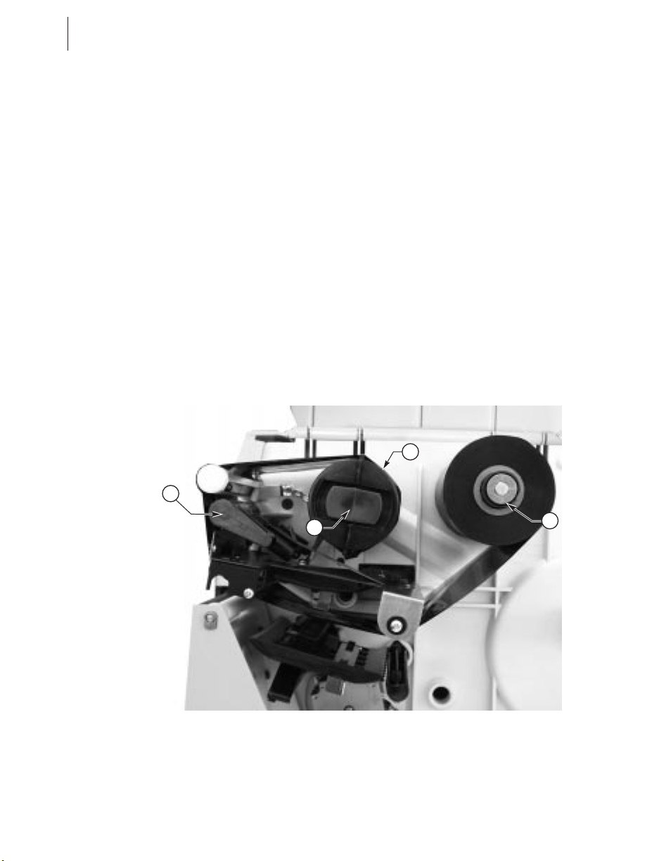
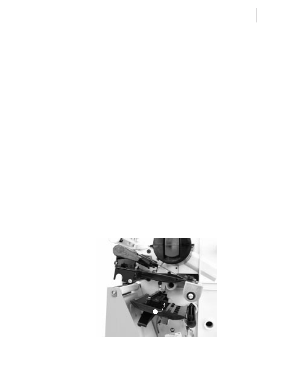
Page 52

44 S400 & S600 User’s Guide
Label
Available
Sensor
Tear-Off/
Peel-Off
Plate
Edge Guide Mark
Figure 25
Figure 26
Rewind
Spindle Full
Sensor
Page 53

S400 & S600 User’s Guide 45
Manual Calibration
Perform a manual calibration whenever you are using pre-printed
media, if the printer is in manual calibration mode, or when the printer
will not auto calibrate.
During this procedure, the media type, label length, media and ribbon
sensor settings, and printing method are determined. Media type is
determined by sensing either continuous or non-continuous media as blank
labels move through the printer. If non-continuous media is sensed, label
length is also calibrated. If ribbon is sensed, the thermal transfer print
method is configured; otherwise, the direct thermal print method is
configured.
The results of this calibration are stored in the printer’s memory and are
retained even if printer power is removed. These parameters remain in
effect until the next calibration is performed.
NOTES: This procedure should only be done once to put the printer into
manual calibration. After that, press the MODE button three times and the
FEED button once when you change media (a label will print that shows the
sensor profile).
If the printer is in the Peel-Off mode, the operator must “catch” the labels as
they are peeled away from the backing during this procedure.
1. Place the head open lever in the open position.
2. Remove the ribbon.
3. Remove approximately 6” of labels from the media roll, enough so that
only the backing material is threaded under the media sensor when the
media is loaded.
4. Reload the media.
5. Press and hold down the PAUSE, FEED, and CANCEL buttons.
6. Turn on the power switch.
7. After the CALIBRATE LED goes out, release the PAUSE, FEED, and
CANCEL buttons.
8. When the PRINTHEAD LED flashes, reload the ribbon.
9. Make sure the media sensor is properly positioned.
10.Close the printhead.
11.A media and ribbon sensor profile will print.
NOTE: To return to Auto Calibration, press and hold the PAUSE,
CANCEL, and MODE buttons when you turn on the printer.
Page 54

46 S400 & S600 User’s Guide
Resetting Printer Parameters
Resetting Factory Defaults
If it is ever necessary to reset all of the factory default values, press and
hold the FEED and PAUSE buttons while turning on the power.
Permanently save these values in memory by pressing the MODE button
four times; the DARKEN, POSITION, and CALIBRATE LEDs will flash,
indicating the changes have been saved. To return to printing mode, turn
off and then turn on the printer.
Resetting Communications Parameters
Pressing and holding the FEED, PAUSE, and MODE buttons while turning
on the power resets only the communications parameters to 9600 baud, 8 bit
word length, no parity, and 1 stop bit. Permanently save these values in
memory by pressing the MODE button four times; the DARKEN,
POSITION, and CALIBRATE LEDs will flash, indicating the changes have
been saved.
Resetting Ribbon Parameters
If it is ever necessary to reset the ribbon parameters to the factory default
values, follow this procedure:
1. Turn off the printer.
2. Open the printhead and remove the ribbon.
3. Turn on the printer while pressing and holding the FEED, CANCEL,
and MODE buttons.
4. After the PRINTHEAD LED flashes, reload the ribbon.
5. Close the printhead.
NOTE: A label automatically prints, showing the ribbon sensor profile.
6. To save, press the MODE button four times.
Page 55

S400 & S600 User’s Guide 47
Printer Diagnostics
Power-On Self Test
A Power-On Self Test (POST) is performed automatically each time the printer
is turned on. This test checks for proper initialization of various electronic
circuits and establishes starting parameters as those stored in the printer’s
memory. During this test sequence, the front panel lights will turn on and off to
insure proper operation.
At the end of this self test, only the POWER LED will remain lit. If other
LEDs are also lit, refer to the troubleshooting table.
Additional Printer Self Tests
These self tests produce sample labels and provide specific information that
help the operator determine the operating conditions for the printer.
Each self test is enabled by holding in a specific front panel button while
turning the power switch on. Keep the button depressed until the
CALIBRATE LED goes out. When the Power-On Self Test is complete,
the selected printer self test will automatically start. To return to printing
mode, turn off and then turn on the printer.
NOTES:
n
When performing self tests, disconnect all communications interface
cables from the printer.
n
When canceling a self test before its actual completion, always turn the
printer power switch off and back on.
n
When performing these self tests while in the Peel-Off mode, the
operator must remove the labels as they become available.
n
When the cutter option is installed and enabled, the labels printed in
these self tests should be automatically cut as they are printed.
Page 56

48 S400 & S600 User’s Guide
CANCEL Key Self Test
This self test prints the printer’s configuration parameters (for example,
printing darkness, label length, and media type) that are currently stored in
configuration (Flash) memory. See Figure 27.
To perform the CANCEL key self test:
1. Press the CANCEL button while turning on the printer.
2. Release the button when the CALIBRATE LED turns off.
3. To return to printing mode, turn off and then turn on the printer.
Figure 27
Page 57

S400 & S600 User’s Guide 49
PAUSE Key Self Test
This self test can be used to provide the test labels required when making
adjustments to the printer’s mechanical assemblies. See Figure 28.
To perform the PAUSE key self test:
1. Press the PAUSE button while turning on the printer.
2. Release the button when the front panel LEDs turn on.
3. To return to printing mode, turn off and then turn on the printer.
NOTE: This self test consists of four individual test features:
n
The initial self test prints 15 labels at 2.4”/second then automatically
pauses the printer. Each time the PAUSE button is pressed, an
additional 15 labels will print, up to 9999 labels.
n
While the printer is paused, pressing the CANCEL button once alters the
self test. Now each time the PAUSE button is pressed, the printer prints
15 labels at maximum speed, up to 9999 labels.
n
While the printer is paused, pressing the CANCEL button a second time
alters the self test again. Now each time the PAUSE button is pressed,
the printer prints 50 labels at 2.4”/second, up to 9999 labels.
n
While the printer is paused, pressing the CANCEL button alters the self
test a third time. Now each time the PAUSE button is pressed, the
printer prints 50 labels at maximum speed, up to 9999 labels.
Figure 28
Page 58

50 S400 & S600 User’s Guide
FEED Key Self Test
The results of this self test will be used to determine the best darkness
setting for a specific media/ribbon combination. Refer to Figure 29.
To perform the FEED key self test:
1. Press the FEED button while turning on the printer.
2. Release the button when the front panel LEDs turn on.
3. To return to printing mode, turn off and then turn on the printer.
NOTES:
n
The FEED key self test
labels will print at
various plus or minus
darkness settings relative
to the current darkness
setting. Inspect these
printouts and determine
which printout has the
best darkness setting.
n
The value on that
printout is added to
(plus) or subtracted from
(minus) the current
darkness value. (For
example, relative
darkness is “5,” so add
that to the number on the
current configuration
label [see the next step]
for the new darkness
setting.)
n
Increments to the actual
darkness value can be
programmed into the
label formats sent to the
printer. To see the actual
value of the current
darkness setting, perform a CANCEL key self test: the value will print
on the configuration printout.
To adjust print darkness, refer to “Print Quality Adjustments” in Routine
Care and Adjustments.
Figure 29
Page 59

S400 & S600 User’s Guide 51
MODE Key Self Test
This self test places the printer in a communications diagnostics mode. In
this mode, the printer prints the ASCII characters and their corresponding
hexadecimal values for any data received from the host computer. See
Figure 30.
To perform the MODE key self test:
1. Press the MODE button while turning on the printer.
2. Release the button when the front panel LEDs turn on.
3. To return to printing mode, turn off and then turn on the printer.
NOTE: Turn off the power to exit this self test.
Figure 30
Page 60

52 S400 & S600 User’s Guide
Page 61

S400 & S600 User’s Guide 53
Specifications
NOTE: Printer specifications are subject to change without notice.
NOTE: Your printer may not have all of the options described in these
specifications.
General Specifications
Height 13" 330 mm
Width 8.25" 210 mm
Depth 17" 432 mm
Weight (option-dependent) 17 lbs 7.71 kg
Auto range 110 VAC +/-20% or
Electrical
Agency approvals
Temperature
Relative
humidity
Communications
Interface
Operating 40 to 105° F 5 to 40° C
Storage -40 to 140° F -40 to 60° C
Operating 20 to 85%, non-condensing
Storage 5 to 85%, non-condensing
230 VAC +/-15%, 47-63 Hz
3 Amps @ 110 VAC, 1.5 Amps @ 230 VAC
UL1950 3rd Edition; CSA22.2 No950-95;
CISPR22-B; EN50082-1:1997; EN60950
Meets FCC Class B and CAN.DOC Class A Rules
DB-9S-type RS-232 serial data interface;
110-57,600 baud; parity, bits/char. and XON-XOFF
or DTR handshake protocols -- all software
selectable
Bi-directional parallel data interface
Page 62

54 S400 & S600 User’s Guide
Printing Specifications
Printing Specifications S400 Printer S600 Printer
Resolution
Dot size (square)
Maximum print width
Print length
Bar code modulus (“X”)
dimension
Programmable constant
printing speeds
DRAM memory
Flash memory (E:)
Ribbon Specifications
Minimum
Maximum
203 dots per inch (8 dots per mm)
0.005" (0.127 mm)
4.09" (104 mm)
0.005" (0.127 mm)
36" (914 mm) 39" (991 mm)
5 mil to 55 mil
2" (51 mm)
2" (51 mm)
3” (76 mm)
4” (102 mm)
1MB 2MB
n/a 1MB
3" (76 mm)
4" (102 mm)
5" (127 mm)
6" (152 mm)
Ribbon width (we
recommend using ribbon
at least as wide as the
media to protect the
printhead from wear).
Standard
lengths
Ribbon core inside diameter 1.0" 25 mm
Maximum ribbon roll diameter 3.2" 81 mm
2:1 media to ribbon roll ratio 984’ 300 m
3:1 media to ribbon roll ratio 1476’ 450 m
Minimum 1.57" 40 mm
Maximum 4.5" 114 mm
Page 63

Media Specifications
S400 & S600 User’s Guide 55
Total
media
width
Label
length
Total
thickness
(includes
liner)
Core size 3.0" 76 mm
Maximum roll diameter 8.0" 203 mm
Inter-label
gap
Ticket/tag notch size (W x L) 0.08" x 0.48" 2 mm x 12 mm
Minimum 0.75" 19 mm
Maximum 4.5" 114 mm
Maximum (cutter installed) 4.0" 102 mm
Minimum
Maximum See “Printing Specifications”
Minimum 0.0023" 0.058 mm
Maximum (printhead
position may need to be
adjusted above 0.01")
Minimum
Maximum 0.16" 4 mm
Media Handling
n
Tear-off mode: Produced in strips
n
Peel-off mode: Dispensed and peeled away from the liner
n
Cutter mode: Printed and individually cut
Tear-Off 0.63" 16 mm
Peel-Off 1.00" 25 mm
Cutter 1.50" 38 mm
0.012" 0.305 mm
0.08"
(0.118" preferred)
2mm
(3 mm preferred)
Page 64

56 S400 & S600 User’s Guide
Options
n
4 MB flash expansion
n
8 MB flash expansion
n
*Peel-Off mode with backing-only rewind feature
n
*Cutter with label catch tray
n
Scalable and bitmap smooth fonts available for text
n
Ethernet
* Factory installed
Contact your authorized Zebra distributor for information.
Zebra Programming Language (ZPL II)
Downloadable graphics
n
(with data compression)
Bit image data transfer and
n
printing, mixed text/graphics
Format inversion
n
Mirror image printing
n
n
Four-position field rotation
(0°, 90°, 180°, 270°)
n
Slew command
Programmable quantity with
n
print pause
Communicates in printable ASCII
n
characters
Controlled via mainframe, mini,
n
PC, Portable Data Terminal
n
Serialized fields
n
In-Spec OCR-A and OCR-B
n
UPC/EAN (nominal 100%
magnification)
Page 65

S400 & S600 User’s Guide 57
Bar Codes
1D 2D
Codabar (supports ratios of
2:1 to 3:1)
Code 11 LOGMARS Code 49
Code 128 (supports
serialization in all subsets
and UCC Case Codes)
Code 39 (supports ratios of
2:1 to 3:1)
Code 93 POSTNET MicroPDF417
EAN 8 Standard 2 of 5 PDF 417
EAN 13 UPC-A QRcode
EAN extensions UPC-E
Industrial 2 of 5 UPC extensions
Interleaved 2 of 5 (supports
ratios of 2:1 to 3:1,
Modulus 10 Check Digit)
MSI Data Matrix
Plessey MaxiCode
Codablock
Standard Printer Fonts
n
Zebra fonts A, B, C, D, E, F, G, H, GS, 0 (S600)
n
Zebra fonts A, B, C, D, E, F, G, H, GS, 0, P, Q, R, S, T, U, V (S400)
n
CG Triumvirate Bold Condensed scalable smooth font
n
IBM Code Page 850 International characters
Optional Printer Fonts
There are many optional character fonts that can be purchased for your
printer in addition to those that are standard in the unit. From time to time,
additions may be made to the list of available fonts. Contact Zebra
Technologies Corporation or an authorized Zebra distributor for further
information.
Fonts can be installed in Flash and additional Flash, up to 8 MB, is
available. Once installed, this font can be used in addition to the standard
fonts available in the printer. Refer to your ZPL II Programming Guide or,
if using another software package to drive your printer, to the instructions
accompanying that package.
Page 66

58 S400 & S600 User’s Guide
Page 67

S400 & S600 User’s Guide 59
Appendix
RS-232 Connector Technical Information
RS-232 Connector Pinouts
Pin. No. Description
1
Not used
2
RXD (receive data) input to the printer
3
TXD (transmit data) output from the printer
DTR (data terminal ready) output from the printer --
4
controls when the host may send data
5
Chassis ground
6
DSR (data set ready) input to the printer
RTS (request to send) output from the printer -- always in
7
the ACTIVE condition when the printer is turned on
8
Not used
9
5 V fused
NOTE: When XON/XOFF handshaking is selected, data flow is controlled
by the ASCII control codes DC1 (XON) and DC3 (XOFF). The DTR
control lead will have no effect.
Interconnecting to DTE Devices
The printer is configured as data terminal equipment (DTE). To connect the
printer to other DTE devices (such as the serial port of a personal
computer), use an RS-232 null modem (crossover) cable. Figure 31 shows
the required cable connections.
Interconnecting to DCE Devices
When the printer is connected via its RS-232 interface to data
communication equipment (DCE) such as a modem, a STANDARD
RS-232 (straight-through) interface cable must be used. Figure 32 shows
the connections required for this cable.
Page 68

60 S400 & S600 User’s Guide
DTE DTE
1
(RD) (RD)
22
(TD)
33
(DTR) (DTR)
44
(SG) (SG)
55
(DSR) (DSR)
66
(RTS) (RTS)
77
(TD)
1
88
99
Figure 31
DCE
1
22
33
44
55
66
77
88
CARRIER DETECT (CD)
RECEIVE DATA (RD)
TRANSMIT DATA (TD)
DATA TERMINAL READY (DTR)
SIGNAL GROUND (SG)
DATA SET READY (DSR)
REQUEST TO SEND (RTS)
CLEAR TO SEND (CTS)
DTE
1
99
Figure 32
Page 69

S400 & S600 User’s Guide 61
Parallel Interface Technical Information
Parallel Connector Pinouts
Pin. No. Description
1
nStrobe/Host Clk
2-9
16-17
19-30
33-34
Data Bits 1-8
10
nACK/PtrClk
11
Busy/Per Busy
12
PError/ACK Data Req.
13
Select/Xflag
14
nauto Fd/Host Busy
15
Not Used
Ground
18
+5V @ 1A Fused
Ground
31
nlnit
32
nFault/nData Avail.
Not Used
35
+5V through 2.2KΩ Resistor
36
NSelectIn/1284 active
Page 70

62 S400 & S600 User’s Guide
Storage and Reshipping
If you are not placing the printer into operation immediately, repackage it
using the original packing materials. The printer may be stored under the
following conditions:
n
Temperature: -40° to 140° F (-40 to 60° C)
n
Relative humidity: 5% to 85% non-condensing
To ship the printer, carefully pack it in a suitable container to avoid damage
during transit. Whenever possible, use the original container from the
factory. A shipping container can be purchased from Zebra Technologies
Corporation, if the original one has been lost or destroyed.
If you use a different container, package the printer carefully to avoid
damage.
CAUTION: When packaging the printer in a rigid container, use shock
mounts or shock-absorbing packing material. A rigid container will allow
shock on the outside to be transmitted undamped to the printer which may
cause damage. Also, before packing, remove all ribbon and media from the
supply and take-up spindles to prevent damage to the printer.
Page 71

S400 & S600 User’s Guide 63
Glossary
alphanumeric Indicating letters, numerals, and characters such as punctuation
marks.
backfeed Backfeed is when the printer pulls the media and ribbon (if used)
backward into the printer so that the beginning of the label to be printed is
properly positioned behind the printhead. Backfeed occurs when you’re
operating the printer in tear-off, peel-off, or cutter mode.
bar code A code by which alphanumeric characters can be represented by a series
of adjacent stripes of different widths. Many different code schemes exist,
such as the universal product code (UPC) or Code 39.
calibration (of a printer) A process in which the printer determines some basic
information needed to print accurately with a particular media/ribbon
combination. To do this, the printer feeds some media and ribbon (if used)
through the printer and senses whether to use the direct thermal or thermal
transfer print method, whether continuous or non-continuous media will be
used, and (if non-continuous media) the length of individual labels/tags.
character set The set of all letters, numerals, punctuation marks, and other
characters that can be expressed by a particular barcode.
check digit A character added to a barcode symbol that indicates to the scanner
that it has read the symbol correctly.
continuous media Label or tagstock that has no web (space between labels),
notch, or gap to separate each label/tag, but rather the media is one long piece
of material.
core diameter The inside diameter of the cardboard core at the center of a roll of
media/ribbon.
cutter A device that can cut each label/tag immediately after it is printed.
diagnostics Information about what printer functions are not working. This
information is used for troubleshooting problems.
direct thermal printing Printing in which direct thermal media is used. No
ribbon is used. Instead, the media is coated with a substance that reacts to
heat to produce an image.
fanfold media Media that comes folded in a rectangular stack, rather than on a
roll.
Page 72

64 S400 & S600 User’s Guide
font A complete set of alphanumeric characters in one style of type. Example:
Times, Helvetica.
ips “inches-per-second” The speed at which the label or tag is printed. Zebra
offers printers that can print from 2 ips to 12 ips.
label An adhesive-backed piece of paper, plastic, or other material on which
information is printed.
label available sensor For printers equipped with the Peel-Off option, this sensor
detects a printed label waiting to be taken or “picked” by the operator. While
it detects this label, the printer will not print additional labels. Once the label
has been taken, printing resumes. Also called “take-label sensor.”
label backing (label liner) The material on which labels are affixed during
manufacture and which is discarded or recycled by the end-users. Label
backing (or liner) has a non-stick surface that allows the label to be easily
removed by the end-user and placed in the desired location.
media Material onto which data is printed by the printer. Types of media include:
tagstock, continuous, fanfold, roll, etc.
media sensor This sensor is located behind the printhead to detect the presence of
media and, for non-continuous media, the position of the web, hole, or notch
that separates each label.
media supply spindle The rotating arm that supports media rolls and provides
consistent media feed to the printhead.
non-volatile memory Electronic memory that retains data even when power is
removed.
print speed The speed at which printing occurs. For thermal transfer printers,
this speed is expressed in terms of ips (inches per second).
printhead wear The degradation of the surface of the printhead and/or the print
elements over time. Heat and abrasion can cause printhead wear. Therefore,
to maximize the life of your printhead use the lowest print darkness setting
(sometimes called “burn temperature” or “head temperature”) and the lowest
printhead/toggle pressure necessary. Also, use ribbon that is as wide or wider
than the media, to protect the printhead from the rougher media.
registration Alignment of printing with respect to the top of a label/tag.
ribbon A band of inked material that is pressed by the printhead against the
media to transfer an image onto the media, which in turn is pressed against the
platen. A ribbon consists of a base film coated with wax or resin “ink.” Zebra
Page 73

S400 & S600 User’s Guide 65
ribbons also have a back coating that protects the printhead from damage.
The ribbon transfers ink onto the media when heated by the printhead.
ribbon wrinkle A wrinkling of the ribbon caused by improper alignment of the
strip plate and/or printhead pressure. This wrinkle can be seen just above the
strip plate. Ribbon wrinkle can cause voids in the print and/or the spent
ribbon to rewind unevenly. This is a condition that should be corrected by
performing adjustment procedures.
roll media Media that comes supplied rolled up on a core (usually cardboard).
Contrast this with fanfold media, which comes folded in a rectangular stack.
Supplies Supplies is a general term for ribbon and media.
Tag A type of media having no adhesive backing but featuring a hole or notch by
which the tag can be hung on something. Usually tags are made of cardboard
or other durable material.
take label sensor See “label available sensor.”
thermal direct printing See “direct thermal printing.”
thermal transfer printing A printing method in which the printhead heats an
ink- or resin-coated ribbon against the media, causing the ink/resin to transfer
onto the media. By selectively heating the ribbon, you can form an image on
the media. See also “ribbon.”
void A space where printing should have occurred but, due to some error
condition, it did not occur. A void can cause a bar code symbol to be read
incorrectly or to not be read at all.
Page 74

66 S400 & S600 User’s Guide
Page 75

S400 & S600 User’s Guide 67
Index
A
AC power cable ...........5
AC power fuse, replacing......30
Adjustments
Backing rewind power roller . . 34
Label top position ........33
Media rest position .......33
Media sensor ..........15
Media sensor position......33
Print darkness ..........31
Print quality ...........31
Print quality check .......31
Ribbon supply spindle .....33
Toggle pressure .........31
ASCII control codes
XON/XOFF ...........59
Autobaud ..............20
Auto calibration...........16
B
Backing rewind power roller,
adjusting ............34
Bar codes ..............57
Burn temperature, adjusting ....31
C
Cabling requirements, serial
and parallel ...........19
Calibration, automatic .......16
Calibration, manual .........45
Cleaning
Cutter module ..........24
Exterior .............23
Interior .............23
Maintenance schedule .....21
Platen roller ...........23
Printhead ............23
Communications parameters,
resetting .............46
Communications parameters,
setting ..............19
Cutter mode .............3
Cutter module, cleaning
Cleaning.............27
Disassembling..........27
Reassembling ..........27
Reinstalling ...........29
Removing ............24
Testing .............29
D
Damage, reporting ..........1
Darkness, adjusting .........31
Defaulting the printer ........19
DCE devices ............59
DTE devices ............59
E
Electrical noise ...........19
Page 76

68 S400 & S600 User’s Guide
F
Factory defaults, resetting .....46
Fanfold media loading ........8
Fonts
Optional .............57
Standard.............57
Front panel buttons
CANCEL button ........16
DOWN button .........16
FEED button ..........16
MODE button ..........17
PAUSE button .........16
UP button ............16
Front panel LEDs
CALIBRATE ..........17
DARKEN ............17
DATA ..............17
PAPER/RIBBON ........17
PAUSE .............17
POSITION ...........17
POWER .............17
PRINTHEAD ..........17
I
Identifying your printer .......2
Interface cables
Crossover (null modem) ....59
Straight-through.........59
L
Label backing material, removal . . 10
Label top position, adjusting ....33
Loading the media ..........7
Loading the ribbon .........12
Lubrication .............30
M
Maintenance manual, ordering....1
Manual calibration .........45
Media
Continuous ...........15
Non-continuous .........15
Media loading ............7
Cutter mode ...........11
Fanfold ..............8
Peel-Off mode ..........9
Roll ................7
Tear-Off mode ..........7
Media rest position, adjusting ...33
Media sensor position, adjusting . . 33
Media sensors............15
N
Null modem cable .........59
O
Operator controls ..........16
Options ...............56
P
Parallel interface ........19,61
Peel-Off mode ............3
Pinouts, parallel connector .....61
Pinouts, serial connector ......59
Power on/off switch ........18
Preventive maintenance kit .....21
Page 77

S400 & S600 User’s Guide 69
Printer diagnostics
CANCEL key self test .....48
FEED key self test .......50
MODE key self test .......51
PAUSE key self test ......49
Power-on self test ........47
Printer identification .........2
Printer status sensors
Backing rewind spindle full...43
Label available .........43
Media ..............43
Printhead ............43
Ribbon .............43
Printer/computer connections
Parallel .............19
Serial ..............18
R
Removing the ribbon ........14
Reporting damage ..........1
Resetting communications
parameters ............46
Resetting factory defaults......46
Resetting ribbon parameters ....46
Reshipping .............62
Ribbon loading ...........12
Ribbon parameters, resetting ....46
Ribbon removal ...........14
Ribbon supply spindle
Low-tension position ......12
Normal position .........12
Ribbon supply spindle, adjusting . . 33
Roll media loading ..........7
S
^SC command ...........20
Sensors ...............15
Serial communications port.....59
Serial interface .........18,59
Site requirements...........2
Software, selecting .........20
Specifications
General .............53
Media ..............55
Media handling .........55
Printing .............54
Ribbon .............54
Storage ...............62
T
Tear-Off mode ............2
Test label, printing .........18
Toggle pressure, adjusting .....31
Troubleshooting table........37
U
Unpacking ..............1
V
Ventilation ..............2
Z
ZPL II Programming Guide,
ordering ..............1
Page 78

70 S400 & S600 User’s Guide
 Loading...